US7662424B2 - Method of making composite particle for electrode, method of making electrode, method of making electrochemical device, apparatus for making composite particle for electrode, apparatus for making electrode, and apparatus for making electrochemical device - Google Patents
Method of making composite particle for electrode, method of making electrode, method of making electrochemical device, apparatus for making composite particle for electrode, apparatus for making electrode, and apparatus for making electrochemical device Download PDFInfo
- Publication number
- US7662424B2 US7662424B2 US10/924,858 US92485804A US7662424B2 US 7662424 B2 US7662424 B2 US 7662424B2 US 92485804 A US92485804 A US 92485804A US 7662424 B2 US7662424 B2 US 7662424B2
- Authority
- US
- United States
- Prior art keywords
- active material
- electrode
- electrode active
- particle
- composite particle
- Prior art date
- Legal status (The legal status is an assumption and is not a legal conclusion. Google has not performed a legal analysis and makes no representation as to the accuracy of the status listed.)
- Expired - Fee Related, expires
Links
- 239000011246 composite particle Substances 0.000 title claims abstract description 260
- 238000004519 manufacturing process Methods 0.000 title claims abstract description 100
- 239000007772 electrode material Substances 0.000 claims abstract description 242
- 239000002245 particle Substances 0.000 claims abstract description 215
- 239000011230 binding agent Substances 0.000 claims abstract description 161
- 239000012752 auxiliary agent Substances 0.000 claims abstract description 151
- 239000012298 atmosphere Substances 0.000 claims abstract description 96
- 238000000034 method Methods 0.000 claims abstract description 82
- 239000011261 inert gas Substances 0.000 claims abstract description 77
- 239000007788 liquid Substances 0.000 claims description 149
- 239000000463 material Substances 0.000 claims description 142
- 239000011149 active material Substances 0.000 claims description 124
- 238000012545 processing Methods 0.000 claims description 101
- 239000003575 carbonaceous material Substances 0.000 claims description 77
- 239000007789 gas Substances 0.000 claims description 71
- 239000011248 coating agent Substances 0.000 claims description 70
- 238000000576 coating method Methods 0.000 claims description 70
- 239000002904 solvent Substances 0.000 claims description 52
- 239000003792 electrolyte Substances 0.000 claims description 37
- 239000000843 powder Substances 0.000 claims description 33
- 239000003990 capacitor Substances 0.000 claims description 23
- 238000005507 spraying Methods 0.000 claims description 21
- 238000001035 drying Methods 0.000 claims description 18
- 238000002844 melting Methods 0.000 claims description 9
- 230000008018 melting Effects 0.000 claims description 9
- 229910044991 metal oxide Inorganic materials 0.000 claims description 9
- 150000004706 metal oxides Chemical class 0.000 claims description 9
- 238000010438 heat treatment Methods 0.000 claims description 8
- 238000001694 spray drying Methods 0.000 claims description 7
- 238000003825 pressing Methods 0.000 claims description 3
- 239000000470 constituent Substances 0.000 abstract description 55
- 239000010410 layer Substances 0.000 description 208
- 210000002381 plasma Anatomy 0.000 description 136
- 239000010408 film Substances 0.000 description 86
- OKTJSMMVPCPJKN-UHFFFAOYSA-N Carbon Chemical compound [C] OKTJSMMVPCPJKN-UHFFFAOYSA-N 0.000 description 44
- 239000008151 electrolyte solution Substances 0.000 description 32
- HBBGRARXTFLTSG-UHFFFAOYSA-N Lithium ion Chemical compound [Li+] HBBGRARXTFLTSG-UHFFFAOYSA-N 0.000 description 31
- 229910001416 lithium ion Inorganic materials 0.000 description 31
- 229910052751 metal Inorganic materials 0.000 description 30
- 239000002184 metal Substances 0.000 description 30
- 229920001940 conductive polymer Polymers 0.000 description 26
- 238000007599 discharging Methods 0.000 description 26
- -1 polyethylene Polymers 0.000 description 26
- XKRFYHLGVUSROY-UHFFFAOYSA-N Argon Chemical compound [Ar] XKRFYHLGVUSROY-UHFFFAOYSA-N 0.000 description 22
- QVGXLLKOCUKJST-UHFFFAOYSA-N atomic oxygen Chemical compound [O] QVGXLLKOCUKJST-UHFFFAOYSA-N 0.000 description 19
- 229910052744 lithium Inorganic materials 0.000 description 19
- 239000001301 oxygen Substances 0.000 description 19
- 229910052760 oxygen Inorganic materials 0.000 description 19
- WHXSMMKQMYFTQS-UHFFFAOYSA-N Lithium Chemical compound [Li] WHXSMMKQMYFTQS-UHFFFAOYSA-N 0.000 description 18
- 239000006185 dispersion Substances 0.000 description 18
- 239000011888 foil Substances 0.000 description 18
- 230000002427 irreversible effect Effects 0.000 description 18
- 239000000203 mixture Substances 0.000 description 17
- 239000007784 solid electrolyte Substances 0.000 description 16
- YCKRFDGAMUMZLT-UHFFFAOYSA-N Fluorine atom Chemical compound [F] YCKRFDGAMUMZLT-UHFFFAOYSA-N 0.000 description 14
- 239000002131 composite material Substances 0.000 description 14
- 229920001971 elastomer Polymers 0.000 description 14
- 230000002349 favourable effect Effects 0.000 description 14
- 239000011737 fluorine Substances 0.000 description 14
- 229910052731 fluorine Inorganic materials 0.000 description 14
- 239000005060 rubber Substances 0.000 description 14
- BQCIDUSAKPWEOX-UHFFFAOYSA-N 1,1-Difluoroethene Chemical compound FC(F)=C BQCIDUSAKPWEOX-UHFFFAOYSA-N 0.000 description 13
- 239000007787 solid Substances 0.000 description 13
- ZMXDDKWLCZADIW-UHFFFAOYSA-N N,N-Dimethylformamide Chemical compound CN(C)C=O ZMXDDKWLCZADIW-UHFFFAOYSA-N 0.000 description 12
- 238000006243 chemical reaction Methods 0.000 description 12
- 229920000642 polymer Polymers 0.000 description 12
- 230000008569 process Effects 0.000 description 12
- 229910052786 argon Inorganic materials 0.000 description 11
- 229910052799 carbon Inorganic materials 0.000 description 11
- 241000894007 species Species 0.000 description 11
- 229920003002 synthetic resin Polymers 0.000 description 11
- 239000000057 synthetic resin Substances 0.000 description 11
- 239000002033 PVDF binder Substances 0.000 description 10
- 229910052782 aluminium Inorganic materials 0.000 description 10
- 239000006183 anode active material Substances 0.000 description 10
- 210000004027 cell Anatomy 0.000 description 10
- 230000007246 mechanism Effects 0.000 description 10
- 239000000178 monomer Substances 0.000 description 10
- 229920002981 polyvinylidene fluoride Polymers 0.000 description 10
- 229920005989 resin Polymers 0.000 description 10
- 239000011347 resin Substances 0.000 description 10
- 239000000126 substance Substances 0.000 description 10
- XAGFODPZIPBFFR-UHFFFAOYSA-N aluminium Chemical compound [Al] XAGFODPZIPBFFR-UHFFFAOYSA-N 0.000 description 9
- 229910002804 graphite Inorganic materials 0.000 description 9
- 239000010439 graphite Substances 0.000 description 9
- 239000011244 liquid electrolyte Substances 0.000 description 9
- 230000002829 reductive effect Effects 0.000 description 9
- XLYOFNOQVPJJNP-UHFFFAOYSA-N water Substances O XLYOFNOQVPJJNP-UHFFFAOYSA-N 0.000 description 9
- 239000006182 cathode active material Substances 0.000 description 8
- 239000006258 conductive agent Substances 0.000 description 8
- 230000000694 effects Effects 0.000 description 8
- 239000005011 phenolic resin Substances 0.000 description 8
- 239000002002 slurry Substances 0.000 description 8
- 239000006230 acetylene black Substances 0.000 description 7
- 230000000052 comparative effect Effects 0.000 description 7
- 150000001875 compounds Chemical class 0.000 description 7
- 229920001577 copolymer Polymers 0.000 description 7
- 125000000524 functional group Chemical group 0.000 description 7
- 239000008187 granular material Substances 0.000 description 7
- 239000007774 positive electrode material Substances 0.000 description 7
- KMTRUDSVKNLOMY-UHFFFAOYSA-N Ethylene carbonate Chemical compound O=C1OCCO1 KMTRUDSVKNLOMY-UHFFFAOYSA-N 0.000 description 6
- SECXISVLQFMRJM-UHFFFAOYSA-N N-Methylpyrrolidone Chemical compound CN1CCCC1=O SECXISVLQFMRJM-UHFFFAOYSA-N 0.000 description 6
- 239000004743 Polypropylene Substances 0.000 description 6
- 239000012159 carrier gas Substances 0.000 description 6
- 239000004020 conductor Substances 0.000 description 6
- NUJOXMJBOLGQSY-UHFFFAOYSA-N manganese dioxide Chemical compound O=[Mn]=O NUJOXMJBOLGQSY-UHFFFAOYSA-N 0.000 description 6
- 239000005518 polymer electrolyte Substances 0.000 description 6
- 229920001155 polypropylene Polymers 0.000 description 6
- 239000002243 precursor Substances 0.000 description 6
- VGGSQFUCUMXWEO-UHFFFAOYSA-N Ethene Chemical compound C=C VGGSQFUCUMXWEO-UHFFFAOYSA-N 0.000 description 5
- 239000005977 Ethylene Substances 0.000 description 5
- 229910001290 LiPF6 Inorganic materials 0.000 description 5
- PXHVJJICTQNCMI-UHFFFAOYSA-N Nickel Chemical compound [Ni] PXHVJJICTQNCMI-UHFFFAOYSA-N 0.000 description 5
- 239000004698 Polyethylene Substances 0.000 description 5
- 238000007796 conventional method Methods 0.000 description 5
- 238000000354 decomposition reaction Methods 0.000 description 5
- 239000002270 dispersing agent Substances 0.000 description 5
- 239000011883 electrode binding agent Substances 0.000 description 5
- 239000011159 matrix material Substances 0.000 description 5
- 229920000573 polyethylene Polymers 0.000 description 5
- 239000000523 sample Substances 0.000 description 5
- 239000000243 solution Substances 0.000 description 5
- BFKJFAAPBSQJPD-UHFFFAOYSA-N tetrafluoroethene Chemical group FC(F)=C(F)F BFKJFAAPBSQJPD-UHFFFAOYSA-N 0.000 description 5
- 235000013162 Cocos nucifera Nutrition 0.000 description 4
- 244000060011 Cocos nucifera Species 0.000 description 4
- RYGMFSIKBFXOCR-UHFFFAOYSA-N Copper Chemical compound [Cu] RYGMFSIKBFXOCR-UHFFFAOYSA-N 0.000 description 4
- XEEYBQQBJWHFJM-UHFFFAOYSA-N Iron Chemical compound [Fe] XEEYBQQBJWHFJM-UHFFFAOYSA-N 0.000 description 4
- 239000004721 Polyphenylene oxide Substances 0.000 description 4
- RTAQQCXQSZGOHL-UHFFFAOYSA-N Titanium Chemical compound [Ti] RTAQQCXQSZGOHL-UHFFFAOYSA-N 0.000 description 4
- 239000000853 adhesive Substances 0.000 description 4
- 230000001070 adhesive effect Effects 0.000 description 4
- 229910021383 artificial graphite Inorganic materials 0.000 description 4
- 125000002915 carbonyl group Chemical group [*:2]C([*:1])=O 0.000 description 4
- 125000003178 carboxy group Chemical group [H]OC(*)=O 0.000 description 4
- 239000000919 ceramic Substances 0.000 description 4
- 230000015271 coagulation Effects 0.000 description 4
- 238000005345 coagulation Methods 0.000 description 4
- 230000007423 decrease Effects 0.000 description 4
- 230000002542 deteriorative effect Effects 0.000 description 4
- 238000003411 electrode reaction Methods 0.000 description 4
- 230000004927 fusion Effects 0.000 description 4
- 239000003349 gelling agent Substances 0.000 description 4
- 150000002500 ions Chemical class 0.000 description 4
- AMXOYNBUYSYVKV-UHFFFAOYSA-M lithium bromide Chemical compound [Li+].[Br-] AMXOYNBUYSYVKV-UHFFFAOYSA-M 0.000 description 4
- KWGKDLIKAYFUFQ-UHFFFAOYSA-M lithium chloride Chemical compound [Li+].[Cl-] KWGKDLIKAYFUFQ-UHFFFAOYSA-M 0.000 description 4
- MHCFAGZWMAWTNR-UHFFFAOYSA-M lithium perchlorate Chemical compound [Li+].[O-]Cl(=O)(=O)=O MHCFAGZWMAWTNR-UHFFFAOYSA-M 0.000 description 4
- 229910001486 lithium perchlorate Inorganic materials 0.000 description 4
- 229910001496 lithium tetrafluoroborate Inorganic materials 0.000 description 4
- 239000002075 main ingredient Substances 0.000 description 4
- 229920000570 polyether Polymers 0.000 description 4
- 239000003505 polymerization initiator Substances 0.000 description 4
- 238000007789 sealing Methods 0.000 description 4
- WEVYAHXRMPXWCK-UHFFFAOYSA-N Acetonitrile Chemical compound CC#N WEVYAHXRMPXWCK-UHFFFAOYSA-N 0.000 description 3
- 229910001560 Li(CF3SO2)2N Inorganic materials 0.000 description 3
- 150000004649 carbonic acid derivatives Chemical class 0.000 description 3
- 230000000536 complexating effect Effects 0.000 description 3
- 238000011161 development Methods 0.000 description 3
- 230000018109 developmental process Effects 0.000 description 3
- 238000002149 energy-dispersive X-ray emission spectroscopy Methods 0.000 description 3
- 230000006870 function Effects 0.000 description 3
- 229910001540 lithium hexafluoroarsenate(V) Inorganic materials 0.000 description 3
- 239000011325 microbead Substances 0.000 description 3
- 239000012046 mixed solvent Substances 0.000 description 3
- 230000004048 modification Effects 0.000 description 3
- 238000012986 modification Methods 0.000 description 3
- 239000007773 negative electrode material Substances 0.000 description 3
- 229910052759 nickel Inorganic materials 0.000 description 3
- 239000003921 oil Substances 0.000 description 3
- 239000003960 organic solvent Substances 0.000 description 3
- 229920002239 polyacrylonitrile Polymers 0.000 description 3
- 230000002441 reversible effect Effects 0.000 description 3
- 239000007921 spray Substances 0.000 description 3
- 238000003860 storage Methods 0.000 description 3
- 229920006132 styrene block copolymer Polymers 0.000 description 3
- YEJRWHAVMIAJKC-UHFFFAOYSA-N 4-Butyrolactone Chemical compound O=C1CCCO1 YEJRWHAVMIAJKC-UHFFFAOYSA-N 0.000 description 2
- IJGRMHOSHXDMSA-UHFFFAOYSA-N Atomic nitrogen Chemical compound N#N IJGRMHOSHXDMSA-UHFFFAOYSA-N 0.000 description 2
- KAKZBPTYRLMSJV-UHFFFAOYSA-N Butadiene Chemical compound C=CC=C KAKZBPTYRLMSJV-UHFFFAOYSA-N 0.000 description 2
- BVKZGUZCCUSVTD-UHFFFAOYSA-L Carbonate Chemical compound [O-]C([O-])=O BVKZGUZCCUSVTD-UHFFFAOYSA-L 0.000 description 2
- XTHFKEDIFFGKHM-UHFFFAOYSA-N Dimethoxyethane Chemical compound COCCOC XTHFKEDIFFGKHM-UHFFFAOYSA-N 0.000 description 2
- UFHFLCQGNIYNRP-UHFFFAOYSA-N Hydrogen Chemical compound [H][H] UFHFLCQGNIYNRP-UHFFFAOYSA-N 0.000 description 2
- 229910000733 Li alloy Inorganic materials 0.000 description 2
- 229910032387 LiCoO2 Inorganic materials 0.000 description 2
- 229910001305 LiMPO4 Inorganic materials 0.000 description 2
- 229910003005 LiNiO2 Inorganic materials 0.000 description 2
- 229910012506 LiSi Inorganic materials 0.000 description 2
- 229920003171 Poly (ethylene oxide) Polymers 0.000 description 2
- 239000005062 Polybutadiene Substances 0.000 description 2
- VYPSYNLAJGMNEJ-UHFFFAOYSA-N Silicium dioxide Chemical compound O=[Si]=O VYPSYNLAJGMNEJ-UHFFFAOYSA-N 0.000 description 2
- PPBRXRYQALVLMV-UHFFFAOYSA-N Styrene Chemical compound C=CC1=CC=CC=C1 PPBRXRYQALVLMV-UHFFFAOYSA-N 0.000 description 2
- WYURNTSHIVDZCO-UHFFFAOYSA-N Tetrahydrofuran Chemical compound C1CCOC1 WYURNTSHIVDZCO-UHFFFAOYSA-N 0.000 description 2
- KLARSDUHONHPRF-UHFFFAOYSA-N [Li].[Mn] Chemical compound [Li].[Mn] KLARSDUHONHPRF-UHFFFAOYSA-N 0.000 description 2
- 238000004220 aggregation Methods 0.000 description 2
- 230000002776 aggregation Effects 0.000 description 2
- 229910052783 alkali metal Inorganic materials 0.000 description 2
- 229910045601 alloy Inorganic materials 0.000 description 2
- 239000000956 alloy Substances 0.000 description 2
- MTAZNLWOLGHBHU-UHFFFAOYSA-N butadiene-styrene rubber Chemical compound C=CC=C.C=CC1=CC=CC=C1 MTAZNLWOLGHBHU-UHFFFAOYSA-N 0.000 description 2
- 229920002678 cellulose Polymers 0.000 description 2
- 235000010980 cellulose Nutrition 0.000 description 2
- 239000003638 chemical reducing agent Substances 0.000 description 2
- UUAGAQFQZIEFAH-UHFFFAOYSA-N chlorotrifluoroethylene Chemical group FC(F)=C(F)Cl UUAGAQFQZIEFAH-UHFFFAOYSA-N 0.000 description 2
- 238000010668 complexation reaction Methods 0.000 description 2
- 229910052802 copper Inorganic materials 0.000 description 2
- 239000010949 copper Substances 0.000 description 2
- 239000011889 copper foil Substances 0.000 description 2
- 229920006037 cross link polymer Polymers 0.000 description 2
- 238000010586 diagram Methods 0.000 description 2
- 229910001873 dinitrogen Inorganic materials 0.000 description 2
- 230000002708 enhancing effect Effects 0.000 description 2
- 125000002573 ethenylidene group Chemical group [*]=C=C([H])[H] 0.000 description 2
- 238000001125 extrusion Methods 0.000 description 2
- 239000012530 fluid Substances 0.000 description 2
- IPBFYZQJXZJBFQ-UHFFFAOYSA-N gamma-octalactone Chemical compound CCCCC1CCC(=O)O1 IPBFYZQJXZJBFQ-UHFFFAOYSA-N 0.000 description 2
- GAEKPEKOJKCEMS-UHFFFAOYSA-N gamma-valerolactone Chemical compound CC1CCC(=O)O1 GAEKPEKOJKCEMS-UHFFFAOYSA-N 0.000 description 2
- 238000005469 granulation Methods 0.000 description 2
- 230000003179 granulation Effects 0.000 description 2
- 238000005087 graphitization Methods 0.000 description 2
- HCDGVLDPFQMKDK-UHFFFAOYSA-N hexafluoropropylene Chemical group FC(F)=C(F)C(F)(F)F HCDGVLDPFQMKDK-UHFFFAOYSA-N 0.000 description 2
- 239000012943 hotmelt Substances 0.000 description 2
- 239000001257 hydrogen Substances 0.000 description 2
- 229910052739 hydrogen Inorganic materials 0.000 description 2
- 230000006872 improvement Effects 0.000 description 2
- 239000004615 ingredient Substances 0.000 description 2
- 239000003999 initiator Substances 0.000 description 2
- 229920000554 ionomer Polymers 0.000 description 2
- 238000003475 lamination Methods 0.000 description 2
- 239000001989 lithium alloy Substances 0.000 description 2
- 229910003002 lithium salt Inorganic materials 0.000 description 2
- 159000000002 lithium salts Chemical class 0.000 description 2
- DMEJJWCBIYKVSB-UHFFFAOYSA-N lithium vanadium Chemical class [Li].[V] DMEJJWCBIYKVSB-UHFFFAOYSA-N 0.000 description 2
- 229910052748 manganese Inorganic materials 0.000 description 2
- 239000011572 manganese Substances 0.000 description 2
- 239000007769 metal material Substances 0.000 description 2
- 150000002739 metals Chemical class 0.000 description 2
- TZIHFWKZFHZASV-UHFFFAOYSA-N methyl formate Chemical compound COC=O TZIHFWKZFHZASV-UHFFFAOYSA-N 0.000 description 2
- 229910003455 mixed metal oxide Inorganic materials 0.000 description 2
- 238000002156 mixing Methods 0.000 description 2
- QJGQUHMNIGDVPM-UHFFFAOYSA-N nitrogen group Chemical group [N] QJGQUHMNIGDVPM-UHFFFAOYSA-N 0.000 description 2
- 229910052756 noble gas Inorganic materials 0.000 description 2
- 150000002835 noble gases Chemical class 0.000 description 2
- 239000010450 olivine Substances 0.000 description 2
- 229910052609 olivine Inorganic materials 0.000 description 2
- 239000003973 paint Substances 0.000 description 2
- 230000035699 permeability Effects 0.000 description 2
- 229920002493 poly(chlorotrifluoroethylene) Polymers 0.000 description 2
- 229920002755 poly(epichlorohydrin) Polymers 0.000 description 2
- 229920002627 poly(phosphazenes) Polymers 0.000 description 2
- 229920002857 polybutadiene Polymers 0.000 description 2
- 239000005023 polychlorotrifluoroethylene (PCTFE) polymer Substances 0.000 description 2
- 229920000139 polyethylene terephthalate Polymers 0.000 description 2
- 239000005020 polyethylene terephthalate Substances 0.000 description 2
- 238000006116 polymerization reaction Methods 0.000 description 2
- 229920001451 polypropylene glycol Polymers 0.000 description 2
- 229920001296 polysiloxane Polymers 0.000 description 2
- 229920001343 polytetrafluoroethylene Polymers 0.000 description 2
- 239000004810 polytetrafluoroethylene Substances 0.000 description 2
- 229920002620 polyvinyl fluoride Polymers 0.000 description 2
- 229920000131 polyvinylidene Polymers 0.000 description 2
- 229920000036 polyvinylpyrrolidone Polymers 0.000 description 2
- 239000001267 polyvinylpyrrolidone Substances 0.000 description 2
- 235000013855 polyvinylpyrrolidone Nutrition 0.000 description 2
- RUOJZAUFBMNUDX-UHFFFAOYSA-N propylene carbonate Chemical compound CC1COC(=O)O1 RUOJZAUFBMNUDX-UHFFFAOYSA-N 0.000 description 2
- 230000001105 regulatory effect Effects 0.000 description 2
- 229910001925 ruthenium oxide Inorganic materials 0.000 description 2
- WOCIAKWEIIZHES-UHFFFAOYSA-N ruthenium(iv) oxide Chemical compound O=[Ru]=O WOCIAKWEIIZHES-UHFFFAOYSA-N 0.000 description 2
- 150000003839 salts Chemical class 0.000 description 2
- 229910052596 spinel Inorganic materials 0.000 description 2
- 239000011029 spinel Substances 0.000 description 2
- 238000003756 stirring Methods 0.000 description 2
- 238000012360 testing method Methods 0.000 description 2
- 238000012719 thermal polymerization Methods 0.000 description 2
- 229920001169 thermoplastic Polymers 0.000 description 2
- 239000004416 thermosoftening plastic Substances 0.000 description 2
- 239000010409 thin film Substances 0.000 description 2
- XOLBLPGZBRYERU-UHFFFAOYSA-N tin dioxide Chemical compound O=[Sn]=O XOLBLPGZBRYERU-UHFFFAOYSA-N 0.000 description 2
- 239000010936 titanium Substances 0.000 description 2
- 229910052719 titanium Inorganic materials 0.000 description 2
- BLTXWCKMNMYXEA-UHFFFAOYSA-N 1,1,2-trifluoro-2-(trifluoromethoxy)ethene Chemical compound FC(F)=C(F)OC(F)(F)F BLTXWCKMNMYXEA-UHFFFAOYSA-N 0.000 description 1
- ZZXUZKXVROWEIF-UHFFFAOYSA-N 1,2-butylene carbonate Chemical compound CCC1COC(=O)O1 ZZXUZKXVROWEIF-UHFFFAOYSA-N 0.000 description 1
- LZDKZFUFMNSQCJ-UHFFFAOYSA-N 1,2-diethoxyethane Chemical compound CCOCCOCC LZDKZFUFMNSQCJ-UHFFFAOYSA-N 0.000 description 1
- WNXJIVFYUVYPPR-UHFFFAOYSA-N 1,3-dioxolane Chemical compound C1COCO1 WNXJIVFYUVYPPR-UHFFFAOYSA-N 0.000 description 1
- GDXHBFHOEYVPED-UHFFFAOYSA-N 1-(2-butoxyethoxy)butane Chemical compound CCCCOCCOCCCC GDXHBFHOEYVPED-UHFFFAOYSA-N 0.000 description 1
- VSKJLJHPAFKHBX-UHFFFAOYSA-N 2-methylbuta-1,3-diene;styrene Chemical compound CC(=C)C=C.C=CC1=CC=CC=C1.C=CC1=CC=CC=C1 VSKJLJHPAFKHBX-UHFFFAOYSA-N 0.000 description 1
- JWUJQDFVADABEY-UHFFFAOYSA-N 2-methyltetrahydrofuran Chemical compound CC1CCCO1 JWUJQDFVADABEY-UHFFFAOYSA-N 0.000 description 1
- GDKSTFXHMBGCPG-UHFFFAOYSA-N 4,4-dimethyl-1,3-dioxane Chemical compound CC1(C)CCOCO1 GDKSTFXHMBGCPG-UHFFFAOYSA-N 0.000 description 1
- 229920000178 Acrylic resin Polymers 0.000 description 1
- 239000004925 Acrylic resin Substances 0.000 description 1
- 229910000838 Al alloy Inorganic materials 0.000 description 1
- BNPJNOLDKSAJSD-UHFFFAOYSA-N C(C)[N+](CC)(CC)CC.[B+3] Chemical compound C(C)[N+](CC)(CC)CC.[B+3] BNPJNOLDKSAJSD-UHFFFAOYSA-N 0.000 description 1
- 229920000049 Carbon (fiber) Polymers 0.000 description 1
- VYZAMTAEIAYCRO-UHFFFAOYSA-N Chromium Chemical compound [Cr] VYZAMTAEIAYCRO-UHFFFAOYSA-N 0.000 description 1
- OIFBSDVPJOWBCH-UHFFFAOYSA-N Diethyl carbonate Chemical compound CCOC(=O)OCC OIFBSDVPJOWBCH-UHFFFAOYSA-N 0.000 description 1
- 229910016855 F9SO2 Inorganic materials 0.000 description 1
- KRHYYFGTRYWZRS-UHFFFAOYSA-M Fluoride anion Chemical compound [F-] KRHYYFGTRYWZRS-UHFFFAOYSA-M 0.000 description 1
- 229910007003 Li(C2F5SO2)2 Inorganic materials 0.000 description 1
- 229910007857 Li-Al Inorganic materials 0.000 description 1
- 229910000552 LiCF3SO3 Inorganic materials 0.000 description 1
- 229910013131 LiN Inorganic materials 0.000 description 1
- 229910013710 LiNixMnyCozO2 Inorganic materials 0.000 description 1
- 229910012381 LiSn Inorganic materials 0.000 description 1
- 229910008447 Li—Al Inorganic materials 0.000 description 1
- 206010024769 Local reaction Diseases 0.000 description 1
- 239000004677 Nylon Substances 0.000 description 1
- 239000004952 Polyamide Substances 0.000 description 1
- 239000004642 Polyimide Substances 0.000 description 1
- 229920000265 Polyparaphenylene Polymers 0.000 description 1
- 230000003213 activating effect Effects 0.000 description 1
- 230000004913 activation Effects 0.000 description 1
- 239000012790 adhesive layer Substances 0.000 description 1
- PNEYBMLMFCGWSK-UHFFFAOYSA-N aluminium oxide Inorganic materials [O-2].[O-2].[O-2].[Al+3].[Al+3] PNEYBMLMFCGWSK-UHFFFAOYSA-N 0.000 description 1
- 238000004458 analytical method Methods 0.000 description 1
- 239000004760 aramid Substances 0.000 description 1
- 229920003235 aromatic polyamide Polymers 0.000 description 1
- 239000011324 bead Substances 0.000 description 1
- 230000008901 benefit Effects 0.000 description 1
- 230000005540 biological transmission Effects 0.000 description 1
- 235000010290 biphenyl Nutrition 0.000 description 1
- 239000004305 biphenyl Substances 0.000 description 1
- 239000012267 brine Substances 0.000 description 1
- 150000001720 carbohydrates Chemical class 0.000 description 1
- 239000006229 carbon black Substances 0.000 description 1
- 235000019241 carbon black Nutrition 0.000 description 1
- 239000004917 carbon fiber Substances 0.000 description 1
- MYWGVEGHKGKUMM-UHFFFAOYSA-N carbonic acid;ethene Chemical compound C=C.C=C.OC(O)=O MYWGVEGHKGKUMM-UHFFFAOYSA-N 0.000 description 1
- 230000003197 catalytic effect Effects 0.000 description 1
- 239000001913 cellulose Substances 0.000 description 1
- 229910052804 chromium Inorganic materials 0.000 description 1
- 239000011651 chromium Substances 0.000 description 1
- 238000004140 cleaning Methods 0.000 description 1
- 239000003245 coal Substances 0.000 description 1
- 229910052681 coesite Inorganic materials 0.000 description 1
- 238000004939 coking Methods 0.000 description 1
- 230000001276 controlling effect Effects 0.000 description 1
- 230000007797 corrosion Effects 0.000 description 1
- 238000005260 corrosion Methods 0.000 description 1
- 229910052906 cristobalite Inorganic materials 0.000 description 1
- 230000006378 damage Effects 0.000 description 1
- 230000003247 decreasing effect Effects 0.000 description 1
- 230000003111 delayed effect Effects 0.000 description 1
- QHGJSLXSVXVKHZ-UHFFFAOYSA-N dilithium;dioxido(dioxo)manganese Chemical compound [Li+].[Li+].[O-][Mn]([O-])(=O)=O QHGJSLXSVXVKHZ-UHFFFAOYSA-N 0.000 description 1
- 125000000118 dimethyl group Chemical group [H]C([H])([H])* 0.000 description 1
- 238000003618 dip coating Methods 0.000 description 1
- 238000004090 dissolution Methods 0.000 description 1
- 238000009826 distribution Methods 0.000 description 1
- 238000009820 dry lamination Methods 0.000 description 1
- 238000003487 electrochemical reaction Methods 0.000 description 1
- 238000005868 electrolysis reaction Methods 0.000 description 1
- 230000005674 electromagnetic induction Effects 0.000 description 1
- 238000009503 electrostatic coating Methods 0.000 description 1
- HQQADJVZYDDRJT-UHFFFAOYSA-N ethene;prop-1-ene Chemical group C=C.CC=C HQQADJVZYDDRJT-UHFFFAOYSA-N 0.000 description 1
- RTZKZFJDLAIYFH-UHFFFAOYSA-N ether Substances CCOCC RTZKZFJDLAIYFH-UHFFFAOYSA-N 0.000 description 1
- 150000002170 ethers Chemical class 0.000 description 1
- JBTWLSYIZRCDFO-UHFFFAOYSA-N ethyl methyl carbonate Chemical compound CCOC(=O)OC JBTWLSYIZRCDFO-UHFFFAOYSA-N 0.000 description 1
- 238000011156 evaluation Methods 0.000 description 1
- 238000011049 filling Methods 0.000 description 1
- 238000010304 firing Methods 0.000 description 1
- HDNHWROHHSBKJG-UHFFFAOYSA-N formaldehyde;furan-2-ylmethanol Chemical compound O=C.OCC1=CC=CO1 HDNHWROHHSBKJG-UHFFFAOYSA-N 0.000 description 1
- 239000000295 fuel oil Substances 0.000 description 1
- 239000007849 furan resin Substances 0.000 description 1
- 229910021397 glassy carbon Inorganic materials 0.000 description 1
- 150000004676 glycans Chemical class 0.000 description 1
- 239000007770 graphite material Substances 0.000 description 1
- 230000005484 gravity Effects 0.000 description 1
- 238000007756 gravure coating Methods 0.000 description 1
- 125000002887 hydroxy group Chemical group [H]O* 0.000 description 1
- 229910010272 inorganic material Inorganic materials 0.000 description 1
- 239000011147 inorganic material Substances 0.000 description 1
- 239000011810 insulating material Substances 0.000 description 1
- 229910052742 iron Inorganic materials 0.000 description 1
- 229920003049 isoprene rubber Polymers 0.000 description 1
- 150000002576 ketones Chemical class 0.000 description 1
- ACFSQHQYDZIPRL-UHFFFAOYSA-N lithium;bis(1,1,2,2,2-pentafluoroethylsulfonyl)azanide Chemical compound [Li+].FC(F)(F)C(F)(F)S(=O)(=O)[N-]S(=O)(=O)C(F)(F)C(F)(F)F ACFSQHQYDZIPRL-UHFFFAOYSA-N 0.000 description 1
- QSZMZKBZAYQGRS-UHFFFAOYSA-N lithium;bis(trifluoromethylsulfonyl)azanide Chemical compound [Li+].FC(F)(F)S(=O)(=O)[N-]S(=O)(=O)C(F)(F)F QSZMZKBZAYQGRS-UHFFFAOYSA-N 0.000 description 1
- 230000014759 maintenance of location Effects 0.000 description 1
- 229910001092 metal group alloy Inorganic materials 0.000 description 1
- 229910021645 metal ion Inorganic materials 0.000 description 1
- VNWKTOKETHGBQD-UHFFFAOYSA-N methane Chemical compound C VNWKTOKETHGBQD-UHFFFAOYSA-N 0.000 description 1
- 238000012821 model calculation Methods 0.000 description 1
- 229910021382 natural graphite Inorganic materials 0.000 description 1
- 239000011255 nonaqueous electrolyte Substances 0.000 description 1
- 239000004745 nonwoven fabric Substances 0.000 description 1
- 229920001778 nylon Polymers 0.000 description 1
- 238000011017 operating method Methods 0.000 description 1
- 239000007800 oxidant agent Substances 0.000 description 1
- 230000001590 oxidative effect Effects 0.000 description 1
- 230000036961 partial effect Effects 0.000 description 1
- 239000003208 petroleum Substances 0.000 description 1
- 239000002006 petroleum coke Substances 0.000 description 1
- ZUOUZKKEUPVFJK-UHFFFAOYSA-N phenylbenzene Natural products C1=CC=CC=C1C1=CC=CC=C1 ZUOUZKKEUPVFJK-UHFFFAOYSA-N 0.000 description 1
- 230000010287 polarization Effects 0.000 description 1
- 229920002587 poly(1,3-butadiene) polymer Polymers 0.000 description 1
- 229920002589 poly(vinylethylene) polymer Polymers 0.000 description 1
- 229920002647 polyamide Polymers 0.000 description 1
- 229920000767 polyaniline Polymers 0.000 description 1
- 229920000728 polyester Polymers 0.000 description 1
- 229920001721 polyimide Polymers 0.000 description 1
- 229920000098 polyolefin Polymers 0.000 description 1
- 229920001282 polysaccharide Polymers 0.000 description 1
- 239000005017 polysaccharide Substances 0.000 description 1
- 239000005033 polyvinylidene chloride Substances 0.000 description 1
- 238000007639 printing Methods 0.000 description 1
- 230000002250 progressing effect Effects 0.000 description 1
- QQONPFPTGQHPMA-UHFFFAOYSA-N propylene Natural products CC=C QQONPFPTGQHPMA-UHFFFAOYSA-N 0.000 description 1
- 125000004805 propylene group Chemical group [H]C([H])([H])C([H])([*:1])C([H])([H])[*:2] 0.000 description 1
- 150000003242 quaternary ammonium salts Chemical class 0.000 description 1
- 230000004044 response Effects 0.000 description 1
- 238000007650 screen-printing Methods 0.000 description 1
- 238000007086 side reaction Methods 0.000 description 1
- 229910052710 silicon Inorganic materials 0.000 description 1
- 239000000377 silicon dioxide Substances 0.000 description 1
- HPALAKNZSZLMCH-UHFFFAOYSA-M sodium;chloride;hydrate Chemical compound O.[Na+].[Cl-] HPALAKNZSZLMCH-UHFFFAOYSA-M 0.000 description 1
- 238000007711 solidification Methods 0.000 description 1
- 230000008023 solidification Effects 0.000 description 1
- 229910001220 stainless steel Inorganic materials 0.000 description 1
- 239000010935 stainless steel Substances 0.000 description 1
- 229910052682 stishovite Inorganic materials 0.000 description 1
- 230000008961 swelling Effects 0.000 description 1
- 238000010345 tape casting Methods 0.000 description 1
- YLQBMQCUIZJEEH-UHFFFAOYSA-N tetrahydrofuran Natural products C=1C=COC=1 YLQBMQCUIZJEEH-UHFFFAOYSA-N 0.000 description 1
- 229920005992 thermoplastic resin Polymers 0.000 description 1
- 229910052718 tin Inorganic materials 0.000 description 1
- 238000006276 transfer reaction Methods 0.000 description 1
- 229910052905 tridymite Inorganic materials 0.000 description 1
- 125000000391 vinyl group Chemical group [H]C([*])=C([H])[H] 0.000 description 1
- 229920002554 vinyl polymer Polymers 0.000 description 1
- 238000009816 wet lamination Methods 0.000 description 1
- 239000002759 woven fabric Substances 0.000 description 1
- 239000004711 α-olefin Substances 0.000 description 1
Images


Classifications
-
- H—ELECTRICITY
- H01—ELECTRIC ELEMENTS
- H01M—PROCESSES OR MEANS, e.g. BATTERIES, FOR THE DIRECT CONVERSION OF CHEMICAL ENERGY INTO ELECTRICAL ENERGY
- H01M4/00—Electrodes
- H01M4/02—Electrodes composed of, or comprising, active material
- H01M4/04—Processes of manufacture in general
-
- H—ELECTRICITY
- H01—ELECTRIC ELEMENTS
- H01M—PROCESSES OR MEANS, e.g. BATTERIES, FOR THE DIRECT CONVERSION OF CHEMICAL ENERGY INTO ELECTRICAL ENERGY
- H01M10/00—Secondary cells; Manufacture thereof
- H01M10/05—Accumulators with non-aqueous electrolyte
- H01M10/052—Li-accumulators
- H01M10/0525—Rocking-chair batteries, i.e. batteries with lithium insertion or intercalation in both electrodes; Lithium-ion batteries
-
- B—PERFORMING OPERATIONS; TRANSPORTING
- B05—SPRAYING OR ATOMISING IN GENERAL; APPLYING FLUENT MATERIALS TO SURFACES, IN GENERAL
- B05B—SPRAYING APPARATUS; ATOMISING APPARATUS; NOZZLES
- B05B13/00—Machines or plants for applying liquids or other fluent materials to surfaces of objects or other work by spraying, not covered by groups B05B1/00 - B05B11/00
- B05B13/02—Means for supporting work; Arrangement or mounting of spray heads; Adaptation or arrangement of means for feeding work
- B05B13/0221—Means for supporting work; Arrangement or mounting of spray heads; Adaptation or arrangement of means for feeding work characterised by the means for moving or conveying the objects or other work, e.g. conveyor belts
- B05B13/025—Means for supporting work; Arrangement or mounting of spray heads; Adaptation or arrangement of means for feeding work characterised by the means for moving or conveying the objects or other work, e.g. conveyor belts the objects or work being present in bulk
-
- H—ELECTRICITY
- H01—ELECTRIC ELEMENTS
- H01G—CAPACITORS; CAPACITORS, RECTIFIERS, DETECTORS, SWITCHING DEVICES, LIGHT-SENSITIVE OR TEMPERATURE-SENSITIVE DEVICES OF THE ELECTROLYTIC TYPE
- H01G11/00—Hybrid capacitors, i.e. capacitors having different positive and negative electrodes; Electric double-layer [EDL] capacitors; Processes for the manufacture thereof or of parts thereof
- H01G11/22—Electrodes
- H01G11/24—Electrodes characterised by structural features of the materials making up or comprised in the electrodes, e.g. form, surface area or porosity; characterised by the structural features of powders or particles used therefor
-
- H—ELECTRICITY
- H01—ELECTRIC ELEMENTS
- H01G—CAPACITORS; CAPACITORS, RECTIFIERS, DETECTORS, SWITCHING DEVICES, LIGHT-SENSITIVE OR TEMPERATURE-SENSITIVE DEVICES OF THE ELECTROLYTIC TYPE
- H01G11/00—Hybrid capacitors, i.e. capacitors having different positive and negative electrodes; Electric double-layer [EDL] capacitors; Processes for the manufacture thereof or of parts thereof
- H01G11/22—Electrodes
- H01G11/26—Electrodes characterised by their structure, e.g. multi-layered, porosity or surface features
- H01G11/28—Electrodes characterised by their structure, e.g. multi-layered, porosity or surface features arranged or disposed on a current collector; Layers or phases between electrodes and current collectors, e.g. adhesives
-
- H—ELECTRICITY
- H01—ELECTRIC ELEMENTS
- H01G—CAPACITORS; CAPACITORS, RECTIFIERS, DETECTORS, SWITCHING DEVICES, LIGHT-SENSITIVE OR TEMPERATURE-SENSITIVE DEVICES OF THE ELECTROLYTIC TYPE
- H01G11/00—Hybrid capacitors, i.e. capacitors having different positive and negative electrodes; Electric double-layer [EDL] capacitors; Processes for the manufacture thereof or of parts thereof
- H01G11/22—Electrodes
- H01G11/30—Electrodes characterised by their material
- H01G11/32—Carbon-based
- H01G11/42—Powders or particles, e.g. composition thereof
-
- H—ELECTRICITY
- H01—ELECTRIC ELEMENTS
- H01G—CAPACITORS; CAPACITORS, RECTIFIERS, DETECTORS, SWITCHING DEVICES, LIGHT-SENSITIVE OR TEMPERATURE-SENSITIVE DEVICES OF THE ELECTROLYTIC TYPE
- H01G11/00—Hybrid capacitors, i.e. capacitors having different positive and negative electrodes; Electric double-layer [EDL] capacitors; Processes for the manufacture thereof or of parts thereof
- H01G11/22—Electrodes
- H01G11/30—Electrodes characterised by their material
- H01G11/46—Metal oxides
-
- H—ELECTRICITY
- H01—ELECTRIC ELEMENTS
- H01G—CAPACITORS; CAPACITORS, RECTIFIERS, DETECTORS, SWITCHING DEVICES, LIGHT-SENSITIVE OR TEMPERATURE-SENSITIVE DEVICES OF THE ELECTROLYTIC TYPE
- H01G11/00—Hybrid capacitors, i.e. capacitors having different positive and negative electrodes; Electric double-layer [EDL] capacitors; Processes for the manufacture thereof or of parts thereof
- H01G11/84—Processes for the manufacture of hybrid or EDL capacitors, or components thereof
- H01G11/86—Processes for the manufacture of hybrid or EDL capacitors, or components thereof specially adapted for electrodes
-
- H—ELECTRICITY
- H01—ELECTRIC ELEMENTS
- H01M—PROCESSES OR MEANS, e.g. BATTERIES, FOR THE DIRECT CONVERSION OF CHEMICAL ENERGY INTO ELECTRICAL ENERGY
- H01M4/00—Electrodes
- H01M4/02—Electrodes composed of, or comprising, active material
- H01M4/04—Processes of manufacture in general
- H01M4/0402—Methods of deposition of the material
- H01M4/0404—Methods of deposition of the material by coating on electrode collectors
-
- H—ELECTRICITY
- H01—ELECTRIC ELEMENTS
- H01M—PROCESSES OR MEANS, e.g. BATTERIES, FOR THE DIRECT CONVERSION OF CHEMICAL ENERGY INTO ELECTRICAL ENERGY
- H01M4/00—Electrodes
- H01M4/02—Electrodes composed of, or comprising, active material
- H01M4/04—Processes of manufacture in general
- H01M4/0402—Methods of deposition of the material
- H01M4/0416—Methods of deposition of the material involving impregnation with a solution, dispersion, paste or dry powder
-
- H—ELECTRICITY
- H01—ELECTRIC ELEMENTS
- H01M—PROCESSES OR MEANS, e.g. BATTERIES, FOR THE DIRECT CONVERSION OF CHEMICAL ENERGY INTO ELECTRICAL ENERGY
- H01M4/00—Electrodes
- H01M4/02—Electrodes composed of, or comprising, active material
- H01M4/13—Electrodes for accumulators with non-aqueous electrolyte, e.g. for lithium-accumulators; Processes of manufacture thereof
- H01M4/139—Processes of manufacture
-
- B—PERFORMING OPERATIONS; TRANSPORTING
- B05—SPRAYING OR ATOMISING IN GENERAL; APPLYING FLUENT MATERIALS TO SURFACES, IN GENERAL
- B05B—SPRAYING APPARATUS; ATOMISING APPARATUS; NOZZLES
- B05B5/00—Electrostatic spraying apparatus; Spraying apparatus with means for charging the spray electrically; Apparatus for spraying liquids or other fluent materials by other electric means
- B05B5/08—Plant for applying liquids or other fluent materials to objects
- B05B5/081—Plant for applying liquids or other fluent materials to objects specially adapted for treating particulate materials
-
- H—ELECTRICITY
- H01—ELECTRIC ELEMENTS
- H01M—PROCESSES OR MEANS, e.g. BATTERIES, FOR THE DIRECT CONVERSION OF CHEMICAL ENERGY INTO ELECTRICAL ENERGY
- H01M4/00—Electrodes
- H01M4/02—Electrodes composed of, or comprising, active material
- H01M4/13—Electrodes for accumulators with non-aqueous electrolyte, e.g. for lithium-accumulators; Processes of manufacture thereof
- H01M4/133—Electrodes based on carbonaceous material, e.g. graphite-intercalation compounds or CFx
-
- H—ELECTRICITY
- H01—ELECTRIC ELEMENTS
- H01M—PROCESSES OR MEANS, e.g. BATTERIES, FOR THE DIRECT CONVERSION OF CHEMICAL ENERGY INTO ELECTRICAL ENERGY
- H01M4/00—Electrodes
- H01M4/02—Electrodes composed of, or comprising, active material
- H01M4/13—Electrodes for accumulators with non-aqueous electrolyte, e.g. for lithium-accumulators; Processes of manufacture thereof
- H01M4/139—Processes of manufacture
- H01M4/1393—Processes of manufacture of electrodes based on carbonaceous material, e.g. graphite-intercalation compounds or CFx
-
- H—ELECTRICITY
- H01—ELECTRIC ELEMENTS
- H01M—PROCESSES OR MEANS, e.g. BATTERIES, FOR THE DIRECT CONVERSION OF CHEMICAL ENERGY INTO ELECTRICAL ENERGY
- H01M4/00—Electrodes
- H01M4/02—Electrodes composed of, or comprising, active material
- H01M4/62—Selection of inactive substances as ingredients for active masses, e.g. binders, fillers
- H01M4/621—Binders
-
- H—ELECTRICITY
- H01—ELECTRIC ELEMENTS
- H01M—PROCESSES OR MEANS, e.g. BATTERIES, FOR THE DIRECT CONVERSION OF CHEMICAL ENERGY INTO ELECTRICAL ENERGY
- H01M4/00—Electrodes
- H01M4/02—Electrodes composed of, or comprising, active material
- H01M4/62—Selection of inactive substances as ingredients for active masses, e.g. binders, fillers
- H01M4/624—Electric conductive fillers
-
- Y—GENERAL TAGGING OF NEW TECHNOLOGICAL DEVELOPMENTS; GENERAL TAGGING OF CROSS-SECTIONAL TECHNOLOGIES SPANNING OVER SEVERAL SECTIONS OF THE IPC; TECHNICAL SUBJECTS COVERED BY FORMER USPC CROSS-REFERENCE ART COLLECTIONS [XRACs] AND DIGESTS
- Y02—TECHNOLOGIES OR APPLICATIONS FOR MITIGATION OR ADAPTATION AGAINST CLIMATE CHANGE
- Y02E—REDUCTION OF GREENHOUSE GAS [GHG] EMISSIONS, RELATED TO ENERGY GENERATION, TRANSMISSION OR DISTRIBUTION
- Y02E60/00—Enabling technologies; Technologies with a potential or indirect contribution to GHG emissions mitigation
- Y02E60/10—Energy storage using batteries
-
- Y—GENERAL TAGGING OF NEW TECHNOLOGICAL DEVELOPMENTS; GENERAL TAGGING OF CROSS-SECTIONAL TECHNOLOGIES SPANNING OVER SEVERAL SECTIONS OF THE IPC; TECHNICAL SUBJECTS COVERED BY FORMER USPC CROSS-REFERENCE ART COLLECTIONS [XRACs] AND DIGESTS
- Y02—TECHNOLOGIES OR APPLICATIONS FOR MITIGATION OR ADAPTATION AGAINST CLIMATE CHANGE
- Y02E—REDUCTION OF GREENHOUSE GAS [GHG] EMISSIONS, RELATED TO ENERGY GENERATION, TRANSMISSION OR DISTRIBUTION
- Y02E60/00—Enabling technologies; Technologies with a potential or indirect contribution to GHG emissions mitigation
- Y02E60/13—Energy storage using capacitors
-
- Y—GENERAL TAGGING OF NEW TECHNOLOGICAL DEVELOPMENTS; GENERAL TAGGING OF CROSS-SECTIONAL TECHNOLOGIES SPANNING OVER SEVERAL SECTIONS OF THE IPC; TECHNICAL SUBJECTS COVERED BY FORMER USPC CROSS-REFERENCE ART COLLECTIONS [XRACs] AND DIGESTS
- Y02—TECHNOLOGIES OR APPLICATIONS FOR MITIGATION OR ADAPTATION AGAINST CLIMATE CHANGE
- Y02T—CLIMATE CHANGE MITIGATION TECHNOLOGIES RELATED TO TRANSPORTATION
- Y02T10/00—Road transport of goods or passengers
- Y02T10/60—Other road transportation technologies with climate change mitigation effect
- Y02T10/70—Energy storage systems for electromobility, e.g. batteries
Definitions
- the present invention relates to a method of making a composite particle for an electrode, which becomes a constituent material of an electrode usable in an electrochemical device such as primary battery, secondary battery (lithium ion secondary battery in particular), electrolytic cell, and capacitor (electrochemical capacitor in particular), a method of making an electrode formed by using thus obtained composite particle for an electrode, and a method of making an electrochemical device equipped with the electrode.
- the present invention also relates to apparatus for making a composite particle for an electrode, an electrode, and an electrochemical device, which are equipped with respective mechanisms based on the methods mentioned above.
- a high-energy battery such as lithium ion secondary battery is mainly constituted by a cathode, an anode, and an electrolytic layer (e.g., a layer made of a liquid or solid electrolyte) disposed between the cathode and anode.
- an electrolytic layer e.g., a layer made of a liquid or solid electrolyte
- the cathode and/or anode has been made by way of the steps of preparing its corresponding electrode forming coating liquid (e.g., in a slurry or paste form) containing an electrode active material therefor, a binder (synthetic resin or the like), a conductive auxiliary agent, and a dispersant and/or solvent; applying the coating liquid to a surface of a collector member (e.g., metal foil); and then drying, so as to form a layer containing the electrode active material (hereinafter referred to as “active material containing layer”) on the surface of the collector member.
- active material containing layer a layer containing the electrode active material
- wet method there are cases where no conductive auxiliary agent is added to the coating liquid. There are also cases where a kneaded product containing the electrode active material, binder, and conductive auxiliary agent without using the dispersant and solvent is prepared in place of the coating liquid and then is formed into a sheet by using a hot roller and/or a hot press (dry method). Further, there are cases where a conductive polymer is added to the coating liquid, so as to form a so-called “polymer electrode”. When the electrolyte layer is solid, there are cases where a method of applying the coating liquid to the surface of the electrolyte layer is employed.
- Electrochemical characteristics of batteries such as charging/discharging potential, reversible capacity, and cycle characteristic heavily depend on the degree of crystallinity (degree of graphitization), surface form, internal structure, surface chemical composition, and the like of the carbon material employed as the anode active material (negative electrode active material).
- degree of crystallinity degree of graphitization
- surface form internal structure
- surface chemical composition and the like of the carbon material employed as the anode active material (negative electrode active material).
- a SEI Solid Electrolyte Interface
- the SEI is generated by a reaction between the anode active material and an electrolytic solution. Once the SEI is formed, the reaction is restrained from advancing further, whereby lithium can be inserted between layers of graphite.
- the SEI is one of causes generating an irreversible capacity.
- the thermal stability concerning the safety of batteries depends on the stability of SEI. Because of a mechanism in which the SEI is formed by the reaction between the anode active material and the electrolytic solution, the SEI is greatly influenced by the amount of oxygen-containing functional groups such as carboxyl group and carbonyl group on the carbon particle surface and the surface structure of the carbon material such as surface crystallinity of carbon particles.
- electrochemical characteristics such as the reversible capacity, voltage resistance characteristic, cycle characteristic, and stability at the time of high-temperature storage are greatly influenced by the degree of crystallinity (degree of graphitization), surface form, internal structure, surface chemical composition, absorbed moisture amount, and the like of particles of the carbon material acting as the electrode active material. It has also been known that the amount of oxygen-containing functional groups such as carboxyl and carbonyl groups on the particle surface of the carbon material greatly affects the electrochemical characteristics mentioned above.
- the above-mentioned technique intends to purify the surface of the carbon material to become the electrode active material by thermal plasma processing, and make the physical and chemical states of the surface attain states suitable for yielding sufficient electrochemical characteristics.
- a lithium secondary battery positive electrode and a method of making the same have been proposed, in which a composite particle constituted by a manganese dioxide (cathode active material) particle and a carbon material powder (conductive auxiliary agent) immobilized on the surface of the manganese dioxide particle is used as an electrode material of the cathode, so as to prevent the charging/discharging capacity of the battery from decreasing because of the cathode, thereby further improving electrochemical characteristics (see, for example, Japanese Patent Application Laid-Open No. HEI 2-262243).
- a method of making a positive electrode mixture for an organic electrolytic solution battery in which a slurry, constituted by a positive electrode active material (cathode active material), a conductive agent (conductive auxiliary agent), a binder, and a solvent, having 20 to 50 wt % of a solid with an average particle size of 10 ⁇ m or smaller is prepared and is granulated by spray drying, so as to further improve characteristics such as discharging characteristic and productivity (see, for example, Japanese Patent Application Laid-Open No. 2000-40504).
- a slurry constituted by a positive electrode active material (cathode active material), a conductive agent (conductive auxiliary agent), a binder, and a solvent, having 20 to 50 wt % of a solid with an average particle size of 10 ⁇ m or smaller is prepared and is granulated by spray drying, so as to further improve characteristics such as discharging characteristic and productivity (see, for example, Japanese Patent Application Laid-Open No. 2000-40504).
- the inventors have found that the occurrence of the above-mentioned problems is greatly influenced by the state of dispersion of the electrode active material, conductive auxiliary agent, and binder failing to construct an effective conduction network, e.g., a nonuniform dispersion state, in the active material containing layer in the electrode obtained in the conventional electrode forming method.
- an effective conduction network e.g., a nonuniform dispersion state
- the inventors have also found that electrochemical characteristics cannot improve as sufficiently as expected if moisture adheres to the surface of the particle made of an electrode active material, or a reaction with oxygen advances on the surface, so that an oxygen-containing functional group (carboxyl group, carbonyl group, or the like) combines with the surface.
- the inventors have found that a granulating step carried out in an inert atmosphere when making a composite particle containing, at least, an electrode active material, a conductive auxiliary agent, and a binder as constituent materials can sufficiently disperse the electrode active material, conductive auxiliary agent, and binder, thereby constructing an effective conductive network, and thus achieved the present invention.
- the present invention provides a method of making a composite particle for an electrode, the method comprising a granulating step of integrating a conductive auxiliary agent and a binder adapted to bind the conductive auxiliary agent and an electrode active material together with a particle made of the electrode active material while in close contact with each other in an inert gas atmosphere so as to form a composite particle for an electrode containing the electrode active material, conductive auxiliary agent, and binder.
- the granulating step is carried out in an inert gas atmosphere, so that the surface of the particle made of the electrode active material is sufficiently prevented from being exposed to an atmosphere such as air containing moisture and oxygen, whereby the surface of the electrode active material is purified, and the surface can keep physical and chemical states suitable for yielding sufficient electrochemical characteristics. Therefore, when the composite particle for an electrode formed by using this electrode active material is employed as a constituent material, an electrode and an electrochemical device which can attain sufficient electrochemical characteristics can be obtained.
- the composite particle obtained by the method of making a composite particle for an electrode in accordance with the present invention is a particle in which the conductive auxiliary agent, electrode active material, and binder are in close contact with each other while in respective quite favorable dispersion states.
- This composite particle is used as a main ingredient of a powder when an active material containing layer of an electrode is made by a dry method which will be explained later, or as a constituent material of a coating liquid or kneaded product when an active material containing layer of an electrode is formed by a wet method which will be explained later.
- a quite favorable electron conduction path (electron conduction network) is constructed three-dimensionally.
- the structure of the electron conduction path can substantially keep its initial state easily even after forming the active material containing layer by heat treatment.
- the structure of the electron conduction path can substantially keep its initial state easily even after preparing the coating liquid or kneaded product containing the composite particle if the preparing condition is adjusted (e.g., a dispersant or solvent for preparing the coating liquid is selected).
- an electrode and electrochemical device which can attain sufficient electrochemical characteristics can be obtained when the composite particle obtained by the method of making a composite particle for an electrode in accordance with the present invention is used as a constituent material.
- the granulating step is carried out in an inert gas atmosphere as such. This can sufficiently prevent the surface of the particle made of an electrode active material from being exposed to an atmosphere such as air containing moisture and oxygen. Therefore, an electrode and electrochemical device which can attain sufficient electrochemical characteristics can be obtained when the composite particle obtained by the method of making a composite particle for an electrode in accordance with the present invention is used as a constituent material from this viewpoint as well.
- inert gas refers to noble gases and nitrogen gas.
- inert gas atmosphere refers to an atmosphere having an inert gas content of at least 99.9%, preferably at least 99.9%, a relative humidity of 0.5% (dew point of about ⁇ 40° C.) or less, preferably 0.04% (dew point of about ⁇ 60° C.) or less, and an oxygen content of 10 ppm or less, preferably 1 ppm or less.
- the “inert gas atmosphere” in the granulating step can be realized by carrying out manufacturing steps subsequent to the granulating step while using “inert gas atmosphere forming means” such as a dry room or glove box.
- electrode active material to become a constituent material of the composite particle refers to the following materials. Namely, “electrode active material” refers to a reducing agent and an oxidizing agent when the electrode to be formed is an electrode used as an anode and a cathode of a primary battery, respectively.
- the “particle made of the electrode active material” may contain materials other than the electrode active material to such an extent that functions of the present invention (functions of the electrode active material) are not lost.
- electrode active material refers to a reducing agent, which can exist chemically stably in any of its reduced and oxidized states while being able to reversibly advance a reducing reaction from the oxidized state to the reduced state and an oxidizing reaction from the reduced state to the oxidized state.
- the “electrode active material” may also be a material adapted to occlude or release (intercalate or dope/undope) a metal ion involving in an electrode reaction.
- the material include carbon materials used in anodes and/or cathodes of lithium ion secondary batteries, and metal oxides (including mixed metal oxides).
- the electrode active material of the anode is referred to as “anode active material”, whereas the electrode active material of the cathode is referred to as “cathode active material”.
- the “anode” in the “anode active material” is one (negative active material) with reference to the polarity of the battery at the time of discharging, whereas the “cathode” in the “cathode active material” is one (positive active material) with reference to the polarity of the battery at the time of discharging.
- Specific examples of the anode and cathode active materials will be explained later.
- electrode active material refers to a metal (including metal alloys), a metal oxide, or a carbon material.
- “integrating a conductive auxiliary agent and a binder with a particle made of the electrode active material while in close contact with each other” refers to bringing respective particles made of the conductive auxiliary agent and binder into close contact with at least a part of the surface of a particle made of the electrode active material. Namely, it will be sufficient if the surface of the particle made of the electrode active material is partly covered with the respective particles made of the conductive auxiliary agent and binder. It is not necessary for the surface to be fully covered.
- the “binder” used in the granulating step in the method of making a composite particle in accordance with the present invention refers to one which can bind the electrode active material and conductive auxiliary agent employed together therewith.
- Adding a conductive polymer having an ionic conductivity as a constituent material when forming the composite particle can also easily construct a quite favorable ion conduction path within the composite particle (i.e., electrode) in the present invention.
- a conductive polymer having an ionic conductivity When usable as a binder to become a constituent material of the composite particle, a conductive polymer having an ionic conductivity can be used.
- the binder having an ionic conductivity also seems to contribute to constructing an ion conduction path within the electrode (composite particle).
- Using such a composite particle can form a polymer electrode constituted by the composite particle.
- a polymer electrolyte having an electronic conductivity may also be used as a binder to become a constituent material of the composite particle.
- Such a configuration allows the present invention to form an electrode having electronic and ionic conductivities superior to those in conventional electrodes easily and reliably.
- a contact interface among the conductive auxiliary agent, electrode active material, and electrolyte (solid electrolyte or liquid electrolyte), which becomes a reaction field of a charge-transfer reaction progressing therewithin, is formed three-dimensionally with a sufficient size.
- the composite particle is formed beforehand with the conductive auxiliary agent, electrode active material, and binder each being dispersed quite favorably, amounts of addition of the conductive auxiliary agent and binder can be made sufficiently smaller than those conventionally used.
- the species of the conductive polymer may be either identical to or different from the above-mentioned conductive polymer to become a constituent material of the composite particle.
- the method of making a composite particle for an electrode in accordance with the present invention further comprises a plasma processing step of subjecting a material made of a carbonaceous material to high-frequency thermal plasma processing in a plasma gas atmosphere so as to yield a particle made of an electrode active material having an electronic conductivity, whereas it will be preferred if the granulating step is a step of integrating the conductive auxiliary agent and the binder with the particle made of the electrode active material obtained after the plasma processing step in close contact with each other in the inert gas atmosphere so as to form the composite particle for an electrode containing the electrode active material, conductive auxiliary agent, and binder.
- the plasma processing step When the plasma processing step is provided, and the granulating step using the particle made of the electrode active material obtained by the plasma processing step is carried out in the inert gas atmosphere as such, the surface of the electrode active material is purified, and the surface can keep physical and chemical states suitable for yielding sufficient electrochemical characteristics.
- the inventors have found that the carbon material with the purified surface is exposed to an atmosphere such as air containing moisture and oxygen after the thermal plasma processing in the conventional techniques using the thermal plasma processing. Therefore, moisture may adhere again to the purified surface of the carbon material after the plasma processing, and a reaction with oxygen may proceed on the surface, so that oxygen-containing functional groups (carboxyl group, carbonyl group, etc.) may combine with the surface, whereby electrochemical characteristics may not be obtained by the plasma processing as fully as expected.
- an atmosphere such as air containing moisture and oxygen after the thermal plasma processing in the conventional techniques using the thermal plasma processing. Therefore, moisture may adhere again to the purified surface of the carbon material after the plasma processing, and a reaction with oxygen may proceed on the surface, so that oxygen-containing functional groups (carboxyl group, carbonyl group, etc.) may combine with the surface, whereby electrochemical characteristics may not be obtained by the plasma processing as fully as expected.
- thermodesorption mass spectrometer TDS
- the inventors measured those left for 2 hours in the air (at a temperature of 25° C. with a relative humidity of 45%) among carbon materials subjected to high-frequency thermal plasma processing, and verified that a large amount of a gas derived from hydroxyl groups occurred from carbon material surfaces.
- the plasma processing step When the plasma processing step is provided, and the granulating step using the particle made of the electrode active material obtained by the plasma processing step is carried out in the inert gas atmosphere in the present invention, by contrast, the surface of the electrode active material is purified, and the surface can keep physical and chemical states suitable for yielding sufficient electrochemical characteristics.
- the carbon material for an electrode in accordance with the present invention is subjected to the high-frequency thermal plasma processing, a turbostratic structure is formed near the material surface, and the minute amounts of oxygen and hydrogen on the material surface are eliminated, whereby the surface is modified. Since the plasma processing is carried out in the plasma gas atmosphere in particular, the SEI generating reaction is made favorable, and the SEI can improve its stability. Also, the irreversible capacity occurring when the SEI is generated can sufficiently be reduced.
- an electrode and electrochemical device which can yield sufficient electrochemical characteristics can be obtained when a composite particle for an electrode formed by using the carbon material is employed as a constituent material.
- the reversible capacity and charging/discharging efficiency (initial charging/discharging efficiency) of the electrode and electrochemical device can be improved.
- high-frequency thermal plasma is a plasma generated from a middle pressure (about 10 to 70 kPa) to 1 atm. Since plasmas approximating a thermal equilibrium can be obtained unlike normal low-pressure plasmas, not only a local reaction is effected by plasmas and the like, but also substances existing in the system can attain a high temperature. Therefore, the high-frequency thermal plasma enables both the generation of a high-temperature phase and the surface modification. Examples of specific phenomena seem to include surface nitrogenization when N 2 is used for the plasma gas, surface hydrogenization when H 2 is used for the plasma gas, physical destruction at an atomic level, and particle surface cleaning.
- a material (a particle made of a carbonaceous material) of the particle made of a carbonaceous material is graphitized by ultrahigh-temperature processing using a high-frequency thermal plasma atmosphere, and the resulting surface is bombarded with ions, radicals, etc., so as to be modified.
- carbonaceous material refers to one which becomes a carbon material having an electronic conductivity when subjected to the high-frequency thermal plasma processing. It is not always necessary for the carbonaceous material to have an electronic conductivity by itself.
- the carbonaceous material in this case includes not only carbon materials, but also resin materials containing carbon as a constituent element. Examples of the carbonaceous material include graphite, pitch type materials, coconut shells, and phenol resin.
- the granulating step is carried out according to spray drying. This can yield an electrode having a uniform density and the like while lowering the irreversible capacity.
- the granulating step in accordance with the present invention comprises a material liquid preparing step of preparing a material liquid containing the binder, the conductive auxiliary agent, and a solvent; a fluidizing step of putting a particle made of the electrode active material into a fluidizing tank and causing the particle made of the electrode active material to form a fluidized layer; and a spraying/drying step of spraying the material liquid into the fluidized layer containing the particle made of the electrode active material so that the material liquid is attached to the particle made of the electrode active material and is dried, so as to remove the solvent from the material liquid attached to a surface of the particle made of the electrode active material, and cause the binder to bring the particle made of the electrode active material and a particle made of the conductive auxiliary agent into close contact with each other.
- This composite particle is used as a main ingredient of a powder when an active material containing layer of an electrode is made by a dry method which will be explained later, or as a constituent material of a coating liquid or kneaded product when an active material containing layer of an electrode is formed by a wet method which will be explained later.
- a quite favorable electron conduction path (electron conduction network) is constructed three-dimensionally.
- the structure of the electron conduction path can substantially keep its initial state even after forming the active material containing layer by heat treatment.
- the structure of the electron conduction path can substantially keep its initial state easily even after preparing the coating liquid or kneaded product containing the composite particle if the preparing condition is adjusted (e.g., a dispersant or solvent for preparing the coating liquid is selected).
- an electrode and electrochemical device which can attain sufficient electrochemical characteristics can be obtained when the resulting composite particle is used as a constituent material even if the binder is used as a constituent material.
- the inventors have found that, since the conventional electrode forming methods employ the above-mentioned method using a coating liquid (slurry) or kneaded product containing at least the electrode active material, conductive auxiliary agent, and binder when forming an electrode, the occurrence of the above-mentioned problems is greatly influenced by the state of dispersion of the electrode active material, conductive auxiliary agent, and binder failing to construct an effective conduction network, e.g., a nonuniform dispersion state, in the active material containing layer in the resulting electrode.
- an effective conduction network e.g., a nonuniform dispersion state
- the inventors have found that, in the process of drying the coating film, the conductive auxiliary agent and binder having a low specific gravity float up to the vicinity of the coating film surface, whereby the state of dispersion of the electrode active material, conductive auxiliary agent, and binder becomes a state failing to construct an effective conduction network, e.g., a nonuniform dispersion state, thus making the electrode active material, conductive auxiliary agent, and binder fail to attain a sufficient adhesion therebetween, by which no favorable electron conduction path can be constructed in the resulting active material containing layer.
- an effective conduction network e.g., a nonuniform dispersion state
- the composite particle disclosed in Japanese Patent Application Laid-Open No. HEI 2-262243 has a low mechanical strength, so that the carbon material powder immobilized on the surface of a manganese dioxide particle in the process of forming an electrode is easy to peel off. This easiness of peeling is one of reasons why the dispersibility of the carbon material powder in the resulting electrode is likely to become insufficient, whereby electrode characteristics cannot be improved as reliably and sufficiently as expected.
- the positive electrode mix for an organic electrolytic solution battery disclosed in Japanese Patent Application Laid-Open No. 2000-40504 is made as a mass (composite particle) constituted by a positive electrode active material, a conductive agent, and a binder by spray drying a slurry comprising a solvent into hot air.
- a mass (composite particle) constituted by a positive electrode active material, a conductive agent, and a binder by spray drying a slurry comprising a solvent into hot air.
- the inventors have found that drying and solidification proceed while the positive electrode active material, conductive agent, and binder are dispersed in the solvent, whereby the conductive agent and binder do not come into close contact with the surface of the particle made of the positive electrode active material constituting the resulting mass (composite particle) while keeping their respective effective conduction networks and being sufficiently dispersed.
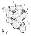
- particles made of the positive electrode active material constituting a resulting mass (composite particle) P 100 in the technique disclosed in Japanese Patent Application Laid-Open No. 2000-40504 include a large amount of particles P 11 surrounded by only aggregates P 33 constituted by the large binder and are electrically isolated without being used in the mass (composite particle) P 100 .
- the inventors have also found that, when particles made of the conductive agent form aggregates during drying, particles made of the conductive agent are unevenly distributed as aggregates P 22 , so that no sufficient electron conduction path (electron conduction network) can be constructed in the mass (composite particle) P 100 , whereby no sufficient electronic conductivity can be obtained.
- aggregates P 22 of particles made of the conductive agent may be surrounded with only the aggregates P 33 made of the large binder, so as to be electrically isolated, whereby no sufficient electron conduction path (electron conduction network) can be constructed in the mass (composite particle) P 100 , and no sufficient electronic conductivity can be obtained from this viewpoint as well.
- electron conduction network electron conduction network
- the same slurry contains a positive electrode active material (cathode active material), a conductive agent (conductive auxiliary agent), and a binder, whereby the state of dispersion of the electrode active material, conductive auxiliary agent, and binder in the resulting granule (composite particle) depends on the state of dispersion of the electrode active material, conductive auxiliary agent, and binder in the slurry (the state of dispersion of the electrode active material, conductive auxiliary agent, and binder in the process of drying droplets of the slurry in particular).
- the aggregations and uneven distributions of the binder and conductive auxiliary agent mentioned above with reference to FIG. 25 occur, so that the dispersion state of the electrode active material, conductive auxiliary agent, and binder in the resulting granule (composite particle) becomes a state failing to construct an effective conduction network, e.g., a nonuniform dispersion state, whereby no sufficient adhesion is attained between the electrode active material, conductive auxiliary agent, and binder, and no favorable electronic conduction path is constructed in thus obtained active material containing layer.
- an effective conduction network e.g., a nonuniform dispersion state
- the inventors have further found that, in the conventional techniques such as those for the composite particles of Japanese Patent Application Laid Open Nos. HEI 2-262243 and 2000-40504, the state of dispersion of the electrode active material, conductive auxiliary agent, and binder in the coating liquid becomes uneven, whereby the adhesion of the electrode active material and conductive auxiliary agent to the collector is not sufficiently obtained.
- the problem of the state of the dispersion of the electrode active material, conductive auxiliary agent, and binder in the coating liquid and the electrode obtained therefrom becoming uneven and these ingredients being distributed unevenly in the electrode becomes remarkable when the electrode is made thicker.
- Electrodes such as the composite particles disclosed in Japanese Patent Application Laid-Open Nos. HEI 2-262243 and 2000-40504 use an insulating or poorly electronically conductive binder together with the electrode active material and conductive auxiliary agent from the viewpoint of securing the stability in forms of electrodes, and thus fail to ensure the electronic conductivity of electrodes sufficiently.
- the inventors have further found that the problems mentioned above occur in the case of making electrodes by using the composite particles disclosed in Japanese Patent Application Laid-Open Nos. HEI 2-262243 and 2000-40504, since the binder is also employed therein.
- capacitors e.g., electrochemical capacitors such as electric double layer capacitors
- electrolytic cells having an electrode made by a method using a coating liquid or kneaded product containing at least a conductive auxiliary agent, a binder, and an electronically conductive material (carbon material or metal oxide) in place of the electrode active material in the batteries.
- the present invention can yield unexpected results by employing the above-mentioned preferred granulating step and performing the granulating step in an inert gas atmosphere.
- the electrode when the composite particle containing electrode active material, conductive auxiliary agent, and binder is formed beforehand by way of the above-mentioned preferred granulating step and is used as an electrode, the electrode (composite particle) having a specific resistance value (or an internal resistance value normalized with an apparent volume) sufficiently lower than that of the electrode active material itself can be constructed, though it contains the binder.
- Employing the above-mentioned preferred granulating step can more reliably form the above-mentioned composite particle in which a quite favorable electron conduction path (electron conduction network) is constructed three-dimensionally.
- the electrode formed by using the composite particle for an electrode obtained by way of the above-mentioned preferred granulating step is formed while in a state keeping the structure of the above-mentioned composite particle, whereby the state where “the electrode active material and the conductive auxiliary agent are electrically connected to each other without being isolated” is realized in the active material containing layer. Therefore, a quite favorable electron conduction path (electron conduction network) is three-dimensionally constructed in the active material containing layer.
- the electrode active material and the conductive auxiliary agent are electrically connected to each other without being isolated in the composite particle” indicates that a particle made of the electrode active material (or its aggregate) and a particle made of the conductive auxiliary agent (or its aggregate) are electrically connected to each other without “substantially” being isolated in the active material containing layer. More specifically, it indicates that the particle made of the electrode active material (or its aggregate) and the particle made of the conductive auxiliary agent (or its aggregate) are electrically connected to each other not without completely being isolated, but to such an extent that an electric resistance at a level where effects of the present invention can be achieved.
- the state where “the electrode active material and the conductive auxiliary agent are electrically connected to each other without being isolated in the composite particle” can be verified by SEM (Scanning Electron Microscope) and TEM (Transmission Electron Microscope) photographs and analysis data of EDX (Energy Dispersive X-ray Fluorescence Spectrometer) of cross sections of the composite particle of the electrode in accordance with the present invention.
- SEM Sccanning Electron Microscope
- TEM Transmission Electron Microscope
- the aggregation of constituent particles constituting the composite particle can fully be prevented from advancing, whereby constituent particles in the resulting particle can sufficiently be kept from being distributed unevenly.
- the conductive auxiliary agent and binder can be brought into contact with the electrolytic solution, so as to be dispersed selectively and favorably over the surface of the electrode active material which can be involved in electrode reactions.
- the composite particle becomes a particle in which the conductive auxiliary agent, electrode active material, and binder are in close contact with each other while in respective quite favorable dispersion states.
- the particle size and form of the composite particle in accordance with the present invention can arbitrarily be controlled by regulating the temperature in the fluidizing tank, the amount of the material liquid sprayed in the fluidizing tank, the amount of the electrode active material put into a fluid flow (e.g., gas flow) generated in the fluidizing tank, the speed of the fluidized layer, the mode (laminar flow, turbulent flow, etc.) of the flow (circulation) of the fluidized layer (fluid flow), etc.
- a fluid flow e.g., gas flow
- the fluidizing method is not restricted in particular.
- a fluidizing tank generating a gas flow, by which particles are fluidized a fluidizing tank which fluidizes particles in a rotary fashion with a stirring blade, and a fluidizing tank which fluidizes particles by vibration can be used.
- the fluidizing step generates a gas flow in the fluidizing tank, and puts a particle made of the electrode active material into the gas flow, so as to fluidize the particle made of the electrode active material.
- the inventors presume that a quite favorable electron conduction path (electron conduction network) is three-dimensionally constructed within thus obtained composite particle, whereby an electron conduction path (electron conduction network) much better than that in conventional electrodes is three-dimensionally constructed within the electrode (composite particle) employed in the electrochemical device in accordance with the present invention.
- the granulating step adjust the temperature in the fluidizing tank to a temperature of at least 50° C. but not greatly exceeding the melting point of the binder, more preferably at least 50° C. but not higher than the melting point of the binder.
- the melting point of the binder is about 200° C., for example.
- the problem mentioned above can sufficiently be prevented from occurring, though depending on conditions.
- the temperature in the fluidizing tank is not higher than the melting point of the binder, the above-mentioned problem does not occur.
- the gas flow generated in the fluidizing tank in the granulating step be a gas flow comprising an inert gas.
- the humidity (relative humidity) in the fluidizing tank is a dew point of ⁇ 40° C. or lower within the preferred temperature range mentioned above.
- inert gas refers to a gas belonging to noble gases and nitrogen gas.
- the solvent contained in the material liquid be a solvent adapted to dissolve or disperse the binder and disperse the conductive auxiliary agent. This can also enhance the dispersibility of the binder, conductive auxiliary agent, and electrode active material in the resulting composite particle. From the viewpoint of further enhancing the dispersibility of the binder, conductive auxiliary agent, and electrode active material in the composite particle, it will be preferred if the solvent contained in the material liquid is adapted to dissolve the binder and disperse the conductive auxiliary agent.
- the solvent contained in the material liquid have a moisture content of 100 ppm or less.
- the moisture content in the solvent exceeds 100 ppm, the moisture adsorbed by the composite particle increases so much that the loss caused by side reactions in electrochemical reactions tends to increase.
- the present invention may further comprise a particle storing step of encapsulating the composite particle for an electrode obtained after the granulating step into a case capable of storing the composite particle in a closed state in the inert gas atmosphere. This can more reliably keep the purified surface of the electrode active material (carbon material or metal oxide) contained in the manufactured composite particle for an electrode.
- the present invention provides a method of making an electrode comprising, at least, a conductive active material containing layer containing an electrode active material and a conductive collector disposed in a state electrically in contact with the active material containing layer, the method comprising a composite particle forming step including a granulating step of integrating a conductive auxiliary agent and a binder adapted to bind the conductive auxiliary agent and the electrode active material together with a particle made of the electrode active material while in close contact with each other in an inert gas atmosphere so as to form a composite particle for an electrode containing the electrode active material, conductive auxiliary agent, and binder; and an active material containing layer forming step of forming an active material containing layer at a part to be formed with the active material containing layer in the collector in the inert gas atmosphere by using the composite particle.
- the active material containing layer is formed by the particle for an electrode obtained by the above-mentioned method of making a composite particle for an electrode as such, an electrode having excellent electrode characteristics can be obtained.
- the composite particle forming step in the method of making an electrode in accordance with the present invention further comprises a plasma processing step of subjecting a material made of a carbonaceous material to high-frequency thermal plasma processing in a plasma gas atmosphere so as to yield a particle made of an electrode active material having an electronic conductivity, whereas it will be preferred if the granulating step is a step of integrating the conductive auxiliary agent and the binder with the particle made of the electrode active material obtained after the plasma processing step in close contact with each other in the inert gas atmosphere so as to form the composite particle for an electrode containing the electrode active material, conductive auxiliary agent, and binder.
- the plasma processing step When the plasma processing step is provided, and the granulating step using the particle made of the electrode active material obtained by the plasma processing step is carried out in the inert gas atmosphere as such, an electrode having sufficient electrode characteristics and electrochemical characteristics can be obtained effectively. In particular, the irreversible capacity of the resulting electrode can sufficiently be reduced.
- the composite particle forming step may include steps other than the granulating step, it will be preferred if all the manufacturing steps after the plasma processing step are carried out in the inert gas atmosphere.
- the granulating step in the method of making an electrode in accordance with the present invention comprises a material liquid preparing step of preparing a material liquid containing the binder, the conductive auxiliary agent, and a solvent; a fluidizing step of putting a particle made of the electrode active material into a fluidizing tank and causing the particle made of the electrode active material to form a fluidized layer; and a spraying/drying step of spraying the material liquid into the fluidized layer containing the particle made of the electrode active material so that the material liquid is attached to the particle made of the electrode active material and is dried, so as to remove the solvent from the material liquid attached to a surface of the particle made of the electrode active material, and cause the binder to bring the particle made of the electrode active material and a particle made of the conductive auxiliary agent into close contact with each other.
- the active material containing layer forming step in the method of making an electrode in accordance with the present invention may comprise a sheet forming step of subjecting a powder containing at least the composite particle to heating and pressing so as to yield a sheet containing at least the composite particle; and an active material containing layer arranging step of arranging the sheet as the active material containing layer on the collector. Even when employing a dry method as such while using the binder in the above-mentioned constituent material, an electrode which can attain excellent electrode characteristics and an electrode having such excellent electrode characteristics that the irreversible capacity can sufficiently be lowered can be obtained more reliably.
- “powder containing at least the composite particle” may be constituted by the composite particle alone.
- the “powder containing at least the composite particle” may further contain the binder and/or the conductive auxiliary agent.
- the content of the composite particle in the powder is at least 80 mass % on the basis of the total mass of the powder.
- the sheet forming step is carried out by using a hot roll press.
- the hot roll press has a pair of hot rolls, between which the “powder containing at least the composite particle” is fed, heated, and pressed, so as to form a sheet.
- the sheet to become the active material containing layer can be formed easily and reliably.
- the active material containing layer may be formed by the dry method using the composite particle in the active material containing layer forming step in the method of making an electrode in accordance with the present invention as in the foregoing, effects of the present invention mentioned above can also be obtained when the active material containing layer is formed by the wet method as follows.
- the active material containing layer forming step in the method of making an electrode in accordance with the present invention may comprise a coating liquid preparing step of preparing an electrode forming coating liquid by adding the composite particle to a liquid adapted to disperse or knead the composite particle; a step of applying the electrode forming coating liquid to the part to be formed with the active material containing layer in the collector; and a step of solidifying a liquid film constituted by the electrode forming coating liquid applied to the part to be formed with the active material containing layer in the collector.
- liquid adapted to disperse the composite particle is preferably a liquid which does not dissolve the binder in the composite particle, but may have a characteristic of partly dissolving the binder near the surface of the composite particle as long as the electric contact between composite particles can sufficiently be secured and effects of the present invention can be achieved.
- the binder and conductive auxiliary agent may further be added to the composite particle as other ingredients of the composite particle.
- the binder added here is one which is soluble in the “liquid adapted to disperse the composite particle”.
- the active material containing layer forming step may comprise a kneaded product preparing step of preparing a kneaded product preparing step of preparing an electrode forming kneaded product containing the composite particle by adding the composite particle to the liquid; a step of applying the electrode forming kneaded product to the part to be formed with the active material containing layer in the collector; and a step of solidifying a coating film constituted by the electrode forming kneaded product applied to the part to be formed with the active material containing layer in the collector.
- the method of making an electrode in accordance with the present invention further comprises an electrode storing step of encapsulating the electrode obtained after the active material containing layer forming step into a case capable of storing the composite particle in a closed state in the inert gas atmosphere.
- an electrode storing step of encapsulating the electrode obtained after the active material containing layer forming step into a case capable of storing the composite particle in a closed state in the inert gas atmosphere This can more reliably keep the purified surface of the electrode active material (carbon material or metal oxide) contained in the composite particle for an electrode contained in the manufactured electrode.
- the present invention provides a method of making an electrochemical device comprising, at least, an anode, a cathode, and an electrolyte layer having an ionic conductivity, the anode and cathode opposing each other by way of the electrolyte layer, the method comprising an electrode forming step of forming an electrode by way of a composite particle forming step including a granulating step of integrating a conductive auxiliary agent and a binder adapted to bind the conductive auxiliary agent and an electrode active material together with a particle made of the electrode active material while in close contact with each other in an inert gas atmosphere so as to form a composite particle for an electrode containing the electrode active material, conductive auxiliary agent, and binder; and an active material containing layer forming step of forming an active material containing layer at a part to be formed with the active material containing layer in the collector in the inert gas atmosphere by using the composite particle; wherein the electrode obtained by the electrode forming step is used as at least
- an electrochemical device having excellent charging/discharging characteristics which can sufficiently lower the irreversible capacity can be obtained easily and reliably.
- electrochemical device refers to one comprising, at least, a first electrode (anode) and a second electrode (cathode) which oppose each other, and an electrolyte layer having an ionic conductivity disposed between the first and second electrodes.
- the “electrolyte layer having an ionic conductivity” is any of (1) a porous separator formed from an insulating material, which is immersed with an electrolytic solution (or a gel-like electrolyte obtained by adding a gelling agent to an electrolytic solution); (2) a solid electrolyte film (a film made of a solid polymer electrolyte or a film containing an ionically conductive inorganic material); (3) a layer made of a gel-like electrolyte obtained by adding a gelling agent to an electrolytic solution; and (4) a layer made of an electrolytic solution.
- the first and second electrodes may contain therewithin their respective electrolytes to be used.
- a laminate constituted by the first electrode (anode), electrolyte layer, and second electrode (cathode) in each of the configurations of (1) to (3) is referred to as “matrix” when necessary.
- the matrix includes not only those having a three-layer structure as those of the configurations of (1) to (3), but also those with five or more layers constituted by alternately laminated electrodes and electrolyte layers.
- the electrochemical device may have a configuration of a module in which a plurality of unit cells are arranged in series or parallel within a case.
- the electrolyte layer may comprise a solid electrolyte.
- the solid electrolyte comprises a ceramic solid electrolyte, a solid polymer electrolyte, or a gel-like electrolyte obtained by adding a gelling agent to a liquid electrolyte.
- an electrochemical device in which all the constituents are solid e.g., so-called “all-solid battery”
- all-solid battery e.g., so-called “all-solid battery”. This can easily reduce the weight of the electrochemical device and improve energy density and safety.
- the electrolyte layer may comprise a separator made of an insulating porous body, and a liquid electrolyte or solid electrolyte infiltrated in the separator.
- a solid electrolyte a ceramic solid electrolyte, a solid polymer electrolyte, or a gel-like electrolyte obtained by adding a gelling agent to a liquid electrolyte can be used in this case as well.
- the composite particle forming step in the method of making an electrochemical device in accordance with the present invention further comprises a plasma processing step of subjecting a material made of a carbonaceous material to high-frequency thermal plasma processing so as to yield a particle made of an electrode active material having an electronic conductivity in a plasma gas atmosphere, whereas it will be preferred if the granulating step is a step of integrating the conductive auxiliary agent and the binder with the particle made of the electrode active material obtained after the plasma processing step in close contact with each other in the inert gas atmosphere so as to form the composite particle for an electrode containing the electrode active material, conductive auxiliary agent, and binder.
- the plasma processing step When the plasma processing step is provided, and the granulating step using the particle made of the electrode active material obtained by the plasma processing step is carried out in the inert gas atmosphere as such, an electrode having sufficient electrode characteristics and electrochemical characteristics can be obtained effectively. In particular, the irreversible capacity of the resulting electrode can sufficiently be reduced.
- the composite particle forming step may include steps other than the granulating step, it will be preferred if all the manufacturing steps after the plasma processing step are carried out in the inert gas atmosphere.
- the granulating step in the method of making an electrochemical device in accordance with the present invention comprises a material liquid preparing step of preparing a material liquid containing the binder, the conductive auxiliary agent, and a solvent; a fluidizing step of putting a particle made of the electrode active material into a fluidizing tank and causing the particle made of the electrode active material to form a fluidized layer; and a spraying/drying step of spraying the material liquid into the fluidized layer containing the particle made of the electrode active material so that the material liquid is attached to the particle made of the electrode active material and is dried, so as to remove the solvent from the material liquid attached to a surface of the particle made of the electrode active material, and cause the binder to bring the particle made of the electrode active material and a particle made of the conductive auxiliary agent into close contact with each other.
- the present invention provides an apparatus for making a composite particle for an electrode, the apparatus comprising a granulating part for carrying out a granulating process of integrating a conductive auxiliary agent and a binder adapted to bind the conductive auxiliary agent and an electrode active material together with a particle made of the electrode active material while in close contact with each other in an inert gas atmosphere so as to form a composite particle for an electrode containing the electrode active material, conductive auxiliary agent, and binder; and an inert gas atmosphere forming device for carrying out the granulating process in the inert gas atmosphere.
- the apparatus for making a composite particle for an electrode in accordance with the present invention comprises the granulating part and the inert gas atmosphere forming device operating according to the method of making a composite particle for an electrode in accordance with the present invention, the method of making a composite particle for an electrode can be carried out effectively. Therefore, even when a binder is used as a constituent material, a composite particle for an electrode which can easily and reliably form an electrode which can attain excellent electrode characteristics, and a composite particle for an electrode which can sufficiently lower the irreversible capacity can be obtained easily and reliably.
- the apparatus for making a composite particle for an electrode in accordance with the present invention further comprises a plasma processing part for carrying out a plasma processing process of subjecting a material made of a carbonaceous material to high-frequency thermal plasma processing in a plasma gas atmosphere so as to yield a particle made of an electrode active material having an electronic conductivity, whereas it will be preferred if the granulating part is a granulating part for carrying out a granulating process of integrating the conductive auxiliary agent and the binder with the particle made of the electrode active material obtained after the plasma processing step in close contact with each other in the inert gas atmosphere so as to form the composite particle for an electrode containing the electrode active material, conductive auxiliary agent, and binder.
- the particle made of the electrode active material obtained in the plasma processing part is fed to the granulating part, and the granulating step in accordance with the present invention is carried out in the inert gas atmosphere as such, a composite particle for an electrode which can easily and reliably form an electrode which can attain excellent electrode characteristics, and a composite particle for an electrode which can sufficiently lower the irreversible capacity can be obtained easily and reliably even if a binder is used as a constituent material.
- the apparatus for making a composite particle for an electrode in accordance with the present invention further comprises a particle storing part for carrying out a particle storing step of encapsulating the composite particle for an electrode obtained after the granulating step into a case capable of storing the composite particle in a closed state in the inert gas atmosphere.
- a particle storing part for carrying out a particle storing step of encapsulating the composite particle for an electrode obtained after the granulating step into a case capable of storing the composite particle in a closed state in the inert gas atmosphere. This can more reliably keep the purified surface of the electrode active material (carbon material or metal oxide) contained in the manufactured composite particle for an electrode.
- the present invention provides an apparatus for making an electrode comprising, at least, a conductive active material containing layer containing an electrode active material and a conductive collector disposed in a state electrically in contact with the active material containing layer, the apparatus comprising a granulating part for carrying out a granulating step of integrating a conductive auxiliary agent and a binder adapted to bind the conductive auxiliary agent and the electrode active material together with a particle made of the electrode active material while in close contact with each other in an inert gas atmosphere so as to form a composite particle for an electrode containing the electrode active material, conductive auxiliary agent, and binder; an active material containing layer forming part for forming the active material containing layer at a part to be formed with the active material containing layer in the collector by using the composite particle; and an inert gas atmosphere forming device for carrying out the processes in the granulating part and active material containing layer forming part in the inert gas atmosphere.
- the apparatus for making an electrode in accordance with the present invention comprises the granulating part, active material containing layer forming part, and inert gas atmosphere forming device operating according to the above-mentioned method of making a composite particle for an electrode and method of making an electrode in accordance with the present invention, the method of making an electrode in accordance with the present invention can be carried out effectively, whereby an electrode having excellent electrode characteristics can be obtained easily and reliably even when a binder is used as a constituent material.
- the apparatus for making an electrode in accordance with the present invention further comprises a plasma processing part for carrying out a plasma processing step of subjecting a material made of a carbonaceous material to high-frequency thermal plasma processing in a plasma gas atmosphere so as to yield a particle made of an electrode active material having an electronic conductivity, whereas it will be preferred if the granulating part is a granulating part for carrying out a granulating step of integrating the conductive auxiliary agent and the binder with the particle made of the electrode active material obtained after the plasma processing step in close contact with each other so as to form the composite particle for an electrode containing the electrode active material, conductive auxiliary agent, and binder.
- the particle made of the electrode active material obtained in the plasma processing part is fed to the granulating part, and the granulating step in accordance with the present invention is carried out in the inert gas atmosphere as such, an electrode having excellent electrode characteristics can be obtained easily and reliably even if a binder is used as a constituent material.
- the apparatus for making an electrode in accordance with the present invention further comprises an electrode storing part for carrying out a step of encapsulating the electrode obtained after the active material containing layer is formed in the active material containing layer forming part into a case capable of storing the electrode in a closed state in an inert gas atmosphere.
- an electrode storing part for carrying out a step of encapsulating the electrode obtained after the active material containing layer is formed in the active material containing layer forming part into a case capable of storing the electrode in a closed state in an inert gas atmosphere.
- This can more reliably keep the purified surface of the electrode active material (carbon material or metal oxide) contained in the composite particle for an electrode contained in the manufactured electrode.
- the present invention provides an apparatus for making an electrochemical device comprising, at least, an anode, a cathode, and an electrolyte layer having an ionic conductivity, the anode and cathode opposing each other by way of the electrolyte layer; the anode and cathode comprising, at least, a conductive active material containing layer containing an electrode active material, and a conductive collector disposed in electric contact with the active material containing layer; the apparatus comprising a granulating part for carrying out a granulating step of integrating a conductive auxiliary agent and a binder adapted to bind the conductive auxiliary agent and the electrode active material together with a particle made of the electrode active material while in close contact with each other in an inert gas atmosphere so as to form a composite particle for an electrode containing the electrode active material, conductive auxiliary agent, and binder; an active material containing layer forming part for forming the active material containing layer at a part to be formed with the
- the apparatus for making an electrochemical device in accordance with the present invention comprises the granulating part, active material containing layer forming part, device assembling part, and inert gas atmosphere forming device operating according to the above-mentioned method of making a composite particle for an electrode, method of making an electrode in accordance with the present invention, and method of making an electrochemical device, the method of making an electrochemical device in accordance with the present invention can be carried out effectively, whereby an electrochemical device having excellent charging/discharging characteristics can be obtained easily and reliably even when a binder is used as a constituent material of the electrode.
- the apparatus for making an electrochemical device in accordance with the present invention further comprises a plasma processing part for carrying out a plasma processing step of subjecting a material made of a carbonaceous material to high-frequency thermal plasma processing in a plasma gas atmosphere so as to yield a particle made of an electrode active material having an electronic conductivity, whereas it will be preferred if the granulating part is a granulating part for carrying out a granulating step of integrating the conductive auxiliary agent and the binder with the particle made of the electrode active material obtained after the plasma processing step in close contact with each other in the inert gas atmosphere so as to form the composite particle for an electrode containing the electrode active material, conductive auxiliary agent, and binder.
- the particle made of the electrode active material obtained in the plasma processing part is fed to the granulating part, and the granulating step in accordance with the present invention is carried out in the inert gas atmosphere as such, an electrochemical device having excellent charging/discharging characteristics can be obtained easily and reliably even if a binder is used as a constituent material.
- the composite particle for an electrode and electrode obtained by the present invention can be utilized in an electrochemical device, whereas the electrochemical device obtained by the present invention can be used as a backup power supply for a power supply for a portable device (small-sized electronic device) and as an auxiliary power supply for a hybrid car.
- FIG. 1 is a front view showing the basic configuration of an example of the electrochemical device (lithium ion secondary battery) made by a preferred embodiment of the manufacturing method in accordance with the present invention
- FIG. 2 is a developed view of the inside of the electrochemical device shown in FIG. 1 as seen in a direction normal to a surface of an anode 10 ;
- FIG. 3 is a schematic sectional view showing the electrochemical device shown in FIG. 1 taken along the line X 1 -X 1 thereof;
- FIG. 4 is a schematic sectional view showing a main part of the electrochemical device shown in FIG. 1 taken along the line X 2 -X 2 thereof;
- FIG. 5 is a schematic sectional view showing a main part of the electrochemical device shown in FIG. 1 taken along the line Y-Y thereof;
- FIG. 6 is a schematic sectional view showing an example of the basic configuration of a film to become a constituent material for a case of the electrochemical device shown in FIG. 1 ;
- FIG. 7 is a schematic sectional view showing another example of the basic configuration of a film to become a constituent material for a case of the electrochemical device shown in FIG. 1 ;
- FIG. 8 is a schematic sectional view showing an example of the basic configuration of the anode in the electrochemical device shown in FIG. 1 ;
- FIG. 9 is a schematic sectional view showing an example of the basic configuration of the cathode in the electrochemical device shown in FIG. 1 ;
- FIG. 10 is a schematic sectional view showing an example of the basic configuration of a composite particle made in a granulating step in the manufacturing method of the present invention.
- FIG. 11 is an explanatory view showing a basic configuration of a preferred embodiment of the apparatus for making an electrochemical device in accordance with the present invention.
- FIG. 12 is a schematic diagram of a high-frequency thermal plasma generator (plasma torch) employed for carrying out plasma processing;
- FIG. 13 is an explanatory view showing an example of the granulating step when making an electrode
- FIG. 14 is an explanatory view showing an example of the coating liquid preparing step when making an electrode by a wet method
- FIG. 15 is an explanatory view for explaining a step of forming an electrode sheet using an electrode forming coating liquid
- FIG. 16 is an explanatory view for explaining a step of forming the electrode sheet using the electrode forming coating liquid
- FIG. 17 is an explanatory view for explaining steps of forming an electrode from the electrode sheet
- FIG. 18 is an explanatory view showing an example of the sheet forming step when making an electrode by a dry method
- FIG. 19 is a schematic sectional view roughly showing the internal structure of an active material containing layer of an electrode made by the present invention.
- FIG. 20 is an explanatory view showing an example of the procedure of filling the case with a nonaqueous electrolytic solution
- FIG. 21 is a perspective view showing an electrochemical capacitor when seal parts of the case are bent.
- FIG. 22 is a schematic sectional view showing the basic configuration of another embodiment of the electrochemical device obtained by the method of making an electrochemical device in accordance with the present invention.
- FIG. 23 is a schematic perspective view showing the basic configuration of still another embodiment of the electrochemical device obtained by the method of making an electrochemical device in accordance with the present invention.
- FIG. 24 is an explanatory view showing a manufacturing method when forming an electrochemical device made of a laminate constituted by a plurality of electrodes and separators.
- FIG. 25 is a schematic sectional view roughly showing a partial configuration of a conventional composite particle for an electrode, and the internal structure of an active material containing layer of an electrode formed by using the conventional composite particle for an electrode.
- FIG. 1 is a front view showing the basic configuration of an example of the electrochemical device (lithium ion secondary battery) made by a preferred embodiment of the manufacturing method in accordance with the present invention.
- FIG. 2 is a developed view of the inside of the electrochemical device shown in FIG. 1 as seen in a direction normal to a surface of an anode 10 .
- FIG. 3 is a schematic sectional view showing the electrochemical device shown in FIG. 1 taken along the line X 1 -X 1 thereof.
- FIG. 4 is a schematic sectional view showing a main part of the electrochemical device shown in FIG. 1 taken along the line X 2 -X 2 thereof.
- FIG. 5 is a schematic sectional view showing a main part of the electrochemical device shown in FIG. 1 taken along the line Y-Y thereof.
- a lithium ion secondary battery 1 is mainly constituted by a planar anode 10 and a planar cathode 20 which oppose each other, a planar electrolyte layer 40 (separator or the like) disposed between the anode 10 and cathode 20 in close contact therewith, a nonaqueous electrolytic solution, a case 50 accommodating them in a closed state, an anode lead 12 having one end part electrically connected to the anode 10 and the other end part projecting out of the case 50 , and a cathode lead 22 having one end part electrically connected to the cathode 20 and the other end part projecting out of the case 50 .
- the “anode” 10 and “cathode” 20 are determined with reference to polarities of the lithium ion secondary battery 1 at the time of discharging. Therefore, at the time of charging, the “anode 10 ” and “cathode 20 ” become “cathode” and “anode”, respectively.
- the lithium ion secondary battery 1 has configurations explained in the following. Constituents in this embodiment will now be explained in detail with reference to FIGS. 1 to 9 .
- the case 50 is formed by using a pair of films (a first film 51 and a second film 52 ) opposing each other.
- the first film 51 and second film 52 in this embodiment are connected to each other.
- the case 50 in this embodiment is formed by folding a rectangular film made of a single composite package film at a fold line X 3 -X 3 shown in FIG. 2 , and bonding a pair of overlying opposed edge parts (an edge part 51 B of the first film 51 and an edge part 52 B of the second film 52 in the drawing) to each other with an adhesive or by heat sealing.
- the first film 51 and second film 52 represent parts having respective surfaces opposing each other formed when a single rectangular film 53 is folded as mentioned above.
- edge parts of the first film 51 and second film 52 after being bonded together will be referred to as “seal parts”.
- the anode lead 12 and cathode lead 22 are arranged such that each has one end projecting out of the seal part where the edge part 51 B of the first film 51 and the edge part 52 B of the second film 52 are bonded together.
- the film constituting the first film 51 and second film 52 is a flexible film as mentioned above.
- the film is light in weight and easy to form thinner, whereby the lithium ion secondary battery itself can be formed like a thin film. This can easily improve the original volume energy density, and the volume energy density with reference to the volume of the space where the lithium ion secondary battery is to be placed.
- the film is not restricted in particular as long as it is a flexible film. From the viewpoint of effectively preventing moisture from entering the inside of the case 50 from the outside and electrolyte components from escaping from the inside of the case 50 to the outside while securing sufficient mechanical strength and lightweight characteristic of the case, however, it will be preferred if the film is a “composite package film” comprising, at least, an innermost layer made of a synthetic resin in contact with the nonaqueous electrolytic solution and a metal disposed on the upper side of the innermost layer.
- Examples of the composite package film usable as the first film 51 and second film 52 include those having respective configurations shown in FIGS. 6 and 7 .
- the composite package film 53 shown in FIG. 6 comprises an innermost layer 50 a , made of a synthetic resin, having an inner face F 53 in contact with the nonaqueous electrolyte solution; and a metal layer 50 c disposed on the other face (outer face) of the innermost layer 50 a .
- the composite package film 54 shown in FIG. 7 has a configuration in which an outermost layer 50 b made of a synthetic resin is further disposed on the outer face of the metal layer 50 c of the composite package film 53 shown in FIG. 6 .
- the composite package film usable as the first film 51 and second film 52 is not restricted in particular as long as it is a composite package material comprising at least two layers including at least one synthetic resin layer such as the above-mentioned innermost layer and a metal layer such as a metal foil. From the viewpoint of more reliably yielding the effects mentioned above, however, it will be more preferable if the film is constituted by at least three layers comprising the innermost layer 50 a , the outermost layer 50 b made of a synthetic resin disposed on the outer face side of the case 50 located farthest from the innermost layer 50 a , and at least one metal layer 50 c disposed between the innermost layer 50 a and outermost layer 50 b as with the composite package film 54 shown in FIG. 7 .
- the innermost layer 50 a is a flexible layer, and the constituent material thereof is not restricted in particular as long as it is a synthetic resin which can exhibit the flexibility while having a chemical stability (characteristic of generating neither chemical reactions, dissolution, nor swelling) with respect to a nonaqueous electrolytic solution 30 employed, and a chemical stability with respect to oxygen and water (moisture in the air).
- a material further having a low permeability to oxygen, water (moisture in the air), and components of the nonaqueous electrolytic solution 30 is preferred.
- the material include thermoplastic resins such as polyethylene, polypropylene, acid-denatured polyethylene, acid-denatured polypropylene, polyethylene ionomer, and polypropylene ionomer.
- this synthetic resin layer may use the same constituent material as with the innermost layer 50 a.
- the metal layer 50 c is a layer formed from a metal material having an anti corrosion characteristic with respect to oxygen, water (moisture in the air), and the nonaqueous electrolytic solution.
- a metal material having an anti corrosion characteristic with respect to oxygen, water (moisture in the air), and the nonaqueous electrolytic solution for example, metal foils made of aluminum, aluminum alloys, titanium, chromium, etc. may be used.
- FIG. 8 is a schematic sectional view showing an example of the basic configuration of the anode in the lithium ion secondary battery shown in FIG. 1 .
- FIG. 9 is a schematic sectional view showing an example of the basic configuration of the cathode in the lithium ion secondary battery shown in FIG. 1 .
- the anode 10 is constituted by a collector 16 , and an anode active material containing layer 18 formed on the collector 16 .
- the cathode 20 is constituted by a collector 26 , and a cathode active material containing layer 28 formed on the collector 26 .
- the collectors 16 and 26 are not restricted in particular as long as they are conductors which can sufficiently move electric charges to the anode active material containing layer 18 and cathode active material containing layer 28 , whereby collectors employed in known lithium ion secondary batteries can be used.
- Examples of the collectors 16 and 26 include metal foils made of aluminum, copper, etc.
- the active material containing layer 18 of the anode 10 is mainly constituted by the composite particle P 10 shown in FIG. 10 .
- FIG. 10 is a schematic sectional view showing an example of the basic configuration of a composite particle made in a granulating step in the manufacturing method of the present invention.
- the composite particle P 10 is constituted by particles P 1 made of an electrode active material, particles P 2 made of a conductive auxiliary agent, and particles P 3 made of a binder.
- the average particle size of the composite particles P 10 is not restricted in particular.
- the composite particle P 10 has a structure in which the particles P 1 made of the electrode active material and the particles P 2 made of the conductive auxiliary agent are electrically connected to each other without being isolated. Therefore, a structure in which the particles P 1 made of the electrode active material and the particles P 2 made of the conductive auxiliary agent are electrically connected to each other without being isolated is also formed in the active material containing layer 18 .
- the electrode active material constituting the composite particle P 10 contained in the anode 10 is not restricted in particular, whereby known electrode active materials can be used.
- the electrode active material include carbon materials such as graphite, carbon hard to become graphite, carbon easy to become graphite, and low-temperature-firing carbon which can occlude/release (intercalate or dope/undope) lithium ions; metals such as Al, Si, and Sn combinable with lithium; amorphous compounds mainly composed of oxides such as SiO 2 and SnO 2 ; lithium titanate (Li 3 Ti 5 O 12 ); etc.
- the conductive auxiliary agent constituting the composite particle P 10 contained in the anode 10 is not restricted in particular, whereby known conductive auxiliary agents can be used.
- the conductive auxiliary agent include carbon materials such as carbon blacks, synthetic graphite having a high crystallinity, and natural graphite; fine powders of metals such as copper, nickel, stainless steel, and iron; mixtures of the above-mentioned carbon materials and metal fine powders; and conductive oxides such as ITO.
- the binder constituting the composite particle P 10 contained in the anode 10 is not restricted in particular as long as it can bind particles of the electrode active material to the particles P 2 made of the conductive auxiliary agent.
- the binder include fluorine resins such as polyvinylidene fluoride (PVDF), polytetrafluoroethylene (PTFE), tetrafluoroethylene/hexafluoropropylene copolymer (FEP), tetrafluoroethylene/perfluoroalkylvinyl ether copolymer (PFA), ethylene/tetrafluoroethylene copolymer (ETFE), polychlorotrifluoroethylene (PCTFE), ethylene/chlorotrifluoroethylene copolymer (ECTFE), and polyvinyl fluoride (PVF).
- PVDF polyvinylidene fluoride
- PTFE polytetrafluoroethylene
- FEP tetrafluoroethylene/hexafluoropropylene
- binder other than those mentioned above examples include vinylidene fluoride type fluorine rubbers such as vinylidene fluoride/hexafluoropropylene type fluoride rubber (VDF/HFP type fluorine rubber), vinylidene fluoride/hexafluoropropylene/tetrafluoroethylene type fluorine rubber (VDF/HPF/TFE type fluorine rubber), vinylidene fluoride/pentafluoropropylene type fluorine rubber (VDF/PFP type fluorine rubber), vinylidene fluoride/pentafluoropropylene/tetrafluoroethylene type fluorine rubber (VDF/PFP/TFE type fluorine rubber), vinylidene fluoride/perfluoromethylvinyl ether/tetrafluoroethylene type fluorine rubber (VDF/PFMVE/TFE type fluorine rubber), and vinylidene fluoride/chlorotrifluoroethylene type fluorine rubber (VDF
- binder examples include polyethylene, polypropylene, polyethylene terephthalate, aromatic polyamide, cellulose, styrene/butadiene rubber, isoprene rubber, butadiene rubber, and ethylene/propylene rubber.
- thermoplastic elastomeric polymers such as styrene/butadiene/styrene block copolymer, its hydrogenated product, styrene/ethylene/butadiene/styrene block copolymer, styrene/isoprene/styrene block copolymer, and its hydrogenated product may be used.
- syndiotactic 1,2-polybutadiene, ethylene/vinyl acetate copolymer, propylene/ ⁇ -olefin (having a carbon number of 2 to 12) copolymer, etc. may be used.
- conductive polymers may be used.
- Particles made of a conductive polymer may further be added to the composite particle P 10 as its constituent. Further, when forming an electrode by a dry method using the composite particle P 10 , the particles may be added as a constituent of a powder containing at least the composite particle. When forming an electrode by a wet method using the composite particle P 10 , particles made of the conductive polymer may be added as a constituent material of a coating liquid or kneaded product containing the composite particle P 10 at the time of preparing the coating liquid or kneaded product.
- the conductive polymer is not restricted in particular as long as it has a lithium ion conductivity, for example.
- the conductive polymer include those in which monomers of polymer compounds (polyether type polymer compounds such as polyethylene oxide and polypropylene oxide, cross-linked polymers of polyether compounds, polyepichlorohydrin, polyphosphazene, polysiloxane, polyvinylpyrrolidone, polyvinylidene carbonate, polyacrylonitrile, etc.) are complexed with lithium salts such as LiClO 4 , LiBF 4 , LiPF 6 , LiAsF 6 , LiCl, LiBr, Li(CF 3 SO 2 ) 2 N, and LiN(C 2 F 5 SO 2 ) 2 or alkali metal salts mainly composed of lithium.
- a polymerization initiator used for complexation include photopolymerization initiators and thermal polymerization initiators suitable for the above-mentioned monomers.
- the secondary battery 1 When the secondary battery 1 is a metal lithium secondary battery, its anode (not depicted) may be an electrode, made of metal lithium or a lithium alloy alone, also acting as a collector.
- the lithium alloy is not restricted in particular, examples of which include alloys such as Li—Al, LiSi, and LiSn (LiSi being handled as an alloy here).
- the cathode is constituted by using the composite particle P 10 having a configuration which will be explained later.
- the cathode 20 of the secondary battery 1 shown in FIG. 1 is constituted by a film-like collector 34 and the film-like active material containing layer 28 disposed between the collector 34 and the electrolyte layer 40 .
- the cathode 20 is connected to a cathode of an external power supply (not depicted), and functions as an anode.
- the form of the cathode 20 is not restricted in particular. For example, it may be formed into a thin film as depicted.
- An example of the collector 34 of the cathode 20 is an aluminum foil.
- the electrode active material constituting the composite particle P 10 contained in the cathode 20 is not restricted in particular, whereby a known electrode active material may be used.
- constituents constituting the composite particle P 10 contained in the cathode 20 other than the electrode active material materials similar to those constituting the composite particle.
- P 10 contained in the anode 10 can be used.
- the binder constituting the composite particle P 10 contained in the cathode 20 not only binds the particles P 1 made of the above-mentioned electrode active material and the particles P 2 made of the conductive auxiliary agent to each other, but also contributes to binding a foil (collector 34 ) and the composite particle P 10 to each other.
- the composite particle P 10 has a structure in which the particles P 1 made of the electrode active material and the particles P 2 made of the conductive auxiliary agent are electrically connected to each other without being isolated. Therefore, a structure in which the particles P 2 made of the conductive auxiliary agent are electrically connected to each other without being isolated is also formed in the active material containing layer 28 .
- the particles P 1 made of the electrode active material contained in the cathode 20 have a BET specific surface area of 0.1 to 1.0 m 2 /g, more preferably 0.1 to 0.6 m 2 /g. Also, it will be preferred if the particles P 1 made of the electrode active material contained in the anode 10 have a BET specific surface area of 0.1 to 10 m 2 /g, more preferably 0.1 to 5 m 2 /g. In the case where the electrochemical device is a double layer capacitor, it will be preferred if each of the particles P 1 contained in the cathode 20 and anode 10 has a BET specific surface area of 500 to 3,000 m 2 /g.
- the average particle size of the particles P 1 made of the electrode active material in the cathode 20 is preferably 5 to 20 ⁇ m, more preferably 5 to 15 ⁇ m.
- the average particle size of the particles P 1 made of the electrode active material in the anode 10 is preferably 1 to 50 ⁇ m, more preferably 1 to 30 ⁇ m. From the same viewpoint, it will be preferred if the amount of the conductive auxiliary agent and binder attached to the electrode active material is 1 to 30 mass %, more preferably 3 to 15 mass % in terms of 100 ⁇ (mass of conductive auxiliary agent+mass of binder)/(mass of electrode active material).
- the electrolyte layer 40 may be a layer made of an electrolytic solution, a layer made of a solid electrolyte (ceramic solid electrolyte or solid polymer electrolyte), or a layer made of a separator and an electrolytic solution and/or solid electrolyte infiltrated in the separator.
- the electrolytic solution 30 is prepared by dissolving a lithium-containing electrolyte into a nonaqueous solvent.
- the lithium-containing electrolyte may appropriately be selected from LiClO 4 , LiBF 4 , and LiPF 6 , for example.
- lithium imide salts such as Li(CF 3 SO 2 ) 2 N and Li(C 2 F 5 SO 2 ) 2 N, LiB(C 2 O 4 ) 2 , and the like may be used.
- the nonaqueous solvent can be selected from organic solvents exemplified in Japanese Patent Application Laid-Open No. SHO 63-121260, etc., such as ethers, ketones, and carbonates, for example. In particular, it will be preferred if carbonates are used in the present invention.
- the solvent examples include diethyl carbonate, dimethyl cabonate, propylene carbonate, 1,2-dimethoxyethane, methylethyl carbonate, ⁇ -butyrolactone, ⁇ -valerolactone, ⁇ -octanoic lactone, 1,2-diethoxyethane, 1,2-ethoxymethoxyethane, 1,2-dibutoxyethane, 1,3-dioxolane, tetrahydrofuran, 2-methyltetrahydrofuran, 4,4-dimethyl-1,3-dioxane, butylene carbonate, and methyl formate.
- a carbonaceous material as an active material of the anode with the above-mentioned mixed solvent can remarkably improve the battery capacity and sufficiently lower the irreversible capacity ratio.
- solid polymer electrolyte is a conductive polymer having an ionic conductivity.
- the conductive polymer is not restricted in particular as long as it has a lithium ion conductivity.
- the conductive polymer include those in which monomers of polymer compounds (polyether type polymer compounds such as polyethylene oxide and polypropylene oxide, crosslinked polymers of polyether compounds, polyepichlorohydrin, polyphosphazene, polysiloxane, polyvinylpyrrolidone, polyvinylidene carbonate, polyacrylonitrile, etc.) are complexed with lithium salts such as LiClO 4 , LiBF 4 , LiPF 6 , LiAsF 6 , LiCl, LiBr, Li(CF 3 SO 2 ) 2 N, and LiN(C 2 FsSO 2 ) 2 or alkali metal salts mainly composed of lithium.
- a polymerization initiator used for complexation include photopolymerization initiators and thermal polymerization initiators suitable for the above-mentioned monomers.
- support salts constituting the polymer solid electrolyte include salts such as LiClO 4 , LiPF 6 , LiBF 4 , LiAsF 6 , LiCF 3 SO 3 , LiCF 3 CF 2 SO 3 , LiC (CF 3 SO 2 ) 3 , LiN(CF 3 SO 2 ) 2 , LiN(CF 3 CF 2 SO 2 ) 2 , LiN(CF 3 SO 2 ) (C 4 F 9 SO 2 ), and LiN (CF 3 CF 2 CO 2 ) 2 , and their mixtures.
- examples of its constituent material include at least one species (a laminate of two or more layers of films or the like in the case of two or more species) of polyolefins such as polyethylene and polypropylene, polyesters such as polyethylene terephthalate, thermoplastic fluorine resins such as ethylene/tetrafluoroethylene copolymer, and celluloses.
- examples of the form of the sheet include microporous films, woven fabrics, and nonwoven fabrics having an air permeability of about 5 to 2,000 sec/100 cc measured by the method defined in JIS-P8117 and a thickness of about 5 to 100 ⁇ m.
- a monomer of a solid electrolyte may be infiltrated into the separator and then cured so as to be polymerized for use.
- the electrochemical device (lithium ion secondary battery) explained in the foregoing can be made in conformity to the method of making a composite particle for an electrode, method of making an electrode, and method of making an electrochemical device in accordance with the present invention. Also, the electrochemical device (lithium ion secondary battery) explained in the foregoing can be made by the apparatus for making a composite particle for an electrode, apparatus for making an electrode, and apparatus for making an electrochemical device in accordance with the present invention having respective mechanisms operating according to the manufacturing methods mentioned above.
- FIG. 11 is an explanatory view showing the basic configuration of a preferred embodiment of the apparatus for making an electrochemical device in accordance with the present invention.
- the apparatus 90 shown in FIG. 11 is mainly constituted by a plasma processing part 91 , a granulating part 92 , an active material containing layer forming part 93 , a device assembling part 94 , and an inert gas atmosphere forming means 95 .
- the apparatus 90 has a mechanism operating according to the manufacturing methods of the present invention.
- the inert gas atmosphere forming means 95 has a mechanism for carrying out all the manufacturing steps after plasma processing in the plasma processing part 91 , which will be explained later, in an inert gas atmosphere.
- a preferred example of the inert gas atmosphere forming means 95 is a glove box.
- the inert gas atmosphere forming means 95 such as glove box allows manufacturing operations in all the manufacturing steps after the plasma processing to proceed in an inert gas atmosphere.
- the manufacturing operations are carried out while the inside of the inert gas atmosphere forming means 95 such as glove box is filled with an inert gas, the oxygen concentration is adjusted to 1 ppm or lower, and the relative humidity is adjusted to 0.04% (dew point of about ⁇ 60° C.) or lower.
- plasma processing is carried out such that a material made of a carbonaceous material is subjected to high-frequency thermal plasma processing in a plasma gas atmosphere, so as to yield particles made of an electrode active material having an electronic conductivity.
- FIG. 12 is a schematic diagram of the high-frequency thermal plasma generator (plasma torch) used for carrying out plasma processing.
- material particles P 50 particles of the material made of the carbonaceous material to become a constituent material in the composite particle P 10 contained in the active material containing layer 18 of the anode 10 or the active material containing layer 28 of the cathode 20 are obtained. Specifically, the material particles are subjected to the high-frequency thermal plasma processing in a plasma gas atmosphere.
- the material made of the carbonaceous material is not restricted in particular as long as it becomes a carbon material having an electronic conductivity when subjected to the high-frequency thermal plasma processing.
- Examples of the material include graphite, pitch type materials, coconut shells, and phenol resin.
- Examples of the material made of the carbonaceous material to become the electrode active material upon the high-frequency thermal plasma processing include various resins such as phenol resin, acrylic resins, furan resins, linear vinyl type polymers like polyvinylidene chloride (PVDC) and polyacrylonitrile, and polymers comprising biphenyl bonds such as polyphenylene.
- Nitrogen-containing resins e.g., polyamides such as polyaniline, polyimide, and nylon, and nitrogen-containing phenol resin, are usable as well.
- Various saccharides such as polysaccharides can also be used.
- phenol resin truly spherical phenol resin in particular, is preferred.
- Examples of the material made of the carbonaceous material other than those mentioned above include graphite, glassy carbon, pyrolytic graphite, carbon fiber, carbon paste, and activated carbon.
- activated carbon is preferred.
- Activated carbon is not restricted in particular, but is preferably mainly composed of one obtained by activating coking coal [e.g., petroleum coke made by a delayed coker using bottom oils of fluidized catalytic crackers of petroleum heavy oils or residual oils of vacuum distillators as a material oil, carbonized resins (phenol resin, etc.), and carbonized natural materials (e.g., coconut shell carbon)].
- MCMB mesophase carbon microbeads
- the MCMB are made by graphitizing truly spherical carbonaceous materials obtained from pitch, and can be handled more easily than conventional graphite materials when making electrode materials. Namely, the MCMB are excellent in fluidity, so that they are suitably subjected to the high-frequency thermal plasma processing and can be processed by a large amount, thus tending to yield an excellent productivity. Also, they tend to facilitate the forming of a film when making an electrode.
- the material subjected to the high-frequency plasma processing and the carbonaceous material after the high-frequency plasma processing are preferably in particle or powder form, whereas their average particle size is preferably 0.5 to 100 ⁇ m. These particles are preferably spherical, but may be in other forms such as ellipsoidal or amorphous forms.
- the high-frequency plasma processing can be carried out according to Takamasa Ishigaki, Ceramics, 30 (1995), No. 11, 1013-1016, and Japanese Patent Application Laid-Open Nos. HEI 7-31873, HEI 10-92432, and 2000-223121, for example.
- the high-frequency thermal plasma generator (thermal plasma torch) 100 shown in FIG. 12 is one in which an object is continuously introduced into a plasma torch and collected in the lower part.
- the high-frequency thermal plasma generator 100 has a configuration in which a high-frequency coil 12 is wound about the outer periphery of a water-cooled double pipe 110 .
- high-frequency electromagnetic induction is effected, so as to form thermal plasmas within the water-cooled double pipe 110 .
- a lid 130 is attached to an opening located at the upper part of the water-cooled double pipe 11 , and is provided with a powder supplying water-cooled probe 140 for supplying powders of the material to be subjected to the high-frequency thermal plasma processing and a carrier gas.
- a central gas (Gp) mainly used for forming a plasma flow and a sheath gas (Gs) mainly used for enveloping the outside of the plasma flow are introduced into the apparatus 100 .
- arrow Gm indicates the supplying direction of the material powders and carrier gas
- arrows Gp and Gs indicate respective introducing directions of the central gas and sheath gas.
- the central gas, sheath gas, and carrier gas are collectively referred to as “plasma gas”.
- the high-frequency plasma processing is carried out in this plasma gas atmosphere.
- the plasma gas preferably uses at least Ar, more preferably at least one species of N 2 , H 2 , CO 2 , and Co with Ar.
- N 2 or H 2 is used together with Ar, or CO 2 is further added to them.
- the content of gases other than Ar in the plasma gas is 1 to 20 vol % of the total amount of the plasma gas.
- gases used in the central gas, sheath gas, and carrier gas are not restricted in particular, but each preferably contains at least Ar.
- a diatomic gas such as N 2 or H 2 is mixed into the sheath gas in order to protect the inner wall of the torch.
- the total flow rate of the central gas and sheath gas is usually 2 to 200 L/min, preferably 30 to 130 L/min.
- the amount of the material introduced is preferably 1 to 500 g/min, whereas the flow rate of the carrier gas is preferably 1 to 100 L/min.
- the effect caused by the high-frequency thermal plasma processing can be controlled.
- the heating efficiency tends to become higher when H 2 is used.
- the high-frequency thermal plasma generating condition is usually with a frequency of 0.5 to 6 MHz, preferably 3 to 6 MHz, an input power of 3 to 60 kW, and a pressure within the torch of 1 to 100 kPa, preferably 10 to 70 kPa.
- a generator 100 enables high-frequency thermal plasma processing at a temperature of 3,000° to 15,000° C.
- the material retention time in the temperature region of 3,000° to 15,000° C. is about 0.001 to 10 seconds, 0.02 to 0.5 second in particular.
- the tube diameter is preferably 10 to 1,000 mm, more preferably 50 to 100 mm, and the height is preferably 50 to 3,000 mm, more preferably 200 to 3,000 mm in the structure shown in FIG. 12 .
- the material may be subjected to the high-frequency thermal plasma processing either by itself or in a mixture with an oxide.
- the oxide used in this case include lithium cobaltate (LiCoO 2 ), lithium nickelate (LiNiO 2 ), lithium manganate (LiMnO 2 ), lithium manganese spinel (LiMn 2 O 4 ), lithium vanadium compounds, V 2 O 5 , and olivine type LiMPO 4 (where M is Co, Ni, Mn, or Fe).
- the amount of the oxide is not greater than 10 mass % on the basis of the total amount of the mixture (material+oxide).
- the granulating part 92 carries out a granulating process of integrating a conductive auxiliary agent and a binder adapted to bind the conductive auxiliary agent and an electrode active material together with the particles P 1 made of the electrode active material obtained after the plasma processing while in close contact with each other in an inert gas atmosphere so as to form the composite particle P 10 for an electrode containing the electrode active material, conductive auxiliary agent, and binder.
- the composite particle P 10 is formed by way of the granulating step of integrating the conductive auxiliary agent and binder with the particles P 1 made of the electrode active material while in close contact with each other in the granulating part 92 , thereby forming the composite particle containing the electrode active material, conductive auxiliary agent, and binder.
- the granulating step includes a material liquid preparing step of preparing a material liquid containing the binder, the conductive auxiliary agent, and a solvent; a fluidizing step of generating a gas flow in a fluidizing tank, putting a particle made of the electrode active material into the fluidizing tank, and causing the particle made of the electrode active material to form a fluidized layer; and a spraying/drying step of spraying the material liquid into the fluidized layer containing the particle made of the electrode active material so that the material liquid is attached to the particle made of the electrode active material and is dried, so as to remove the solvent from the material liquid attached to a surface of the particle made of the electrode active material, and cause the binder to bring the particle made of the electrode active material and a particle made of the conductive auxiliary agent into close contact with each other.
- the granulating part 92 is equipped with a mechanism for carrying out the material liquid preparing step, fluidizing step, and spraying/drying step.
- FIG. 13 is an explanatory view showing an example of the granulating step when making the composite particle.
- the material liquid preparing step a solvent adapted to dissolve the binder is used, and the binder is dissolved in this solvent. Subsequently, the conductive auxiliary agent is dispersed in thus obtained solvent, so as to yield a material liquid.
- the solvent may be one (dispersant) adapted to disperse the binder.
- a gas flow is generated by a predetermined gas flow generating means (not depicted) in a fluidizing tank 5 as shown in FIG. 13 , and particles P 1 made of the electrode active material are put into the gas flow, so that the particles made of the electrode active material form a fluidized layer.
- a predetermined spraying means (not depicted) sprays droplets 6 of the material liquid as shown in FIG. 13 , so that the droplets 6 of the material liquid adhere to the fluidized layer of the particles P 1 made of the electrode active material and are dried in the fluidizing tank 5 at the same time, so as to remove the solvent from the droplets 6 of the material liquid attached to surfaces of the particles P 1 made of electrode active material, thereby causing the binder to bring the particles P 1 made of the electrode active material and the particles P 2 made of the conductive auxiliary agent into close contact with each other, thus yielding the composite particle P 10 .
- the fluidizing tank 5 is a container having a tubular form, for example, and has a bottom part provided with an opening 52 for introducing a flow of warm air (or hot air) L 5 from the outside and causing convection of the particles made of the electrode active material within the fluidizing tank 5 .
- the side face of the fluidizing tank 5 is provided with an opening 54 for introducing the droplets 6 of the material liquid to be sprayed to the particles P 1 made of the electrode active material convected within the fluidizing tank 5 .
- the droplets 6 of the material liquid containing the binder, conductive auxiliary agent, and solvent are sprayed to the particles P 1 made of the electrode active material convected within the fluidizing tank 5 .
- the temperature of the atmosphere in which the particles P 1 made of the electrode active material are placed is held at a predetermined temperature [preferably a temperature from 50° C. to a temperature not greatly exceeding the melting point of the binder, more preferably a temperature from 50° C. to a temperature not higher than the melting point of the binder (e.g., 200° C.)] by regulating the temperature of the warm air (or hot air), for example, so as to dry the liquid film of the material liquid formed on the surfaces of the particles P 1 made of the electrode active material substantially simultaneously with the spraying of the droplets 6 of the material liquid.
- a predetermined temperature preferably a temperature from 50° C. to a temperature not greatly exceeding the melting point of the binder, more preferably a temperature from 50° C. to a temperature not higher than the melting point of the binder (e.g., 200° C.)
- the solvent adapted to dissolve the binder is not restricted in particular as long as it can dissolve the binder and disperse the conductive auxiliary agent.
- N-methyl-2-pyrrolidone and N,N-dimethylformamide can be used.
- the active material containing layer forming part 93 forms an active material containing layer at a location where the active material containing layer is to be formed in a collector. More specifically, the active material containing layer is formed according to the wet or dry method explained in the following.
- the active material containing layer forming part 93 is equipped with a mechanism for forming the active material containing layer according to the wet or dry method explained in the following.
- the electrode forming coating liquid can be formed by preparing a liquid mixture in which the composite particle P 10 made by way of the granulating step, a liquid adapted to disperse or dissolve the composite particle P 10 , and a conductive polymer added when necessary are mixed together, and then removing a part of the liquid from the liquid mixture, so as to make it attain a viscosity suitable for coating.
- a liquid mixture in which a liquid adapted to disperse or dissolve the composite particle P 10 and a conductive polymer or monomers to become a constituent material of the conductive polymer are mixed together is prepared in a container 8 having a predetermined stirring means (not depicted) such as stirrer, for example. Subsequently, the composite particle P 10 is added to the liquid mixture, and they are fully stirred, whereby an electrode forming coating liquid L 2 can be prepared.
- the electrode forming coating liquid L 2 is applied to a surface of the collector, so as to form a liquid film of the coating liquid on the surface. Then, the liquid film is dried, so as to form the active material containing layer on the collector, thereby completing the making of the electrode.
- the technique for applying the electrode forming coating liquid to the surface of the collector is not restricted in particular, and may be determined appropriately in conformity to the material, form, etc. of the collector. Examples of the technique include metal mask printing, electrostatic coating, dip coating, spray coating, roll coating, doctor blading, gravure coating, and screen printing.
- the technique for forming the active material containing layer from the liquid film of the electrode forming coating liquid L 2 may be accompanied with not only drying but also a curing reaction between constituents in the liquid film (e.g., a polymerization reaction of monomers to become a constituent material of the conductive polymer) at the time of forming the active material containing layer from the liquid film of the coating liquid L 2 .
- a curing reaction between constituents in the liquid film e.g., a polymerization reaction of monomers to become a constituent material of the conductive polymer
- the electrode forming coating liquid L 2 is initially applied onto the collector by the above-mentioned predetermined method. Then, the liquid film of the coating liquid is irradiated with UV rays, so as to form the active material containing layer.
- the state of dispersion of the composite particles P 10 and conductive polymer in the resulting active material containing layer can be made better than that in the case where the conductive polymer (particle made of the conductive polymer) is contained in the electrode forming coating liquid L 2 beforehand.
- ion conduction networks and electron conduction networks in which finer, denser particles (particles made of the composite particles P 10 and conductive polymer) are integrated can be constructed. Therefore, in this case, a polymer electrode having such an excellent polarization characteristic that electrode reactions can sufficiently proceed even in a relatively low operation temperature region can be obtained more easily and more reliably.
- the polymerization reaction of monomers to become a constituent material of the UV-curable resin can be progressed upon irradiation with UV rays.
- the resulting active material containing layer may further be subjected to extending so as to be heat-treated and formed into a sheet by using a hot plate press or hot rolls.
- the foregoing explanation exemplifies a case where the electrode forming coating liquid 7 containing the composite particle P 10 is prepared and used for forming an electrode, the method (wet method) of forming an electrode using the composite particle P 10 is not restricted thereto.
- FIG. 17 A more specific mode of the wet method in which an electrode sheet ES 10 shown in FIG. 17 is formed by using the electrode forming coating liquid L 2 and apparatus 70 and 80 shown in FIGS. 15 and 16 will now be explained.
- the following will explain methods of forming the electrode sheet ES 10 for the anode 10 (see FIG. 17 ) and the anode 10 obtained from the electrode sheet ES 10 , while omitting the method of forming the cathode 20 having the same configuration as with the anode 10 .
- the apparatus 70 shown in FIG. 15 is mainly constituted by a first roll 71 , a second roll 72 , a dryer 73 disposed between the first roll 71 and second roll 72 , and two support rolls 79 .
- the first roll 71 is constituted by a columnar core 74 and a tape-like laminate sheet 75 . With one end connected to the core 74 , the laminate sheet 75 is wound about the core 74 .
- the laminate sheet 75 is configured such that a metal foil sheet 16 A is laminated on a support sheet B 1 .
- the second roll 72 has a columnar core 76 to which the other end of the laminate sheet 75 is connected. Further connected to the core 76 of the second roll 72 is a core driving motor (not depicted) for rotating the core 76 , whereby the laminate sheet 77 obtained after being coated with the electrode forming coating liquid L 1 and then being dried in the dryer 73 is rotated at a predetermined speed.
- the core driving motor revolves, the core 76 of the second roll 72 is rotated, whereby the laminate sheet 75 wound about the core 74 of the first roll 71 is drawn out of the first roll 71 .
- the electrode forming coating liquid L 2 is applied onto the metal foil sheet 16 A of thus drawn laminate sheet 75 (coating step). This forms a coating film L 4 made of the electrode forming coating liquid L 2 on the metal foil sheet 16 A.
- the part of laminate sheet 75 formed with the coating film L 4 is guided into the dryer 73 by the support rolls 79 .
- the coating film L 4 on the laminate sheet 75 is dried, so as to become a layer 78 (hereinafter referred to as “precursor layer 78 ”) which is a precursor of the porous layer 18 in the electrode (liquid removing step).
- precursor layer 78 is a precursor of the porous layer 18 in the electrode (liquid removing step).
- the laminate sheet 77 having the precursor layer 78 formed on the laminate sheet 75 is guided to the core 76 by the support rolls 79 .
- the electrode sheet ES 10 is produced.
- the apparatus 80 shown in FIG. 16 is mainly constituted by a first roll 81 , a second roll 82 , and a roll press 83 disposed between the first roll 81 and second roll 82 .
- the first roll 81 is constituted by a columnar core 84 and the above-mentioned tape-like laminate sheet 77 . With one end connected to the core 84 , the laminate sheet 77 is wound about the core 84 .
- the laminate sheet 77 is configured such that the precursor layer 78 is further laminated on the laminate sheet 75 in which the metal foil sheet 16 A is laminated on the support sheet B 1 .
- the second roll 82 has a columnar core 86 to which the other end of the laminate sheet 77 is connected. Further connected to the core 86 of the second roll 82 is a core driving motor (not depicted) for driving the core 86 , whereby the laminate sheet 87 after being pressed in the roll press 83 is wound at a predetermined speed.
- the core driving motor revolves, the core 86 of the second roll 82 is rotated, whereby the laminate sheet 77 wound about the core 84 of the first roll 81 is drawn out of the first roll 81 . Subsequently, as the core driving motor revolves, the laminate sheet 77 is guided into the roll press 83 .
- Two columnar rollers 83 A and 83 B are disposed in the roll press 83 . The rollers 83 A and 83 B are arranged such that the laminate sheet 77 is inserted therebetween.
- the laminate sheet 77 When the laminate sheet 77 is inserted between the rollers 83 A and 83 B, the side face of the roller 83 A and the outer surface of the precursor layer 78 of the laminate 77 come into contact with each other, the side face of the roller 83 B and the outer surface (rear face) of the support sheet B 1 in the laminate sheet 77 come into contact with each other, and the laminate sheet 77 can be pressed at a predetermined temperature and pressure.
- Each of the columnar rollers 83 A and 83 B is equipped with a rotary mechanism rotating in a direction conforming to the moving direction of the laminate sheet 77 .
- the columnar rollers 83 A and 83 B have such sizes that the distance between their bottom faces is not shorter than the width of the laminate sheet 77 .
- the precursor layer 78 on the laminate sheet 77 is heated and pressed as necessary, so as to become a porous layer 18 A (porous layer 18 in the case of an anode).
- the core driving motor revolves, the laminate sheet 87 in which the porous layer 18 A is formed on the laminate sheet 77 is wound about the core 86 .
- the laminate sheet 87 wound about the core 86 is cut into a predetermined size, so as to yield the electrode sheet ES 10 .
- the electrode sheet ES 10 shown in FIG. 17( a ) is formed with edge parts 12 A where the surface of the metal foil sheet 16 A is exposed.
- the edge parts 12 A can be formed by controlling such that the electrode forming coating liquid L 2 is applied only to the center part of the metal foil sheet 16 A on the laminate sheet 75 when applying the electrode forming coating liquid L 2 onto the metal foil sheet 16 A.
- the electrode sheet ES 10 is punched out in conformity to the scale of the electrochemical device to be produced, so as to yield the anode 10 shown in FIG. 17( c ).
- the electrode sheet ES 10 is punched out such that a portion of the edge part 12 A is included as an anode lead 12 , the anode 10 integrated with the anode lead 12 beforehand can be obtained.
- the anode lead conductor 12 and cathode lead 22 are prepared separately, and are electrically connected to the anode 10 and cathode 20 , respectively.
- the active material containing layer is formed by way of the following active material containing layer forming step.
- the active material containing layer forming step comprises a sheet forming step of subjecting a powder P 12 containing at least the composite particle P 10 to heating and pressing so as to yield a sheet 180 containing at least the composite particle; and an active material containing layer arranging step of arranging the sheet 180 as the active material containing layer (active material containing layer 18 or 28 ) on the collector.
- the dry method is a method of forming an electrode without using a solvent, and is advantageous in that 1) it is safe, since no solvent is necessary; 2) the electrode (porous layer) can easily attain a higher density, since only particles are extended without using a solvent; 3) since no solvent is used, unlike the wet method, the particles P 1 made of the electrode active material, the particles P 2 made of the electrode forming coating liquid for imparting a conductivity, and the particles P 3 made of the binder are prevented from being coagulated and unevenly distributed in the process of drying the electrode forming coating liquid applied onto the collector; etc.
- This sheet forming step can favorably be carried out by using the thermal roll press shown in FIG. 18 .
- FIG. 18 is an explanatory view showing an example of the sheet forming step (using a thermal roll press) when making an electrode by the dry method.
- the powder P 12 containing at least the composite particle P 10 is fed between a pair of thermal rolls 84 and 85 in the thermal roll press, so as to be mixed and kneaded, and extended under a heat and pressure, thus being formed into the sheet 180 (active material containing layer).
- the surface temperature of the thermal rolls 84 and 85 is preferably 60° to 120° C.
- the pressure is preferably 20 to 5,000 kgf/cm.
- At least one species of the particle P 1 made of the electrode active material, the particle P 2 made of the conductive auxiliary agent for imparting a conductivity, and the particle P 3 made of the binder may further be mixed with the powder P 12 containing at least the composite particle P 10 .
- the powder P 12 containing at least the composite particle P 10 may be kneaded by mixing means such as a mill.
- the sheet 180 (active material containing layer) and the collector are brought into electric contact with each other, so as to produce the electrode sheet ES 10 similar to the one shown in FIG. 17( a ).
- the collector and the sheet 180 (active material containing layer) may be brought into electric contact with each other after the sheet 180 (active material containing layer) is formed by the thermal roll press, or simultaneously with the forming of a sheet of the active material containing layer by supplying the collector and the constituent (powder P 12 containing at least the composite particle P 10 ) of the active material containing layer sprayed on one face of the collector to the hot rolls 84 and 85 .
- the electrode sheet ES 10 is punched out in conformity to the scale of the electrochemical device to be produced, so as to yield the anode 10 (and cathode 20 ).
- the electrode sheet ES 10 is punched out such that a portion of the edge part 12 A is included as an anode lead 12 , the anode 10 integrated with the anode lead 12 beforehand can be obtained.
- the anode lead conductor 12 and cathode lead 22 are prepared separately, and are electrically connected to the anode 10 and cathode 20 , respectively.
- FIG. 19 An internal structure schematically illustrated in FIG. 19 is formed in the active material containing layer (active material containing layer 18 or 28 ) made by the wet and dry methods explained in the foregoing. Namely, though the particles P 3 made of the binder are used, a structure in which the particles P 1 made of the electrode active material and the particles P 2 made of the conductive auxiliary agent are electrically connected to each other without being isolated is formed in the active material containing layer (active material containing layer 18 or 28 ).
- an electrochemical device is assembled while using the laminate (electrode) made of the collector and active material containing layer as at least one, preferably both, of the anode and cathode.
- a separator 40 prepared separately is initially disposed between the anode 10 and cathode 20 while in contact therewith, whereby a matrix 60 is completed.
- the case 50 is produced.
- the case 50 is made by a known manufacturing method such as dry lamination, wet lamination, hot-melt lamination, and extrusion lamination.
- the making of the case is preferably but not necessarily carried out in an inert gas atmosphere.
- the operation of encapsulating the matrix 60 and electrolytic solution 30 into the case 50 is carried out in the inert gas atmosphere.
- a film to become a layer made of a synthetic resin constituting the composite package film, and a metal foil made of aluminum or the like are prepared.
- the metal foil can be prepared by extending a metal material, for example.
- the metal foil is bonded by way of an adhesive onto the film to become the layer made of the synthetic resin, etc., so as to produce a composite package film (multilayer film) preferably having the above-mentioned configuration of a plurality of layers.
- the composite package film is cut into a predetermined size, so as to prepare a single rectangular film.
- the film 53 is bent, so as to arrange the matrix 60 .
- the part other than the parts about the anode lead 12 and cathode lead 22 is heat-sealed (thermally fused) by a desirable seal width under a predetermined heating condition with a sealer, for example.
- a portion without heat seal is provided in order to secure an opening H 51 for injecting the nonaqueous electrolytic solution 30 . This yields the case 50 having the opening H 51 .
- the nonaqueous electrolytic solution 30 is injected from the opening H 51 .
- a vacuum sealer is used for sealing the opening H 51 of the case 50 .
- the seal parts of the case 5 are bent when necessary as shown in FIG. 21 , whereby the making of the lithium ion secondary battery 1 (electrochemical device) is completed.
- the electrochemical device formed by the manufacturing method in accordance with the present invention comprises the electrode formed by the manufacturing method thereof in accordance with the present invention as at least one of electrodes of the anode and cathode.
- the other configurations and structures are not restricted in particular.
- an electrochemical device having a configuration comprising at least one each of the anode 10 and cathode 20 with one separator 40 disposed between each pair of the anode 10 and cathode 20 may be made.
- a module 200 may be configured such that a plurality of unit cells 102 (each comprising an anode 10 , a cathode 20 , and an electrolyte layer 40 also acting as a separator) are laminated and held (packaged) in a closed state within a predetermined case 9 .
- the unit cells may be connected either in parallel or in series.
- a plurality of modules 200 may further be electrically connected in series or in parallel, so as to construct a battery unit.
- a cathode terminal 104 of one module 200 and an anode terminal 102 of another module 200 can be electrically connected to each other by a metal strip 108 , so as to construct a serially connected battery unit 300 .
- the device assembling part 94 is provided with the following mechanism for assembling devices.
- a laminate 60 A in which the three anodes 10 a to 10 c and three cathodes 20 a to 20 c are alternately laminated in succession with five separators 40 a to 40 e alternately interposed therebetween is formed in an inert gas atmosphere as shown in FIG. 24 . Then, in the inert gas atmosphere, the laminate 60 A is encapsulated in the case 50 .
- protection circuits (not depicted) and PTC (not depicted) similar to those provided in known batteries may further be provided if necessary.
- the electrochemical device of the present invention comprises, at least, an anode, a cathode, and an electrolyte layer having an ionic conductivity, the anode and cathode opposing each other by way of the electrolyte layer.
- the electrochemical device may be a primary battery, for example.
- As the electrode active material of the composite particle P 10 not only those exemplified above, but also those used in known primary batteries may be used.
- the conductive auxiliary agent and binder may be the same as those exemplified above.
- the electrode of the present invention is not limited to an electrode for a battery, but may be one used for an electrolytic cell, an electrochemical capacitor (electric double capacitor, aluminum electrolytic capacitor, etc.), or an electrochemical sensor.
- the electrochemical device of the present invention is not limited to the battery, but may be an electrolytic cell, an electrochemical capacitor (electric double capacitor, aluminum electrolytic capacitor, etc.), or an electrochemical sensor, for example.
- a carbon material having a high electric double layer capacity such as coconut shell activated carbon, pitch type activated carbon, and phenol resin type activated carbon can be used as the electrode active material constituting the composite particle P 10 .
- a pyrolyzed product of ruthenium oxide (or mixed oxide of ruthenium oxide and other metal oxides) may be used as an electrode active material constituting the composite particle P 10 , so as to construct an electrode in which an active material containing layer containing thus obtained composite particle P 10 is formed on a titanium support.
- the electrolytic solution is not restricted in particular, whereby a nonaqueous electrolytic solution (nonaqueous electrolytic solution using an organic solvent) employed in an electrochemical capacitor such as known electric double layer capacitor can be used.
- Species of the nonaqueous electrolytic solution 30 is not restricted in particular, but is selected in view of the solubility and degree of disassociation of the solute, and the viscosity of the liquid in general. It will be desirable if the nonaqueous electrolytic solution is one having a high conductivity and high potential window (high decomposition start voltage).
- the organic solvent include propylene carbonate, diethylene carbonate, and acetonitrile.
- An example of the electrolyte is a quaternary ammonium salt such as tetraethylammonium tetrafluoroborate (tetraethylammonium boron tetrafluoride). In this case, it is necessary that the mingling moisture be controlled strictly.
- mesophase carbon microbeads spherical synthetic graphite, MCMB
- carbon powder carbon material
- the carbon material (MCMB) for an electrode was transferred to a chamber of a part for making a composite particle for a stirred and rotated fluidized layer electrode filled with a dry argon gas, and was formed into a composite particle using acetylene black as the conductive auxiliary agent and polyvinylidene fluoride as the binder.
- the composite particle was formed in the following manner. First, sufficiently dried acetylene black was dispersed into a solution in which sufficiently dried polyvinylidene fluoride was dissolved in N,N-dimethylformamide, so as to prepare a liquid (material liquid). Subsequently, this liquid (containing 3 mass % of acetylene black and 2 mass % of polyvinylidene fluoride) was sprayed with an argon gas to the powder of the carbon material (MCMB) for an electrode fluidized with the dry argon gas in the container, so that the solution adhered to the powder surface.
- MCMB carbon material
- the temperature in the atmosphere where the powder was placed at the time of spraying was held at 80° C., so as to eliminate N,N-dimethylformamide from the powder surface substantially simultaneously with the spraying.
- acetylene black and polyvinylidene fluoride were brought into close contact with the powder surface, whereby granules (having an average particle size of 150 ⁇ m) were obtained.
- the respective amounts of electrode active materials for the cathode and anode, conductive auxiliary agent, and binder employed in the granulating process were adjusted such that the finally obtained granules contained 90 mass % of the electrode active material, 6 mass % of the conductive auxiliary agent, and 4 mass % of the binder.
- obtained granules were transferred to and stored in the sample storing part of the electrochemical device manufacturing apparatus filled with the dry argon gas.
- Electrodes were produced by a dry method using no solvent in a dry method electrode making part filled with dry argon in the electrochemical device manufacturing apparatus.
- the granules having an average particle size of 150 ⁇ m stored in the sample storing part in the electrochemical device manufacturing apparatus were transferred to the dry method electrode making part without in contact with the air, and were processed with a hot roll press so as to attain a fixed active material density while being mounted on a collector (made of a copper foil having a thickness of 30 ⁇ m) coated beforehand with a hot-melt conductive layer having a thickness of 3 ⁇ m, whereby an electrode having an electrode active material layer with a thickness of 70 ⁇ m was produced.
- a collector made of a copper foil having a thickness of 30 ⁇ m coated beforehand with a hot-melt conductive layer having a thickness of 3 ⁇ m, whereby an electrode having an electrode active material layer with a thickness of 70 ⁇ m was produced.
- a collector made of a copper foil having a thickness of 30 ⁇ m
- the making of the lithium ion secondary battery was carried out in the electrochemical device making part of the electrochemical device manufacturing apparatus filled with the dry argon gas.
- the battery was made in the following manner.
- a negative electrode made of the carbon material (MCMB) for an electrode stored in the sample storing part in the electrochemical device manufacturing apparatus, a positive electrode made of lithium cobaltate introduced into the electrochemical device making part after being sufficiently dried, and a separator made of a polypropylene porous film were cut into substantially rectangular sheets.
- the sheets were aligned and laminated in the order of the positive electrode, porous film, and negative electrode. Then, an elongated aluminum foil and an elongated nickel foil were welded to positive and negative electrode tabs, so as to take out leads.
- An electrochemical device manufacturing apparatus having the same configuration as that shown in FIG. 11 was used.
- Its plasma processing part 91 employed a plasma torch having the same configuration as that shown in FIG. 12 .
- MCMB mesophase carbon microbeads
- the MCMB is spherical synthetic graphite.
- the thermal plasma processing was carried out with plasma gases having chemical compositions shown in Table 1 with a pressure within the torch of 53 kPa, a frequency of 2 MHz, an input power of 40 kW, a powder supply rate of 1.6 g/min, and a plasma processing time of 5 minutes. According to a model calculation, the plasma temperature became 10,000° C. or higher.
- the carbon material (MCMB) for an electrode with a purified and modified surface obtained after the thermal plasma processing was transferred to the chamber of a part for making a composite particle for a stirred and rotated fluidized layer filled with a dry argon gas, and was formed into a composite particle using acetylene black as the conductive auxiliary agent and polyvinylidene fluoride as the binder. Then, electrodes and an electrochemical device (lithium ion secondary battery as in the following) were made in the same manner as in Example 1 except that thus obtained composite particle was used.
- spray-drying granulation was carried out instead of the granulation using the stirred and rotated fluidized layer.
- the complexing of particles was carried out as follows. First, sufficiently dried acetylene black was dispersed in a solution in which MCMB subjected to thermal plasma processing and sufficiently dried vinylidene polyfluoride were dissolved in N,N-dimethylformamide (solvent having a moisture of 40 ppm or less), so as to prepare a liquid (material liquid).
- this liquid (containing 22.5 mass % of MCMB, 1.5 mass % of acetylene black, and 0.5 mass % of vinylidene polyfluoride) was granulated according to spray drying, whereby granules having an average particle size of 40 ⁇ m were obtained. Then, electrodes and an electrochemical device were produced as in Example 1 except that thus obtained composite particle was used.
- a composite particle was made as in Example 1 except that, before making the composite particle for an electrode in the inert gas atmosphere, the material was subjected to vacuum heating at 3,000° C. for 1 hr instead of the thermal plasma processing, and then was stored in an inert gas atmosphere without in contact with the air. Electrodes and an electrochemical device were made as in Example 1 except that thus obtained composite particle was used.
- Electrodes and an electrochemical device were made as in Example 2 except that MCMB was not subjected to surface modification processing when making the composite particle for an electrode.
- Electrodes were made as in Example 1 except that MCMB was subjected to neither surface modification processing nor particle complexing, while using the negative electrode active material, conductive auxiliary agent, and binder in the same composition ratios as in Example 1 in the air.
- the electrodes were made as in the following.
- NMP N-methyl-2-pyrrolidone
- polyvinylidene fluoride was dissolved with a concentration of 5 mass %, so as to produce a binder solution.
- 90 mass % of the active material and 6 mass % of the conductive auxiliary agent were mixed in a dry fashion by a hyper mixer.
- the binder solution was added to thus obtained mixture such that 4 mass % of polyvinylidene fluoride was present with respect to 90 mass % of the active material and 6 mass % of the conductive auxiliary agent, and they were dissolved by a hyper mixer, whereby an active material mixture paint was obtained.
- a lithium ion secondary battery was made in the dry environment as in Example 1 but in a different place. Namely, the lithium ion secondary battery was made in a glove box filled with the dry argon gas instead of the electrochemical device making part filled with the dry argon gas in the electrochemical device manufacturing apparatus of Example 1.
- the electrolytic capacitor was made as in Example 2, whereas electrodes and an electrochemical device were made as in Comparative Example 1.
- the charging and discharging were carried out by a constant-current low-voltage method and a constant-current method, respectively.
- Table 2 shows the results in Examples and Comparative Example.
- the initial charging/discharging efficiency was [(initial discharging capacity)/(initial charging capacity)] ⁇ 100
- the initial discharging capacity was a capacity with reference to the charging capacity of Comparative Example 1 taken as 100
- the cycle characteristic was a cycle at which the discharging capacity became 80% or less of the initial charging capacity.
- Example 1 95.5 106.7 1500
- Example 2 94.5 105.6 1500
- Example 3 93.5 404.5 1400
- Example 4 94.5 105.6 1200
- Example 5 93.8 104.8 1200
- Example 6 93.5 104.5 1350
- Example 7 90.5 101.1 950
- Example 8 92.3 103.1 800 Comparative 89.5 100.0 800
- Example 1
Landscapes
- Engineering & Computer Science (AREA)
- Chemical & Material Sciences (AREA)
- Power Engineering (AREA)
- Manufacturing & Machinery (AREA)
- Materials Engineering (AREA)
- Microelectronics & Electronic Packaging (AREA)
- Chemical Kinetics & Catalysis (AREA)
- Electrochemistry (AREA)
- General Chemical & Material Sciences (AREA)
- Dispersion Chemistry (AREA)
- Battery Electrode And Active Subsutance (AREA)
- Electric Double-Layer Capacitors Or The Like (AREA)
Applications Claiming Priority (4)
| Application Number | Priority Date | Filing Date | Title |
|---|---|---|---|
| JP2003307891A JP3785407B2 (ja) | 2003-08-29 | 2003-08-29 | 電極用複合粒子の製造方法、電極の製造方法及び電気化学素子の製造方法、並びに、電極用複合粒子製造装置、電極製造装置及び電気化学素子製造装置 |
| JP2003308046A JP3785408B2 (ja) | 2003-08-29 | 2003-08-29 | 電極用複合粒子の製造方法、電極の製造方法及び電気化学素子の製造方法、並びに、電極用複合粒子製造装置、電極製造装置及び電気化学素子製造装置 |
| JPP2003-307891 | 2003-08-29 | ||
| JPP2003-308046 | 2003-08-29 |
Publications (2)
| Publication Number | Publication Date |
|---|---|
| US20050064096A1 US20050064096A1 (en) | 2005-03-24 |
| US7662424B2 true US7662424B2 (en) | 2010-02-16 |
Family
ID=34315616
Family Applications (1)
| Application Number | Title | Priority Date | Filing Date |
|---|---|---|---|
| US10/924,858 Expired - Fee Related US7662424B2 (en) | 2003-08-29 | 2004-08-25 | Method of making composite particle for electrode, method of making electrode, method of making electrochemical device, apparatus for making composite particle for electrode, apparatus for making electrode, and apparatus for making electrochemical device |
Country Status (3)
| Country | Link |
|---|---|
| US (1) | US7662424B2 (zh) |
| KR (1) | KR100790768B1 (zh) |
| CN (1) | CN1328802C (zh) |
Cited By (6)
| Publication number | Priority date | Publication date | Assignee | Title |
|---|---|---|---|---|
| US20150014601A1 (en) * | 2011-12-12 | 2015-01-15 | Bk Giulini Gmbh | Method for producing lithium metal phosphate |
| US10298043B2 (en) | 2011-12-23 | 2019-05-21 | Semiconductor Energy Laboratory Co., Ltd. | Method for charging lithium ion secondary battery and battery charger |
| US10538829B2 (en) | 2013-10-04 | 2020-01-21 | Kennametal India Limited | Hard material and method of making the same from an aqueous hard material milling slurry |
| DE102018221017A1 (de) | 2018-12-05 | 2020-06-10 | Robert Bosch Gmbh | Verfahren zum Herstellen eines Präkursormaterials für eine elektrochemische Zelle |
| DE102018221609A1 (de) | 2018-12-13 | 2020-06-18 | Robert Bosch Gmbh | Verfahren zur Herstellung eines Elektrodenfilms für einen Energiespeicher |
| US11830672B2 (en) | 2016-11-23 | 2023-11-28 | KYOCERA AVX Components Corporation | Ultracapacitor for use in a solder reflow process |
Families Citing this family (27)
| Publication number | Priority date | Publication date | Assignee | Title |
|---|---|---|---|---|
| JP4184057B2 (ja) * | 2002-12-05 | 2008-11-19 | Tdk株式会社 | 電極形成用塗布液、電極及び電気化学素子、並びに、電極形成用塗布液の製造方法、電極の製造方法及び電気化学素子の製造方法 |
| US7570478B2 (en) * | 2003-11-28 | 2009-08-04 | Zeon Corporation | Binder for electric double layer capacitor |
| US7972535B2 (en) * | 2006-03-30 | 2011-07-05 | Zeon Corporation | Composite particles for electrochemical device electrode, method of production of composite particles for electrochemical device electrode, and electrochemical device electrode |
| JP2007335319A (ja) * | 2006-06-16 | 2007-12-27 | Sony Corp | 非水電解質二次電池 |
| EP2124272B1 (en) * | 2006-12-28 | 2015-06-03 | GS Yuasa International Ltd. | Positive electrode material for nonaqueous electrolyte secondary battery, nonaqueous electrolyte secondary battery comprising the same, and method for producing the same |
| CN101393800B (zh) * | 2008-10-11 | 2010-12-01 | 广西师范大学 | 超级电容器用电极材料及该电极材料的制备方法 |
| JP5319312B2 (ja) * | 2009-01-21 | 2013-10-16 | 株式会社東芝 | 電池用負極活物質、非水電解質電池および電池パック |
| US8617747B2 (en) * | 2009-02-24 | 2013-12-31 | Firefly Energy, Inc. | Electrode plate for a battery |
| KR101389596B1 (ko) * | 2009-12-10 | 2014-04-29 | 도요타지도샤가부시키가이샤 | 전지용 전극의 제조 방법 |
| JP5598532B2 (ja) * | 2010-03-02 | 2014-10-01 | 新神戸電機株式会社 | 鉛蓄電池 |
| CN101969127B (zh) * | 2010-09-25 | 2013-04-17 | 张天任 | 超级电池混合负极铅膏粘结剂及其制备方法 |
| KR101380836B1 (ko) * | 2011-01-18 | 2014-04-09 | 한국기계연구원 | 상온진공과립분사 공정을 위한 취성재료 과립 및 이를 이용한 코팅층의 형성방법 |
| WO2012140707A1 (ja) | 2011-04-11 | 2012-10-18 | パナソニック株式会社 | 薄型電池および電池デバイス |
| JP6047342B2 (ja) * | 2011-08-31 | 2016-12-21 | 株式会社半導体エネルギー研究所 | 蓄電装置用負極 |
| CN104617254A (zh) * | 2013-11-01 | 2015-05-13 | 中国科学院物理研究所 | 一种用于锂离子电池的复合负极材料 |
| JP6295912B2 (ja) * | 2014-10-02 | 2018-03-20 | トヨタ自動車株式会社 | 非水電解液二次電池およびその製造方法 |
| WO2016104679A1 (ja) | 2014-12-26 | 2016-06-30 | 日産自動車株式会社 | 非水電解質二次電池とその製造方法 |
| CN105990569B (zh) * | 2015-02-13 | 2018-10-30 | 中科派思储能技术有限公司 | 一种硫碳复合粉体材料的制备方法及粉体材料和应用 |
| JP6756246B2 (ja) * | 2016-11-21 | 2020-09-16 | トヨタ自動車株式会社 | 造粒体集合物の製造方法、電極板の製造方法、及び電池の製造方法 |
| JP7180863B2 (ja) * | 2018-08-21 | 2022-11-30 | エムテックスマート株式会社 | 全固体電池の製造方法 |
| CN113196529A (zh) * | 2018-11-22 | 2021-07-30 | 昭和电工材料株式会社 | 锂离子二次电池用负极材、锂离子二次电池用负极材的制造方法、锂离子二次电池用负极材浆料、锂离子二次电池用负极和锂离子二次电池 |
| CN115104199A (zh) | 2020-02-26 | 2022-09-23 | 日本瑞翁株式会社 | 电化学元件用复合颗粒、制造方法、电化学元件用电极以及电化学元件 |
| CN111640914A (zh) * | 2020-05-24 | 2020-09-08 | 河南新太行电源股份有限公司 | 一种锂离子电池电极的制作方法 |
| CN111916678B (zh) * | 2020-09-15 | 2021-12-31 | 天目湖先进储能技术研究院有限公司 | 一种高比能锂电池电极及其干法制备方法和锂电池 |
| CN113529109A (zh) * | 2021-08-03 | 2021-10-22 | 北京德义法正科技有限公司 | 次氯酸分子溶液制备装置 |
| CN114006088B (zh) * | 2021-10-27 | 2024-04-12 | 远景动力技术(江苏)有限公司 | 热封封头、热封装置和电芯热封方法 |
| CN114122393A (zh) * | 2021-11-11 | 2022-03-01 | 深圳市翔丰华科技股份有限公司 | 锂离子电池用高功率密度负极材料的制备方法 |
Citations (12)
| Publication number | Priority date | Publication date | Assignee | Title |
|---|---|---|---|---|
| JPS63121260A (ja) | 1986-11-08 | 1988-05-25 | Asahi Chem Ind Co Ltd | 二次電池 |
| JPH02262243A (ja) | 1989-03-31 | 1990-10-25 | Matsushita Electric Ind Co Ltd | リチウム二次電池用正極及びその製造法 |
| US5304342A (en) * | 1992-06-11 | 1994-04-19 | Hall Jr H Tracy | Carbide/metal composite material and a process therefor |
| US5591547A (en) * | 1994-07-29 | 1997-01-07 | Sharp Kabushiki Kaisha | Method of manufacturing a negative electrode for lithium secondary battery |
| JPH1092432A (ja) | 1996-06-28 | 1998-04-10 | Tdk Corp | 電極材料の製造方法 |
| JP2000040504A (ja) | 1998-07-21 | 2000-02-08 | Sony Corp | 有機電解液電池用正極合剤の製造方法 |
| JP2000223121A (ja) | 1999-01-27 | 2000-08-11 | Tdk Corp | 炭素材料およびその製造方法 |
| KR20010096073A (ko) | 2000-04-17 | 2001-11-07 | 박호군 | 유동상 화학증착기술로 표면처리된 탄소, 그 제조방법 및이를 이용한 탄소전극 및 리튬이차전지 |
| KR20020006387A (ko) * | 2000-07-12 | 2002-01-19 | 박호군 | 리튬 이차 전지용 금속산화물 전극 재료 분말의 표면 개질방법, 이 방법으로 제조된 표면 개질 분말 |
| JP2002083585A (ja) | 2000-09-06 | 2002-03-22 | Toshiba Corp | 正極及び非水電解質二次電池 |
| US6420071B1 (en) * | 2000-03-21 | 2002-07-16 | Midwest Research Institute | Method for improving the durability of ion insertion materials |
| JP2003173777A (ja) * | 2001-12-07 | 2003-06-20 | Hitachi Metals Ltd | 非水系リチウム二次電池用正極活物質と導電助材の複合方法およびその複合材料、それを用いた正極および非水系リチウム二次電池 |
Family Cites Families (8)
| Publication number | Priority date | Publication date | Assignee | Title |
|---|---|---|---|---|
| JP3431715B2 (ja) * | 1995-02-15 | 2003-07-28 | トーカロ株式会社 | 耐久性に優れる溶射被覆電極の製造方法 |
| TW364024B (en) * | 1995-08-17 | 1999-07-11 | Eilenburger Elektrolyse & Umwelttechnik Gmbh | Process for the combined electrochemical preparation of sodium peroxodisulfate and sodium hydroxide solution |
| KR19990000625A (ko) * | 1997-06-09 | 1999-01-15 | 손욱 | 수소 전극의 제조방법 및 그에 따라 제조된 수소 전극 |
| JP2000212288A (ja) * | 1999-01-27 | 2000-08-02 | Dainippon Ink & Chem Inc | 複合体粒子及びその製造法 |
| US6730435B1 (en) * | 1999-10-26 | 2004-05-04 | Sumitomo Chemical Company, Limited | Active material for non-aqueous secondary battery, and non-aqueous secondary battery using the same |
| US6733922B2 (en) * | 2001-03-02 | 2004-05-11 | Samsung Sdi Co., Ltd. | Carbonaceous material and lithium secondary batteries comprising same |
| KR20040068204A (ko) * | 2001-12-21 | 2004-07-30 | 센주 세이야꾸 가부시키가이샤 | 점안제 |
| JP4444572B2 (ja) | 2003-02-28 | 2010-03-31 | Tdk株式会社 | 電極の製造方法および電池の製造方法 |
-
2004
- 2004-08-25 US US10/924,858 patent/US7662424B2/en not_active Expired - Fee Related
- 2004-08-28 KR KR1020040068204A patent/KR100790768B1/ko not_active IP Right Cessation
- 2004-08-30 CN CNB200410057075XA patent/CN1328802C/zh not_active Expired - Fee Related
Patent Citations (12)
| Publication number | Priority date | Publication date | Assignee | Title |
|---|---|---|---|---|
| JPS63121260A (ja) | 1986-11-08 | 1988-05-25 | Asahi Chem Ind Co Ltd | 二次電池 |
| JPH02262243A (ja) | 1989-03-31 | 1990-10-25 | Matsushita Electric Ind Co Ltd | リチウム二次電池用正極及びその製造法 |
| US5304342A (en) * | 1992-06-11 | 1994-04-19 | Hall Jr H Tracy | Carbide/metal composite material and a process therefor |
| US5591547A (en) * | 1994-07-29 | 1997-01-07 | Sharp Kabushiki Kaisha | Method of manufacturing a negative electrode for lithium secondary battery |
| JPH1092432A (ja) | 1996-06-28 | 1998-04-10 | Tdk Corp | 電極材料の製造方法 |
| JP2000040504A (ja) | 1998-07-21 | 2000-02-08 | Sony Corp | 有機電解液電池用正極合剤の製造方法 |
| JP2000223121A (ja) | 1999-01-27 | 2000-08-11 | Tdk Corp | 炭素材料およびその製造方法 |
| US6420071B1 (en) * | 2000-03-21 | 2002-07-16 | Midwest Research Institute | Method for improving the durability of ion insertion materials |
| KR20010096073A (ko) | 2000-04-17 | 2001-11-07 | 박호군 | 유동상 화학증착기술로 표면처리된 탄소, 그 제조방법 및이를 이용한 탄소전극 및 리튬이차전지 |
| KR20020006387A (ko) * | 2000-07-12 | 2002-01-19 | 박호군 | 리튬 이차 전지용 금속산화물 전극 재료 분말의 표면 개질방법, 이 방법으로 제조된 표면 개질 분말 |
| JP2002083585A (ja) | 2000-09-06 | 2002-03-22 | Toshiba Corp | 正極及び非水電解質二次電池 |
| JP2003173777A (ja) * | 2001-12-07 | 2003-06-20 | Hitachi Metals Ltd | 非水系リチウム二次電池用正極活物質と導電助材の複合方法およびその複合材料、それを用いた正極および非水系リチウム二次電池 |
Non-Patent Citations (2)
| Title |
|---|
| Bower et al., Plasma-induced alignment of carbon annotubes, Applied Physics Letters, vol. 77, No. 6, pp. 830-832. * |
| Bower et al., Plasma-induced alignment of carbon nanotubes, Jun. 2000, Applied Physics Letters, vol. 77 No. 6, pp. 830-832. * |
Cited By (12)
| Publication number | Priority date | Publication date | Assignee | Title |
|---|---|---|---|---|
| US20150014601A1 (en) * | 2011-12-12 | 2015-01-15 | Bk Giulini Gmbh | Method for producing lithium metal phosphate |
| US9871252B2 (en) * | 2011-12-12 | 2018-01-16 | Bk Giulini Gmbh | Method for producing lithium metal phosphate |
| US10298043B2 (en) | 2011-12-23 | 2019-05-21 | Semiconductor Energy Laboratory Co., Ltd. | Method for charging lithium ion secondary battery and battery charger |
| US20190252889A1 (en) * | 2011-12-23 | 2019-08-15 | Semiconductor Energy Laboratory Co., Ltd. | Method for charging lithium ion secondary battery and battery charger |
| US10476289B2 (en) * | 2011-12-23 | 2019-11-12 | Semiconductor Energy Laboratory Co., Ltd. | Method for charging lithium ion secondary battery and battery charger |
| US11075533B2 (en) | 2011-12-23 | 2021-07-27 | Semiconductor Energy Laboratory Co., Ltd. | Method for charging lithium ion secondary battery and battery charger |
| US10538829B2 (en) | 2013-10-04 | 2020-01-21 | Kennametal India Limited | Hard material and method of making the same from an aqueous hard material milling slurry |
| US11830672B2 (en) | 2016-11-23 | 2023-11-28 | KYOCERA AVX Components Corporation | Ultracapacitor for use in a solder reflow process |
| DE102018221017A1 (de) | 2018-12-05 | 2020-06-10 | Robert Bosch Gmbh | Verfahren zum Herstellen eines Präkursormaterials für eine elektrochemische Zelle |
| WO2020115040A1 (de) | 2018-12-05 | 2020-06-11 | Robert Bosch Gmbh | Verfahren zum herstellen eines präkursormaterials für eine elektrochemische zelle |
| US11901547B2 (en) | 2018-12-05 | 2024-02-13 | Robert Bosch Gmbh | Method for producing a precursor material for an electrochemical cell |
| DE102018221609A1 (de) | 2018-12-13 | 2020-06-18 | Robert Bosch Gmbh | Verfahren zur Herstellung eines Elektrodenfilms für einen Energiespeicher |
Also Published As
| Publication number | Publication date |
|---|---|
| CN1328802C (zh) | 2007-07-25 |
| KR20050021957A (ko) | 2005-03-07 |
| KR100790768B1 (ko) | 2008-01-03 |
| US20050064096A1 (en) | 2005-03-24 |
| CN1591935A (zh) | 2005-03-09 |
Similar Documents
| Publication | Publication Date | Title |
|---|---|---|
| US7662424B2 (en) | Method of making composite particle for electrode, method of making electrode, method of making electrochemical device, apparatus for making composite particle for electrode, apparatus for making electrode, and apparatus for making electrochemical device | |
| US7754382B2 (en) | Electrochemical capacitor having at least one electrode including composite particles | |
| US7368202B2 (en) | Electrochemical device having opposing electrodes | |
| US20050285080A1 (en) | Electrode composite particles, electrode and electrochemical element, method of manufacturing the electrode composite particles, electrode manufacturing method, electrochemical element manufacturing method | |
| EP2262037B1 (en) | Lithium secondary battery using ionic liquid | |
| JP5526488B2 (ja) | 電気化学デバイス | |
| US8785047B2 (en) | Lithium-ion secondary battery and method of charging lithium-ion secondary battery | |
| US20050241137A1 (en) | Electrode, electrochemical device, and method of making electrode | |
| US20050064289A1 (en) | Electrode, electrochemical device, method for manufacturing electrode, and method for manufacturing electrochemical device | |
| US7074688B2 (en) | Method of making an electrode for an electrochemical capacitor and the method of making an electrochemical capacitor | |
| JP3785408B2 (ja) | 電極用複合粒子の製造方法、電極の製造方法及び電気化学素子の製造方法、並びに、電極用複合粒子製造装置、電極製造装置及び電気化学素子製造装置 | |
| KR20210124504A (ko) | 비수전해질 이차 전지용 부극재 및 부극 활물질 입자의 제조 방법 | |
| US20050250010A1 (en) | Coating liquid for electrode formation, electrode. electrochemical device, and process for producing these | |
| JP3785407B2 (ja) | 電極用複合粒子の製造方法、電極の製造方法及び電気化学素子の製造方法、並びに、電極用複合粒子製造装置、電極製造装置及び電気化学素子製造装置 | |
| US20070003836A1 (en) | Composite particle for electrode and method for producing same, electrode and method for producing same, and electrochemical device and method for producing same | |
| JP4765109B2 (ja) | 電極用炭素材料及びその製造方法、電極及びその製造方法、並びに、電気化学デバイス及びその製造方法 | |
| JP4256741B2 (ja) | 電極用複合粒子及びその製造方法、電極及びその製造方法、並びに、電気化学素子及びその製造方法 | |
| JP2004006285A (ja) | リチウム二次電池 | |
| US20220393167A1 (en) | Lithium ion secondary battery | |
| JP2019169346A (ja) | リチウムイオン二次電池 | |
| JP2000133274A (ja) | ポリマ―リチウム二次電池 | |
| JP2021132020A (ja) | リチウム二次電池用負極及びリチウム二次電池 | |
| JP4609352B2 (ja) | 電源 | |
| JP2006196470A (ja) | 充電システム | |
| JP2024037349A (ja) | リチウムイオン二次電池用バインダー、リチウムイオン二次電池用負極及びリチウムイオン二次電池 |
Legal Events
| Date | Code | Title | Description |
|---|---|---|---|
| AS | Assignment |
Owner name: TDK CORPORATION, JAPAN Free format text: ASSIGNMENT OF ASSIGNORS INTEREST;ASSIGNORS:KURIHARA, MASATO;MARUAYAM, SATOSHI;SUZUKI, TADASHI;REEL/FRAME:015437/0937 Effective date: 20040820 Owner name: TDK CORPORATION,JAPAN Free format text: ASSIGNMENT OF ASSIGNORS INTEREST;ASSIGNORS:KURIHARA, MASATO;MARUAYAM, SATOSHI;SUZUKI, TADASHI;REEL/FRAME:015437/0937 Effective date: 20040820 |
|
| AS | Assignment |
Owner name: TDK CORPORATION,JAPAN Free format text: RECORD TO CORRECT ASSIGNEE NAME AND ASSIGNEE EXECUTION DATE ON AN ASSIGNMENT DOCUMENT PREVIOUSLY RECORDED ON REEL 015437 FRAME 0937;ASSIGNORS:KURIHARA, MASATO;MARUYAMA, SATOSHI;SUZUKI, TADASHI;SIGNING DATES FROM 20040820 TO 20040823;REEL/FRAME:016021/0059 Owner name: TDK CORPORATION, JAPAN Free format text: RECORD TO CORRECT ASSIGNEE NAME AND ASSIGNEE EXECUTION DATE ON AN ASSIGNMENT DOCUMENT PREVIOUSLY RECORDED ON REEL 015437 FRAME 0937;ASSIGNORS:KURIHARA, MASATO;MARUYAMA, SATOSHI;SUZUKI, TADASHI;REEL/FRAME:016021/0059;SIGNING DATES FROM 20040820 TO 20040823 |
|
| FEPP | Fee payment procedure |
Free format text: PAYOR NUMBER ASSIGNED (ORIGINAL EVENT CODE: ASPN); ENTITY STATUS OF PATENT OWNER: LARGE ENTITY |
|
| STCF | Information on status: patent grant |
Free format text: PATENTED CASE |
|
| CC | Certificate of correction | ||
| FPAY | Fee payment |
Year of fee payment: 4 |
|
| FPAY | Fee payment |
Year of fee payment: 8 |
|
| FEPP | Fee payment procedure |
Free format text: MAINTENANCE FEE REMINDER MAILED (ORIGINAL EVENT CODE: REM.); ENTITY STATUS OF PATENT OWNER: LARGE ENTITY |
|
| LAPS | Lapse for failure to pay maintenance fees |
Free format text: PATENT EXPIRED FOR FAILURE TO PAY MAINTENANCE FEES (ORIGINAL EVENT CODE: EXP.); ENTITY STATUS OF PATENT OWNER: LARGE ENTITY |
|
| STCH | Information on status: patent discontinuation |
Free format text: PATENT EXPIRED DUE TO NONPAYMENT OF MAINTENANCE FEES UNDER 37 CFR 1.362 |
|
| FP | Lapsed due to failure to pay maintenance fee |
Effective date: 20220216 |