US7654522B2 - Sheet feeder with ultrasonic double feed detector - Google Patents
Sheet feeder with ultrasonic double feed detector Download PDFInfo
- Publication number
- US7654522B2 US7654522B2 US11/783,076 US78307607A US7654522B2 US 7654522 B2 US7654522 B2 US 7654522B2 US 78307607 A US78307607 A US 78307607A US 7654522 B2 US7654522 B2 US 7654522B2
- Authority
- US
- United States
- Prior art keywords
- sheet
- double feed
- roller
- document
- feeding
- Prior art date
- Legal status (The legal status is an assumption and is not a legal conclusion. Google has not performed a legal analysis and makes no representation as to the accuracy of the status listed.)
- Expired - Fee Related, expires
Links
Images


Classifications
-
- B—PERFORMING OPERATIONS; TRANSPORTING
- B65—CONVEYING; PACKING; STORING; HANDLING THIN OR FILAMENTARY MATERIAL
- B65H—HANDLING THIN OR FILAMENTARY MATERIAL, e.g. SHEETS, WEBS, CABLES
- B65H7/00—Controlling article feeding, separating, pile-advancing, or associated apparatus, to take account of incorrect feeding, absence of articles, or presence of faulty articles
- B65H7/02—Controlling article feeding, separating, pile-advancing, or associated apparatus, to take account of incorrect feeding, absence of articles, or presence of faulty articles by feelers or detectors
- B65H7/06—Controlling article feeding, separating, pile-advancing, or associated apparatus, to take account of incorrect feeding, absence of articles, or presence of faulty articles by feelers or detectors responsive to presence of faulty articles or incorrect separation or feed
- B65H7/12—Controlling article feeding, separating, pile-advancing, or associated apparatus, to take account of incorrect feeding, absence of articles, or presence of faulty articles by feelers or detectors responsive to presence of faulty articles or incorrect separation or feed responsive to double feed or separation
- B65H7/125—Controlling article feeding, separating, pile-advancing, or associated apparatus, to take account of incorrect feeding, absence of articles, or presence of faulty articles by feelers or detectors responsive to presence of faulty articles or incorrect separation or feed responsive to double feed or separation sensing the double feed or separation without contacting the articles
-
- B—PERFORMING OPERATIONS; TRANSPORTING
- B65—CONVEYING; PACKING; STORING; HANDLING THIN OR FILAMENTARY MATERIAL
- B65H—HANDLING THIN OR FILAMENTARY MATERIAL, e.g. SHEETS, WEBS, CABLES
- B65H2301/00—Handling processes for sheets or webs
- B65H2301/40—Type of handling process
- B65H2301/44—Moving, forwarding, guiding material
- B65H2301/443—Moving, forwarding, guiding material by acting on surface of handled material
- B65H2301/4431—Moving, forwarding, guiding material by acting on surface of handled material by means with operating surfaces contacting opposite faces of material
-
- B—PERFORMING OPERATIONS; TRANSPORTING
- B65—CONVEYING; PACKING; STORING; HANDLING THIN OR FILAMENTARY MATERIAL
- B65H—HANDLING THIN OR FILAMENTARY MATERIAL, e.g. SHEETS, WEBS, CABLES
- B65H2553/00—Sensing or detecting means
- B65H2553/30—Sensing or detecting means using acoustic or ultrasonic elements
Definitions
- the present invention relates to a sheet feeder and, more particularly, to a sheet feeder equipped with a function of detecting double feed of sheets.
- a conventional sheet feeder relevant to the present invention including: a sheet supplying roller for feeding a sheet from a sheet supplying portion; a registration roller arranged at a predetermined interval from the sheet supplying roller; a wave transmitter provided on the way of a sheet feed path extending from the sheet supplying roller to the registration roller, for transmitting an ultrasonic wave; and a wave receiver for receiving the ultrasonic wave transmitted from the wave transmitter; wherein the wave transmitter transmits the ultrasonic wave to a sheet in the state in which the sheet is held between both of the sheet supplying roller and the registration roller, so that it is detected, by comparing an attenuation degree of the ultrasonic wave received by the wave receiver with a predetermined threshold, as to whether or not the sheets are doubly fed (see, for example, Japanese Unexamined Patent Publication No. 2005-162426).
- a sheet feeder mounted on the image forming apparatus has been required to feed a sheet such as a document or a recording medium at a high speed.
- Double feed of the sheets in superimposition is a major cause of a paper jam.
- the sheets cannot be sufficiently fed at a high speed only by increasing drive speed of feeding means such as a sheet supplying roller or a feeding roller.
- a function of securely detecting double feed of the sheets is required in the case where the sheets are fed in superimposition onto the sheet feed path.
- Examples of means for detecting double feed of the sheets generally include an ultrasonic wave sensor disposed on the sheet feed path.
- Such an ultrasonic wave sensor is constituted of a wave transmitter, which transmits an ultrasonic wave, and a wave receiver, which receives the ultrasonic wave transmitted from the wave transmitter so as to convert the ultrasonic wave into electric energy.
- An attenuation degree of the ultrasonic wave received by the wave receiver can be compared with a predetermined threshold by utilizing the attenuation of the ultrasonic wave transmitted from the wave transmitter when the ultrasonic wave passes through the sheet, thereby detecting as to whether or not the sheets are doubly fed.
- the ultrasonic wave is transmitted from the wave transmitter in the state in which the sheet is held between both of the sheet supplying roller and the registration roller, thus eliminating the fluctuation of the output from the wave receiver caused by the fluctuation of the sheet.
- the sheet feeding is once stopped by the registration roller after the sheet is fed from the sheet supplying roller, and then, the sheet is held between both of the sheet supplying roller and the registration roller. Therefore, there is a limitation from the viewpoint of the sheet feeding at a high speed.
- a design is limited such that the sheet supplying roller and the registration roller must be arranged with an interval shorter than the length of a sheet having a smallest size, and further, that the ultrasonic wave sensor must be interposed between the sheet supplying roller and the registration roller.
- the present invention is directed to a sheet feeder being capable of securely detecting double feed of sheets while feeding the sheets at a high speed.
- a sheet feeder which comprises: a feeding roller for feeding a sheet; a press member for pressing the sheet against the feeding roller; and a double feed detector for detecting double feed of the sheets when the sheets are fed in superimposition; wherein the feeding roller and the press member are opposed each other at a sheet holding portion for holding the sheet to be fed therebetween, and the double feed detector is placed to be able to detect double feed of the sheets in a region being adjacent to the sheet holding portion, an amplitude of the sheet being suppressed in the region.
- the double feed detector is placed in such a manner as to detect double feed of the sheets in the region being adjacent to the sheet holding portion, the amplitude of the sheet being suppressed in the region. Therefore, double feed of the sheets can be securely detected without being influenced by the amplitude of the sheet, while feeding the sheets at a high speed.
- FIG. 1 is a schematic view showing the entire configuration of an image forming apparatus mounting an ADF thereon according to a preferred embodiment of the present invention
- FIG. 2 is a schematic view showing a general configuration of the ADF according to the preferred embodiment of the present invention.
- FIG. 3 is an enlarged explanatory view of the essential parts of the ADF shown in FIG. 2 ;
- FIG. 4 is another enlarged explanatory view of the essential parts of the ADF shown in FIG. 2 ;
- FIG. 5 is a graph conceptually illustrating the fluctuation of electric energy converted by a wave receiver since an ultrasonic wave is attenuated due to double feed of documents in the ADF according to the preferred embodiment of the present invention
- FIG. 6 is a further enlarged explanatory view of the essential parts of the ADF shown in FIG. 2 ;
- FIG. 7 is a still further enlarged explanatory view of the essential parts of the ADF shown in FIG. 2 ;
- FIG. 8 is a schematic view showing a general configuration of an ADF according to a modification of the present invention.
- FIG. 9 is a schematic view showing a general configuration of an ADF according to another modification of the present invention.
- FIG. 10 is a schematic view showing a general configuration of an ADF according to a further modification of the present invention.
- FIG. 11 is an enlarged explanatory view of the essential parts of the ADF shown in FIG. 10 .
- a sheet feeder comprises: a feeding roller for feeding a sheet; a press member for pressing the sheet against the feeding roller; and a double feed detector for detecting double feed of the sheets when the sheets are fed in superimposition; wherein the feeding roller and the press member are opposed each other at a sheet holding portion for holding the sheet to be fed therebetween, and the double feed detector is placed to be able to detect double feed of the sheets in a region being adjacent to the sheet holding portion, an amplitude of the sheet being suppressed in the region.
- the feeding roller basically means a roller for applying frictional force to the sheet in the sheet feed direction so as to feed the sheet.
- the feeding roller may be equipped with a function of reversely rotating and applying frictional force to the sheet in a direction reverse to the feed direction, so as to eliminate double feed upon detection of double feed of the sheets, or may be equipped with a function of temporarily chucking and stopping the sheet, so as to feed the sheet at a predetermined feed timing.
- the feeding roller may be a sheet supplying roller, a pickup roller, a registration roller disposed on the way of a sheet feed path, or other rollers.
- the press member means a member disposed at a position opposing to the feeding roller, so as to increase the frictional force between the feeding roller and the sheet.
- the double feed detector signifies a means for detecting double feed of the sheets when the sheets are fed in superimposition.
- the double feed detector may be an ultrasonic wave sensor, an optical sensor, or a mechanic displacement detector which is displaced according to the thickness of the sheet in slide contact with the surface of the sheet to be fed.
- the region where the amplitude of the sheet is suppressed means a region occupying the vicinity of a portion of the sheet held between the feeding roller and the press member, and having few fluctuation.
- the region where the amplitude of the sheet is suppressed may be defined within a region in a direction perpendicular to a sheet feed direction from the sheet holding position.
- the press member may be a press roller for holding the sheet in cooperation with the feeding roller.
- the press member may be a separating pad disposed so as to oppose to the feeding roller, and the separating pad may be brought into slide contact with the sheet.
- the pressing member may be a rib extending in the sheet feed direction.
- the sheet can be securely held by any press member out of the press roller, the separating pad and the rib, thereby effectively suppressing the amplitude of the sheet in the region adjacent to the sheet holding portion.
- the press roller may be a so-called separating roller equipped with the function of applying the frictional force in a direction reverse to the sheet feed direction in order to eliminate double feed of the sheets.
- the feeding roller and the press member may include a plurality of pairs of feeding rollers and press members arranged in a direction perpendicular to the sheet feed direction, and the double feed detector may detect double feed of the sheets between the sheet holding portions being adjacent to each other.
- the double feed detector detects double feed of the sheets between the sheet holding portions being adjacent to each other, at which the amplitude of the sheet is suppressed, thus securely detecting double feed of the sheets with a higher accuracy.
- the feeding roller and the press roller may be pivoted, respectively, and the double feed detector may include a pair of an output element and an input element having an output surface and an input surface, respectively, the output element and the input element may be disposed slantwise with respect to a sheet surface in such a manner that an output emitted from the output surface of the output element input into the input surface of the input element through between respective shafts of the feeding roller and the press roller.
- the double feed detector can be provided by effectively utilizing a limited space, thus avoiding a larger size of the sheet feeder.
- the double feed detector can be provided anywhere at portions, at which the feeding roller and the pressing roller are arranged, in the sheet feeder, and thus, the freedom of design can be remarkably enhanced in providing the double feed detector.
- the output element may be a wave transmitter for transmitting an ultrasonic wave
- the input element may be a wave receiver for receiving an ultrasonic wave
- the ultrasonic wave which has been transmitted from the wave transmitter and has been attenuated through the sheet, can be received by the wave receiver, so that double feed of the sheets can be detected by comparing the attenuation degree of the ultrasonic wave with a threshold.
- double feed of the sheets can be detected without any contact with the sheet, and further, double feed of the sheets can be securely detected without being influenced by the thickness or color of the sheet.
- the present invention also provides an image forming apparatus including the sheet feeder according to the present invention.
- double feed of recording sheets can be securely detected while feeding the recording sheet at a high speed, thus exhibiting stable performance.
- the image forming apparatus herein signifies an apparatus for forming an image on the recording sheet with a toner, ink or the like, such as a copying machine, a printer or a facsimile.
- the present invention also provides a document feeder including the sheet feeder according to the present invention.
- the document feeder herein signifies a device for feeding a document to be read to an image reading unit, such as an auto document feeder (abbreviated as “an ADF”) mounted on an image forming apparatus or a facsimile.
- an ADF auto document feeder
- FIG. 1 is a schematic view showing the entire configuration of an image forming apparatus in a preferred embodiment of the present invention.
- an image forming apparatus 100 mounting thereon an ADF (sheet feeder) 1 is adapted to form, on a predetermined recording sheet, a monochromatic image corresponding to image data obtained by scanning a document fed by the ADF 1 or image data transmitted from the outside.
- the image forming apparatus 100 is constituted mainly of the ADF 1 , an image reading unit 2 , an optical writing unit 3 , a developer 4 , a photosensitive member 5 , an electric charger 6 , a cleaner unit 7 , a transfer unit 8 , a fixing unit 9 , a sheet feed path 10 , sheet supplying trays 11 and a sheet discharging tray 12 .
- the image reading unit 2 mainly includes a light source holder 13 , a mirror group 14 consisting of mirrors, and a CCD 15 .
- a light source in the light source holder 13 irradiates the document with a light beam.
- the optical path of the light beam reflected on the document is changed via the mirror group 14 , so that the image is focused on the CCD 15 , which then converts the light beam into electronic image data.
- the electric charger 6 is electrically charging means for uniformly charging the surface of the photosensitive member 5 at a predetermined potential.
- an electric charging roller or a brush of a contact type may also be used.
- the optical writing unit 3 consists of a laser scanning unit (abbreviated as “an LSU”) provided with laser irradiators 16 a and 16 b and mirrors 17 a and 17 b, an EL writing head or an LED writing head having light emitting elements arrayed thereon may also be used.
- an LSU laser scanning unit
- an EL writing head or an LED writing head having light emitting elements arrayed thereon may also be used.
- the optical writing unit 3 adopts a 2-beam system including the two laser irradiators 16 a and 16 b in order to cope with high-speed printing, and therefore, it is possible to reduce a burden accompanied with the higher speed of an irradiation timing.
- the laser irradiators 16 a and 16 b irradiate the light beams in accordance with the input image data, and then, expose the photosensitive member 5 , which has been uniformly charged by the electric charger 6 , by the light beams via the mirrors 17 a and 17 b, thus an electrostatic latent image is formed on the photosensitive member 5 in accordance with the image data.
- the developer 4 disposed in the vicinity of the photosensitive member 5 is adapted to develop the electrostatic latent image formed on the photosensitive member 5 with a black toner.
- the cleaner unit 7 disposed around the photosensitive member 5 is designed to remove and recycle a toner remaining on the photosensitive member 5 after the image is developed and transferred.
- the image forming apparatus 100 includes a controller, not shown, for comprehensively controlling the entirety.
- the controller is constituted of a CPU, a ROM which stores therein a control program to be executed by the CPU, a RAM which provides the CPU with a work area, a non-volatile memory which holds control data therein, an input circuit which receives a signal from each of detectors in the image forming apparatus 100 , a driver circuit which drives an actuator or a motor for actuating each of drive mechanisms in the image forming apparatus 100 , an output circuit which drives the laser irradiators 16 a and 16 b, and the like.
- the electrostatic image developed on the photosensitive member 5 is transferred onto a recording sheet by applying an electric field having a polarity reverse to that of an electric charge of the electrostatic image to the sheet being fed from the transfer unit 8 .
- a polarity applied by the transfer unit 8 is plus.
- a transfer belt 19 in the transfer unit 8 is stretched across a driving roller 20 , a driven roller 21 and other rollers, and has a predetermined resistance within a range of, for example, 1 ⁇ 10 9 ⁇ cm to 1 ⁇ 10 13 ⁇ cm.
- an elastic and conductive roller 22 which has conductivity and can apply a transfer electric field.
- the fixing unit 9 includes a heating roller 23 and a pressurizing roller 24 .
- the heating roller 23 incorporates, at the inner circumference thereof, a heat source which heats the surface of the heating roller 23 up to a predetermined temperature, that is, a fixing temperature from about 160° C. to 200° C.
- the pressurizing roller 24 includes pressurizing members, not shown, at both ends thereof in such a manner as to be brought into press-contact with the heating roller 23 under a predetermined pressure.
- the not-fixed toner on the recording sheet being fed is heated and fused by the heating roller 23 at a press-contact portion, which is called a fixing-nipping portion, between the heating roller 23 and the pressurizing roller 24 , and then, is fixed onto the recording sheet by an osmotic function at the press-contact portion.
- a press-contact portion which is called a fixing-nipping portion
- the plurality of sheet supplying trays 11 are adapted to stack thereon the recording sheets for use in image formation, and are housed under in the image forming apparatus 100 in the preferred embodiment.
- each of the sheet supplying trays 11 secures a capacity capable of stacking thereon 500 to 1500 pieces of recording sheets of a standardized size.
- an LCC large capacity sheet supplying cassette
- the sheet discharging tray 12 is disposed at a side surface opposite to the manual feeding tray 26 .
- a post-processor for a discharged sheet such as a stapler or a puncher or sheet discharging trays on a plurality of stages may be optionally installed.
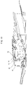
- FIG. 2 is a schematic view showing a general configuration of the ADF, that is, a sheet feeder according to the preferred embodiment of the present invention
- FIGS. 3 and 4 are enlarged explanatory views of the essential parts of the ADF shown in FIG. 2
- FIG. 5 is a graph conceptually illustrating the fluctuation of electric energy converted by a wave receiver since an ultrasonic wave is attenuated due to double feed of the documents in the ADF according to a preferred embodiment of the present invention
- FIGS. 6 and 7 are enlarged views explanatory of the essential parts of the ADF shown in FIG. 2
- FIGS. 8 , 9 and 10 are schematic views showing a general configuration of ADFs according to modifications of the present invention
- FIG. 11 is an enlarged explanatory view of the essential parts of the ADF shown in FIG. 10 .
- the ADF 1 mounted on the above-described image forming apparatus 100 includes a feeding roller 31 for feeding the document, a press roller (press member) 32 for pressing the document against the feeding roller 31 , and a double feed detector 37 for detecting double feed of the documents when the document are fed in superimposition.
- the feeding roller 31 and the press roller 32 are opposed each other at a document holding portion for holding the document to be fed therebetween.
- the double feed detector 37 is placed to be able to detect double feed of the documents in a region being adjacent to the document holding portion, an amplitude of the document being suppressed in the region.
- the ADF 1 is constituted mainly of a document tray 27 on which a stack of documents mounted, a pick-up roller 28 for feeding the document from the stack of documents onto a document feed path S 1 , a document supplying roller 29 and a separating roller 30 for feeding the document downstream of the document feed path S 1 while separating the documents one from another, the plurality of pairs of feeding rollers 31 and press rollers 32 for feeding the document along the document feed path S 1 , a registration roller 33 for feeding the document to a reading portion 34 at a predetermined timing, and a document discharging roller 35 for discharging the document whose image is finished to be read onto a document discharging tray 36 .
- the document tray 27 can be moved in upward and downward directions.
- a sensor not shown, detects that the stack of documents is mounted on the document tray 27 , the document tray 27 is moved upward at a printing request by a user, and then, an uppermost document out of the stack of documents is fed onto the document feed path S 1 by the pick-up roller 28 .
- the separating roller 30 normally eliminates a doubly fed state, and thus, the documents are fed one by one downstream of the document feed path S 1 by the document supplying roller 29 , as described above.
- the ADF 1 since the ADF 1 according to the preferred embodiment of the present invention feeds the document at a high speed so as to cope with the high-speed printing, there is a fear of double feed even with the separating roller 30 .
- the ADF 1 includes the double feed detector 37 in the vicinity of the feeding roller 31 and the press roller 32 disposed downstream of the document supplying roller 29 and the separating roller 30 .
- the double feed detector 37 is constituted of a wave transmitter 38 for transmitting an ultrasonic wave, and a wave receiver 39 for receiving the ultrasonic wave transmitted from the wave transmitter 38 .
- the ultrasonic wave transmitted from the wave transmitter 38 is greatly attenuated due to a slight air layer formed between the superimposed documents D, and then, is received by the wave receiver 39 , to be thus converted into electric energy.
- the level of the electric energy converted by the wave receiver 39 is compared with a predetermined threshold, so that it can be detected as to whether the documents are normally fed one by one or they are abnormally fed in the doubly fed state, as illustrated in FIG. 5 .
- the ultrasonic wave is transmitted via air as a medium, if there is an amplitude, that is, a fluctuation in the document, to which the ultrasonic wave is transmitted, an output from the wave receiver 39 is fluctuated and it is difficult to accurately detect double feed.
- the document approaching the wave receiver 39 while being vibrated applies a vibration on a level higher than usual to the wave receiver 39 via the air staying between the wave receiver 39 and the document so that a sensor in the wave receiver 39 is vibrated more largely than usual when the document ultrasonically vibrated with the application of the ultrasonic wave from the wave transmitter 38 approaches the wave receiver 39 due to the fluctuation, thereby causing the fluctuation of the output from the wave receiver 39 due to the fluctuation in the document.
- the wave transmitter 38 and the wave receiver 39 are disposed so as to detect double feed of the documents in a region R where the amplitude of the document D is suppressed as shown FIG. 6 . That is, since the region R in the document D is defined between the document holding portions held by the plurality of pairs of the feeding rollers 31 and the press rollers 32 arranged in a direction perpendicular to the document feed direction, the amplitude of the document D is suppressed in the region R.
- the wave transmitter 38 and the wave receiver 39 are disposed slantwise with respect to the surface of the document D such that the ultrasonic wave transmitted from the wave transmitter 38 is received by the wave receiver 39 through between the respective shafts of the feeding roller 31 and the pressing roller 32 .
- the wave transmitter 38 irradiates the region R with the ultrasonic wave, and the wave receiver 39 receives the attenuated ultrasonic wave when passing through the region R. Since the region R in the document D is defined between the document holding portions, the amplitude of the document D is suppressed in the region R. Therefore, the wave transmitter 38 and the wave receiver 39 can detect double feed of the documents accurately without being influenced by the fluctuation of the output from the wave receiver due to the amplitude of the document D.
- the wave transmitter 38 and the wave receiver 39 are arranged slantwise with respect to the surface of the document D in such a manner that the ultrasonic wave transmitted from the wave transmitter 38 is received by the wave receiver 39 through between the respective shafts of the feeding roller 31 and the pressing roller 32 .
- the ADF 1 never becomes large even if it is equipped with the double feed detecting function.
- the above-described arrangement enables the double feed detector 37 to be disposed in the vicinity of the various rollers housed inside of the ADF 1 .
- the ADF 1 in the preferred embodiment includes a sub tray 40 for a document made of thick paper or the like having stiffness, as shown in FIG. 2 .
- the document made of thick paper or the like placed on the sub tray 40 is fed onto a substantially straight document feed path S 2 by a pickup roller 41 , and then, is fed while being held between a sheet supplying roller 42 and a separating pad 43 serving as a press member, and reach at the document feed path S 1 .
- Another double feed detector 37 constituted of the wave transmitter 38 and the wave receiver 39 is disposed also in the vicinity of the sheet supplying roller 42 and the separating pad 43 .
- the plurality of pairs of the sheet supplying rollers 42 and the separating pads 43 are arranged in a direction perpendicular to a feed direction of the document D, and the wave transmitter 38 and the wave receiver 39 are interposed between the document holding portions being adjacent to each other, as shown in FIG. 7 .
- the wave transmitter 38 and the wave receiver 39 can detect double feed in the region R where the amplitude of the document is suppressed. That is, the region R in the document D is defined between the document holding portion where the document is held by the plurality pairs of the sheet supplying roller 42 and the separating pad 43 , thus, the amplitude of the document D is suppressed.
- the wave transmitter 38 and the wave receiver 39 can detect double feed of the documents accurately without being influenced by the amplitude of the document D.
- the configuration of the ADF 1 in the preferred embodiment may be modified, as shown in FIGS. 8 and 9 .
- a double feed detector 37 constituted of a wave transmitter 38 and a wave receiver 39 is disposed in the vicinity of a sheet supplying roller 29 and a separating roller 30 .
- a double feed detector 37 constituted of a wave transmitter 38 and a wave receiver 39 is disposed in the vicinity of a registration roller 33 .
- a double feed detector 37 is disposed only in front of a reading unit 34 , in which double feed must never occur. Consequently, the single double feed detector 37 can produce a profound effect.
- a double feed detector 37 constituted of a wave transmitter 38 and a wave receiver 39 may be disposed at a portion, at which a document is held between a feeding roller 31 and a rib 44 serving as a press member on the way of a document feed path S 1 , as shown in FIGS. 10 and 11 .
- the double feed detector is disposed in such a manner as to detect double feed of the sheets in the region, in which the amplitude of the sheet is suppressed, adjacent to the sheet holding portion, thereby securely detecting double feed of the sheets while feeding the sheet at a high speed.
- double feed of the sheets can be securely detected irrespective of the position of the double feed detector as long as the sheet is held between the feeding roller and the press member, with an attendant advantage of a very high freedom of a design.
- the double feed detector is disposed only in the ADF in the above-described preferred embodiment, the double feed detector may be disposed at the sheet supplying roller, the feeding roller, the registration roller or the like in the image forming apparatus in the same manner.
Landscapes
- Controlling Sheets Or Webs (AREA)
Applications Claiming Priority (2)
| Application Number | Priority Date | Filing Date | Title |
|---|---|---|---|
| JP2006-106623 | 2006-04-07 | ||
| JP2006106623A JP4410212B2 (ja) | 2006-04-07 | 2006-04-07 | 用紙搬送装置 |
Publications (2)
| Publication Number | Publication Date |
|---|---|
| US20070235922A1 US20070235922A1 (en) | 2007-10-11 |
| US7654522B2 true US7654522B2 (en) | 2010-02-02 |
Family
ID=38574386
Family Applications (1)
| Application Number | Title | Priority Date | Filing Date |
|---|---|---|---|
| US11/783,076 Expired - Fee Related US7654522B2 (en) | 2006-04-07 | 2007-04-05 | Sheet feeder with ultrasonic double feed detector |
Country Status (3)
| Country | Link |
|---|---|
| US (1) | US7654522B2 (zh) |
| JP (1) | JP4410212B2 (zh) |
| CN (1) | CN101049876B (zh) |
Cited By (9)
| Publication number | Priority date | Publication date | Assignee | Title |
|---|---|---|---|---|
| US20070237430A1 (en) * | 2006-04-10 | 2007-10-11 | Nisca Corporation | Sheet conveying device and sheet feeding device comprising the same, and image processing apparatus |
| US20120269566A1 (en) * | 2011-04-20 | 2012-10-25 | Seiko Epson Corporation | Image processing device and sheet feeding mechanism |
| US20130069299A1 (en) * | 2011-09-20 | 2013-03-21 | Hiroki Matsuoka | Sheet transport apparatus and sheet transport method |
| US20130134655A1 (en) * | 2011-11-30 | 2013-05-30 | Daisuke Nakayama | Sheet Conveyer |
| US20160159597A1 (en) * | 2014-12-08 | 2016-06-09 | Brother Kogyo Kabushiki Kaisha | Sheet conveyer device |
| US20190187605A1 (en) * | 2017-12-14 | 2019-06-20 | Konica Minolta, Inc. | Sheet type determining device and image forming device |
| US10689216B2 (en) * | 2018-03-15 | 2020-06-23 | Kabushiki Kaisha Toshiba | Inspection device and inspection method |
| US20210155430A1 (en) * | 2019-11-27 | 2021-05-27 | Canon Kabushiki Kaisha | Sheet conveying apparatus and image reading apparatus |
| US11736640B1 (en) * | 2022-08-22 | 2023-08-22 | Kyocera Document Solutions, Inc. | Method and apparatus for detecting sheet-fed scanner double-feeds using neural network classifier |
Families Citing this family (7)
| Publication number | Priority date | Publication date | Assignee | Title |
|---|---|---|---|---|
| JP4812114B2 (ja) * | 2007-02-23 | 2011-11-09 | オムロン株式会社 | 紙葉類重送検知装置及び紙葉類重送検知方法 |
| JP4446002B2 (ja) * | 2008-01-28 | 2010-04-07 | シャープ株式会社 | 用紙搬送装置、これを備えた画像形成装置、用紙搬送方法、用紙搬送プログラム、及びこのプログラムを記録したコンピュータ読取可能な記録媒体 |
| JP5770848B2 (ja) | 2011-06-29 | 2015-08-26 | キヤノン電子株式会社 | 重送検知装置、及びシート搬送装置、並びにシート処理装置 |
| JP6372223B2 (ja) * | 2014-07-28 | 2018-08-15 | 富士ゼロックス株式会社 | 記録シートの搬送装置及び画像読取装置 |
| JP2016084207A (ja) | 2014-10-24 | 2016-05-19 | キヤノン株式会社 | シート搬送装置及び画像形成装置 |
| JP7211211B2 (ja) * | 2019-03-29 | 2023-01-24 | コニカミノルタ株式会社 | シート搬送装置、画像読み取り装置および画像形成装置 |
| JP7287192B2 (ja) * | 2019-08-30 | 2023-06-06 | セイコーエプソン株式会社 | 媒体搬送装置、画像読取装置、及び、媒体搬送装置における媒体検知方法 |
Citations (4)
| Publication number | Priority date | Publication date | Assignee | Title |
|---|---|---|---|---|
| JPS6468349A (en) | 1987-08-24 | 1989-03-14 | Ibm | Production of iodonium triflate and sulfonium triflate |
| US20030006550A1 (en) * | 2001-06-15 | 2003-01-09 | Omron Corporation | Sheet double feeding detector, method and program of such a device |
| JP2005162426A (ja) | 2003-12-04 | 2005-06-23 | Nisca Corp | シート重送検出方法及びシート供給装置並びに画像読取装置 |
| US20050189707A1 (en) * | 2003-12-04 | 2005-09-01 | Kazuhide Sano | Sheet feeding apparatus and image reading apparatus equipped with the same |
-
2006
- 2006-04-07 JP JP2006106623A patent/JP4410212B2/ja active Active
-
2007
- 2007-04-05 US US11/783,076 patent/US7654522B2/en not_active Expired - Fee Related
- 2007-04-06 CN CN2007100910806A patent/CN101049876B/zh not_active Expired - Fee Related
Patent Citations (4)
| Publication number | Priority date | Publication date | Assignee | Title |
|---|---|---|---|---|
| JPS6468349A (en) | 1987-08-24 | 1989-03-14 | Ibm | Production of iodonium triflate and sulfonium triflate |
| US20030006550A1 (en) * | 2001-06-15 | 2003-01-09 | Omron Corporation | Sheet double feeding detector, method and program of such a device |
| JP2005162426A (ja) | 2003-12-04 | 2005-06-23 | Nisca Corp | シート重送検出方法及びシート供給装置並びに画像読取装置 |
| US20050189707A1 (en) * | 2003-12-04 | 2005-09-01 | Kazuhide Sano | Sheet feeding apparatus and image reading apparatus equipped with the same |
Cited By (18)
| Publication number | Priority date | Publication date | Assignee | Title |
|---|---|---|---|---|
| US20070237430A1 (en) * | 2006-04-10 | 2007-10-11 | Nisca Corporation | Sheet conveying device and sheet feeding device comprising the same, and image processing apparatus |
| US8500119B2 (en) * | 2006-04-10 | 2013-08-06 | Nisca Corporation | Sheet conveying device and image processing apparatus |
| US20120269566A1 (en) * | 2011-04-20 | 2012-10-25 | Seiko Epson Corporation | Image processing device and sheet feeding mechanism |
| US8882373B2 (en) * | 2011-04-20 | 2014-11-11 | Seiko Epson Corporation | Image processing device and sheet feeding mechanism |
| US8657285B2 (en) * | 2011-09-20 | 2014-02-25 | Pfu Limited | Sheet transport apparatus and sheet transport method |
| US20130069299A1 (en) * | 2011-09-20 | 2013-03-21 | Hiroki Matsuoka | Sheet transport apparatus and sheet transport method |
| US9051143B2 (en) | 2011-11-30 | 2015-06-09 | Brother Kogyo Kabushiki Kaisha | Sheet conveyer and image reading apparatus |
| US8636284B2 (en) * | 2011-11-30 | 2014-01-28 | Brother Kogyo Kabushiki Kaisha | Sheet conveyer |
| US20130134655A1 (en) * | 2011-11-30 | 2013-05-30 | Daisuke Nakayama | Sheet Conveyer |
| US20160159597A1 (en) * | 2014-12-08 | 2016-06-09 | Brother Kogyo Kabushiki Kaisha | Sheet conveyer device |
| US9873580B2 (en) * | 2014-12-08 | 2018-01-23 | Brother Kogyo Kabushiki Kaisha | Sheet conveyer device |
| US20190187605A1 (en) * | 2017-12-14 | 2019-06-20 | Konica Minolta, Inc. | Sheet type determining device and image forming device |
| US10894689B2 (en) * | 2017-12-14 | 2021-01-19 | Konica Minolta, Inc. | Sheet type determining device and image forming device |
| US10689216B2 (en) * | 2018-03-15 | 2020-06-23 | Kabushiki Kaisha Toshiba | Inspection device and inspection method |
| US20210155430A1 (en) * | 2019-11-27 | 2021-05-27 | Canon Kabushiki Kaisha | Sheet conveying apparatus and image reading apparatus |
| US11807490B2 (en) * | 2019-11-27 | 2023-11-07 | Canon Kabushiki Kaisha | Sheet conveying apparatus and image reading apparatus |
| US20240025684A1 (en) * | 2019-11-27 | 2024-01-25 | Canon Kabushiki Kaisha | Sheet conveying apparatus and image reading apparatus |
| US11736640B1 (en) * | 2022-08-22 | 2023-08-22 | Kyocera Document Solutions, Inc. | Method and apparatus for detecting sheet-fed scanner double-feeds using neural network classifier |
Also Published As
| Publication number | Publication date |
|---|---|
| CN101049876B (zh) | 2010-05-26 |
| CN101049876A (zh) | 2007-10-10 |
| US20070235922A1 (en) | 2007-10-11 |
| JP4410212B2 (ja) | 2010-02-03 |
| JP2007276965A (ja) | 2007-10-25 |
Similar Documents
| Publication | Publication Date | Title |
|---|---|---|
| US7654522B2 (en) | Sheet feeder with ultrasonic double feed detector | |
| US7822376B2 (en) | Sheet feeder and copying machine including the same | |
| US7690650B2 (en) | Sheet transporting device, and automatic document feeder and image forming apparatus provided with the same | |
| EP2098466B1 (en) | Sheet feeding apparatus and image reading apparatus | |
| US9420141B2 (en) | Position adjustment apparatus of imaging unit, the imaging unit, and image reading apparatus including the imaging unit | |
| US8205883B2 (en) | Paper transport path of image forming apparatus | |
| US7672630B2 (en) | Image forming apparatus and image forming method with improved cleaning mechanism | |
| JP5726130B2 (ja) | 折り装置、後処理装置及び画像形成装置 | |
| US10901356B2 (en) | Image-forming apparatus and recording material identification unit | |
| US7384032B2 (en) | Sheet feeding apparatus, image reading apparatus, and image forming apparatus | |
| US8457517B2 (en) | Image forming apparatus and transfer roller bias system | |
| JP7166826B2 (ja) | 画像読取装置及び画像形成装置 | |
| JP2006347645A (ja) | 画像形成装置 | |
| US20110262168A1 (en) | Fixing device, image forming apparatus, and image forming method | |
| JP4491436B2 (ja) | 用紙搬送装置 | |
| JP2008007277A (ja) | 用紙搬送装置、画像形成装置、及び原稿読取り装置 | |
| US8630570B2 (en) | Transfer device, image forming apparatus, and image forming method | |
| US20190250549A1 (en) | Image forming apparatus | |
| JP2008063101A (ja) | 用紙搬送方法およびその方法を利用した原稿読取装置 | |
| JP2020086208A (ja) | 媒体厚検出装置、媒体搬送装置および画像形成装置 | |
| JP2005269601A (ja) | 原稿搬送読取装置および画像形成装置 | |
| US11634290B2 (en) | Sheet conveyance apparatus and image forming apparatus | |
| JP5950787B2 (ja) | シート押さえ機構、シート搬送装置、画像処理装置 | |
| JP2006016094A (ja) | 画像形成装置の用紙搬送装置 | |
| JP2008124623A (ja) | 画像読取装置、及び画像形成装置 |
Legal Events
| Date | Code | Title | Description |
|---|---|---|---|
| AS | Assignment |
Owner name: SHARP KABUSHIKI KAISHA,JAPAN Free format text: ASSIGNMENT OF ASSIGNORS INTEREST;ASSIGNOR:TONAMI, KAZUMASA;REEL/FRAME:019212/0892 Effective date: 20070309 Owner name: SHARP KABUSHIKI KAISHA, JAPAN Free format text: ASSIGNMENT OF ASSIGNORS INTEREST;ASSIGNOR:TONAMI, KAZUMASA;REEL/FRAME:019212/0892 Effective date: 20070309 |
|
| STCF | Information on status: patent grant |
Free format text: PATENTED CASE |
|
| FPAY | Fee payment |
Year of fee payment: 4 |
|
| FEPP | Fee payment procedure |
Free format text: PAYOR NUMBER ASSIGNED (ORIGINAL EVENT CODE: ASPN); ENTITY STATUS OF PATENT OWNER: LARGE ENTITY |
|
| FPAY | Fee payment |
Year of fee payment: 8 |
|
| FEPP | Fee payment procedure |
Free format text: MAINTENANCE FEE REMINDER MAILED (ORIGINAL EVENT CODE: REM.); ENTITY STATUS OF PATENT OWNER: LARGE ENTITY |
|
| LAPS | Lapse for failure to pay maintenance fees |
Free format text: PATENT EXPIRED FOR FAILURE TO PAY MAINTENANCE FEES (ORIGINAL EVENT CODE: EXP.); ENTITY STATUS OF PATENT OWNER: LARGE ENTITY |
|
| STCH | Information on status: patent discontinuation |
Free format text: PATENT EXPIRED DUE TO NONPAYMENT OF MAINTENANCE FEES UNDER 37 CFR 1.362 |
|
| FP | Lapsed due to failure to pay maintenance fee |
Effective date: 20220202 |