US7484455B2 - Pasta cooking device and method - Google Patents
Pasta cooking device and method Download PDFInfo
- Publication number
- US7484455B2 US7484455B2 US10/519,703 US51970304A US7484455B2 US 7484455 B2 US7484455 B2 US 7484455B2 US 51970304 A US51970304 A US 51970304A US 7484455 B2 US7484455 B2 US 7484455B2
- Authority
- US
- United States
- Prior art keywords
- basket
- bowl
- cooking device
- water
- base
- Prior art date
- Legal status (The legal status is an assumption and is not a legal conclusion. Google has not performed a legal analysis and makes no representation as to the accuracy of the status listed.)
- Expired - Fee Related, expires
Links
Images




Classifications
-
- A—HUMAN NECESSITIES
- A47—FURNITURE; DOMESTIC ARTICLES OR APPLIANCES; COFFEE MILLS; SPICE MILLS; SUCTION CLEANERS IN GENERAL
- A47J—KITCHEN EQUIPMENT; COFFEE MILLS; SPICE MILLS; APPARATUS FOR MAKING BEVERAGES
- A47J27/00—Cooking-vessels
- A47J27/10—Cooking-vessels with water-bath arrangements for domestic use
-
- A—HUMAN NECESSITIES
- A47—FURNITURE; DOMESTIC ARTICLES OR APPLIANCES; COFFEE MILLS; SPICE MILLS; SUCTION CLEANERS IN GENERAL
- A47J—KITCHEN EQUIPMENT; COFFEE MILLS; SPICE MILLS; APPARATUS FOR MAKING BEVERAGES
- A47J27/00—Cooking-vessels
- A47J27/004—Cooking-vessels with integral electrical heating means
-
- A—HUMAN NECESSITIES
- A47—FURNITURE; DOMESTIC ARTICLES OR APPLIANCES; COFFEE MILLS; SPICE MILLS; SUCTION CLEANERS IN GENERAL
- A47J—KITCHEN EQUIPMENT; COFFEE MILLS; SPICE MILLS; APPARATUS FOR MAKING BEVERAGES
- A47J37/00—Baking; Roasting; Grilling; Frying
- A47J37/12—Deep fat fryers, e.g. for frying fish or chips
- A47J37/1219—Deep fat fryers, e.g. for frying fish or chips with means for lowering or raising the frying basket
Definitions
- the present invention refers to a cooking device and procedure.
- the devices of the conventional type have numerous drawbacks which can be summed up as the following.
- the use of burners, often gas-fired, can be dangerous in particular when the pan is not watched over.
- An unforeseen bubbling over of water or froth from the pan could, indeed, put out the flame without interrupting the gas supply.
- the consequences in this case are easy to imagine.
- the technical task or object of the present invention is, therefore, that of providing a cooking device and procedure which allow the aforementioned technical drawbacks of the prior art to be eliminated.
- an object of the invention is that of providing a cooking device which can function, in complete safety and ensuring the quality of the food cooked, without the presence of a user being necessary to continuously watch over and/or actively operate, for example stirring the food.
- Another object of the invention is that of providing a device which is very safe and which, in particular, does not require the use of flammable gas.
- the last but not least object of the invention is that of providing a device and a procedure which allow various types of food, in particular pasta, to be cooked in an optimal manner, also when the user has very limited cooking experience and even allows people without any experience at all to cook pasta and other food in an optimal manner.
- a cooking device characterized in that it comprises a base which carries a bowl with electrical heating means and containing a basket for containing food to be cooked, this basket being connected to drive means suitable for moving it between a lower position inside the bowl and an upper position at least partially outside of it, the device also comprising a first sensor of the temperature of at least a portion of the bowl and a timer connected to means for controlling the drive means, for moving the basket, in response to signals that the control means receives from the temperature sensor and from the timer.
- the present invention also refers to a procedure for cooking through a device according to the invention where the heating means heats the water contained in the bowl taking it up to a predetermined temperature, at which point the first sensor detects that such a predetermined temperature has been reached and the basket is plunged into the water and, at the same time, the timer is started for a preset time period, at the end of which the control means deactivates the heating means and initiates the removal of the basket from the bowl.
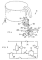
- FIG. 1 shows a cross-section of the device according to the present invention
- FIG. 2 shows a partial section perspective view of the device according to the invention
- FIG. 3 shows a detail of a different embodiment of the device
- FIG. 4 shows a diagram of the device with control and drive means of the electromechanical type
- FIG. 5 shows a circuit diagram of the device of FIG. 4 ;
- FIG. 6 shows a partial section view of a device equipped with an anti-rotation element for the pasta.
- FIG. 7 shows a drive element
- the device 1 comprises a base 2 which carries a bowl 3 having electrical heating means 4 , for example consisting of shielded resistances, and containing a basket 5 for containing the food to be cooked.
- the basket 5 is connected to drive means 6 suitable for moving it between a lower position inside the bowl and an upper position at least partially outside of it.
- the device also comprises a first sensor 7 of the temperature of at least a portion of the bowl and a timer 8 connected to control means 9 (for example formed by a circuit board or else electromechanically) which, in turn, are connected to the drive means 6 so as to move the basket 5 in response to the signals which the control means 9 receives from the temperature sensor 7 and from the timer 8 , between the lower position inside the bowl 3 and the upper position at least partially outside of it.
- control means 9 for example formed by a circuit board or else electromechanically
- the device 1 comprises means 10 for stirring the food contained inside the basket 5 which is also connected to the control means 9 .
- the mixing means 10 comprises an element 11 rotatably connected to the basket 5 and removably connected to a drive element 12 which protrudes from the base 2 and is connected to a first motor 13 .
- the rotatable element 11 comprises a disk, for example with a grid, FIG. 1 ) substantially conical, from which protruding paddles 11 a extend, and having a widened central portion 14 rotatably connected in a through-seat 15 formed on the base of the basket 5 .
- the widened central portion 14 defines a socket or is seat 16 suitable for receiving a portion of the drive element 12 .
- the rotatable element 11 comprises an arm from which the protruding paddles 11 a extend.
- the rotatable element 11 has the central portion 14 raised and rotatably connected in the through-seat 15 formed on the base of the basket 5 .
- the raised central portion 14 defines the seat 16 suitable for receiving a portion of the drive element 12 .
- the drive means comprises a support for the basket 17 which has a rack 18 operatively connected to a pinion 19 capable of being actuated through a second motor 20 , which is connected to the control means 9 .
- the device 1 comprises at least one second sensor 21 suitable for detecting the position of the basket 5 , for example consisting of a microswitch, a photocell or a magnetic sensor.
- the bowl 3 is removably connected to the base 2 , i.e. so that it can be taken out of it and put back in. In this way the bowl 3 can be removed for easy emptying of the water and cleaning.
- the device 1 comprises at least a third sensor 22 of the presence of the bowl 3 and a closing cover 23 applied above the basket 5 to allow the basket 5 itself to be moved without hindrance from the cover 23 .
- the cover 23 comprises at least one anti-foaming hatch (not shown for the sake of simplicity in the attached figures), free to oscillate from an open position to a closed position and vice-versa when the pressure inside the bowl 3 exceeds a predetermined value.
- the hatch 20 makes it also possible to monitor the progression of the cooking of the pasta or else to pick out a piece of pasta to taste it and check how much it is cooked, in the case in which one prefers pasta which is more or less cooked with respect to the optimal cooking instructions.
- the cover 23 has a central hole in which a container 24 is housed suspended in the basket 5 .
- the container 23 is used for the sauce, so as to heat or cook the sauce at the same time as the pasta.
- the device is also equipped with a control panel (not represented for the sake of simplicity), which allows the cooking times to be programmed and detected even in the time span of 24 hours. In this way it is possible to freely set the moment when one wishes to have the pasta drained.
- a control panel not represented for the sake of simplicity
- the timer shows the time of day and functions as a clock.
- the operation of the cooking device 1 according to the invention is clear from that which has been described and illustrated and, in particular, is substantially as described in the following.
- the bowl 3 is filled with salted water, the pasta is inserted into the basket 5 which is in raised or upper position and the cooking time of the pasta is set. Then the device is switched on and the water is heated so that it boils.
- the boiling temperature is recognized when the sensor 7 detects, after switching on, a stable temperature below a predetermined temperature.
- the control means 9 commands the lowering of the basket 5 and the starting of the timer 8 . At the same time a sound is also emitted through a buzzer (not represented).
- control means 9 actuates the motor 13 of the stirring means 10 , to prevent the pasta from sticking.
- control means 9 cyclically activates and deactivates the heating means 4 and stirring means 10 , so as to reduce the energy transmitted to the water and to obtain a less turbulent boiling movement of the water, thereby producing less foam and obtaining a better stirring.
- the buzzer is again activated by the control means 9 and emits an other sound.
- the cooking proceeds until the timer 8 , when it detects the end of the set time, sends a signal to the control means 9 which deactivates the heating means 4 and lifts the basket 5 .
- the control means 9 activates the heating means 3 at the set time, the control means checks (through the temperature sensor 7 ) the increase in temperature of the water (which depends upon the amount of water to be heated) and, in the case in which it is too quick, it interrupts the power supply to the electric means and calculates the waiting time before starting to heat again. Then the whole thing is carried out as described previously, with the heating means which takes the water to a temperature close to boiling and the basket which is lowered into the water for the cooking of the pasta and, when cooking is complete, it is removed.
- the present invention also refers to a procedure for cooking with a device of the type described previously.
- the sensor 7 also functions as a safety element since when it detects a temperature higher than a safety temperature it interrupts the operation of the device.
- the heating means 4 heats the water contained in the bowl 3 up to a predetermined temperature, for example close to boiling.
- the first sensor 7 detects that such a predetermined temperature has been reached the basket 5 is lowered into the water and, at the same time, the timer 8 is started for a preset period of time.
- the control means 9 deactivates the heating means 4 and removes the basket 5 from the bowl 3 .
- the stirring means 10 is actuated.
- the heating means 4 and/or stirring means 10 are activated discontinuously, so as to reduce the power, to reduce the turbulence of the water and to reduce the production of foam.
- FIGS. 4 and 5 show a different embodiment of the device 1 in which the control means 9 and the drive means 6 are of the electromechanical type.
- an electromechanical timer 25 connected to the device 1 has a toothed portion 26 and two portions equipped with cams, a first cam 27 which protrudes and a second cam 28 which is grooved.
- the toothed portion 26 is associated with an arm 29 which has a toothed end kept in contact with the toothed portion 26 by a counter spring 30 , and another end connected to a microswitch 31 .
- the teeth of the portion 26 are of the type which allows the toothed portion 26 and the arm 29 to be locked when the timer turns in one direction (i.e. preventing rotation of the timer in one direction) whereas it allows the sliding of the teeth past the arm in the opposite direction (therefore, for example, when the arm 29 and the toothed portion 26 are connected to each other the timer can rotate only in counterclockwise direction, as indicated by the arrow F).
- the microswitch 31 is in the path of the rack 18 , so that the rack 18 , during its motion downward (to lower the basket 5 ), actuates the microswitch 31 which interrupts the power supply to the motor 20 and locks the basket 5 inside the bowl 3 sunk in the water.
- the cam 27 serves for actuating the microswitch 32 (the microswitch 32 is closed when it is connected to the cam) which turns on the power supply to the motor 20 and thus lifts the basket 5 .
- the cam 27 when the cam 27 is connected to the microswitch 32 it closes the electric circuit of the device whereas when the cam 27 is not connected to the microswitch 32 (for example when the timer is set to cook pasta) the electric circuit of the device is open.
- the grooved cam 28 is associated with a pin 33 connected to a further microswitch 34 .
- the microswitch 34 serves for connection to a protruding portion 35 of the rack 18 so that, when the pin 33 is inserted in the grooved cam 28 and the basket is in upper position, the microswitch 34 is connected to the portion 35 of the rack 18 and the electric circuit of the device is open, whereas when the pin 33 is in contact with the cylindrical drum outside of the grooved cam 28 , the microswitch 34 is not connected to the portion 35 and the electric circuit of the device 1 is closed.
- FIG. 5 schematically shows the electric circuit of the device.
- the configuration of the switches is the one shown in solid lines (microswitch 31 closed, microswitch 32 closed, microswitch 34 open, sensor 7 open, the sensor 7 being of the THS type and being suitable for operating as a switch controlled by the temperature detected).
- microswitch 32 When the timer 25 is set the power supply to the heating means 3 and to the motor for the shaft 13 begins.
- the microswitch 32 is closed, the microswitch 31 remains closed (with the arm 29 which keeps the timer 25 locked) and the microswitch 34 is closed (since it is taken away from the portion 35 ), (microswitch 31 closed, microswitch 32 open, microswitch 34 closed, sensor 7 open).
- the temperature increases until, when around boiling temperature is reached, the sensor 7 closes and feeds electricity from the power supply to the motor 20 (through the microswitch 31 and 34 ) which lowers the basket into the bowl 3 (microswitch 31 closed, microswitch 32 open, microswitch 34 closed, sensor 7 closed).
- the rack 18 During downward motion the rack 18 meets the microswitch 31 , opens it (interrupting the flow of current) and stops the basket 5 inside the bowl 3 (microswitch 31 open, microswitch 32 open, microswitch 34 closed, sensor 7 closed). At the same time the rack 18 displaces the arm 29 , moving it away from the toothed portion 26 and allowing the start of the counting by the timer of the cooking time of the pasta. During the counting of the timer 25 , the cams 27 and 28 rotate.
- microswitch 34 When during lifting the portion 35 opens the microswitch 34 , the power supply to the motor 20 is interrupted and the basket 5 remains suspended on the bowl 3 out of the water (the microswitches go back into the starting configuration—microswitch 31 closed, microswitch 32 closed, microswitch 34 open).
- FIGS. 3 and 6 show another embodiment of the device according to the invention equipped with anti-rotation means 36 for the pasta.
- the anti-rotation means 36 comprises a fixed anti-rotation element connected to a fixed part of the device 1 and inserted inside the basket 5 and the bowl 3 .
- a fixed anti-rotation element 36 has an end placed between the paths of the paddles 11 a and has a portion connected to the top of the support 2 and forming a handle.
- the space taken up by spaghetti is also represented, wholly indicated with reference numeral 37 .
- the stirring means 10 such as the shaft
- the anti-rotation means prevents the pasta from rotating together with it and ensures excellent stirring.
- FIG. 7 shows a drive element 12 comprising a pin guide 38 slidably connected to the basket 5 and having an inner hole 39 which is at least partially faceted and a threaded lower portion 40 .
- a drive pin 41 is inserted into the hole 39 (without the possibility of rotating).
- the pin 41 has a faceted portion 42 and two grooves 43 which house seals (not shown).
- the lower part 44 of the pin is widened and is coated in Teflon to promote sliding.
- the pin 41 at the bottom, has an outer edge flange 45 and a blade 46 suitable for connecting to a connection element 47 of the motor 13 .
- the pin 41 is connected to the pin guide 38 (and thus to the basket 5 ) by the nut 48 .
- the connection element 47 comprises a disk 49 which has four protruding pins 50 (for example with a triangular section) and a square hole in which the drive shaft 52 (also square) of the motor 13 is slidably inserted. Moreover, a spring 53 , which allows gaps to be closed, is placed between the case of the motor 13 and the disk 49 . When the basket 5 is lowered the blade 46 fits between the pins 50 and ensures the connection and the actuation of the stirring means 10 . If the blade 46 locks above the pins 50 the rotation of the disk 49 and the push of the spring 53 take the drive element 12 back to correct configuration.
- the cooking device and procedure according to the invention are particularly advantageous because they allow the cooking of pasta in particular, but also other dishes, without the need for it to be watched over continuously and always ensuring optimal results.
- the device according to the present invention also allows rice, custard, mousses, soups, polenta, etc. to be cooked.
- the device can also be used for steam-cooking food.
- the cooking device and procedure thus conceived are susceptible of numerous modifications and variants, all covered by the inventive concept. Moreover, all of the details can be replaced with technically equivalent elements.
- the materials used, as well as the sizes can be whatever according to the requirements and the state of the art.
Landscapes
- Engineering & Computer Science (AREA)
- Food Science & Technology (AREA)
- Commercial Cooking Devices (AREA)
- Noodles (AREA)
- Vending Machines For Individual Products (AREA)
- Food-Manufacturing Devices (AREA)
- Cookers (AREA)
Applications Claiming Priority (3)
| Application Number | Priority Date | Filing Date | Title |
|---|---|---|---|
| ITM12002A001431 | 2002-06-28 | ||
| IT2002MI001431A ITMI20021431A1 (it) | 2002-06-28 | 2002-06-28 | Dispositivo e procedimento di cottura |
| PCT/EP2003/003532 WO2004002280A1 (en) | 2002-06-28 | 2003-04-04 | Cooking device and procedure |
Publications (2)
| Publication Number | Publication Date |
|---|---|
| US20050229789A1 US20050229789A1 (en) | 2005-10-20 |
| US7484455B2 true US7484455B2 (en) | 2009-02-03 |
Family
ID=11450106
Family Applications (1)
| Application Number | Title | Priority Date | Filing Date |
|---|---|---|---|
| US10/519,703 Expired - Fee Related US7484455B2 (en) | 2002-06-28 | 2003-04-04 | Pasta cooking device and method |
Country Status (8)
| Country | Link |
|---|---|
| US (1) | US7484455B2 (de) |
| EP (1) | EP1517631B1 (de) |
| CN (1) | CN1305424C (de) |
| AT (1) | ATE338498T1 (de) |
| AU (1) | AU2003229606A1 (de) |
| DE (1) | DE60308184T2 (de) |
| IT (1) | ITMI20021431A1 (de) |
| WO (1) | WO2004002280A1 (de) |
Cited By (12)
| Publication number | Priority date | Publication date | Assignee | Title |
|---|---|---|---|---|
| US20070119443A1 (en) * | 2003-12-23 | 2007-05-31 | De Longhi Giuseppe | Fryer |
| US20100058939A1 (en) * | 2008-09-09 | 2010-03-11 | Adrian Rivera | Automated Juice Extractor |
| US20100212511A1 (en) * | 2009-02-20 | 2010-08-26 | Frymaster L.L.C. | Racking system for deep fryer |
| US20110011278A1 (en) * | 2009-07-15 | 2011-01-20 | Frymaster L.L.C | Automated rack/basket lifting system for deep open vat frying system |
| US20110048246A1 (en) * | 2009-08-27 | 2011-03-03 | Kuei-Tang Chang | Inner pot assembly for hot-air baking oven and hot-air baking oven having such assembly |
| USD711183S1 (en) * | 2013-01-26 | 2014-08-19 | Joshua Bernheim | Water basin for cooking |
| US9060642B1 (en) | 2012-08-15 | 2015-06-23 | Jeffrey Armbrust | Modular cooking and steaming system |
| USD740070S1 (en) * | 2013-07-10 | 2015-10-06 | Koninklijke Philips N.V. | Pan for airfryer |
| US9655467B1 (en) | 2015-05-05 | 2017-05-23 | Benjamin Martin | Pasta-cooking device |
| US20170251858A1 (en) * | 2016-03-04 | 2017-09-07 | CE Brands, LLC | Smart slow cooker |
| USD834889S1 (en) * | 2017-06-22 | 2018-12-04 | Nuwave, Llc | Air fryer basket |
| US11026536B2 (en) | 2018-01-22 | 2021-06-08 | Innovo Concepts, LLC | Self-contained electronic boiling and straining system |
Families Citing this family (22)
| Publication number | Priority date | Publication date | Assignee | Title |
|---|---|---|---|---|
| FR2887418B1 (fr) * | 2005-06-22 | 2007-08-03 | Seb Sa | Cuiseur a panier de cuisson, comportant un systeme pour eviter la formation de mousse |
| FR2887419A1 (fr) | 2005-06-22 | 2006-12-29 | Seb Sa | Cuiseur a panier de cuisson, comportant un systeme de remuage des aliments |
| FR2887420B1 (fr) * | 2005-06-22 | 2007-07-27 | Seb Sa | Cuiseur a panier de cuisson mobile, comportant un detecteur de debut de cuisson |
| US20070028780A1 (en) * | 2005-08-08 | 2007-02-08 | Popeil Ronald M | Cooking device to deep fat fry foods |
| FR2896677B1 (fr) * | 2006-02-01 | 2010-08-20 | Seb Sa | Appareil de cuisson avec moyen de remuage et procede afferent |
| GB2443478B (en) * | 2006-10-31 | 2009-03-18 | Jeffrey Richard Hewitt | Spaghetti cooking aid |
| US20080223220A1 (en) * | 2007-03-17 | 2008-09-18 | Zheng Peng | Popcorn maker |
| CA2698857C (en) | 2009-04-04 | 2017-08-29 | Kurt H. Roth | Improved food steaming method and apparatus |
| IT1396656B1 (it) * | 2009-05-06 | 2012-12-14 | Fedeli | Macchina per la preparazione espressa di cibi finiti, quali pastasciutta e simili |
| EP2407066B1 (de) * | 2010-07-16 | 2013-09-11 | Kurt H. Roth | Verbessertes Verfahren und Vorrichtung zum Dünsten von Lebensmitteln |
| ES2393378B1 (es) * | 2011-06-07 | 2013-10-31 | Electrodomésticos Taurus, S.L. | Encimera de cocina con medios de accionamiento giratorio y recipiente de cocina utilizable con dicha encimera |
| FR2982753B1 (fr) * | 2011-11-21 | 2013-11-22 | Seb Sa | Appareil electromenager de preparation culinaire comportant un recipient de travail comprenant un panier pour la cuisson a la vapeur |
| WO2014019018A1 (en) * | 2012-07-31 | 2014-02-06 | Breville Pty Limited | Sous vide device |
| CN103892690A (zh) * | 2012-12-27 | 2014-07-02 | 郭雯婷 | 具有电动旋动煮饺装置的电饭锅 |
| DE102015003390B4 (de) * | 2014-12-04 | 2021-01-07 | Küppersbusch Großküchentechnik GmbH & Co. KG | Fritteuse und Verfahren zur Steuerung einer Fritteuse |
| CN105725727A (zh) * | 2016-03-30 | 2016-07-06 | 苏州合欣美电子科技有限公司 | 一种电控烧锅 |
| CN105725725A (zh) * | 2016-03-30 | 2016-07-06 | 苏州合欣美电子科技有限公司 | 一种智能升降式电控烧锅 |
| FR3064168B1 (fr) * | 2017-03-22 | 2019-03-22 | Seb S.A. | Appareil de cuisson muni d'un mecanisme a bras articules |
| GB2566720A (en) * | 2017-09-22 | 2019-03-27 | Kenwood Ltd | Attachment for a kitchen machine |
| US20200397177A1 (en) * | 2019-06-20 | 2020-12-24 | Midea Group Co., Ltd. | Container including agitator for microwave sous vide function |
| CN113197493B (zh) * | 2021-06-16 | 2022-11-15 | 四川鹅全食食品有限责任公司 | 一种鸡蛋批量搅拌装置 |
| DE102021123647A1 (de) | 2021-09-13 | 2023-03-16 | Simon Best | Elektrischer Wassererhitzer zum Erwärmen und Garen von Nahrungsmitteln |
Citations (7)
| Publication number | Priority date | Publication date | Assignee | Title |
|---|---|---|---|---|
| US4951558A (en) | 1989-04-03 | 1990-08-28 | Figliuzzi Vincent D | Basket lifting mechanism for cooking pot |
| US5010805A (en) | 1989-09-13 | 1991-04-30 | Ferrara Daniel A | Potato chip maker including apparatus for centrifugally removing cooking oil from any product |
| EP0716827A1 (de) | 1994-12-16 | 1996-06-19 | The Frymaster Corporation | Alarmanlage zum Angeben, dass ein Produkt vorzeitig herausgenommen wurde |
| US5590583A (en) | 1995-01-13 | 1997-01-07 | Pmi International Corporation | Appliance for making bread and for cooking bagels |
| US5611265A (en) | 1996-09-13 | 1997-03-18 | Ronci; Fernando F. | Combination charbroiler and fryer with spinning food basket |
| US7026591B2 (en) * | 2001-10-17 | 2006-04-11 | De' Longhi S.P.A. | Device and procedure for cooking a food product with microwaves |
| US7105780B2 (en) * | 2003-06-06 | 2006-09-12 | De'longhi S.P.A. | Cooking device and procedure |
Family Cites Families (2)
| Publication number | Priority date | Publication date | Assignee | Title |
|---|---|---|---|---|
| US4649810A (en) * | 1985-08-22 | 1987-03-17 | Wong Don M | Automatic cooking apparatus |
| CN2418792Y (zh) * | 2000-04-21 | 2001-02-14 | 林保宏 | 自动搅拌烹煮机 |
-
2002
- 2002-06-28 IT IT2002MI001431A patent/ITMI20021431A1/it unknown
-
2003
- 2003-04-04 AT AT03722398T patent/ATE338498T1/de not_active IP Right Cessation
- 2003-04-04 CN CNB038152886A patent/CN1305424C/zh not_active Expired - Fee Related
- 2003-04-04 AU AU2003229606A patent/AU2003229606A1/en not_active Abandoned
- 2003-04-04 US US10/519,703 patent/US7484455B2/en not_active Expired - Fee Related
- 2003-04-04 EP EP03722398A patent/EP1517631B1/de not_active Expired - Lifetime
- 2003-04-04 DE DE60308184T patent/DE60308184T2/de not_active Expired - Lifetime
- 2003-04-04 WO PCT/EP2003/003532 patent/WO2004002280A1/en not_active Ceased
Patent Citations (7)
| Publication number | Priority date | Publication date | Assignee | Title |
|---|---|---|---|---|
| US4951558A (en) | 1989-04-03 | 1990-08-28 | Figliuzzi Vincent D | Basket lifting mechanism for cooking pot |
| US5010805A (en) | 1989-09-13 | 1991-04-30 | Ferrara Daniel A | Potato chip maker including apparatus for centrifugally removing cooking oil from any product |
| EP0716827A1 (de) | 1994-12-16 | 1996-06-19 | The Frymaster Corporation | Alarmanlage zum Angeben, dass ein Produkt vorzeitig herausgenommen wurde |
| US5590583A (en) | 1995-01-13 | 1997-01-07 | Pmi International Corporation | Appliance for making bread and for cooking bagels |
| US5611265A (en) | 1996-09-13 | 1997-03-18 | Ronci; Fernando F. | Combination charbroiler and fryer with spinning food basket |
| US7026591B2 (en) * | 2001-10-17 | 2006-04-11 | De' Longhi S.P.A. | Device and procedure for cooking a food product with microwaves |
| US7105780B2 (en) * | 2003-06-06 | 2006-09-12 | De'longhi S.P.A. | Cooking device and procedure |
Cited By (18)
| Publication number | Priority date | Publication date | Assignee | Title |
|---|---|---|---|---|
| US7669520B2 (en) * | 2003-12-23 | 2010-03-02 | De' Longhi S.P.A. | Fryer |
| US20070119443A1 (en) * | 2003-12-23 | 2007-05-31 | De Longhi Giuseppe | Fryer |
| US20100058939A1 (en) * | 2008-09-09 | 2010-03-11 | Adrian Rivera | Automated Juice Extractor |
| US8166873B2 (en) * | 2008-09-09 | 2012-05-01 | Adrian Rivera | Automated juice extractor |
| US20100212511A1 (en) * | 2009-02-20 | 2010-08-26 | Frymaster L.L.C. | Racking system for deep fryer |
| US8522671B2 (en) | 2009-02-20 | 2013-09-03 | Frymaster L.L.C. | Racking system for deep fryer |
| US20110011278A1 (en) * | 2009-07-15 | 2011-01-20 | Frymaster L.L.C | Automated rack/basket lifting system for deep open vat frying system |
| US8875620B2 (en) | 2009-07-15 | 2014-11-04 | Frymaster L.L.C. | Automated rack/basket lifting system for deep open vat frying system |
| US20110048246A1 (en) * | 2009-08-27 | 2011-03-03 | Kuei-Tang Chang | Inner pot assembly for hot-air baking oven and hot-air baking oven having such assembly |
| US9060642B1 (en) | 2012-08-15 | 2015-06-23 | Jeffrey Armbrust | Modular cooking and steaming system |
| USD711183S1 (en) * | 2013-01-26 | 2014-08-19 | Joshua Bernheim | Water basin for cooking |
| USD740070S1 (en) * | 2013-07-10 | 2015-10-06 | Koninklijke Philips N.V. | Pan for airfryer |
| US9655467B1 (en) | 2015-05-05 | 2017-05-23 | Benjamin Martin | Pasta-cooking device |
| US20170251858A1 (en) * | 2016-03-04 | 2017-09-07 | CE Brands, LLC | Smart slow cooker |
| US10588443B2 (en) * | 2016-03-04 | 2020-03-17 | CE Brands, LLC | Smart slow cooker |
| USD834889S1 (en) * | 2017-06-22 | 2018-12-04 | Nuwave, Llc | Air fryer basket |
| USD853787S1 (en) * | 2017-06-22 | 2019-07-16 | Nuwave, Llc | Air fryer basket |
| US11026536B2 (en) | 2018-01-22 | 2021-06-08 | Innovo Concepts, LLC | Self-contained electronic boiling and straining system |
Also Published As
| Publication number | Publication date |
|---|---|
| US20050229789A1 (en) | 2005-10-20 |
| DE60308184T2 (de) | 2007-08-23 |
| ATE338498T1 (de) | 2006-09-15 |
| EP1517631A1 (de) | 2005-03-30 |
| AU2003229606A1 (en) | 2004-01-19 |
| DE60308184D1 (de) | 2006-10-19 |
| ITMI20021431A0 (it) | 2002-06-28 |
| CN1665437A (zh) | 2005-09-07 |
| CN1305424C (zh) | 2007-03-21 |
| WO2004002280A1 (en) | 2004-01-08 |
| EP1517631B1 (de) | 2006-09-06 |
| ITMI20021431A1 (it) | 2003-12-29 |
Similar Documents
| Publication | Publication Date | Title |
|---|---|---|
| EP1517631B1 (de) | Kochvorrichtung und verfahren | |
| US7105780B2 (en) | Cooking device and procedure | |
| US5526734A (en) | Apparatus for cooking bagels | |
| JP5284441B2 (ja) | 自動調理装置 | |
| US7619188B2 (en) | Apparatus and method for cooking dehydrated powdered food | |
| US20080314258A1 (en) | Rice and Egg Cooker | |
| KR102075069B1 (ko) | 교반기능을 구비한 조리기구 | |
| JP3227782U (ja) | 炒め機の自動炒め装置 | |
| KR20150052545A (ko) | 교반기능을 구비한 전열식 조리기구 | |
| WO2014033592A1 (en) | Appliance for preparing food | |
| US20130236614A1 (en) | Kitchen Appliance & Method of Using Same | |
| US20130236613A1 (en) | Kitchen Appliance and Method of Using the Same | |
| US7026591B2 (en) | Device and procedure for cooking a food product with microwaves | |
| CN113473889A (zh) | 用于自动快速烹饪食物的装置 | |
| KR102446195B1 (ko) | 볶음류용 자동 음식조리장치 | |
| CN1459268A (zh) | 自动炒菜、做汤锅 | |
| CN217792506U (zh) | 蒸煮式内胆及具有该蒸煮式内胆的烹饪装置 | |
| KR102204408B1 (ko) | 위치조절이 가능한 조리판을 구비한 가열식 조리기기 | |
| KR102954596B1 (ko) | 커피메이커 및 팬플레이트 기능을 겸비한 다기능 일체형 오븐 | |
| CN111528681A (zh) | 一种烹饪装置 | |
| KR100857176B1 (ko) | 조리용기 | |
| JP5304267B2 (ja) | 加熱調理器 | |
| KR100230992B1 (ko) | 전기죽솥 | |
| JP2006105427A (ja) | 加熱調理器 | |
| CN101686767A (zh) | 烹饪蛋的器具 |
Legal Events
| Date | Code | Title | Description |
|---|---|---|---|
| AS | Assignment |
Owner name: DE'LONGHI S.P.A., ITALY Free format text: ASSIGNMENT OF ASSIGNORS INTEREST;ASSIGNOR:DE'LONGHI, GIUSEPPE;REEL/FRAME:022007/0511 Effective date: 20050111 |
|
| FPAY | Fee payment |
Year of fee payment: 4 |
|
| REMI | Maintenance fee reminder mailed | ||
| LAPS | Lapse for failure to pay maintenance fees | ||
| STCH | Information on status: patent discontinuation |
Free format text: PATENT EXPIRED DUE TO NONPAYMENT OF MAINTENANCE FEES UNDER 37 CFR 1.362 |
|
| STCH | Information on status: patent discontinuation |
Free format text: PATENT EXPIRED DUE TO NONPAYMENT OF MAINTENANCE FEES UNDER 37 CFR 1.362 |
|
| FP | Lapsed due to failure to pay maintenance fee |
Effective date: 20170203 |