US7399249B2 - Disk for a multi-disk clutch and production method thereof - Google Patents
Disk for a multi-disk clutch and production method thereof Download PDFInfo
- Publication number
- US7399249B2 US7399249B2 US11/337,229 US33722906A US7399249B2 US 7399249 B2 US7399249 B2 US 7399249B2 US 33722906 A US33722906 A US 33722906A US 7399249 B2 US7399249 B2 US 7399249B2
- Authority
- US
- United States
- Prior art keywords
- teeth
- disk
- disks
- clutch
- rotary body
- Prior art date
- Legal status (The legal status is an assumption and is not a legal conclusion. Google has not performed a legal analysis and makes no representation as to the accuracy of the status listed.)
- Expired - Fee Related, expires
Links
Images



Classifications
-
- F—MECHANICAL ENGINEERING; LIGHTING; HEATING; WEAPONS; BLASTING
- F16—ENGINEERING ELEMENTS AND UNITS; GENERAL MEASURES FOR PRODUCING AND MAINTAINING EFFECTIVE FUNCTIONING OF MACHINES OR INSTALLATIONS; THERMAL INSULATION IN GENERAL
- F16D—COUPLINGS FOR TRANSMITTING ROTATION; CLUTCHES; BRAKES
- F16D13/00—Friction clutches
- F16D13/58—Details
- F16D13/60—Clutching elements
- F16D13/64—Clutch-plates; Clutch-lamellae
- F16D13/648—Clutch-plates; Clutch-lamellae for clutches with multiple lamellae
-
- F—MECHANICAL ENGINEERING; LIGHTING; HEATING; WEAPONS; BLASTING
- F16—ENGINEERING ELEMENTS AND UNITS; GENERAL MEASURES FOR PRODUCING AND MAINTAINING EFFECTIVE FUNCTIONING OF MACHINES OR INSTALLATIONS; THERMAL INSULATION IN GENERAL
- F16D—COUPLINGS FOR TRANSMITTING ROTATION; CLUTCHES; BRAKES
- F16D13/00—Friction clutches
- F16D13/58—Details
- F16D13/60—Clutching elements
- F16D13/64—Clutch-plates; Clutch-lamellae
-
- F—MECHANICAL ENGINEERING; LIGHTING; HEATING; WEAPONS; BLASTING
- F16—ENGINEERING ELEMENTS AND UNITS; GENERAL MEASURES FOR PRODUCING AND MAINTAINING EFFECTIVE FUNCTIONING OF MACHINES OR INSTALLATIONS; THERMAL INSULATION IN GENERAL
- F16H—GEARING
- F16H48/00—Differential gearings
- F16H48/20—Arrangements for suppressing or influencing the differential action, e.g. locking devices
- F16H2048/201—Arrangements for suppressing or influencing the differential action, e.g. locking devices with means directly braking the orbital gears
Definitions
- the invention relates to a disk of a multi-disk clutch which is axially movably supported on a splined shaft.
- FIG. 4 of EP 1 273 473 A2 already shows an all-wheel drive train having a multi-disk clutch which forms also a torque shock damping element, that is called a Bonanza effect element.
- the exemplary embodiment in FIG. 6 of the same publication shows a multi-disk clutch which is designed as a transfer clutch.
- a multi-disk clutch is shown in the form of a viscous clutch.
- the disks are provided with teeth on their inner edge, these teeth forming a spline structure providing for a positive-locking rotationally fixed connection to an externally toothed transmission shaft of a motor vehicle.
- a multi-disk clutch comprising a rotary body having splines formed thereon so as to extend helically along the surface thereof, with a number of disks having central openings with inwardly projecting teeth via which the discs are in rotationally positively locking engagement with the rotary body, the teeth are twisted so as to extend in a plane normal to the surface of the helically extending splines of the rotary body whereby the edge face areas of the teeth are in planar contact with the spline surfaces of the rotary body for the transmission of torque between the rotary body and the disks.
- the disk according to the invention for a multi-disk clutch may be used as a Bonanza effect element in all the sectors in which slipping of the multi-disk clutch at defined torque peaks is desired.
- a Bonanza effect element By means of such a Bonanza effect element, the components which are connected to the multi-disk clutch can be protected from damage as a result of overloading.
- the Bonanza effect element When the Bonanza effect element is used in a motor vehicle, the Bonanza effects, which are palpably unpleasant, are kept away from the vehicle occupants.
- the multi-disk clutch may be designed in particular as a Bonanza effect element according to EP 1 273 473 A2 or as a Bonanza effect element with temperature-dependent slip torque according to EP 1 238 847 A2.
- the teeth are in planar contact with the helical tooth structure of the rotary body.
- the torque to be transmitted is thus distributed over a larger area, so that the stress both in the material of the disk and in the material of the helically toothed rotary body is relatively small.
- all conceivable shapes which permit planar contact are possible.
- the twisting of the teeth of the disks is possible.
- planar contact between the teeth and the helical tooth system is effected in particular over the entire tooth width.
- planar contact of the entire tooth flank results in the advantage of especially low stresses in the material of the disk.
- the Bonanza effect element according to EP 1 273 473 A2 can be used in an all-wheel drive train.
- the task of the Bonanza effect element is to prevent Bonanza effects during the push-pull changeover and during the pull-push changeover.
- the teeth of the disks of the Bonanza effect element engage in a rotationally fixed manner in a running tooth system of the rotary body. This tooth system then meshes with another gear, for example for transmitting the drive torque in the all-wheel drive train. Since the running tooth system is designed according to the invention as a helical tooth system, this is accompanied by the following advantages typical of a helical tooth system for the tooth system pair involved:
- the disk or multi-disk clutch according to the invention need not necessarily be used as a Bonanza effect element, but rather may also be designed as a controllable transfer clutch according to FIG. 6 of EP 1 273 473 A2.
- the multi-disk clutch may be designed as a central differential lock of a central differential of an all-wheel drive train.
- a central differential lock of a central differential connects two planet members of a three-member epicyclic transmission in order to obtain a rigid through-drive between front axle and rear axle, for example during off-road use or on slippery ground.
- the load distribution to the front axle and the rear axle can be infinitely adjustable in the case of such a central differential lock.
- the drive torque transmitted frictionally in the multi-disk clutch between the two planet members is infinitely varied by the contact pressure of the disks.
- such an infinitely adjustable central differential lock can assume a double function and be additionally designed as a Bonanza effect element.
- the multi-disk clutch depending on the direction of rotation, axial forces are exerted on the disks in the one or the other axial direction.
- the direction of rotation produces different pressure forces between the disks of the multi-disk clutch.
- the maximum torque that can be transmitted by the multi-disk clutch can therefore be arranged as a function of the direction of rotation.
- the teeth of the disk are bent in such a way that they can be placed in planar contact with the teeth of a helical tooth system of the rotary body assigned to this disk.
- the bending in this case is preferably effected about the tooth center axis. In relation to other production methods, bending is a very cost-effective method, in which, advantageously, no material has to be removed.
- the elastic recovery after the plastic deformation of a material is taken into account in the production process.
- FIG. 1 shows an all-wheel drive train with a central differential lock which has a multi-disk clutch
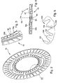
- FIG. 2 shows a disk which is used in the multi-disk clutch
- FIG. 3 shows a detail III from FIG. 2 .
- FIG. 4 shows a view of the toothed inner edge of the disk
- FIG. 5 shows a detail of an alternative configuration of the tooth system of the disk with reference to an internally toothed disk
- FIG. 6 shows a further exemplary configuration of an all-wheel drive train with a central differential lock which has a Bonanza effect element.
- FIG. 1 shows part of a longitudinally installed all-wheel drive train for a motor vehicle.
- the all-wheel drive train has a transmission output shaft 2 pointing toward the rear of the motor vehicle in the installed state.
- This transmission output shaft 2 forms the input shaft 6 of the central differential 3 .
- the automatic transmission 1 has a transmission housing 4 with an integrally formed bearing housing 5 for a lateral output 7 , so that the automatic transmission 1 can be used cost-effectively according to the “add-on principle” for an all-wheel drive vehicle.
- the transmission output shaft 2 or input shaft 6 for the lateral output 7 is connected via the central differential 3 and a rear-drive cardan shaft to a pinion shaft of a rear-axle transmission (not shown) in such a way that a first portion of the drive torque is transmitted to the rear-axle transmission.
- a second portion of the drive torque is transmitted to a front axle by the input shaft 6 via
- the cardan shaft 10 of the lateral output 7 is swivelled horizontally by an angle of about 8° relative to the drive-train longitudinal axis 11 .
- the cardan shaft 10 of the lateral output 7 is swivelled vertically by an angle of about 4° relative to the drive-train longitudinal axis 11 .
- the lateral output 7 is formed by two gears, to be precise by the drive pinion 8 and the output pinion 9 meshing with the latter.
- the drive pinion 8 is connected in a rotationally fixed manner to a hollow shaft 12 which is designed in one piece with a sun gear of the central differential 3 .
- the transmission output shaft 2 and the input shaft 6 extend inside this hollow shaft 12 .
- the output pinion 9 is in principle a hollow, externally toothed shaft which is mounted by means of a set of tapered roller bearings in an x arrangement, that is, centrally in the bearing housing 5 .
- the cardan shaft 10 is arranged in an articulated manner radially inside the output pinion 9 by means of a universal joint. Furthermore, in the direction of travel at the front, i.e. at its other end, the cardan shaft 10 is coupled in an articulated manner by means of a further universal joint to the bevel pinion shaft of the front-axle transmission.
- the drive pinion 8 and the output pinion 9 meshing with it are each designed as a straight bevel gear.
- the cardan shaft 10 is arranged on the right side of the driving engine (not shown) in the direction of vehicle travel.
- the all-wheel drive train has a controllable differential lock 13 for the central differential 3 , this differential lock 13 being additionally designed as a Bonanza effect element or limited slip clutch.
- the differential lock 13 is arranged directly adjacent to the automatic transmission 1 between the latter and the drive pinion 8 .
- the differential lock 13 comprises a multi-disk clutch 14 , by means of which
- the two clutch halves 15 , 16 can be pressed axially against one another by means of an annular regulating piston 17 .
- the control piston 17 is supported axially on one side on the transmission housing 4 and on the other side via an axial rolling-contact bearing on a disk 18 of the first clutch half 15 .
- This disk 18 Axially following this disk 18 in an alternating manner in the direction pointing forward are the other disks of the two clutch halves 15 , 16 , an abutment disk 20 adjoining the last disk 19 of the second clutch half 16 , this abutment disk 20 bearing axially against a support pot 21 , which is connected to the transmission output shaft 2 in a rotationally fixed manner by means of a splined-shaft tooth system.
- This support pot is a rotary body 21 which is supported in the direction pointing axially forward on a step of the transmission output shaft 2 , so that all the disks of the differential lock 13 are restrained in the force flow between the transmission housing 4 and the transmission output shaft 2 when the control piston 17 is disengaged.
- the support pot 21 has an internal tooth system 94 for the rotationally fixed and axially displaceable connection to the disks of the second clutch half 16 .
- the disks of the second clutch half 16 at their outer edge region, have an external tooth system which engages in the internal tooth system of the support pot 21 .
- the internal tooth system of the support pot 21 is designed as a helical tooth system.
- the teeth of the external tooth system of the disks of the second coupling half 16 are in planar contact with this helical tooth system. To this end, the teeth of these disks are twisted by an angle of 77.7° about their tooth center axis like those of the disk which can be seen from FIG. 4 .
- the disks of the first clutch half 15 have an internal tooth system which transmits the torque in a positive-locking manner to an externally helically toothed socket 22 which is arranged on the front end of the hollow shaft 12 in a rotationally fixed manner by means of a splined-shaft tooth system.
- the socket 22 forms a rotary body and is supported on the one side at the front end of the transmission output shaft 2 on an axial locking ring. On the other side, the socket 22 is supported on a bearing inner ring of the tapered roller bearing which carries the drive pinion 8 .
- the external tooth system of the socket 22 is designed as a helical tooth system.
- the teeth of the internal tooth system of the disks of the first clutch half 15 are in planar contact with this helical tooth system. To this end, the teeth are designed in such a way as can be seen from FIGS. 2 to 4 .
- FIG. 2 shows the one disk 19 as an example of the disks of the first clutch half 15 , which are designed identically to one another.
- the annular friction surface Provided radially along the circumference of the disk 19 is the annular friction surface on both sides, which has oil-guide grooves.
- the disk In a radially central region, the disk has circumferentially curved elongated holes.
- the internal tooth system is arranged on the inner edge region, the teeth being twisted as shown in FIG. 3 .
- FIG. 3 shows a detail of the disk.
- FIG. 4 shows a view of the teeth of the internal tooth system from the drive-train longitudinal axis 11 or the rotation axis 99 congruent with the latter.
- the tooth flanks 30 a , 30 b are in planar contact with the tooth flanks of the externally helically toothed socket 22 . Consequently, the helical tooth system of the socket 22 has an angle corresponding to ⁇ , so that the tooth flanks 30 a , 30 b of the teeth of the disk 19 extend parallel to the tooth flanks of the helical tooth system of the socket 22 .
- the disks of the second clutch half 16 are correspondingly adapted and designed in a similar manner to the first clutch half. An important difference is merely that the teeth lie on the outer edge of the disk. In particular, the twisting of the teeth of the external tooth system of the disks of the second clutch half corresponds to the twisting of the internal tooth system of the disk 19 .
- FIG. 5 shows a detail of an alternative configuration of the tooth system of the disk with reference to an internally toothed disk 100 .
- a rounded recess 104 is provided in the tooth root between each two teeth 101 .
- each of the teeth is twisted by said 77.7° about the tooth center axis 198 down to a step 102 , from which the recess 104 extends.
- the angle of twist then decreases continuously from this point, so that there is no longer any twist in the root 103 of the recess 104 . That is to say the surface of the radially outer annular region of the disk 100 lies perpendicularly or at 90° to the rotation axis.
- the multi-disk clutch of the exemplary embodiment according to FIG. 1 is additionally designed as a Bonanza effect element.
- a Bonanza effect element dampens Bonanza effects during pull-push changes and push-pull changes, as is already described in DE 101 11 257.2.
- the slip torque of the Bonanza effect element is also freely selectable.
- the slip torque can be set according to whether the vehicle driver has depressed a button “off-road” or “winter”.
- the slip torque can be set as a function of the vehicle speed, the current transmission ratio or according to whether the vehicle senses a roadway wetted by rain. In particular, an infinitely variable setting of the slip torque is possible.
- FIG. 6 in a further exemplary configuration, shows an all-wheel drive train having a central differential 203 which has a Bonanza effect element 213 .
- a central differential lock is not provided in this exemplary configuration, although such a central differential lock could be provided in the same region as the Bonanza effect element 213 or alternatively in accordance with the installation according to FIG. 1 .
- components which are of essentially the same construction as the first exemplary configuration according to FIG. 1 are not explained in more detail.
- a sun gear 250 of the central differential 203 assumes three functions. The sun gear 250
- the inner disks 218 are pre-stressed axially against outer disks 219 by means of a pre-stressed Belleville spring 299 .
- the inner disks 218 are rotationally fixed and axially displaceable relative to the sun gear 250
- the outer disks 219 are rotationally fixed and axially displaceable relative to the planet carrier 252 of the central differential 203 .
- an external tooth system of the outer disks 219 engages in an internal tooth system of the planet carrier 252 .
- This connection may be designed both as a spur tooth system and alternatively as a helical tooth system, the teeth of the outer disks 219 in the latter case being in planar contact with the helical internal tooth system of the planet carrier 252 .
- Said pre-stressed Belleville spring 299 may also be designed according to EP 1 238 847 A2, so that a slip torque of the Bonanza effect element is temperature-dependent.
- the inner disks 218 may be designed with recesses according to FIG. 5 .
- the transmission may be any desired transmission.
- it may be:
- the disk according to the invention is not restricted to central differentials.
- the disks are also suitable, inter alia, for use in differential locks of a transverse differential of the rear axle and/or of the front axle.
- the disk according to the invention is also suitable for multi-disk clutches/brakes of automatic transmissions, such as, for example, epicyclic automatic transmissions or twin-clutch transmissions.
- the disk according to the invention may likewise be used in an epicyclic reversing set for the reverse gear, for example of an infinitely variable transmission.
- the multi-disk clutch may also be designed as a Bonanza effect element for damping torque shock effects as a function of temperature, as is described in DE 101 11 257.2, which is not pre-published.
- the cardan shaft may also be a lateral shaft without joints.
- the rotary body need not necessarily be rotationally symmetrical, but rather may have any other desired forms, since, in a clutch, only the relative rotation between two clutch halves is necessary for the functioning.
- one of the two clutch halves is a stationary component, such as, for example, a brake component fixed to a housing, a rotationally symmetrical form is not necessary.
- the disk or the multi-disk clutch is not restricted to the intended use in motor vehicles. Use in other sectors, in particular in machine construction, is also conceivable. For example, use in transmissions or slip clutches of machine tools or production machinery is conceivable.
Landscapes
- Engineering & Computer Science (AREA)
- General Engineering & Computer Science (AREA)
- Mechanical Engineering (AREA)
- Retarders (AREA)
- Mechanical Operated Clutches (AREA)
Applications Claiming Priority (3)
| Application Number | Priority Date | Filing Date | Title |
|---|---|---|---|
| DE10333946.9 | 2003-07-25 | ||
| DE10333946A DE10333946B4 (de) | 2003-07-25 | 2003-07-25 | Lamelle für eine Lamellenkupplung |
| PCT/EP2004/008001 WO2005012750A1 (de) | 2003-07-25 | 2004-07-17 | Lamelle für eine lamellenkupplung und herstellungsverfahren |
Related Parent Applications (1)
| Application Number | Title | Priority Date | Filing Date |
|---|---|---|---|
| PCT/EP2004/008001 Continuation-In-Part WO2005012750A1 (de) | 2003-07-25 | 2004-07-17 | Lamelle für eine lamellenkupplung und herstellungsverfahren |
Publications (2)
| Publication Number | Publication Date |
|---|---|
| US20060151275A1 US20060151275A1 (en) | 2006-07-13 |
| US7399249B2 true US7399249B2 (en) | 2008-07-15 |
Family
ID=34111668
Family Applications (1)
| Application Number | Title | Priority Date | Filing Date |
|---|---|---|---|
| US11/337,229 Expired - Fee Related US7399249B2 (en) | 2003-07-25 | 2006-01-20 | Disk for a multi-disk clutch and production method thereof |
Country Status (4)
| Country | Link |
|---|---|
| US (1) | US7399249B2 (ja) |
| JP (1) | JP4833063B2 (ja) |
| DE (1) | DE10333946B4 (ja) |
| WO (1) | WO2005012750A1 (ja) |
Cited By (1)
| Publication number | Priority date | Publication date | Assignee | Title |
|---|---|---|---|---|
| US20140148297A1 (en) * | 2012-11-29 | 2014-05-29 | Os Giken Co., Ltd. | Differential device with limited-slip differential mechanism |
Families Citing this family (7)
| Publication number | Priority date | Publication date | Assignee | Title |
|---|---|---|---|---|
| DE102007038150B4 (de) | 2007-08-13 | 2010-04-29 | Magna Powertrain Ag & Co Kg | Steuerverfahren für Kupplungsanordnung |
| DE102008013910A1 (de) * | 2008-03-12 | 2009-09-17 | Volkswagen Ag | Nasslaufende Lamellenkupplung |
| DE102010061751A1 (de) * | 2010-11-23 | 2012-05-24 | Zf Friedrichshafen Ag | Anordnung zur Lagerung von kegeligen Stirnrädern |
| AT513583A1 (de) * | 2012-11-06 | 2014-05-15 | Miba Frictec Gmbh | Kupplungslamelle |
| DE102014201867A1 (de) | 2013-02-22 | 2014-08-28 | Magna Powertrain Ag & Co. Kg | Kupplungsscheibe |
| DE102019127238A1 (de) * | 2019-04-10 | 2020-10-15 | Schaeffler Technologies AG & Co. KG | Lamellenkupplung, insbesondere für einen Hybrid-Antriebsstrang |
| DE102019008231B4 (de) * | 2019-11-27 | 2026-02-12 | Mercedes-Benz Group AG | Stahllamelle für ein Reibschaltelement eines Kraftfahrzeugantriebsstrangs |
Citations (15)
| Publication number | Priority date | Publication date | Assignee | Title |
|---|---|---|---|---|
| US1415841A (en) | 1920-09-24 | 1922-05-09 | Charles G Seitz | Disk clutch |
| FR1492280A (fr) | 1966-07-07 | 1967-08-18 | Ferodo Sa | Perfectionnements aux frictions d'embrayage à moyeu amortisseur |
| DE1450784A1 (de) | 1964-05-27 | 1970-01-29 | Anton Ottenschlaeger | Kupplung mit Wendetriebsatz |
| US3721794A (en) | 1970-12-22 | 1973-03-20 | Toyota Motor Co Ltd | Clutch device |
| DE2459031A1 (de) | 1974-12-13 | 1976-06-16 | Zahnradfabrik Friedrichshafen | Kupplungslamellen mit radialer verzahnung |
| US4140030A (en) * | 1976-07-26 | 1979-02-20 | Rockwell International Corporation | Power transmission |
| DE3236613A1 (de) | 1982-10-02 | 1984-04-05 | Adam Opel AG, 6090 Rüsselsheim | Einscheiben-reibungskupplung fuer kraftfahrzeuge |
| US4446955A (en) | 1980-07-03 | 1984-05-08 | Borg-Warner Corporation | Clutch driven plate assembly with a floating hub |
| US4450943A (en) | 1982-01-21 | 1984-05-29 | Dana Corporation | Helical spline clutch plate separator |
| DE3601903A1 (de) | 1985-02-09 | 1986-08-14 | LuK Lamellen und Kupplungsbau GmbH, 7580 Bühl | Bauelement, insbesondere fuer kupplungsscheiben fuer kraftfahrzeuge |
| US4890510A (en) * | 1987-02-20 | 1990-01-02 | Toyota Jidosha Kabushiki Kaisha | Center differential for four-wheel drive vehicle |
| US5916054A (en) * | 1996-07-30 | 1999-06-29 | Fuji Jukogyo Kabushiki Kaisha | Driving force distributing apparatus for four wheel drive vehicle |
| EP1058018A2 (en) | 1999-05-18 | 2000-12-06 | ADLER S.p.A. | Plate-type clutch with helical means for dynamically adjusting the axial compression load on the plates |
| EP1238847A2 (de) | 2001-03-09 | 2002-09-11 | DaimlerChrysler AG | Kraftfahrzeug-Antriebsstrang |
| EP1273473A2 (de) | 2001-07-07 | 2003-01-08 | DaimlerChrysler AG | Getriebevorrichtung |
Family Cites Families (6)
| Publication number | Priority date | Publication date | Assignee | Title |
|---|---|---|---|---|
| JPS5747028A (en) * | 1980-07-03 | 1982-03-17 | Borg Warner | Driven plate assembly of clutch with floating hub |
| JPS61123226A (ja) * | 1984-11-20 | 1986-06-11 | Mitsubishi Electric Corp | 伝送系デ−タの監視方法 |
| JPH034827Y2 (ja) * | 1985-01-21 | 1991-02-07 | ||
| JPH0266320A (ja) * | 1988-08-31 | 1990-03-06 | Moriyama Kogyo Kk | ヘリカルスプライン構造 |
| JPH03265718A (ja) * | 1990-03-12 | 1991-11-26 | Nissan Motor Co Ltd | 湿式多板クラッチ |
| JP3844532B2 (ja) * | 1995-11-20 | 2006-11-15 | Gkn ドライブライン トルクテクノロジー株式会社 | デファレンシャル装置 |
-
2003
- 2003-07-25 DE DE10333946A patent/DE10333946B4/de not_active Expired - Fee Related
-
2004
- 2004-07-17 JP JP2006520757A patent/JP4833063B2/ja not_active Expired - Fee Related
- 2004-07-17 WO PCT/EP2004/008001 patent/WO2005012750A1/de not_active Ceased
-
2006
- 2006-01-20 US US11/337,229 patent/US7399249B2/en not_active Expired - Fee Related
Patent Citations (15)
| Publication number | Priority date | Publication date | Assignee | Title |
|---|---|---|---|---|
| US1415841A (en) | 1920-09-24 | 1922-05-09 | Charles G Seitz | Disk clutch |
| DE1450784A1 (de) | 1964-05-27 | 1970-01-29 | Anton Ottenschlaeger | Kupplung mit Wendetriebsatz |
| FR1492280A (fr) | 1966-07-07 | 1967-08-18 | Ferodo Sa | Perfectionnements aux frictions d'embrayage à moyeu amortisseur |
| US3721794A (en) | 1970-12-22 | 1973-03-20 | Toyota Motor Co Ltd | Clutch device |
| DE2459031A1 (de) | 1974-12-13 | 1976-06-16 | Zahnradfabrik Friedrichshafen | Kupplungslamellen mit radialer verzahnung |
| US4140030A (en) * | 1976-07-26 | 1979-02-20 | Rockwell International Corporation | Power transmission |
| US4446955A (en) | 1980-07-03 | 1984-05-08 | Borg-Warner Corporation | Clutch driven plate assembly with a floating hub |
| US4450943A (en) | 1982-01-21 | 1984-05-29 | Dana Corporation | Helical spline clutch plate separator |
| DE3236613A1 (de) | 1982-10-02 | 1984-04-05 | Adam Opel AG, 6090 Rüsselsheim | Einscheiben-reibungskupplung fuer kraftfahrzeuge |
| DE3601903A1 (de) | 1985-02-09 | 1986-08-14 | LuK Lamellen und Kupplungsbau GmbH, 7580 Bühl | Bauelement, insbesondere fuer kupplungsscheiben fuer kraftfahrzeuge |
| US4890510A (en) * | 1987-02-20 | 1990-01-02 | Toyota Jidosha Kabushiki Kaisha | Center differential for four-wheel drive vehicle |
| US5916054A (en) * | 1996-07-30 | 1999-06-29 | Fuji Jukogyo Kabushiki Kaisha | Driving force distributing apparatus for four wheel drive vehicle |
| EP1058018A2 (en) | 1999-05-18 | 2000-12-06 | ADLER S.p.A. | Plate-type clutch with helical means for dynamically adjusting the axial compression load on the plates |
| EP1238847A2 (de) | 2001-03-09 | 2002-09-11 | DaimlerChrysler AG | Kraftfahrzeug-Antriebsstrang |
| EP1273473A2 (de) | 2001-07-07 | 2003-01-08 | DaimlerChrysler AG | Getriebevorrichtung |
Cited By (2)
| Publication number | Priority date | Publication date | Assignee | Title |
|---|---|---|---|---|
| US20140148297A1 (en) * | 2012-11-29 | 2014-05-29 | Os Giken Co., Ltd. | Differential device with limited-slip differential mechanism |
| US9062750B2 (en) * | 2012-11-29 | 2015-06-23 | Os Giken Co., Ltd. | Differential gears with a mechanism for controlling differential motion |
Also Published As
| Publication number | Publication date |
|---|---|
| JP2007533913A (ja) | 2007-11-22 |
| WO2005012750A1 (de) | 2005-02-10 |
| DE10333946A1 (de) | 2005-03-03 |
| JP4833063B2 (ja) | 2011-12-07 |
| DE10333946B4 (de) | 2010-01-14 |
| US20060151275A1 (en) | 2006-07-13 |
Similar Documents
| Publication | Publication Date | Title |
|---|---|---|
| US7383748B2 (en) | Automotive drivetrain having deflection compensation | |
| US6705966B2 (en) | Motor-vehicle drive train | |
| US7905312B2 (en) | Driving force transmitting device for four-wheel drive vehicle | |
| US7749123B2 (en) | Cycloid limited slip differential and method | |
| US4513633A (en) | Positive drive and generated cam surfaces therefor | |
| EP0239763B1 (en) | Single shaft positive drive | |
| US11156252B2 (en) | Boot assembly for a constant velocity joint | |
| US7399249B2 (en) | Disk for a multi-disk clutch and production method thereof | |
| US4594913A (en) | Double-acting differential with slip limiting elements | |
| US10479198B2 (en) | Transfer case with active clutch on front output and pass-thru rear output | |
| US7390278B2 (en) | Torque-coupling device for front-wheel-drive transaxle unit | |
| US5524738A (en) | Jaw clutch having profiled jaw clutch elements | |
| US7083541B2 (en) | Axle drive block with a differential lock | |
| US20220136569A1 (en) | Torque transmission device for a motor vehicle | |
| JPS6333590B2 (ja) | ||
| US4643284A (en) | Non-differential drive axle | |
| US8961349B2 (en) | Differential with tailored torque bias ratios | |
| CN105240484A (zh) | 电控多片式自锁驱动桥 | |
| US20090205921A1 (en) | Torque Limiting Shaft Flange Assembly | |
| US8267235B2 (en) | Torque limiting clutch assembly | |
| GB2182733A (en) | Limited slip differential gears for motor vehicles | |
| Kumar et al. | Transmission of SAE Baja | |
| US4983150A (en) | Differential gear apparatus with differential limitation mechanism | |
| US20160121720A1 (en) | Multi-speed transfer case | |
| JPH08145145A (ja) | 差動制限装置 |
Legal Events
| Date | Code | Title | Description |
|---|---|---|---|
| AS | Assignment |
Owner name: DAIMLERCHRYSLER AG, GERMANY Free format text: ASSIGNMENT OF ASSIGNORS INTEREST;ASSIGNORS:GANSLOSER, PHILIP;HAERTER, TOBIAS;KLEIN, WERNER;AND OTHERS;REEL/FRAME:017702/0195 Effective date: 20060202 |
|
| FEPP | Fee payment procedure |
Free format text: PAYOR NUMBER ASSIGNED (ORIGINAL EVENT CODE: ASPN); ENTITY STATUS OF PATENT OWNER: LARGE ENTITY |
|
| AS | Assignment |
Owner name: DAIMLER AG, GERMANY Free format text: CHANGE OF NAME;ASSIGNOR:DAIMLERCHRYSLER AG;REEL/FRAME:021053/0237 Effective date: 20071019 |
|
| FPAY | Fee payment |
Year of fee payment: 4 |
|
| REMI | Maintenance fee reminder mailed | ||
| LAPS | Lapse for failure to pay maintenance fees | ||
| STCH | Information on status: patent discontinuation |
Free format text: PATENT EXPIRED DUE TO NONPAYMENT OF MAINTENANCE FEES UNDER 37 CFR 1.362 |
|
| STCH | Information on status: patent discontinuation |
Free format text: PATENT EXPIRED DUE TO NONPAYMENT OF MAINTENANCE FEES UNDER 37 CFR 1.362 |
|
| FP | Lapsed due to failure to pay maintenance fee |
Effective date: 20160715 |