US7285204B2 - Apparatus for detecting deterioration of air-fuel ratio sensor - Google Patents
Apparatus for detecting deterioration of air-fuel ratio sensor Download PDFInfo
- Publication number
- US7285204B2 US7285204B2 US10/633,540 US63354003A US7285204B2 US 7285204 B2 US7285204 B2 US 7285204B2 US 63354003 A US63354003 A US 63354003A US 7285204 B2 US7285204 B2 US 7285204B2
- Authority
- US
- United States
- Prior art keywords
- air
- fuel ratio
- ratio sensor
- detecting
- temperature
- Prior art date
- Legal status (The legal status is an assumption and is not a legal conclusion. Google has not performed a legal analysis and makes no representation as to the accuracy of the status listed.)
- Expired - Fee Related, expires
Links
Images


Classifications
-
- F—MECHANICAL ENGINEERING; LIGHTING; HEATING; WEAPONS; BLASTING
- F02—COMBUSTION ENGINES; HOT-GAS OR COMBUSTION-PRODUCT ENGINE PLANTS
- F02D—CONTROLLING COMBUSTION ENGINES
- F02D41/00—Electrical control of supply of combustible mixture or its constituents
- F02D41/02—Circuit arrangements for generating control signals
- F02D41/14—Introducing closed-loop corrections
- F02D41/1438—Introducing closed-loop corrections using means for determining characteristics of the combustion gases; Sensors therefor
- F02D41/1493—Details
- F02D41/1495—Detection of abnormalities in the air/fuel ratio feedback system
-
- F—MECHANICAL ENGINEERING; LIGHTING; HEATING; WEAPONS; BLASTING
- F02—COMBUSTION ENGINES; HOT-GAS OR COMBUSTION-PRODUCT ENGINE PLANTS
- F02D—CONTROLLING COMBUSTION ENGINES
- F02D41/00—Electrical control of supply of combustible mixture or its constituents
- F02D41/02—Circuit arrangements for generating control signals
- F02D41/021—Introducing corrections for particular conditions exterior to the engine
- F02D41/0235—Introducing corrections for particular conditions exterior to the engine in relation with the state of the exhaust gas treating apparatus
-
- F—MECHANICAL ENGINEERING; LIGHTING; HEATING; WEAPONS; BLASTING
- F02—COMBUSTION ENGINES; HOT-GAS OR COMBUSTION-PRODUCT ENGINE PLANTS
- F02D—CONTROLLING COMBUSTION ENGINES
- F02D41/00—Electrical control of supply of combustible mixture or its constituents
- F02D41/02—Circuit arrangements for generating control signals
- F02D41/14—Introducing closed-loop corrections
- F02D41/1438—Introducing closed-loop corrections using means for determining characteristics of the combustion gases; Sensors therefor
- F02D41/1444—Introducing closed-loop corrections using means for determining characteristics of the combustion gases; Sensors therefor characterised by the characteristics of the combustion gases
- F02D41/1454—Introducing closed-loop corrections using means for determining characteristics of the combustion gases; Sensors therefor characterised by the characteristics of the combustion gases the characteristics being an oxygen content or concentration or the air-fuel ratio
- F02D41/1456—Introducing closed-loop corrections using means for determining characteristics of the combustion gases; Sensors therefor characterised by the characteristics of the combustion gases the characteristics being an oxygen content or concentration or the air-fuel ratio with sensor output signal being linear or quasi-linear with the concentration of oxygen
-
- F—MECHANICAL ENGINEERING; LIGHTING; HEATING; WEAPONS; BLASTING
- F02—COMBUSTION ENGINES; HOT-GAS OR COMBUSTION-PRODUCT ENGINE PLANTS
- F02D—CONTROLLING COMBUSTION ENGINES
- F02D41/00—Electrical control of supply of combustible mixture or its constituents
- F02D41/02—Circuit arrangements for generating control signals
- F02D41/14—Introducing closed-loop corrections
- F02D41/1438—Introducing closed-loop corrections using means for determining characteristics of the combustion gases; Sensors therefor
- F02D41/1493—Details
- F02D41/1494—Control of sensor heater
Definitions
- the present invention relates to an air-fuel ratio sensor, particularly to a deterioration detecting apparatus for an air-fuel ratio sensor for diagnosing a deterioration of a downstream air-fuel ratio sensor arranged downstream from a catalyst. More specifically, the present invention relates to an apparatus for detecting a deterioration of an air-fuel ratio sensor capable of detecting a deterioration of a downstream air-fuel ratio sensor at early time and accurately.
- a deterioration of the catalyst is diagnosed by comparing outputs of the two oxygen sensors provided upstream and downstream from the catalyst. Therefore, when the respective oxygen sensors are deteriorated, accuracy of diagnosing the deterioration of the catalyst using the oxygen sensors is also deteriorated. Therefore it is necessary to detect the deterioration of the air-fuel ratio sensors.
- the upstream oxygen sensor is arranged upstream from the catalyst, an oxygen concentration in exhaust emission gas emitted from the engine is directly detected. Therefore, when a variation of the air-fuel ratio is brought about, the upstream oxygen sensor immediately reacts with the variation of the air-fuel ratio. Hence, the deterioration of the upstream oxygen sensor can comparatively easily be detected by monitoring the output of the upstream air-fuel ratio sensor when the variation of the air-fuel ratio is brought about.
- the downstream oxygen sensor since the downstream oxygen sensor is provided downstream from the catalyst, the downstream oxygen sensor detects the air-fuel ratio in emission gas after passing the catalyst. Therefore, even when the variation of the air-fuel ratio is brought about, the variation of the air-fuel ratio is smoothed by oxygen adsorption and separation by oxidation and reduction reaction of the catalyst or a storage effect of the catalyst and the downstream oxygen sensor detects the smoothed air-fuel ratio. Further, the storage effect of the catalyst is changed by the deterioration. Therefore, it is difficult to detect the deterioration of the downstream oxygen sensor per se from a state of reaction of the downstream oxygen sensor with respect to the variation of the air-fuel ratio of the engine.
- JP-U-03-037949 an output of an oxygen sensor downstream from a catalyst is detected with respect to a variation in an air-fuel ratio upstream from the catalyst before the catalyst is activated.
- JP-A-62-250351 deterioration is detected when an air-fuel ratio is changed more than a catalyst storage function as at fuel cut-off.
- a condition of detecting the deterioration is limited to that in cold starting.
- a condition of detecting the deterioration of the oxygen sensor at fuel cut-off as in JP-A-62-250351 is limited to that at fuel cut-off.
- fuel cut-off is hardly operated in running a city area. Therefore a frequency of executing deterioration detection is reduced.
- the executing condition is significantly limited. Therefore the frequency of detection is reduced. Further, even when the executing condition is established, the executing condition is under a transient condition. Therefore it is difficult to ensure detection accuracy.
- a deterioration of an air-fuel ratio sensor is detected by comparing outputs of the air-fuel ratio sensor when a temperature of a solid electrolyte element is adjusted at least to two different temperatures.
- Abnormality of the air-fuel ratio sensor is detected by utilizing a characteristic that when the temperature of the solid electrolyte element of the air-fuel ratio sensor is changed, sensitivity with respect to an emission gas component is changed by a difference in the temperature of the solid electrolyte element, that is, the activity of an electrode portion thereof.
- FIG. 1 is a schematic view of an engine system to which the present invention is applied;
- FIG. 2 is a flowchart of processing of setting a target air-fuel ratio according to a first embodiment of the present invention
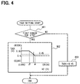
- FIG. 4 is a flowchart of processing of setting a target output voltage of a first oxygen sensor of the modification according to the first embodiment
- FIG. 6 is a map for setting a proportional amount of the first embodiment
- FIGS. 8A and 8B are time charts in detecting the impedance
- FIG. 10 is a flowchart of controlling a heater of the oxygen sensor of the first embodiment
- FIG. 11 is a block diagram of controlling an element temperature of the oxygen sensor
- FIG. 12 is a CO reaction characteristic diagram of the oxygen sensor
- FIG. 13 is an NO reaction characteristic diagram of the oxygen sensor
- FIG. 15 is a time chart showing operation in detecting the deterioration of the oxygen sensor
- FIG. 16 is a characteristic diagram showing principle of detecting the deterioration of the oxygen sensor
- FIG. 17 is a characteristic diagram showing an allowance of detecting the deterioration of the oxygen sensor
- FIG. 18 is a flowchart executed by ECU of a second embodiment of the present invention.
- FIG. 19 is a flowchart showing processing of detecting a deterioration of an oxygen sensor according to the second embodiment
- FIG. 20 is a flowchart executed by ECU of a modification of the second embodiment
- FIG. 21 is a time chart showing operation of the second embodiment
- FIG. 22 is a flowchart executed by ECU of a modification of the second embodiment
- FIG. 23 is a correlation diagram showing a relationship between a variation in an air-fuel ratio before a catalyst and a summed value of a variation in a sensor output;
- FIG. 24 is a flowchart executed by ECU of a modification of the second embodiment.
- FIG. 25 is a correlation diagram showing a relationship between an intake air amount and a sensor output variation.
- FIG. 1 an air-fuel ratio control system of a gasoline injection engine is shown.
- a fuel injection amount to the engine is controlled to a desired air-fuel ratio based on a detection result by air-fuel ratio sensors.
- an air cleaner 13 At the most upstream portion of an intake pipe 12 of an engine 11 , an air cleaner 13 is provided. On the downstream of the air cleaner 13 , an air flow meter 14 for detecting an intake air amount is provided. On the downstream of the air flow meter 14 , a throttle valve 15 and a throttle opening degree sensor 16 for detecting a throttle opening degree are provided.
- a surge tank 17 is provided on the downstream of the throttle valve 15 .
- an intake pipe pressure sensor 18 for detecting an intake pipe pressure is provided at the surge tank 17 .
- an intake manifold 19 for introducing air to respective cylinders of the engine 11 is provided at the surge tank 17 .
- a fuel injection valve 20 for injecting fuel is attached at the surge tank 17 .
- an upstream catalyst 22 and a downstream catalyst 23 for reducing harmful components (CO, HC, NOx or the like) in emission gas are installed in series.
- the upstream catalyst 22 is formed in a comparatively small capacity such that warming up is finished at early time in starting and exhaust emission in starting is reduced.
- the downstream catalyst 23 is formed in a comparatively large capacity such that emission gas can sufficiently be cleaned even in a high load region increasing an amount of emission gas.
- a linear air-fuel ratio sensor 24 for outputting a linear air-fuel ratio signal in accordance with an air-fuel ratio of emission gas is provided.
- a first oxygen sensor 25 and a second oxygen sensor 26 are provided on the downstream of the upstream catalyst 22 and on the downstream of the downstream catalyst 23 .
- Those sensors 25 and 26 have a so-called Z characteristic in which outputs thereof are respectively changed comparatively rapidly in the vicinity of a stoichiometric air-fuel ratio.
- a combination of the linear air-fuel ratio sensor and the oxygen sensors is described as an air-fuel ratio sensor.
- a cooling water temperature sensor 27 for detecting cooling water temperature
- a crank angle sensor 28 for detecting an engine rotational number NE are attached.
- ECU 29 is mainly constituted by a microcomputer and controls, for example, an air-fuel ratio of emission gas by a feedback control by executing a program stored in ROM (storage medium) included therein.
- the air-fuel ratio of emission gas is controlled by a known feedback control manner.
- FIG. 2 is a flowchart of an air-fuel ratio feedback control when the linear air-fuel ratio sensor 24 is used as an air-fuel ratio sensor on the upstream of the catalyst and either one of the first oxygen sensor 25 and the second oxygen sensor 26 is switched to use as an air-fuel ratio sensor on the downstream of the catalyst.
- FIG. 3 and FIG. 4 are flowcharts of other air-fuel ratio feedback control when the second oxygen sensor 26 is used in addition to the linear air-fuel ratio sensor 24 and the first oxygen sensor 25 of FIG. 1 .
- the oxygen sensor on the downstream used for setting a target air-fuel ratio ⁇ TG is selected form the first oxygen sensor 25 and the second oxygen sensor 26 .
- emission gas can considerably be cleaned only by the upstream catalyst 22 . Therefore, response of the air-fuel ratio control is excellent when the first oxygen sensor 25 is used as the sensor on the downstream used for setting the target air-fuel ratio ⁇ TG.
- the emission gas flow rate is increased, an emission gas component amount passing through the upstream catalyst 22 without being cleaned at inside thereof is increased. Therefore, it is necessary to clean emission gas by effectively using both of the upstream catalyst 22 and the downstream catalyst 23 .
- the second oxygen sensor 26 When either one of the two conditions ⁇ 1> and ⁇ 2> is satisfied, the second oxygen sensor 26 is selected and when both of the conditions are not satisfied, the first oxygen sensor 25 is selected. Further, the second oxygen sensor 26 may be selected when both of conditions ⁇ 1> and ⁇ 2> are satisfied.
- the processing proceeds to step 703 and determines whether the air-fuel ratio is lean also at preceding time.
- the processing proceeds to step 704 and calculates a rich integration amount ⁇ IR from a data map in accordance with a current intake air amount QA.
- maps of the rich integration amount ⁇ IR a map for the upstream catalyst downstream sensor (first oxygen sensor) is stored as shown in FIG. 5A , and a map for the downstream catalyst downstream sensor (second oxygen sensor) is stored as shown in FIG. 5B . Either one of the maps is selected in accordance with the sensor used.
- a map characteristic of the rich integration amount ⁇ IR is set such that the larger the intake air amount QA, the smaller the rich integration amount ⁇ IR.
- the rich integration amount ⁇ IR is set to be slightly larger in the map for the downstream catalyst downstream sensor than in the map for the upstream catalyst downstream sensor.
- step 703 when the air-fuel ratio has been rich at preceding time and is inverted to lean at current time, the processing proceeds from step 703 to step 706 and calculates a proportional (skip) amount ⁇ SKR to the rich side in accordance with the rich component storage amount OSTRich of the catalyst. Further, the rich component storage amount OSTRich is calculated in the manner known in the art.
- a map characteristic of FIG. 6 is set such that the smaller the absolute value of the rich component storage amount OSTRich, the smaller the rich skip amount ⁇ SKR.
- the processing proceeds to step 707 , corrects the target air-fuel ratio ⁇ TG to the rich side by ⁇ IR+ ⁇ SKR, stores rich or lean at that time (step 713 ) and finishes the program.
- step 702 when the output voltage VOX 2 of the oxygen sensor is rich, the processing proceeds to step 708 and determines whether the air-fuel ratio has been rich also at preceding time. When the air-fuel ratio is rich both at preceding time and current time, the processing proceeds to step 709 and calculates a lean integration amount ⁇ IL from the maps shown in FIGS. 5A and 5B in accordance with the current intake air amount QA.
- a map for the upstream catalyst downstream sensor first oxygen sensor
- a map for the downstream catalyst downstream sensor second oxygen sensor
- Either one of the maps is selected in accordance with a sensor selected as the sensor on the downstream.
- a map characteristic of the lean integration amount ⁇ IL of FIG. 5A and FIG. 5B is set such that the larger the intake air amount QA, the smaller the lean integration amount ⁇ IL and at a region where the intake air amount QA is small, the lean integration amount ⁇ IL is set to be slightly larger in the map for the downstream catalyst downstream sensor than in the map for the upstream catalyst downstream sensor.
- the processing proceeds to step 710 , corrects the target air-fuel ratio ⁇ TG to the lean side by ⁇ IL, stores rich or lean at that time (step 713 ) and finishes the program.
- step 708 calculates the skip amount ⁇ SKL to the lean side from the map shown in FIG. 6 in accordance with the lean component storage amount OSTLean of the catalyst. Further, processing of calculating the lean component storage amount OSTLean is performed in the known manner.
- the map characteristic of FIG. 6 is set such that the smaller the lean component storage amount OSTLean, the smaller the lean skip amount ⁇ SKL. Thereafter at step 712 , the operation corrects the target air-fuel ratio ⁇ TG by ⁇ IL+ ⁇ SKL, stores rich or lean at that time (step 713 ) and finishes the program.
- the rich skip amount ⁇ SKR or the lean skip amount ⁇ SKL is gradually set to a small value. Therefore, it can be prevented beforehand that the harmful component is emitted by carrying out excessive correction exceeding adsorption limits of the catalysts 22 and 23 .
- ECU 29 changes a target output voltage TGOX of the first oxygen sensor 25 in accordance with the output of the second oxygen sensor 26 when the first oxygen sensor 25 is selected as the sensor on the downstream used in setting the target air fuel ratio ⁇ TG of the air-fuel ratio feedback control by executing a target air-fuel ratio setting program of FIG. 3 and a target output voltage setting program of FIG. 4 .
- a difference from of FIG. 2 will mainly be explained.
- the sensor on the downstream used in setting the target air-fuel ratio ⁇ TG is selected from the oxygen sensor 25 on the downstream of the upstream catalyst 22 and the oxygen sensor 26 on the downstream of the downstream catalyst 23 , and thereafter the processing proceeds to step 714 and sets the target output voltage TGOX of the sensor 26 on the downstream used for setting the target air-fuel ratio ⁇ TG by executing a target output voltage setting program of FIG. 4 .
- step 715 determines rich or lean by whether the output voltage VOX 2 of the selected oxygen sensor is higher or lower than the target output voltage TGOX, calculates the target air-fuel ratio ⁇ TG by the above method at steps 703 through 713 in accordance with a result of the determination, stores rich or lean at that time and finishes the program.
- step 901 it is determined whether the first oxygen sensor 25 is selected as the sensor on the downstream used for setting the target air-fuel ratio ⁇ TG.
- the processing proceeds to step 902 and calculates the target output voltage TGOX in accordance with current output voltage V 2 of the second oxygen sensor 26 from a map of the target output voltage TGOX constituting a parameter by the output voltage of the second oxygen sensor 26 .
- the map of the target output voltage TGOX is set such that when the output voltage of the second oxygen sensor 26 (an air-fuel ratio of a gas flowing out from the downstream catalyst 23 ) falls in a predetermined range ( ⁇ output voltage ⁇ ) in the vicinity of the stoichiometric air-fuel ratio, the target output voltage TGOX is reduced (becomes lean) as the output of the second oxygen sensor 26 is increased (becomes rich). Further, in a region in which the output of the second oxygen sensor 26 is larger than a predetermined value ⁇ , the target output voltage TGOX becomes a predetermined lower limit value (for example, 0.4V). In a region in which the output of the second oxygen sensor 26 is smaller than a predetermined value ⁇ , the target output voltage TGOX becomes an upper limit value (for example, 0.65V).
- the target output voltage TGOX of the first oxygen sensor 25 is set to fall in a range in which an adsorption amount of an emission gas component of the downstream catalyst 23 becomes equal to or smaller than a predetermined value or the air-fuel ratio of emission gas flowing in the downstream catalyst 23 falls in a range of a predetermined cleaning window.
- step 901 when the second oxygen sensor 26 is selected as the sensor on the downstream used for setting the target air-fuel ratio ⁇ TG, the processing proceeds from step 901 to step 903 and sets the target output voltage TGOX to a predetermined value (for example, 0.45V).
- a predetermined value for example, 0.45V
- the linear air-fuel ratio sensor 24 is projected into the exhaust pipe 21 and the sensor 24 is constituted by a cover 132 , a sensor main body 131 and a heater 135 .
- the cover 134 is formed in a channel-like shape in a section thereof and a number of small holes communicating inside and outside of the cover 134 are formed at a peripheral wall thereof.
- the sensor main body 131 as the sensor element portion generates a voltage in correspondence with an oxygen concentration in an air-fuel ratio lean region, or a concentration of uncombusted gas (CO, HC, H 2 or the like) in an air-fuel ratio rich region.
- the heater 135 is contained at inside of an atmosphere side electrode layer 134 for heating the sensor main body (atmosphere side electrode layer, solid electrolyte layer, emission gas side electrode layer) by heat generating energy thereof.
- the heater 135 is provided with a heat generating capacity sufficient for activating the sensor main body 131 .
- ECU 29 is provided with a microcomputer (MC) 120 constituting the center of internal operation thereof.
- the microcomputer 120 is connected to a host microcomputer 116 for realizing fuel injection control or ignition control communicatably to each other.
- the linear air-fuel ratio sensor 24 is attached to the exhaust pipe 21 extended from an engine main body of the engine 11 and an output thereof is detected by the microcomputer 120 .
- the microcomputer 120 is constituted by well-known CPU, ROM, RAM, backup RAM and the like for executing various operation processing, not illustrated, for controlling a heater control circuit 125 and a bias control circuit 140 according to the prescribed controlling program.
- a bias instruction signal Vr is inputted to the bypass control circuit 140 via a D/A converter 121 , a low pass filter (LPF) 122 and a switch 160 . Further, the output of the linear air-fuel ratio sensor 24 in correspondence with the air-fuel ratio (oxygen concentration) from time to time is detected and a detected value thereof is inputted to the microcomputer 120 via an A/D converter 123 . Further, heater voltage and heater current are detected by the heater control circuit 125 , mentioned later, and a detected value thereof is inputted to the microcomputer 120 .
- LPF low pass filter
- the detected element impedance value is inputted to the microcomputer 120 .
- the element impedance is provided with a strong correlation with element temperature as shown by FIG. 9 and the element temperature of the air-fuel ratio sensor can be controlled by controlling a heater provided in the air-fuel ratio sensor by a duty control such that the element impedance becomes a predetermined value.
- element temperature of the oxygen sensor can be controlled by detecting element impedance and controlling a heater provided to each of the first and the second oxygen sensor 25 and 26 by a duty control such that the element impedance becomes a predetermined value.
- FIG. 10 there is adopted a method of carrying out PI control (proportional, integral) by a deviation between actually detected element impedance and target impedance calculated from the target element temperature, and the element temperature of the linear A/F sensor 24 (first oxygen sensor 25 , second oxygen sensor 26 ) is controlled by the method.
- PI control proportional, integral
- program processing is executed at predetermined timings (step 400 ).
- a deviation ( ⁇ imp) between the target impedance calculated from the target element temperature and the element impedance detected by the element impedance detecting circuit is calculated.
- an integrated value of the impedance deviation ( ⁇ imp) for carrying out integral control is calculated.
- the heater duty calculated here is inputted to the heater control circuit designated by numeral 125 of FIG. 7 and heater control of the linear air-fuel ratio sensor 24 (first oxygen sensor 25 , second oxygen sensor 26 ) is carried out.
- the heater duty is a control amount of a heat generating amount for controlling temperature of the oxygen sensor element and based on power (W).
- W power
- a correction relative to reference voltage for example, 13.5V
- a correction by power ⁇ (13.5/voltage) 2 is carried out.
- the ECU 29 is constructed and programmed as shown in FIG. 11 .
- the first oxygen sensor (oxygen sensor) 25 detects gas output by the emission gas component (rich gas and leans gas) emitted from the engine by an output detecting circuit 203 of ECU 29 and calculates an air-fuel ratio control amount by an air-fuel ratio (A/F) control calculating block 204 .
- A/F air-fuel ratio
- an amount of increasing or reducing the fuel injection amount is determined by comparing target voltage, not illustrated, and detected voltage.
- the fuel injection amount determined as the air-fuel ratio control amount is supplied to a fuel injector 20 and a desired fuel injection amount is injected.
- An impedance calculating block 202 calculates the element impedance as has been explained in reference to FIG. 7 and FIG.
- a heater control amount is determined by a deviation from the target impedance set by a target impedance setting block 213 by a heater control amount calculating block 214 .
- the heater is controlled such that the temperature of the sensor element of the first oxygen sensor 25 becomes desired temperature.
- a composition of emission gas emitted from the engine is mainly of rich gas or mainly of lean gas under a current operating condition or an operating state immediately thereafter.
- the target element temperature is set to, for example, 720° C. in order to elevate the element temperature of the oxygen sensor to promote lean gas reactivity.
- the target element temperature setting block 212 the target element temperature is set to, for example, 420° C. in order to lower the element temperature of the oxygen sensor to promote rich gas reactivity.
- a diagnosis execution determining block 215 it is determined whether an operating state in which deterioration detection (diagnosis) of the first oxygen sensor 25 or the second oxygen sensor 26 is to be executed is brought about based on a result of determining the operating state at the operating state determining block 210 .
- the element temperature of the oxygen sensor is controlled to a low temperature state (for example, 400° C.) for a predetermined period of time. Thereafter, the oxygen sensor element temperature is controlled to a high temperature state (for example, 700° C.) for a predetermined period of time.
- the target element temperature setting block 212 determines the target element temperature by putting priority on a determination result of the diagnosis execution determining block 215 more than a determination result of the specific gas sensitivity priority determining block. That is, when it is determined at the diagnosis execution determining block 215 that the operating state in which the diagnosis is to be executed is brought about, the target element temperature is set to the temperature for executing the diagnosis. Further, when it is determined at the diagnosis execution determining block 215 that the operating state in which the diagnosis is to be executed is not brought about, the target element temperature is set based on the result determined by the specific gas sensitivity priority determining block 211 .
- FIG. 12 shows a reactivity (electromotive force EMF) of an oxygen sensor with respect to carbon monoxide (CO) in nitrogen (N 2 ).
- EMF electroactive force
- FIG. 13 shows a reactivity (electromotive force EMF) of the oxygen sensor when nitrogen monoxide (NO) is introduced into an atmosphere of nitrogen (N 2 ) and carbon monoxide (CO).
- EMF electroactive force
- the target impedance is set from the relationship between the element impedance and the element temperature shown in FIG. 9 . Further, the heater control amount is determined by comparing with the above detected value of the element impedance at the heater control amount calculating block 214 .
- diagnosis processing of the first oxygen sensor 25 will be explained in reference to a flowchart of FIG. 14 . Further, although similar diagnosis processing is executed also with respect to the second oxygen sensor 26 , an explanation thereof will be omitted here.
- the routine is started at a predetermined timing of time or a number of times of injection (step 500 ).
- a condition of executing diagnosis is determined based on whether an engine rotational speed or an intake air amount falls in a predetermined range, or whether catalyst temperature is equal to or lower than predetermined temperature.
- the condition of executing diagnosis is a stable steady-state running state in order to promote accuracy of deterioration detection.
- low element temperature control is started by setting a target element impedance to 2000 ⁇ such that element temperature of the first oxygen sensor 25 becomes low (for example, 400° C.).
- step 503 it is determined whether the element impedance (imp) falls in a predetermined range in order to detect whether the element temperature is desired temperature.
- processing at step 502 and at step 503 are repeated until the impedance falls in the predetermined range.
- the processing proceeds to step 504 .
- an output voltage change speed of the first oxygen sensor 25 is calculated by calculating a change amount ⁇ V between predetermined timings of the output voltage of the first oxygen sensor 25 in the low element temperature state.
- ⁇ V
- notation Vn designates a current value of the first oxygen sensor 25 and notation Vn ⁇ 1 is a preceding value of the output of the first oxygen sensor 25 .
- the change speed is calculated without differentiating a rich direction of the oxygen sensor (change speed is a positive value) and a lean direction thereof (change speed is a negative value)
- the change speed may be calculated only in a specific direction of rich or lean.
- a change speed integrated value (sd1oxs1) is calculated based on the following equation by summing up the change speed for a predetermined time period.
- sd 1 oxs 1 ⁇ Vn ⁇ 1 + ⁇ Vn
- notation ⁇ Vn designates a current value of the change amount ⁇ V and the notation ⁇ Vn ⁇ 1 designates a preceding value of the change amount ⁇ V.
- step 506 it is determined whether a predetermined time period T 3 has elapsed.
- processing of step 504 to step 506 are repeated until it is determined that the predetermined time period T 3 elapses.
- the processing proceeds to step 507 .
- the element temperature control is switched to high element temperature control.
- the target impedance is set to 25 ⁇ such that the element is at high temperature (for example, 700° C.).
- step 508 it is determined whether the element impedance (imp) falls in a predetermined range (15 ⁇ imp ⁇ 25 ⁇ ).
- processing at step 507 and at step 508 is repeated until it is determined that the element impedance falls in the predetermined range.
- ) is calculated and at step 510 , the oxygen sensor voltage change speed integrated value sd1oxsh ( ⁇ Vn ⁇ 1+ ⁇ V) is calculated.
- step 511 it is determined whether a predetermined time period T 5 has elapsed at step 511 .
- processing of from step 509 to step 511 are repeated until the predetermined time period elapses.
- the processing proceeds to step 512 .
- step 513 the change speed integrated value deviation amount de1xh1 and a previously set predetermined value are compared.
- the processing proceeds to step 514 and determines that the first oxygen sensor is deteriorated.
- the processing proceeds to step 515 and determines that the first oxygen sensor is normal and not deteriorated.
- (a) shows whether the condition of executing the diagnosis processing is established. Further, (b) shows whether the element temperature control is requested at normal control time when the diagnosis processing are not executed, or low element temperature control time or high element temperature control time when the diagnosis processing are executed. Further, (c) shows the element temperature of the solid electrolyte. (d) shows the output of the first oxygen sensor when the sensor is deteriorated and (e) shows the output of the first oxygen sensor when the sensor is normal. (f) shows the change speed integrated value sd1oxs1 at low element temperature control time and (g) shows the change speed integrated value sd1oxsh at high element temperature control time. (h) shows the change speed integrated value deviation amount de1xh1. Further, (i) shows an abnormality detection flag.
- low element temperature control (low temperature control) of the element temperature of the first oxygen sensor is requested and the target impedance, not illustrated, is set to be large (for example, 2000 ⁇ ).
- the heater is controlled such that the element temperature of the solid electrolyte becomes 400° C.
- the output of the voltage of the normal oxygen sensor is varied by a large amount since the reactivity by rich gas (CO) is increased.
- the variation amount of the output of the deteriorated oxygen sensor is small since the reactivity is reduced.
- the change speed is calculated by calculating the output variation amount of the oxygen sensor at that time at every predetermined timing. The change speed calculated in this way is summed up until reaching time t 13 and the integrated value of the change speed sd1oxs1 at low temperature control is calculated.
- the high element temperature control (high temperature control) of the element temperature of the first oxygen sensor is requested and the target impedance is set to be small (for example, 25 ⁇ ).
- the heater is controlled such that the element temperature of the solid electrolyte becomes 700° C.
- the variation amount of the output voltage of the normal oxygen sensor is reduced since the reactivity by rich gas (CO) is reduced in comparison with that at low temperature control. Further, the variation amount of the deteriorated sensor is similarly reduced.
- the change speed integrated value sd1oxsh in high temperature control is calculated similar to that in low temperature control.
- the change speed integrated value deviation amount de1xh1 which is the deviation between the change speed integrated value sd1oxs1 at low temperature control time and the change speed integrated value sd1oxsh at high temperature control time is calculated.
- the deviation amount de1xh1 becomes a large value when the oxygen sensor is normal and becomes a small value when the oxygen sensor is deteriorated. Therefore, presence or absence of the deterioration can be determined by comparing with a predetermined determinant. Further, although according to the embodiment, it is determined whether the oxygen sensor is deteriorated or normal, a degree of the deterioration can also be detected by providing a plurality of determinants. Naturally, the deviation amount de1xh1 can also be used as an index of the degree of deterioration as it is.
- deterioration detection of the first oxygen sensor 25 is described, the embodiment is not limited thereto but can also be used for deterioration detection of the second oxygen sensor 26 . Further, the embodiment can also be used for the linear air-fuel ratio sensor 24 .
- the diagnosis processing according to the embodiment is less influenced by the catalyst storage function as described in reference to FIG. 16 and FIG. 17 .
- the lower the element temperature change speed the larger the change speed of the oxygen sensor since the lower the element temperature, the more increased is the sensitivity of the rich gas (CO) component. Therefore, a degree of deterioration of the oxygen sensor can be detected by the deviation between the change speeds when the element temperature is high (for example, 700° C.) and when the element temperature is low (for example, 400° C.).
- the change speed of the oxygen sensor output is increased as shown by FIG. 16 in comparison with that when the catalyst is normal.
- the deviation between the change speeds when the element is controlled to high temperature and when the element is controlled to low temperature is calculated, and the deterioration of the oxygen sensor is determined based on this calculated deviation. Therefore, a change amount by the catalyst storage is canceled, and hence the influence is minimized.
- FIG. 17 shows the deviation of the oxygen sensor change speed in accordance with the degree of deteriorating the catalyst.
- the influence of the catalyst storage function is less effected. Therefore, the normal oxygen sensor and the deteriorated oxygen sensor can be differentiated from each other without depending on the cleaning function or the degree of deterioration of the catalyst.
- detecting abnormality of the oxygen sensor is made by comparing the variations of the sensor outputs when the element temperature of the oxygen sensor is controlled to high temperature and when the element temperature is control to low temperature under a certain specific operating condition. According to the second embodiment, detection performance is further promoted as described below.
- step 1000 is started.
- step 1001 the condition of executing diagnosis is determined, that is, whether the rotational speed or the air amount of the engine is under the predetermined operating condition and/or whether the catalyst temperature is equal to or higher than the predetermined temperature. Further, it is determined also as the condition of executing diagnosis whether the sensor element temperature is stabilized by an elapse time period after executing the temperature control of the sensor element, not illustrated, or an estimated value of the sensor element temperature (including element impedance).
- step 1001 when it is determined that the condition of executing diagnosis is not established, the processing proceeds to step 1008 and finishes the program. When it is determined that the condition of executing diagnosis is established at step 1001 , the processing proceeds to 1002 .
- step 1002 it is determined whether the low element temperature control is to be executed.
- the processing proceeds to step 1003 in order to further promote detection performance of diagnosis, makes a proportional control gain (rich side proportional gain) of sub-feedback control by the first oxygen sensor 25 larger than that in normal control to thereby provide larger gas change.
- the gain is increased from 0.1 at normal time to 0.2.
- step 1005 it is determined whether high element temperature control is to be executed. In the case of the high element temperature control, the processing proceeds to 1006 and makes a proportional control gain (lean side proportional gain) of the sub-feedback control larger than that at normal time similar to step 1003 . According to the embodiment, the gain is increased from 0.05 at normal time to 0.1. Further, at step 1007 , the variation of the sensor output is summed up.
- the proportional gain on the rich side or the lean side is significantly changed to more remarkably extract respective gas reaction characteristics.
- the proportional gain of the sub-feedback control may be increased without depending on the temperature control.
- the proportional gain of the sub-feedback control may be changed such that only the reactivity on the rich side or the reactivity on the lean side is utilized.
- abnormality determination of the first oxygen sensor 25 will be explained in reference to FIG. 19 . This determination may be applied to the second oxygen sensor 26 as well.
- step 1100 when step 1100 is started at a predetermined timing, at successive step 1101 , a determination of whether normal/abnormal of the first oxygen sensor 25 may be determined is executed. This is determined based on whether the sensor output variation integration shown in FIG. 18 is executed for the predetermined time period and when respectives of the sensor high element temperature control and the low element temperature control are executed.
- step 1103 determines whether the sensor output variation integration ratio pd1oxs is equal to or smaller than a predetermined value.
- the processing proceeds to 1104 .
- step 1104 a first oxygen sensor abnormality flag is set.
- the processing proceeds to step 1105 . Further, a first oxygen sensor normality flag is set.
- the proportional gain of the sub-feedback control is changed at the stoichiometric value (0.45V) of the oxygen sensor or higher or the value or lower.
- the proportional gain is changed at a value slightly richer than the stoichiometric value (0.55V) or higher or a value slightly leaner than the stoichiometric value (0.35V) or lower.
- step 1020 determines whether the first oxygen sensor output V 1 is larger than 0.55V.
- the processing proceeds to step 1003 and carries out a processing similar to that of FIG. 18 .
- step 1021 sets the rich proportional gain to 0.1 and the lean proportional gain to 0.05 and proceeds to step 1004 .
- step 1005 it is determined whether the high element temperature control is being executed at step 1005 .
- step 1022 it is determined whether the first oxygen sensor output V 1 is less than 0.35V.
- the processing proceeds to step 1006 and executes a processing similar to that in FIG. 18 .
- the processing proceeds to step 1023 and sets the rich proportional gain to 0.1 and the lean proportional gain to 0.05.
- FIG. 21 shows a vehicle speed.
- (b) shows diagnosis executing condition.
- (c) shows a request of the element temperature control, and (d) shows the element temperature.
- (e) shows a request of the proportional gain of the sub-feedback.
- (f) shows the first oxygen sensor output V 1 when deteriorated and
- (g) shows the first oxygen sensor output V 1 at normal time.
- (h) shows the output integrated value sd1oxs1 at low element temperature control time,
- (i) shows the output integrated value sd1oxsh at high element temperature control time and
- (j) shows the output integration ratio pd1oxs.
- (k) shows the abnormality detection flag.
- the diagnosis executing condition is established and the diagnosis execution allowance flag is made ON.
- the sensor low element temperature control is requested and the sensor element temperature of the first oxygen sensor is made to be low by setting the target impedance, not illustrated, to be large. As a result, the element temperature is lowered to 400° C.
- the proportional gain of the sub-feedback control is set to be large. Therefore, a request for the sub-feedback gain requests high gain.
- the output of the oxygen sensor is increased since the oxygen sensor is reacted by rich gas (CO). Since the proportional gain is large, correction to the lean side (reducing correction of injection amount) is significantly promoted and the oxygen sensor output is operated significantly to the lean side.
- the illustrated output of the oxygen sensor when deteriorated is brought about.
- the output is further significantly varied as in the illustrated output of the oxygen sensor at normal time. The variation of the output of the oxygen sensor at this time is summed up and the low temperature time output integrated value is calculated. In this way, the output of the oxygen sensor when the element is at low temperature is finished to be integrated during a predetermined time period between time t 22 to t 23 and the sensor high element temperature control is successively executed.
- the diagnosis executing condition is not established. Therefore, the sensor high element temperature control is returned to the normal temperature control. Thereafter, when the diagnosis executing condition is established again at time t 25 , the high element temperature control is started. At time t 26 at which the sensor element temperature is stabilized to be high, a request for increasing the sub-feedback gain is issued and the proportional gain is set to be large.
- the integrated value of the oxygen sensor output variation at the sensor element high temperature time is calculated.
- the integrated values of the output variations of the oxygen sensor when the sensor element is at low temperature and when the sensor element is at high temperature have respectively been calculated. Therefore, the ratio of the integrated values of the output variation of the oxygen sensor when the sensor element is at low temperature and when the sensor is at high temperature is calculated.
- the output variation integrated value ratio becomes larger than a predetermined value, however, when the electrode is deteriorated, the output variation integrated value ratio becomes small.
- the diagnosis detection is carried out by utilizing the sub-feedback control for correcting the feedback control of the air-fuel ratio by the air-fuel ratio sensor before the catalyst (hereinafter, described as main feedback control), a method of utilizing the main feedback control will be explained in reference to FIG. 22 as a modification.
- the determination of the sensor element temperature control at step 1002 and step 1005 are similar to those shown in FIG. 18 .
- the target air-fuel ratio ⁇ TG of the main feedback control is changed. That is, at steps 1030 and 1031 , the target air-fuel ratio of the main feedback control is set to be slightly rich (14.5) and at steps 1032 and 1033 , the target air-fuel ratio of the main feedback control is conversely set to be slightly lean (14.7).
- the air-fuel ratio (oxygen sensor output VTG) downstream from the catalyst is set to be slightly rich at step 1031 . Further, the air-fuel ratio downstream from the catalyst is set to be slightly lean at step 1033 .
- the diagnosis is executed by detecting the variation of the oxygen sensor by the sub-feedback control.
- integration of the sensor output variation is significantly influenced by the variation of the air-fuel ratio upstream from the catalyst.
- ratios kdloxl and kdloxh of integration of the variation of the air-fuel ratio upstream the catalyst to integration of a variation of the air-fuel ratio downstream the catalyst is calculated respectively when the sensor element is controlled at low temperature and when the sensor element is controlled at high temperature. Thereby, the influence of the variation of the air-fuel ratio upstream the catalyst is excluded.
- kdloxl is a ratio of the integrated values sdloxsl of the variation of the air-fuel ratio upstream the catalyst to an integrated value sdloxl of the variation of the air-fuel ratio downstream the catalyst which are calculated at step 1120 when the sensor element has low temperature.
- kd1oxsh is a ratio of the integrated value sdloxsh of the variation of the air-fuel ratio upstream the catalyst to the integrated value sd1oxh of the variation of the air-fuel ratio downstream the catalyst when the sensor element is at high temperature.
- the processing proceeds to step 1103 , and determines whether the first oxygen sensor is normal or abnormal as has been explained in reference to FIG. 19 .
- diagnosis is executed by using the integrated value of the output variation of the oxygen sensor
- diagnosis can also be executed by change speed ( ⁇ V) per time, amplitude, or a frequency of the oxygen sensor.
- ⁇ V change speed
- FIG. 25 there is a characteristic in which when an air amount is increased, a reaction rate of the oxygen sensor is increased. Therefore, the change speed needs to be corrected in accordance with the air amount.
Applications Claiming Priority (2)
| Application Number | Priority Date | Filing Date | Title |
|---|---|---|---|
| JP2002-228273 | 2002-08-06 | ||
| JP2002228273A JP3855877B2 (ja) | 2002-08-06 | 2002-08-06 | 空燃比検出装置の劣化検出装置 |
Publications (2)
| Publication Number | Publication Date |
|---|---|
| US20040025856A1 US20040025856A1 (en) | 2004-02-12 |
| US7285204B2 true US7285204B2 (en) | 2007-10-23 |
Family
ID=31492249
Family Applications (1)
| Application Number | Title | Priority Date | Filing Date |
|---|---|---|---|
| US10/633,540 Expired - Fee Related US7285204B2 (en) | 2002-08-06 | 2003-08-05 | Apparatus for detecting deterioration of air-fuel ratio sensor |
Country Status (3)
| Country | Link |
|---|---|
| US (1) | US7285204B2 (ja) |
| JP (1) | JP3855877B2 (ja) |
| DE (1) | DE10335827B4 (ja) |
Cited By (4)
| Publication number | Priority date | Publication date | Assignee | Title |
|---|---|---|---|---|
| US20080271435A1 (en) * | 2006-10-11 | 2008-11-06 | Hitachi, Ltd. | Deterioration Diagnosis System for an Air-Fuel Ratio Sensor |
| US20100186491A1 (en) * | 2007-06-22 | 2010-07-29 | Toyota Jidosha Kabushiki Kaisha | Abnormality diagnosis device for air-fuel ratio sensor |
| US10527569B2 (en) | 2015-12-15 | 2020-01-07 | Ngk Insulators, Ltd. | Gas-sensor diagnosing method |
| US10844801B2 (en) | 2017-11-29 | 2020-11-24 | Honda Motor Co., Ltd. | Engine system including electronic fuel injection control apparatus |
Families Citing this family (16)
| Publication number | Priority date | Publication date | Assignee | Title |
|---|---|---|---|---|
| JP4107495B2 (ja) * | 2003-08-27 | 2008-06-25 | 三菱電機株式会社 | 空燃比演算装置 |
| JP2006153598A (ja) * | 2004-11-26 | 2006-06-15 | Honda Motor Co Ltd | ガス検出装置およびガス検出素子の制御方法 |
| JP4646129B2 (ja) * | 2004-12-28 | 2011-03-09 | 日本特殊陶業株式会社 | ガス濃度測定装置の異常診断方法及びガス濃度測定装置の異常診断装置 |
| JP4561702B2 (ja) * | 2006-07-06 | 2010-10-13 | トヨタ自動車株式会社 | 排気センサの異常診断装置 |
| DE102007047081A1 (de) * | 2007-10-01 | 2009-04-02 | Robert Bosch Gmbh | Verfahren zur Detektion eines Vergiftungsgrads eines Partikelsensors und Partikelsensor |
| JP5262856B2 (ja) * | 2009-03-09 | 2013-08-14 | 日産自動車株式会社 | ガスセンサの劣化診断装置及びガスセンサの劣化診断方法 |
| JP5114444B2 (ja) * | 2009-03-12 | 2013-01-09 | トヨタ自動車株式会社 | 酸素センサ制御装置および酸素センサ制御方法 |
| JP5024405B2 (ja) * | 2010-03-09 | 2012-09-12 | トヨタ自動車株式会社 | 触媒劣化検出装置 |
| JP5035389B2 (ja) * | 2010-05-20 | 2012-09-26 | トヨタ自動車株式会社 | 酸素濃度センサの応答性取得装置 |
| US20130062200A1 (en) * | 2010-06-23 | 2013-03-14 | Toyota Jidosha Kabushiki Kaisha | Abnormality diagnostic apparatus for gas sensor |
| DE102011010074B4 (de) * | 2011-02-01 | 2018-11-08 | LAMTEC Meß- und Regeltechnik für Feuerungen GmbH & Co. KG | Verfahren zur Überprüfung der Funktionstüchtigkeit eines Sensors und zur Regelung einer Feuerungsanlage |
| US9297843B2 (en) * | 2013-03-15 | 2016-03-29 | GM Global Technology Operations LLC | Fault diagnostic systems and methods using oxygen sensor impedance |
| WO2016044821A1 (en) * | 2014-09-19 | 2016-03-24 | Children's Medical Center Corporation | Apparatuses for cleaning catheter ports |
| KR101575539B1 (ko) * | 2014-10-29 | 2015-12-07 | 현대자동차주식회사 | 산소 센서 제어 장치 및 방법 |
| JP6988754B2 (ja) | 2018-09-18 | 2022-01-05 | 株式会社デンソーウェーブ | 空燃比センサの制御装置、空燃比センサの不具合検出プログラム |
| CN113217210B (zh) * | 2021-04-16 | 2023-05-12 | 联合汽车电子有限公司 | 氧传感器低温闭环控制的优化方法和系统、发动机闭环控制系统和可读存储介质 |
Citations (7)
| Publication number | Priority date | Publication date | Assignee | Title |
|---|---|---|---|---|
| JPS62250351A (ja) | 1986-04-23 | 1987-10-31 | Honda Motor Co Ltd | 内燃エンジンの排気ガス濃度センサの異常検出方法 |
| JPH0387949A (ja) | 1990-05-07 | 1991-04-12 | Hitachi Ltd | キャッシュメモリ制御装置 |
| JPH07198672A (ja) | 1993-12-28 | 1995-08-01 | Riken Corp | 酸素センサの寿命診断装置 |
| US5811661A (en) * | 1995-09-29 | 1998-09-22 | Siemens Aktiengesellschaft | Method for monitoring the functional capability of an exhaust gas sensor-heater |
| US6120663A (en) * | 1997-06-23 | 2000-09-19 | Ngk Insulators, Ltd. | Gas sensor |
| US6258232B1 (en) * | 1997-12-25 | 2001-07-10 | Denso Corporation | Gas component concentration measuring apparatus |
| US6935155B2 (en) | 2002-05-16 | 2005-08-30 | Honda Giken Kogyo Kabushkiki Kaisha | Apparatus for detecting failure of exhaust gas sensor utilizing element temperature |
-
2002
- 2002-08-06 JP JP2002228273A patent/JP3855877B2/ja not_active Expired - Fee Related
-
2003
- 2003-08-05 US US10/633,540 patent/US7285204B2/en not_active Expired - Fee Related
- 2003-08-05 DE DE10335827A patent/DE10335827B4/de not_active Expired - Fee Related
Patent Citations (7)
| Publication number | Priority date | Publication date | Assignee | Title |
|---|---|---|---|---|
| JPS62250351A (ja) | 1986-04-23 | 1987-10-31 | Honda Motor Co Ltd | 内燃エンジンの排気ガス濃度センサの異常検出方法 |
| JPH0387949A (ja) | 1990-05-07 | 1991-04-12 | Hitachi Ltd | キャッシュメモリ制御装置 |
| JPH07198672A (ja) | 1993-12-28 | 1995-08-01 | Riken Corp | 酸素センサの寿命診断装置 |
| US5811661A (en) * | 1995-09-29 | 1998-09-22 | Siemens Aktiengesellschaft | Method for monitoring the functional capability of an exhaust gas sensor-heater |
| US6120663A (en) * | 1997-06-23 | 2000-09-19 | Ngk Insulators, Ltd. | Gas sensor |
| US6258232B1 (en) * | 1997-12-25 | 2001-07-10 | Denso Corporation | Gas component concentration measuring apparatus |
| US6935155B2 (en) | 2002-05-16 | 2005-08-30 | Honda Giken Kogyo Kabushkiki Kaisha | Apparatus for detecting failure of exhaust gas sensor utilizing element temperature |
Non-Patent Citations (2)
| Title |
|---|
| Certified translation of JP 07-198672, Aug. 1995. * |
| Japanese Office Action-Nov. 17, 2005. |
Cited By (7)
| Publication number | Priority date | Publication date | Assignee | Title |
|---|---|---|---|---|
| US20080271435A1 (en) * | 2006-10-11 | 2008-11-06 | Hitachi, Ltd. | Deterioration Diagnosis System for an Air-Fuel Ratio Sensor |
| US7836758B2 (en) * | 2006-10-11 | 2010-11-23 | Hitachi, Ltd. | Deterioration diagnosis system for an air-fuel ratio sensor |
| US20100186491A1 (en) * | 2007-06-22 | 2010-07-29 | Toyota Jidosha Kabushiki Kaisha | Abnormality diagnosis device for air-fuel ratio sensor |
| US8234916B2 (en) * | 2007-06-22 | 2012-08-07 | Toyota Jidosha Kabushiki Kaisha | Abnormality diagnosis device for air-fuel ratio sensor |
| US10527569B2 (en) | 2015-12-15 | 2020-01-07 | Ngk Insulators, Ltd. | Gas-sensor diagnosing method |
| US10914696B2 (en) | 2015-12-15 | 2021-02-09 | Ngk Insulators, Ltd. | Gas-sensor diagnosing method |
| US10844801B2 (en) | 2017-11-29 | 2020-11-24 | Honda Motor Co., Ltd. | Engine system including electronic fuel injection control apparatus |
Also Published As
| Publication number | Publication date |
|---|---|
| JP3855877B2 (ja) | 2006-12-13 |
| US20040025856A1 (en) | 2004-02-12 |
| DE10335827B4 (de) | 2009-11-12 |
| JP2004069457A (ja) | 2004-03-04 |
| DE10335827A1 (de) | 2004-03-25 |
Similar Documents
| Publication | Publication Date | Title |
|---|---|---|
| US7285204B2 (en) | Apparatus for detecting deterioration of air-fuel ratio sensor | |
| US6497092B1 (en) | NOx absorber diagnostics and automotive exhaust control system utilizing the same | |
| US7793489B2 (en) | Fuel control for robust detection of catalytic converter oxygen storage capacity | |
| US5452576A (en) | Air/fuel control with on-board emission measurement | |
| US7779626B2 (en) | Estimating device for exhaust temperature in internal combustion engine | |
| US7536851B2 (en) | Catalyst condition monitor based on differential area under the oxygen sensors curve algorithm | |
| US6405527B2 (en) | Fuel supply conrol system for internal combustion engine | |
| US6539707B2 (en) | Exhaust emission control system for internal combustion engine | |
| US6085518A (en) | Air-fuel ratio feedback control for engines | |
| JP3988518B2 (ja) | 内燃機関の排ガス浄化装置 | |
| US11125177B2 (en) | System for controlling air-fuel ratio for flex fuel vehicle using oxygen storage amount of catalyst and method thereof | |
| EP0619422B1 (en) | Air/fuel ratio feedback control system for an internal combustion engine | |
| US6550305B2 (en) | Activation diagnosis method and activation diagnosis apparatus for air-fuel ratio sensor | |
| JP2796413B2 (ja) | 内燃機関の空燃比制御方法及び装置 | |
| US6513321B2 (en) | Exhaust gas purifying apparatus for internal combustion engine | |
| KR20180090759A (ko) | 오토 엔진의 배기가스 내 미립자 필터의 가열 및 재생 방법 | |
| JPH0821283A (ja) | 内燃機関の空燃比制御装置 | |
| JP2006126218A (ja) | 空燃比検出装置の劣化検出装置 | |
| JP4281747B2 (ja) | 空燃比検出装置の劣化検出装置 | |
| US6769422B2 (en) | Apparatus and method for controlling air-fuel ratio of engine | |
| JPH06294342A (ja) | 内燃機関の空燃比フィードバック制御装置 | |
| JPH08100635A (ja) | 内燃エンジンの触媒劣化検出装置 | |
| US6209314B1 (en) | Air/fuel mixture control in an internal combustion engine | |
| JP4305174B2 (ja) | 内燃機関の排気浄化装置 | |
| JP3531221B2 (ja) | 内燃機関の空燃比制御装置 |
Legal Events
| Date | Code | Title | Description |
|---|---|---|---|
| AS | Assignment |
Owner name: DENSO CORPORATION, JAPAN Free format text: ASSIGNMENT OF ASSIGNORS INTEREST;ASSIGNORS:IIDA, HISASHI;MORINAGA, SYUJIRO;OKAMOTO, YOSHIYUKI;SIGNING DATES FROM 20030718 TO 20030730;REEL/FRAME:014369/0587 |
|
| STCF | Information on status: patent grant |
Free format text: PATENTED CASE |
|
| FEPP | Fee payment procedure |
Free format text: PAYOR NUMBER ASSIGNED (ORIGINAL EVENT CODE: ASPN); ENTITY STATUS OF PATENT OWNER: LARGE ENTITY |
|
| FPAY | Fee payment |
Year of fee payment: 4 |
|
| FEPP | Fee payment procedure |
Free format text: PAYOR NUMBER ASSIGNED (ORIGINAL EVENT CODE: ASPN); ENTITY STATUS OF PATENT OWNER: LARGE ENTITY Free format text: PAYER NUMBER DE-ASSIGNED (ORIGINAL EVENT CODE: RMPN); ENTITY STATUS OF PATENT OWNER: LARGE ENTITY |
|
| FPAY | Fee payment |
Year of fee payment: 8 |
|
| FEPP | Fee payment procedure |
Free format text: MAINTENANCE FEE REMINDER MAILED (ORIGINAL EVENT CODE: REM.); ENTITY STATUS OF PATENT OWNER: LARGE ENTITY |
|
| LAPS | Lapse for failure to pay maintenance fees |
Free format text: PATENT EXPIRED FOR FAILURE TO PAY MAINTENANCE FEES (ORIGINAL EVENT CODE: EXP.); ENTITY STATUS OF PATENT OWNER: LARGE ENTITY |
|
| STCH | Information on status: patent discontinuation |
Free format text: PATENT EXPIRED DUE TO NONPAYMENT OF MAINTENANCE FEES UNDER 37 CFR 1.362 |
|
| FP | Lapsed due to failure to pay maintenance fee |
Effective date: 20191023 |