US7258770B2 - Gas sensor - Google Patents
Gas sensor Download PDFInfo
- Publication number
- US7258770B2 US7258770B2 US10/444,759 US44475903A US7258770B2 US 7258770 B2 US7258770 B2 US 7258770B2 US 44475903 A US44475903 A US 44475903A US 7258770 B2 US7258770 B2 US 7258770B2
- Authority
- US
- United States
- Prior art keywords
- sealing element
- gas sensor
- housing
- sensor according
- metallic
- Prior art date
- Legal status (The legal status is an assumption and is not a legal conclusion. Google has not performed a legal analysis and makes no representation as to the accuracy of the status listed.)
- Expired - Fee Related, expires
Links
Images


Classifications
-
- G—PHYSICS
- G01—MEASURING; TESTING
- G01N—INVESTIGATING OR ANALYSING MATERIALS BY DETERMINING THEIR CHEMICAL OR PHYSICAL PROPERTIES
- G01N27/00—Investigating or analysing materials by the use of electric, electrochemical, or magnetic means
- G01N27/26—Investigating or analysing materials by the use of electric, electrochemical, or magnetic means by investigating electrochemical variables; by using electrolysis or electrophoresis
- G01N27/403—Cells and electrode assemblies
- G01N27/406—Cells and probes with solid electrolytes
- G01N27/407—Cells and probes with solid electrolytes for investigating or analysing gases
- G01N27/4077—Means for protecting the electrolyte or the electrodes
-
- G—PHYSICS
- G01—MEASURING; TESTING
- G01N—INVESTIGATING OR ANALYSING MATERIALS BY DETERMINING THEIR CHEMICAL OR PHYSICAL PROPERTIES
- G01N27/00—Investigating or analysing materials by the use of electric, electrochemical, or magnetic means
- G01N27/26—Investigating or analysing materials by the use of electric, electrochemical, or magnetic means by investigating electrochemical variables; by using electrolysis or electrophoresis
- G01N27/403—Cells and electrode assemblies
- G01N27/406—Cells and probes with solid electrolytes
- G01N27/407—Cells and probes with solid electrolytes for investigating or analysing gases
- G01N27/4078—Means for sealing the sensor element in a housing
Definitions
- the present invention relates to a gas sensor, e.g., for determining at least one physical quantity of a gas, such as an exhaust gas of an internal combustion engine, as well as a method for producing the gas sensor.
- a gas sensor e.g., for determining at least one physical quantity of a gas, such as an exhaust gas of an internal combustion engine, as well as a method for producing the gas sensor.
- a gas sensor is described in German Published Patent Application No. 41 26 378.
- the gas sensor contains an oblong, planar sensor element, which makes contact with the gas to be analyzed, using a section on the side of the gas to be analyzed.
- Contact surfaces for contacting the sensor element to evaluation electronics arranged outside of the gas sensor are provided on a terminal-side section of the sensor element facing away from the section on the side of the gas to be analyzed.
- the measuring-gas-side and terminal-side sections of the sensor element are separated by a seal arrangement.
- the seal assembly is arranged between a molded ceramic part on the side of the measuring gas and a molded ceramic part on the side of the terminal.
- the molded ceramic parts and the seal assembly contain openings for accommodating the sensor element.
- a premolded sealing ring is initially pressed between the two molded ceramic parts. While the sealing ring is pressed, it is converted to steatite powder, which then rests radially against the sensor element and the housing and thereby seals the sensor element in the housing.
- a seal assembly is also described in German Published Patent Application No. 195 32 090, where a further boron-nitride sealing element is pressed between two steatite sealing elements.
- the sealing action may be attained in that a force is exerted by the molded ceramic parts on the sealing material in such a manner, that the sealing material is markedly compressed and presses against the sensor element and the housing due to deformation.
- seal assemblies it may be undesired that the sealing material is required to be under constant high pressure to achieve the required sealing effect. Therefore, such seal assemblies may be expensive and difficult to produce. In addition, the sensor element may be damaged by the forces occurring while the seal assembly is being pressed.
- European Published Patent Application No. 0 706 046 describes a seal assembly, in which the sensor element is fixed in position in a ceramic retaining body by a glass seal.
- German Published Patent Application No. 198 52 674 and German Published Patent Application No. 101 23 168 describe a seal assembly having a sealing element, which contains a mixture of a ceramic powder, e.g. steatite, and a glass powder.
- the sealing element is heated to a maximum temperature of 1000 degrees Celsius. Due to this heat treatment, the glass powder is melted in the steatite matrix and thus diffuses into the pores of the steatite matrix. The ceramic portion is not sintered by the heat treatment.
- An example embodiment of a gas sensor of the present invention may allow a sensor element to be sealed and supported in a housing of the gas sensor in a simple manner from the standpoint of production engineering.
- the seal assembly of the gas sensor may contain a sealing element, which is subjected to a heat treatment, the heat treatment causing the sealing element to experience a maximum increase or decrease in volume of 5 percent.
- a sealing element which is subjected to a heat treatment, the heat treatment causing the sealing element to experience a maximum increase or decrease in volume of 5 percent.
- This allows the sealing element to enter into a gas-tight connection with the surrounding parts of the gas sensor, e.g. the housing and the sensor element, during the heat treatment.
- the sealing element may be mounted in the housing without being acted upon by external forces.
- the sealing action and positioning of the sensor element in the housing may be achieved in a reliable manner, when the sealing element experiences an increase in volume from the heat treatment.
- the sealing element may contain a ceramic material, which is sintered by the heat treatment.
- Conventional methods that at least substantially prevent or compensate for sintering shrinkage of the ceramic during heat treatment may be used to manufacture such a sealing element.
- Several examples of such methods are described in the Journal of the European Ceramic Society, 16 (1996), pp. 261 through 267, as well as 5, (1989), pp. 29 through 35, and in J. Mater. Res., Vol. 14, No. 4, April 1999, pp. 1485 through 1949, as well as in the documents cited in these articles.
- a powder of an Al-based alloy e.g., an Al—Mg alloy such as AlMg5
- a ceramic powder e.g., a metallic-oxide powder such as MgO.
- 25.00 g of AlMg5 powder having an average particle size between 1 ⁇ m and 200 ⁇ m, such as, for example, 10 ⁇ m to 50 ⁇ m, and for example, approximately 30 ⁇ m, and a standard deviation of approximately 10 ⁇ m (manufacturer: Eckart Mepura, type designation: ECKA coarse aluminum sand A5) may be used with 15.66 g of MgO powder having an average particle size of 0.5 ⁇ m to 50 ⁇ m, e.g. 4 ⁇ m, and a specific surface area of 1.2 m 2 /g.
- This mixture may be stoichiometrically combined so that, in the case of complete oxidation of the Al—Mg alloy within the scope of the subsequent reaction-sintering, a spinel of the type MgAl 2 O 4 is formed with the magnesium oxide.
- the starting powders used are initially introduced into ethanol and stirred intensively there, before the ethanol is drawn off again.
- the powder mixture is then subjected to forming, i.e. introduced into a mold and, in this manner, formed into a green body, which is subsequently compressed, so that a green, green-body density of 45% to 55%, such as, for example, 47% to 52%, sets in.
- reaction-sintering in an oxidizing, gas atmosphere, e.g. air, oxygen, or another oxygen-containing atmosphere, then occurs within the scope of a heat treatment, in order to form the green body.
- the reaction-sintering may occur in air.
- a heat treatment program may provide for the green body initially being heated from room temperature to 550° C. at a heating rate of 2 K/min to 5 K/min, e.g. 3 K/min.
- the green body is further heated to 1000° C. at a heating rate of 0.5 K/min to 3 K/min, e.g. 0.5 K/min.
- the sintered body is kept there for 0 to 3 h, e.g. 2 hours, and then cooled to room temperature at a cooling rate of 10 K/min.
- the alloy-powder particles or general metallic-powder particles contained in the green body are initially oxidized on the surface, before the metal present in the interior of the surface-oxidized metallic-powder particles or the alloy present there melts in response to further increasing temperatures. Therefore, molten metal surrounded by an oxide shell is formed from the metallic-powder particles.
- the surface-oxidized particles having molten metal in the interior then break open in response to the temperature increasing further, so that the molten metal or the molten metal alloy leak out with the molten metal due to capillary forces and the desired wettability of the ceramic-powder particles, which, as mentioned, may be made of a metallic oxide; and the molten metal or molten metal alloy initially penetrates the oxide shell, which is not melted and forms a porous matrix acting like a sponge due to the ceramic particles used, and the molten metal or molten metal alloy then reacts with the oxide shell, so that a gas-tight matrix may be formed in the explained example.
- MWAl 2 O 4 in the example discussed
- the oxidic ceramic material produced as a metal-ceramic composite material due to the metal residues or alloy residues normally still present.
- the degree of oxidation of the metallic-powder particles may initially be controlled by the heat-treatment program, the choice of metal or alloy, and their particle size.
- the molten metal In order for the molten metal to leak out or overflow as extensively and effectively into the surrounding region having the metallic oxide or the ceramic particles, it may be important for the molten metal to effectively wet the metallic-oxide powder particles, which, as explained, also results in the interior of the surface-oxidized, metallic-powder particles melted in the interior defining a normally closed pore to be formed.
- the time or the temperature at which the molten metal emerges from the surface-oxidized particles may be precisely set so that the reaction of the molten metal with the ceramic-powder particles occurs inside a specific temperature range, which may be adjusted to the desired polycrystalline matrix phase, i.e. in the example, the chemical compound MgAl 2 O 4 to be formed at least partially.
- the initially passivating formation of the oxide shell or general ceramic shell may occur on the surface of the metallic-powder particles in the temperature range between 500° C. and 600° C., so that the alloy subsequently melts inside these surface-oxidized powder particles, i.e. inside the oxide-ceramic shell.
- the sintering atmosphere and the heating speed may be selected so that this shell initially remains intact on the other side of the melting temperature of the trapped, molten metal, as well, and thus may enclose it. As the temperature increases further during the heat treatment, both the oxide shell and the trapped, molten metal expand.
- the increasing temperature may cause the ceramic shell to experience a critical stress and break open at a specific outflow temperature, so that the molten metal inside the oxidized powder particle emerges and wets the surrounding ceramic matrix having the metallic-oxide powder particles.
- This outflow is aided by the mentioned, desired wetting characteristics of the matrix and capillary forces, so that the molten metal may be sucked virtually completely out of the shells into the matrix.
- the outflow temperature may be influenced by the particle size of the metallic-powder particles, their chemical composition, and the moisture content of the sintering atmosphere.
- the breaking-open and the flowing-out may occur in a temperature interval of 700° C. to 900° C. that may be stipulated, such as, for example, 750° C. to 800° C. Chemical reactions, which result in the hardening and densification of the matrix, may then proceed immediately after the flowing-out.
- oxygen from the atmosphere may be initially available in the body that still has open pores, in order to at least partially oxidize the molten metal, so that, in the mentioned example, aluminum oxide may be primarily formed, but, in addition, mixed oxides that are already more complex, such as spinel, may be secondarily formed.
- These reactions are associated with a local volume expansion amid simultaneous densification of the matrix, and thus may result in the desired, foam-like, structure, which may be at least substantially, and may be completely gas-tight, and in which the places at which the molten metal was previously located are present in the form of closed pores that are completely surrounded by the newly formed matrix of oxide-ceramic material.
- a multiphase structure having a dominating fraction of Al 2 O 3 and also MgO, spinel, and small residues of metallic Al may be formed in the example, the phase fractions varying as a function of the choice of starting composition, particle sizes in the starting mixture, heating speeds, maximum temperature, sintering atmosphere, and retention time.
- this material may be a foam-like, metal-ceramic composite material.
- a predominant or complete conversion of the matrix to spinel may be achieved by a final temperature at or above 1300° C.
- An oxide-ceramic material may be obtained, which has an oxide-ceramic matrix having closed pores embedded in it and, in some instances, metallic grain regions; the locations and sizes of the pores being substantially defined by the locations of the metallic-powder particles previously there.
- This material may therefore have a substantially closed porosity and may be gas-tight.
- the shaped body may be obtained after the reaction-sintering experiences an increase in volume of 0% to 10%, and in particular 0% to 3%, compared to the volume of the green body prior to the reaction-sintering.
- a ceramic material may be formed, which may be describable as a ceramic foam having pores that are at least substantially closed.
- the sealing element may include a metallic component and may be porous.
- the foam-like structure of the sealing element may cause the sealing element to have a higher elasticity than a non-porous material. Consequently, the sealing element may rest against the surrounding parts of the gas sensor while providing a good sealing effect.
- Mechanical stresses which may result from temperature changes occurring during operation (thermal shock), may be reduced by the elasticity of the sealing element. This may reduce the force exerted by the sealing element on the surrounding parts of the gas sensor, e.g. the sensor element, due to such stresses.
- Such metallic foams and various methods for manufacturing them are described, for example, in Advanced Engineering Materials 2000, 2, No. 4, pages 159 to 191.
- a example method of the present invention for producing a gas sensor may be a simple and inexpensive method for sealing and supporting a sensor element in a housing of a gas sensor.
- the material of the sealing element is selected so that, after the heat treatment, the sealing element is integrally connected to a part of the gas sensor adjacent to the sealing element, e.g. to the sensor element or the housing, then the sensor element may be supported and sealed in the housing of the gas sensor in a secure manner.
- the sealing element may have a lower conductivity and a lower tendency to crack.
- the sealing element has a closed porosity with a maximum pore fraction of 40 percent, or if the sealing element is non-porous, then pollutants may be effectively prevented from penetrating the sealing element.
- the tendency to crack in response to thermal shock and mechanical stress may also decrease.
- the elasticity of a porous sealing element may reduce forces that occur as a result of such stresses and act, for example, on the sensor element.
- the pore size of at least 90 percent of the pores may lie between 10 and 60 ⁇ m, and the average pore size may lie in the range of 20 to 40 ⁇ m. This example embodiment may achieve a high sealing action while displaying a low tendency to crack.
- An example embodiment of the present invention provides for the sealing element to completely fill out a region between the sensor element and the housing.
- the sealing element may have two or more regions, whose ceramic and metallic fractions differ.
- the region of the sealing element adjacent to the metallic housing has a higher metallic fraction and/or a lower ceramic fraction than the region adjacent to the sensor element.
- the sealing element may form a reliable connection to both the metallic housing and the ceramic sensor element during the heat treatment.
- the sealing element may additionally or alternatively be joined to the housing by welding.
- a cup-shaped, metallic, machined part whose base has a recess for accommodating the sensor element.
- the sealing element is provided in the region between the sensor element and the hollow cylindrical wall of the machined, metallic part.
- the machined, metallic part may be joined to the housing by welding.
- the machined, metallic part may be a partial section of the housing constructed in one piece.
- the starting material for the sealing element may simply be introduced into the cup-shaped, machined part having the sensor element, and subjected to the heat treatment outside the gas sensor or after being introduced into the gas sensor.
- the molded, metallic part has a gap for the sensor element in the region of the recess for the sensor element, in the base of the machined, metallic part; an insulating, e.g. ceramic element being arranged in the gap.
- the insulating element may ensure that there is adequate insulation between the sensor element and the machined, metallic part.
- a further example embodiment of the present invention provides a hollow cylindrical body, which is made out of a ceramic and/or metallic material and arranged between the sensor element and the housing.
- the sealing element may be provided between the body and the housing and/or between the body and the sensor element.
- the sealing element and/or the housing and/or the sensor element may be covered with a layer of, e.g. ceramic material or glass.
- an intermediate layer may be provided between the sealing element and the housing, the intermediate layer containing aluminum oxide and/or zirconium oxide and/or aluminum phosphate.
- a ceramic sealing element such a layer may prevent cracks from occurring in the sealing element as a result of a reaction of the ceramic material with the metallic material of the housing during the heat treatment.
- the starting material of the sealing element Prior to the heat treatment, the starting material of the sealing element may be introduced into the housing as a preformed element or with the aid of an injection-molding process. During the heat treatment, the starting material of the sealing element may form a continuous material connection to an adjacent part of the gas sensor, in particular to the housing or the sensor element. If the sealing element is arranged in the housing or in another metallic element during the heat treatment, then the temperatures occurring during the heat treatment may only exceed 1000 degrees Celsius for a short time, in order to prevent the housing or the metallic element from melting.
- the heat treatment may occur in the metallic element outside the housing of the gas sensor.
- a material having a lower temperature stability than the material of the metallic element may be selected for the housing.
- the sealing element may be introduced into the seal assembly in the form of a preformed element, or with the aid of an injection-molding process.
- a preformed element may be provided, when the shape of the sealing element is required to be precise and constant, due to the manufacturing method and the configuration of the seal assembly or the gas sensor.
- the injection-molding process may be a simple and effective method for introducing the sealing element into the seal assembly.
- FIG. 1 illustrates a cross-section of a part of a gas sensor according to an example embodiment of the present invention, having a seal assembly.
- FIG. 2 illustrates schematically a seal assembly including a metallic part and a sealing element.
- FIG. 3 illustrates schematically a seal assembly according to FIG. 2 including an insulating element.
- FIG. 4 a illustrates schematically a seal assembly including first and second sealing elements.
- FIG. 4 b is a sectional view of the seal assembly according to FIG. 4 a along line IVa-IVb.
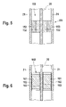
- FIG. 5 illustrates schematically a seal assembly including a first region and a second region.
- FIG. 6 illustrates schematically a seal assembly including first and/or second layers.
- FIG. 1 shows a part of a gas sensor 10 , e.g. an electrochemical sensor for determining the oxygen concentration in an exhaust gas of an internal combustion engine, or for determining the temperature of the exhaust gas of an engine.
- Gas sensor 10 includes a planar sensor element 20 arranged in a housing 21 .
- Sensor element 20 has a section 23 on the side of the gas to be analyzed and a terminal-side section 24 .
- contact surfaces 31 which are electrically connected to a measuring element 23 provided at measuring-gas-side section 22 of sensor-element 20 , are mounted to the outer surfaces of sensor element 20 .
- a contacting device not shown contacts contact surfaces 31 , the contacting device electrically connecting measuring element 23 to an evaluation circuit arranged outside the gas sensor, via a connector cable likewise not shown.
- a double-walled, protective tube 25 Fastened to the housing on the side facing measuring-gas-side section 23 of sensor element 20 is a double-walled, protective tube 25 , which has gas-access openings 26 that allow the measuring gas to access measuring-gas-side section 22 of sensor element 20 .
- Gas sensor 10 is arranged in an exhaust-pipe measuring opening not shown, and measuring-gas-side region 23 of sensor element 20 and protective tube 25 project into the exhaust pipe.
- a female screw or screw cap which acts upon a collar 32 and engages with a thread of the measuring opening of the exhaust pipe, is provided for attaching the gas sensor.
- a seal assembly 110 having a sealing element 111 is provided for sealing and supporting sensor element 20 in housing 21 .
- “Under seal assembly 110 ” is to be understood as a predefined region along the major axis of sensor element 20 , as well as along the inner wall of housing 21 . Along this predefined region, sealing element 111 completely fills up the space between sensor element 20 and housing 21 .
- the sealing element has a continuous material connection to sensor element 20 and housing 21 .
- FIGS. 2 , 3 , 4 a , 4 b , 5 , and 6 illustrate a partial section of the gas sensor represented in FIG. 1 .
- FIGS. 2 , 3 , 4 a , 4 b , 5 , and 6 illustrate a partial section of the gas sensor represented in FIG. 1 .
- FIGS. 2 , 3 , 4 a , 4 b , 5 , and 6 illustrate a partial section of the gas sensor represented in FIG. 1 .
- FIGS. 2 , 3 , 4 a , 4 b , 5 , and 6 illustrate a partial section of the gas sensor represented in FIG. 1 .
- FIGS. 2 , 3 , 4 a , 4 b , 5 , and 6 illustrate a partial section of the gas sensor represented in FIG. 1 .
- FIGS. 2 , 3 , 4 a , 4 b , 5 , and 6 illustrate a partial section of the gas sensor represented in FIG. 1 .
- Seal assembly 120 represented in FIG. 2 includes a machined, metallic part 121 and a sealing element 122 .
- Machined part 121 is shaped similarly to a cup and has a side wall 123 and a base 125 .
- Side wall 123 has a circular cross-section corresponding to the shape of housing 21 and forms a hollow cylinder.
- Machined, metallic part 121 is closed on at least one end by a base 125 .
- Base 125 is planar in accordance with the base of a pot.
- Base 125 may also be configured to have a different shape that is tapered with respect to side wall 123 , e.g. hemispherical or conical.
- Base 125 of machined part 121 has a central opening 126 for receiving sensor element 20 .
- sensor element 20 is arranged on the axis of symmetry of hollow cylindrical side wall 123 of machined part 121 .
- the region between sensor element 20 and machined part 121 is filled in by a sealing element 122 .
- Sealing element 122 may also be provided in the region of opening 126 of machined part 121 .
- Side wall 123 of machined part 121 rests against the inner wall of housing 21 , and the machined part may be connected to housing 21 by one or more welded connections 124 (e.g. using laser welding).
- Seal assembly 130 again includes a machined part 131 , which is shaped similarly to a cup, is filled by a sealing element 132 , and has a side wall and a base. The side wall is joined to housing 21 by welded connections 134 .
- the base has a central opening, in which an insulating element 133 made out of, for example, a ceramic material is provided.
- the insulating element has, in turn, a central opening for receiving sensor element 20 .
- insulating element 133 is wider than the base opening of machined part 131 , so that it may rest on the base of machined part 131 .
- FIGS. 4 a and 4 b represent a further modification of the seal assembly, FIG. 4 b being a sectional view of seal assembly 140 along line IVb-IVb in FIG. 4 a .
- Seal assembly 140 includes a first sealing element 141 , a hollow cylindrical body 142 , and a second sealing element 143 .
- the interior of body 142 forms an opening 144 for receiving sensor element 20 and second sealing element 143 .
- Body 142 contains, for example, a ceramic and/or a metallic material. The dimensions of body 142 are selected so that it may be spaced apart from housing 21 and sensor element 20 .
- First sealing element 141 is provided in the gap between body 142 and housing 21
- second sealing element 143 is provided in the gap between body 142 and sensor element 20 .
- Opening 144 of body 142 is shaped so that its cross-section (in the plane perpendicular to the major axis of sensor element 20 ) corresponds to the correspondingly enlarged cross-section of sensor element 20 .
- sealing element 151 has a first region 152 and a second region 153 .
- First region 152 of sealing element 151 surrounds sensor element 20 .
- Second region 153 of sealing element 151 is provided between first region 152 and housing 21 . Consequently, the first region is in contact with sensor element 20 , and the second region is in contact with housing 21 .
- First region 152 of sealing element 151 has, as a main component, a ceramic material that forms a continuous material connection to the ceramic sensor element.
- second region 153 of the sensor element includes, as a main component, a metallic material that forms a continuous material connection to metallic housing 21 .
- Sealing element 151 may alternatively have a high metallic fraction adjacent to housing 21 and a high ceramic fraction adjacent to sensor element 20 , the metallic fraction of sealing element 151 decreasing in steps, or continuously, from housing 21 to sensor element 20 , and the ceramic fraction of sealing element 151 increasing in steps, or continuously, from housing 21 to sensor element 20 .
- first layer 162 is provided between sealing element 161 and housing 21
- second layer 163 is provided between sealing element 161 and sensor element 20 .
- First and second layers 162 , 163 may contain, for example, glass or ceramic material and are used for insulating and improving adhesion.
- first layer 162 is configured as an intermediate layer, includes aluminum oxide and/or zirconium oxide and/or aluminum phosphate, and has a thickness of 50 to 200 ⁇ m, such as, for example, 100 ⁇ m.
- An intermediate layer may alternatively be provided between sealing element 122 , 132 , 141 , 143 and another metallic element 121 , 131 , 142 of gas sensor 10 .
- This intermediate layer 162 may prevent cracks from forming in the sealing element during the heat treatment as a result of a reaction of the ceramic material with the metallic material of the housing.
- sealing elements 111 , 122 , 132 , 141 , 143 , 151 , 161 of seal assemblies 110 , 120 , 130 , 140 , 150 , 160 represented in FIGS. 1 through 6 contain a ceramic material at a level of 80 to 100 weight percent and a glass fraction of 0 to 20 weight percent. If a particularly good insulation between the sensor element and housing (greater than or equal to 1 M ⁇ ) is required for the operation of sensor element 20 , then a glass fraction of less than 3 weight percent may be desired.
- sealing elements 111 , 122 , 132 , 141 , 143 , 151 , 161 include a metallic material at a level of 30 to 100 weight percent, such as, for example, 60 weight percent, and a ceramic material at a level of 0 to 70 weight percent, such as, for example, 40 weight percent.
- the starting material of sealing element 111 , 122 , 132 , 141 , 143 , 151 , 161 is subjected to a heat treatment, during which sealing element 111 , 122 , 132 , 141 , 143 , 151 , 161 forms.
- the heat treatment may cause the volume of sealing element 111 , 122 , 132 , 141 , 143 , 151 , 161 to decrease by a maximum of 5 percent, or even to increase.
- the volume of the starting material of sealing element 111 , 122 , 132 , 141 , 143 , 151 , 161 prior to the heat treatment is to be compared to the volume of sealing element 111 , 122 , 132 , 141 , 143 , 151 , 161 after the heat treatment.
- sealing element 111 , 122 , 132 , 141 , 143 , 151 , 161 may develop a closed porosity with a pore fraction in the range of 15 to 50 volume percent, in particular 35 volume percent.
- the average pore size of sealing element 111 , 122 , 132 , 141 , 143 , 151 , 161 may lie in the range of 20 to 40 ⁇ m, such as, for example, 30 ⁇ m. Over 90 percent of the pores may have a pore size in the range of 10 to 60 ⁇ m.
- a ceramic material having a coefficient of thermal expansion ⁇ >7 ⁇ 10 ⁇ 6 /K and a resistivity of >10 10 Ohm may be selected.
- sealing element 111 , 122 , 132 , 141 , 143 , 151 , 161 may be inserted into housing 21 as a preformed element.
- sealing element 111 , 122 , 132 , 141 , 143 , 151 , 161 may initially be positioned on sensor element 20 , and sealing element 111 , 122 , 132 , 141 , 143 , 151 , 161 and sensor element 20 may then be inserted into housing 21 as a unit.
- sensor element 20 is positioned inside housing 21 , and the starting material of sealing element 111 , 122 , 132 , 141 , 143 , 151 , 161 is introduced by an injection-molding process.
- the heat treatment of sealing element 122 , 132 may also be performed outside of the housing.
- sensor element 20 and sealing element 122 , 132 and, if applicable, insulating element 133 are to be initially introduced into machined, metallic part 121 , 131 , and the above-mentioned elements are to be subsequently subjected to the heat treatment. Due to the heat treatment, the named elements join to form a unit, which may be inserted into housing 20 . Subsequently, machined, metallic part 121 , 131 may be joined to housing 20 in a gas-tight manner, by welding (e.g. laser welding or resistance welding, etc.) or soldering, etc.
- welding e.g. laser welding or resistance welding, etc.
- sensor element 20 , body 142 , second sealing element 143 , and, if applicable, first sealing element 141 are subjected to a heat treatment outside of housing 20 .
- the unit formed from the named elements by the heat treatment is then to be installed in housing 20 .
- housing 20 may be joined in a gas-tight manner to the one first sealing element 141 having a high metallic fraction.
- first sealing element 141 may initially be subjected to a heat treatment in housing 20 , which, for example, may occur at a lower temperature than the heat treatment outside of housing 20 .
- the second heat treatment may allow first sealing element 141 to form a gas-tight, integral connection to housing 20 and body 142 .
Landscapes
- Chemical & Material Sciences (AREA)
- Life Sciences & Earth Sciences (AREA)
- Health & Medical Sciences (AREA)
- Physics & Mathematics (AREA)
- Chemical Kinetics & Catalysis (AREA)
- Electrochemistry (AREA)
- Molecular Biology (AREA)
- Analytical Chemistry (AREA)
- Biochemistry (AREA)
- General Health & Medical Sciences (AREA)
- General Physics & Mathematics (AREA)
- Immunology (AREA)
- Pathology (AREA)
- Measuring Oxygen Concentration In Cells (AREA)
Priority Applications (1)
| Application Number | Priority Date | Filing Date | Title |
|---|---|---|---|
| US11/881,639 US8038933B2 (en) | 2002-05-23 | 2007-07-26 | Gas sensor |
Applications Claiming Priority (2)
| Application Number | Priority Date | Filing Date | Title |
|---|---|---|---|
| DE10222789A DE10222789B4 (de) | 2002-05-23 | 2002-05-23 | Gasmeßfühler |
| DE10222789.6 | 2002-05-23 |
Related Child Applications (1)
| Application Number | Title | Priority Date | Filing Date |
|---|---|---|---|
| US11/881,639 Division US8038933B2 (en) | 2002-05-23 | 2007-07-26 | Gas sensor |
Publications (2)
| Publication Number | Publication Date |
|---|---|
| US20040040843A1 US20040040843A1 (en) | 2004-03-04 |
| US7258770B2 true US7258770B2 (en) | 2007-08-21 |
Family
ID=29432228
Family Applications (2)
| Application Number | Title | Priority Date | Filing Date |
|---|---|---|---|
| US10/444,759 Expired - Fee Related US7258770B2 (en) | 2002-05-23 | 2003-05-23 | Gas sensor |
| US11/881,639 Expired - Fee Related US8038933B2 (en) | 2002-05-23 | 2007-07-26 | Gas sensor |
Family Applications After (1)
| Application Number | Title | Priority Date | Filing Date |
|---|---|---|---|
| US11/881,639 Expired - Fee Related US8038933B2 (en) | 2002-05-23 | 2007-07-26 | Gas sensor |
Country Status (3)
| Country | Link |
|---|---|
| US (2) | US7258770B2 (de) |
| JP (1) | JP4603772B2 (de) |
| DE (1) | DE10222789B4 (de) |
Cited By (3)
| Publication number | Priority date | Publication date | Assignee | Title |
|---|---|---|---|---|
| US20080258401A1 (en) * | 2004-08-12 | 2008-10-23 | Martin Cotton | Seal Arrangement |
| US20140106181A1 (en) * | 2012-10-15 | 2014-04-17 | King Saud University | Foam material and method for the preparation thereof |
| US9719884B2 (en) | 2012-12-20 | 2017-08-01 | Robert Bosch Gmbh | Intake gas sensor for internal combustion engine |
Families Citing this family (20)
| Publication number | Priority date | Publication date | Assignee | Title |
|---|---|---|---|---|
| CN100416265C (zh) * | 2003-06-27 | 2008-09-03 | 日本特殊陶业株式会社 | 传感器的制造方法和传感器 |
| WO2005090960A1 (ja) * | 2004-03-19 | 2005-09-29 | Ngk Spark Plug Co., Ltd. | ガスセンサ |
| DE102005051704A1 (de) * | 2005-10-28 | 2007-05-03 | Robert Bosch Gmbh | Gasmessfühler und Verfahren zur Herstellung des Gasmessfühlers |
| US8147667B2 (en) * | 2006-12-20 | 2012-04-03 | Robert Bosch Gmbh | Exhaust gas sensor and method of manufacture |
| US9447503B2 (en) * | 2007-05-30 | 2016-09-20 | United Technologies Corporation | Closed pore ceramic composite article |
| CN102265148A (zh) * | 2009-03-02 | 2011-11-30 | 日本特殊陶业株式会社 | 气体传感器的制造方法及气体传感器 |
| DE102011051200A1 (de) * | 2011-06-20 | 2012-12-20 | Priamus System Technologies Ag | Sensor |
| DE102012110845A1 (de) * | 2012-11-12 | 2014-05-15 | Epcos Ag | Temperaturfühler und Verfahren zur Herstellung eines Temperaturfühlers |
| US9297791B2 (en) | 2012-12-20 | 2016-03-29 | Robert Bosch Gmbh | Gas sensor with thermal shock protection |
| DE102013222594A1 (de) * | 2013-03-12 | 2014-09-18 | Robert Bosch Gmbh | Spezielle Dichtungsgeometrie bei Abgassensoren zur Erzeugung einer hohen Dichtigkeit |
| DE102013205037A1 (de) * | 2013-03-21 | 2014-09-25 | Robert Bosch Gmbh | Sensorelement und Abgassensor aufweisend ein Sensorelement |
| DE102013211793A1 (de) * | 2013-06-21 | 2014-12-24 | Robert Bosch Gmbh | Sensorelement mit Leiterbahn und Referenzgaskanal |
| DE102014107781A1 (de) * | 2014-06-03 | 2015-12-03 | Endress + Hauser Gmbh + Co. Kg | Vorrichtung zur Bestimmung oder Überwachung einer physikalischen oder chemischen Prozessgröße |
| CN107209148A (zh) * | 2014-12-15 | 2017-09-26 | 阿克米-工程股份公司 | 用于气体和液体介质的氢检测器 |
| DE102015223949B4 (de) * | 2015-12-01 | 2020-09-24 | TE Connectivity Sensors Germany GmbH | Sensoranordnung für ein Widerstandsthermometer, Widerstandsthermometer und Verfahren zur Herstellung einer Sensoranordnung |
| DE102015223951B4 (de) * | 2015-12-01 | 2022-12-01 | TE Connectivity Sensors Germany GmbH | Substrat für eine Sensoranordnung für ein Widerstandsthermometer, Sensoranordnung und Widerstandsthermometer |
| DE102015223948B3 (de) * | 2015-12-01 | 2017-03-30 | TE Connectivity Sensors Germany GmbH | Substrat für eine Sensoranordnung für ein Widerstandsthermometer, Sensoranordnung, Widerstandsthermometer und Verfahren zur Herstellung eines solchen Substrats |
| DE102015223950A1 (de) * | 2015-12-01 | 2017-06-01 | TE Connectivity Sensors Germany GmbH | Substrat für eine Sensoranordnung für ein Widerstandsthermometer, Sensoranordnung, Widerstandsthermometer und Verfahren zur Herstellung eines solchen Substrats |
| JP6890061B2 (ja) * | 2017-07-31 | 2021-06-18 | 日本特殊陶業株式会社 | ガスセンサ |
| JP6988850B2 (ja) * | 2019-03-14 | 2022-01-05 | 株式会社デンソー | ガスセンサの製造方法 |
Citations (7)
| Publication number | Priority date | Publication date | Assignee | Title |
|---|---|---|---|---|
| DE4126378A1 (de) | 1990-10-26 | 1992-04-30 | Bosch Gmbh Robert | Gasmessfuehler, insbesondere zur bestimmung des sauerstoffgehaltes in abgasen von brennkraftmaschinen |
| US5467636A (en) | 1994-09-27 | 1995-11-21 | General Motors Corporation | Flat plate sensor with a robust package design |
| DE19532090A1 (de) | 1995-08-30 | 1997-03-06 | Bosch Gmbh Robert | Dichtung für ein Sensorelement eines Gassensors |
| US5755941A (en) * | 1995-01-04 | 1998-05-26 | Robert Bosch Gmbh | Electrochemical measuring element |
| DE19852674A1 (de) | 1998-11-16 | 2000-05-18 | Bosch Gmbh Robert | Dichtung für ein Sensorelement eines Gassensors und Verfahren zur Herstellung der Dichtung |
| US6206377B1 (en) * | 1998-04-01 | 2001-03-27 | Robert Bosch Gmbh | Seal arrangement for a sensing element of a gas sensor |
| DE10123168C1 (de) | 2001-05-12 | 2002-11-07 | Bosch Gmbh Robert | Dichtungsanordnung für einen Gasmeßfühler und Verfahren zur Herstellung der Dichtungsanordnung |
Family Cites Families (14)
| Publication number | Priority date | Publication date | Assignee | Title |
|---|---|---|---|---|
| US3525894A (en) * | 1968-06-26 | 1970-08-25 | Gen Motors Corp | Spark plug with a conductive glass seal electrode of glass and a metal alloy |
| US3920172A (en) * | 1974-10-03 | 1975-11-18 | Bendix Corp | Conductive glass seal assembly |
| JPS5720656A (en) * | 1980-07-11 | 1982-02-03 | Nippon Denso Co Ltd | Detector for concentration of oxygen |
| JPH0637325Y2 (ja) * | 1989-05-15 | 1994-09-28 | 日本碍子株式会社 | 酸素センサ |
| MY114772A (en) * | 1994-07-05 | 2003-01-31 | Shell Int Research | Apparatus for cooling hot gas |
| US5647636A (en) * | 1995-09-12 | 1997-07-15 | Seating Innovations L.L.C. | Suspended seating device |
| DE19603379A1 (de) * | 1996-01-31 | 1997-08-07 | Bosch Gmbh Robert | Gassensor |
| DE19605290C2 (de) * | 1996-02-14 | 1998-02-26 | Bosch Gmbh Robert | Meßfühler |
| DE19707458A1 (de) * | 1997-02-25 | 1998-08-27 | Bosch Gmbh Robert | Meßfühler und Verfahren zu dessen Herstellung |
| DE19707456A1 (de) * | 1997-02-25 | 1998-08-27 | Bosch Gmbh Robert | Meßfühler und Verfahren zu dessen Herstellung |
| DE19714203C2 (de) * | 1997-04-07 | 2000-06-29 | Bosch Gmbh Robert | Dichtelement für Sensoren |
| AU7690698A (en) * | 1997-05-20 | 1998-12-11 | Zymequest, Inc. | Cell processing systems |
| DE19850959A1 (de) * | 1998-11-05 | 2000-05-11 | Bosch Gmbh Robert | Meßfühler und Verfahren zu seiner Herstellung |
| EP1120645A3 (de) * | 2000-01-27 | 2004-07-07 | Ngk Spark Plug Co., Ltd. | Gassensor |
-
2002
- 2002-05-23 DE DE10222789A patent/DE10222789B4/de not_active Expired - Fee Related
-
2003
- 2003-05-21 JP JP2003144061A patent/JP4603772B2/ja not_active Expired - Fee Related
- 2003-05-23 US US10/444,759 patent/US7258770B2/en not_active Expired - Fee Related
-
2007
- 2007-07-26 US US11/881,639 patent/US8038933B2/en not_active Expired - Fee Related
Patent Citations (11)
| Publication number | Priority date | Publication date | Assignee | Title |
|---|---|---|---|---|
| DE4126378A1 (de) | 1990-10-26 | 1992-04-30 | Bosch Gmbh Robert | Gasmessfuehler, insbesondere zur bestimmung des sauerstoffgehaltes in abgasen von brennkraftmaschinen |
| US5467636A (en) | 1994-09-27 | 1995-11-21 | General Motors Corporation | Flat plate sensor with a robust package design |
| EP0706046A1 (de) | 1994-09-27 | 1996-04-10 | General Motors Corporation | Planarer Fühler mit unverwüstlicher Packung |
| US5755941A (en) * | 1995-01-04 | 1998-05-26 | Robert Bosch Gmbh | Electrochemical measuring element |
| DE19532090A1 (de) | 1995-08-30 | 1997-03-06 | Bosch Gmbh Robert | Dichtung für ein Sensorelement eines Gassensors |
| US5846391A (en) | 1995-08-30 | 1998-12-08 | Robert Bosch Gmbh | Seal for a sensor element of a gas sensor |
| US6206377B1 (en) * | 1998-04-01 | 2001-03-27 | Robert Bosch Gmbh | Seal arrangement for a sensing element of a gas sensor |
| DE19852674A1 (de) | 1998-11-16 | 2000-05-18 | Bosch Gmbh Robert | Dichtung für ein Sensorelement eines Gassensors und Verfahren zur Herstellung der Dichtung |
| US6474655B1 (en) | 1998-11-16 | 2002-11-05 | Robert Bosch Gmbh | Seal for a sensor element of a gas sensor and method for producing said seal |
| DE10123168C1 (de) | 2001-05-12 | 2002-11-07 | Bosch Gmbh Robert | Dichtungsanordnung für einen Gasmeßfühler und Verfahren zur Herstellung der Dichtungsanordnung |
| US20030015020A1 (en) | 2001-05-12 | 2003-01-23 | Heinz Geier | Sealing system for a gas sensor and a method for manufacturing the sealing system |
Non-Patent Citations (4)
| Title |
|---|
| C. Koemer et al., "Processing of Metal Foams-Challenges and Opportunities," Advanced Engineering Materials 2000, 2, No. 4, pp. 159-191. |
| G. S. Grader et al., "Novel Ceramic Foams From Crystals of AlCl<SUB>3</SUB>(pr<SUP>i</SUP><SUB>2</SUB>O) Complex," Journal of Materials Research, vol. 14. No. 4, Apr. 1999, pp. 1485-1949. |
| J. Brandt et al., "Processing of Mullite-Based Long-Fibre Composites Via Slurry Routes and by Oxidation of an Al-Si Alloy Powder," Journal of the European Ceramic Society, 16 (1996), pp. 261-267. |
| N. Claussen et al., "Low-Shrinkage Reaction-Bonded Alumina," Journal of the European Ceramic Society, 5 (1989), pp. 29-35. |
Cited By (5)
| Publication number | Priority date | Publication date | Assignee | Title |
|---|---|---|---|---|
| US20080258401A1 (en) * | 2004-08-12 | 2008-10-23 | Martin Cotton | Seal Arrangement |
| US7969308B2 (en) * | 2004-08-12 | 2011-06-28 | Martin Cotton | Seal arrangement |
| US20140106181A1 (en) * | 2012-10-15 | 2014-04-17 | King Saud University | Foam material and method for the preparation thereof |
| US9114457B2 (en) * | 2012-10-15 | 2015-08-25 | King Saud University | Foam material and method for the preparation thereof |
| US9719884B2 (en) | 2012-12-20 | 2017-08-01 | Robert Bosch Gmbh | Intake gas sensor for internal combustion engine |
Also Published As
| Publication number | Publication date |
|---|---|
| US20070266735A1 (en) | 2007-11-22 |
| JP2003344355A (ja) | 2003-12-03 |
| US20040040843A1 (en) | 2004-03-04 |
| US8038933B2 (en) | 2011-10-18 |
| JP4603772B2 (ja) | 2010-12-22 |
| DE10222789B4 (de) | 2006-12-07 |
| DE10222789A1 (de) | 2003-12-11 |
Similar Documents
| Publication | Publication Date | Title |
|---|---|---|
| US8038933B2 (en) | Gas sensor | |
| US6347543B1 (en) | Measuring sensor and method for its fabrication | |
| US7891870B2 (en) | Temperature sensor element and method of manufacturing the same | |
| JP3800978B2 (ja) | ガスセンサ及びその製造方法 | |
| US20020172258A1 (en) | Temperature sensor and production method thereof | |
| JPH08114574A (ja) | 排気センサ | |
| CN102388508A (zh) | 耐高压气密密封端子及其制造方法 | |
| US6223583B1 (en) | Sensor element seal for a detector | |
| US4532492A (en) | Temperature-compensated, oxygen-content gas sensor | |
| US6040519A (en) | Unit sheath | |
| JP2002530645A (ja) | ガスセンサのセンサ素子に用いられるシール機構および該シール機構を製造するための方法 | |
| US20120114939A1 (en) | Ceramic Component and Fabrication Method | |
| WO2000024039A1 (fr) | Lampe et enveloppe de lampe fabriquee dans un materiau a gradient fonctionnel | |
| US7309848B2 (en) | Sealing structure of ceramic heater | |
| US6255626B1 (en) | Glow plug and process for its manufacture | |
| US4596132A (en) | Gas component detecting plug | |
| JP3655454B2 (ja) | センサのリード線封止構造 | |
| US7132798B2 (en) | Joined bodies, high pressure discharge lamps and assemblies therefor | |
| US6392199B1 (en) | Glow plug and process for its manufacture | |
| JP6276488B1 (ja) | 温度センサ | |
| CN100499939C (zh) | 陶瓷加热器 | |
| JP2000171308A (ja) | 温度センサおよびその製造方法 | |
| JP2000502456A (ja) | センサ用のシール部材及びその製造方法 | |
| JP2000298112A (ja) | ガス媒体用センサ装置 | |
| WO2019172330A1 (ja) | ガスセンサ素子およびガスセンサ |
Legal Events
| Date | Code | Title | Description |
|---|---|---|---|
| AS | Assignment |
Owner name: ROBERT BOSCH GMBH, GERMANY Free format text: ASSIGNMENT OF ASSIGNORS INTEREST;ASSIGNORS:WEYL, HELMUT;DE LA PRIETA, CLAUDIO;HACHTEL ANDREAS;AND OTHERS;REEL/FRAME:014558/0548;SIGNING DATES FROM 20030704 TO 20030907 |
|
| STCF | Information on status: patent grant |
Free format text: PATENTED CASE |
|
| FPAY | Fee payment |
Year of fee payment: 4 |
|
| FPAY | Fee payment |
Year of fee payment: 8 |
|
| FEPP | Fee payment procedure |
Free format text: MAINTENANCE FEE REMINDER MAILED (ORIGINAL EVENT CODE: REM.); ENTITY STATUS OF PATENT OWNER: LARGE ENTITY |
|
| LAPS | Lapse for failure to pay maintenance fees |
Free format text: PATENT EXPIRED FOR FAILURE TO PAY MAINTENANCE FEES (ORIGINAL EVENT CODE: EXP.); ENTITY STATUS OF PATENT OWNER: LARGE ENTITY |
|
| STCH | Information on status: patent discontinuation |
Free format text: PATENT EXPIRED DUE TO NONPAYMENT OF MAINTENANCE FEES UNDER 37 CFR 1.362 |
|
| FP | Lapsed due to failure to pay maintenance fee |
Effective date: 20190821 |