US7161125B2 - Cooking appliance - Google Patents
Cooking appliance Download PDFInfo
- Publication number
- US7161125B2 US7161125B2 US11/028,847 US2884705A US7161125B2 US 7161125 B2 US7161125 B2 US 7161125B2 US 2884705 A US2884705 A US 2884705A US 7161125 B2 US7161125 B2 US 7161125B2
- Authority
- US
- United States
- Prior art keywords
- cooking appliance
- heating
- heating chamber
- main unit
- receptacle
- Prior art date
- Legal status (The legal status is an assumption and is not a legal conclusion. Google has not performed a legal analysis and makes no representation as to the accuracy of the status listed.)
- Active
Links
Images


Classifications
-
- H—ELECTRICITY
- H05—ELECTRIC TECHNIQUES NOT OTHERWISE PROVIDED FOR
- H05B—ELECTRIC HEATING; ELECTRIC LIGHT SOURCES NOT OTHERWISE PROVIDED FOR; CIRCUIT ARRANGEMENTS FOR ELECTRIC LIGHT SOURCES, IN GENERAL
- H05B6/00—Heating by electric, magnetic or electromagnetic fields
- H05B6/64—Heating using microwaves
- H05B6/76—Prevention of microwave leakage, e.g. door sealings
- H05B6/763—Microwave radiation seals for doors
-
- F—MECHANICAL ENGINEERING; LIGHTING; HEATING; WEAPONS; BLASTING
- F24—HEATING; RANGES; VENTILATING
- F24C—DOMESTIC STOVES OR RANGES ; DETAILS OF DOMESTIC STOVES OR RANGES, OF GENERAL APPLICATION
- F24C15/00—Details
- F24C15/02—Doors specially adapted for stoves or ranges
-
- F—MECHANICAL ENGINEERING; LIGHTING; HEATING; WEAPONS; BLASTING
- F24—HEATING; RANGES; VENTILATING
- F24C—DOMESTIC STOVES OR RANGES ; DETAILS OF DOMESTIC STOVES OR RANGES, OF GENERAL APPLICATION
- F24C15/00—Details
- F24C15/02—Doors specially adapted for stoves or ranges
- F24C15/027—Doors specially adapted for stoves or ranges located at bottom side of housing
-
- F—MECHANICAL ENGINEERING; LIGHTING; HEATING; WEAPONS; BLASTING
- F24—HEATING; RANGES; VENTILATING
- F24C—DOMESTIC STOVES OR RANGES ; DETAILS OF DOMESTIC STOVES OR RANGES, OF GENERAL APPLICATION
- F24C15/00—Details
- F24C15/16—Shelves, racks or trays inside ovens; Supports therefor
- F24C15/162—Co-operating with a door, e.g. operated by the door
-
- H—ELECTRICITY
- H05—ELECTRIC TECHNIQUES NOT OTHERWISE PROVIDED FOR
- H05B—ELECTRIC HEATING; ELECTRIC LIGHT SOURCES NOT OTHERWISE PROVIDED FOR; CIRCUIT ARRANGEMENTS FOR ELECTRIC LIGHT SOURCES, IN GENERAL
- H05B6/00—Heating by electric, magnetic or electromagnetic fields
- H05B6/64—Heating using microwaves
- H05B6/6414—Aspects relating to the door of the microwave heating apparatus
Definitions
- the present invention generally relates to a cooking appliance, and more particularly, to a cooking appliance with a drawer in which an item to be heated is placed, wherein the drawer can be withdrawn from the main unit of the cooking appliance.
- Such a conventional drawer-type cooking appliance employing a configuration that allows the heating item mounting unit of a heating chamber to be pulled out is proposed in, for example, Japanese Patent Laying-Open Nos. 03-045820, 06-109257, and 11-237053.
- the door closure device of the cooking appliance disclosed in Japanese Patent Laying-Open No. 03-045820 includes a main unit with a cooking chamber in which an item to be heated is placed, a door shielding the cooking chamber from the atmosphere, a bottom panel in cooperation with the door, and a slide mechanism for sliding the bottom panel smoothly.
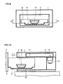
- FIG. 11 is a schematic side sectional view of the door closure device of the conventional cooking appliance disclosed therein.
- a main unit 1 includes a heating chamber 3
- the closure device is adapted to pull out/push in a drawer unit 2 including a door 4 and a bottom panel 16 from/into a heating chamber 3 by means of a slide mechanism.
- An item to be heated 6 is placed on bottom panel 16 .
- the slide mechanism is adapted such that rollers 17 and 18 fixed in heating chamber 3 of main unit 1 sandwich a bent of bottom panel 16 .
- Japanese Patent Laying-Open No. 06-109257 discloses a cooking appliance with a drawer in which an item to be heated is placed, wherein the drawer can be withdrawn from the main unit of the cooking appliance.
- detection means for detecting pull-out of the drawer upset of the cooking appliance is obviated to allow a drawer-type cooking appliance to be used in always a stable state.
- FIG. 12 is a schematic side sectional view of the conventional microwave oven disclosed therein.
- a heating receptacle 5 having an opening at the top is provided so as to be withdrawn arbitrarily from a main unit 1 .
- An item to be heated 6 is placed in heating receptacle 5 .
- a lid 19 covering the opening of heating receptacle 5 , heating receptacle 5 and provided at the main unit side 1 constitute a heating chamber 3 that shuts microwaves.
- bottom panel 16 can slide within heating chamber 3 by being sandwiched between the two rollers 17 and 18 fixed within heating chamber 3 of main unit 1 . Since the slide mechanism is provided inside the heating chamber, the components constituting the slide mechanism will be heated to a high temperature corresponding to the interior of the heating chamber attaining a high temperature during the heating process of the item to be heated. Accordingly, the slide mechanism must be formed by costly components and/or material that is highly heat-resistant and fire-resistant, leading to the problem of increase in the fabrication cost. Furthermore, provision of the slide mechanism in the heating chamber constitutes a factor for causing discharge by microwaves.
- Japanese Patent Laying-Open Nos. 06-109257 and 11-237053 are silent about a slide mechanism to smoothly withdraw a drawer unit from the main unit, a configuration of such a mechanism, and the site of arrangement thereof.
- an object of the present invention is to provide a cooking appliance of a configuration that allows the heating item mounting unit of a heating chamber to be pulled out, and that can prevent occurrence of discharge by microwaves, without having to form a slide mechanism with a component or material that has high heat-resistance and fire-resistance.
- a cooking appliance includes a main unit with a heating chamber, a drawer unit arranged to move in the main unit so as to be pulled outside the heating chamber of the main unit, and a transfer mechanism to transfer the drawer unit in the main unit.
- the transfer mechanism is provided outside the heating chamber.
- the transfer mechanism is provided outside the heating chamber in the cooking appliance of the present invention, it is not necessary to employ costly components and/or material that has high heat-resistance and fire-resistance to form the transfer mechanism. Therefore, the fabrication cost can be reduced.
- the transfer mechanism is not affected by the microwaves emitted in the heating chamber. Therefore, there is no possibility of discharge by microwaves.
- the drawer unit includes a door, and a heating receptacle in which an item to be heated is held.
- the door of the drawer unit is preferably supported on the main unit outside the heating chamber by the transfer mechanism. In this case, the drawer will not tip forward when pulled out from the heating chamber of the main unit since the drawer unit is supported on the main unit by the transfer mechanism. Thus, the drawer unit can be pulled out in a stable manner.
- the door of the drawer unit is preferably supported on the main unit by the left and right sidewalls and the bottom wall outside the heating chamber via the transfer mechanism. Since the drawer unit is supported on the main unit by at least 3 sites, a configuration that allows the drawer unit to be withdrawn smoothly and stably can be realized.
- the transfer mechanism preferably includes a fixed rail attached to the main unit, and a movable rail attached to the door of the drawer unit.
- the drawer unit includes a door, and a heating receptacle in which an item to be heated is held.
- the inner side of the bottom of the heating receptacle preferably has a concave.
- the drawer unit includes a door, a heating receptacle in which an item to be heated is held, and a mounting arranged in the heating receptacle, and on which an item to be heated is placed. It is preferable that the mounting can be removed from the heating receptacle. Such a configuration allows ease of cleaning. Since the liquid from the heating item that splashes out, when spilt out through the pulling in/pulling out movement of the drawer unit or during the heating process, will remain within the mounting, only the mounting has to be removed from the drawer unit to be wiped off or directly washed for cleaning.
- the inner side of the bottom of the heating receptacle has a concave
- the mounting preferably has a configuration that fits the concave of the inner side of the bottom of the heating receptacle.
- the rear wall of the heating receptacle is preferably set lower than the height of the left and right walls. Such a configuration allows ease of cleaning. Even in the case where liquid splashed out from the item to be heated adheres to the ceiling of the heating chamber, the ceiling of the heating chamber can be easily wiped with the drawer unit in a pulled-out state. Thus, a cooking appliance that can easily be cleaned is provided.
- FIG. 1 is a schematic perspective view of an appearance of a cooking appliance according to a first embodiment of the present invention.
- FIG. 2 is a side sectional view of the cooking appliance of the first embodiment of the present invention in a direction parallel to the pulling out direction of the drawer unit.
- FIG. 3 is a plan sectional view of the cooking appliance of the first embodiment of the present invention in a direction parallel to the pulling out direction of the drawer unit.
- FIG. 4 is a plan sectional view of a cooking appliance according to a second embodiment of the present invention in a direction parallel to the pulling direction of the drawer unit.
- FIGS. 5 , 6 and 7 are side sectional views of a cooking appliance according to a third embodiment, a fourth embodiment, and a fifth embodiment, respectively, of the present invention in a direction parallel to the pulling out direction of the drawer unit.
- FIGS. 8 and 9 are front sectional views of a cooking appliance according to a sixth embodiment and a seventh embodiment, respectively, of the present invention in a direction perpendicular to the pulling out direction of the drawer unit.
- FIG. 10 is a side sectional view of the cooking appliance of the sixth embodiment of the present invention in a direction parallel to the pulling out direction of the drawer unit.
- FIG. 11 is a schematic side sectional view of a door closure device of a conventional cooking appliance disclosed in Japanese Patent Laying-Open No. 03-045820.
- FIG. 12 is a schematic side sectional view of a conventional microwave oven disclosed in Japanese Patent Laying-Open No. 11-237053.
- a main unit 1 of a cooking appliance includes a heating chamber 3 to cook an item to be heated 6 .
- a drawer unit 2 is arranged in a movable manner, i.e. slidable manner, in main unit 1 so as to be withdrawn from heating chamber 3 of main unit 1 in the direction indicated by the arrow.
- the cooking appliance includes a slide rail 7 identified as the transfer mechanism to slide drawer unit 2 in main unit 1 .
- Drawer unit 2 includes a door 4 to open/close heating chamber 3 , and a heating receptacle 5 in which item 6 is placed and held.
- Heating receptacle 5 includes sidewalls at the left and right sides, a rear wall at the back in heating chamber 3 of main unit 1 , and an opening at the top.
- Door 4 is attached at the front of heating receptacle 5 . By closing heating chamber 3 through door 4 , the interior cavity of heating chamber 3 corresponds to a sealed cavity by the inner walls of main unit 1 and drawer unit 2 .
- Door 4 of drawer unit 2 is supported on main unit 1 by the left and right sidewall surfaces outside heating chamber 3 via slide rail 7 .
- Slide rail 7 includes a fixed rail 9 , and a movable rail 10 sliding along fixed rail 9 .
- Fixed rail 9 is attached at the left and right sidewall surfaces outside heating chamber 3 of main unit 1 .
- Movable rail 10 is attached to door 4 via an L-shape angle member 8 attached at the inner sidewall surface of door 4 so as to extend from the inner sidewall surface of door 4 of drawer unit 2 towards heating chamber 3 of main unit 1 .
- a microwave generator 11 is arranged above and at the rear side of heating chamber 3 in main unit 1 .
- Microwave generator 11 includes a magnetron 12 arranged outside and behind heating chamber 3 for generating a microwave, and a waveguide 13 arranged above and outside heating chamber 3 for propagation of microwaves generated from magnetron 12 .
- the microwave generated at magnetron 12 is propagated through waveguide 13 to be supplied into heating chamber 3 via a feeding port 14 to heat item 6 placed in heating receptacle 5 of drawer unit 2 arranged in heating chamber 3 to perform cooking.
- slide rail 7 formed of fixed rail 9 and movable rail 10 identified as the transfer mechanism is provided at the left and right sidewall surfaces outside heating chamber 3 .
- slide rail 7 is disposed outside heating chamber 3 in a slidable manner in a channel provided at the left and right sides of heating chamber 3 in main unit 1 .
- This channel may be a cavity enclosed by the top wall, bottom wall, and sidewalls in main unit 1 .
- fixed rail 9 is attached to an inner wall surface of main unit 1 , outside and located closer to heating chamber 3 .
- slide rail 7 is provided outside heating chamber 3 , as a transfer mechanism for moving drawer unit 2 in main unit 1 , L-shape angle member 8 , fixed rail 9 and movable rail 10 constituting slide rail 7 do not have to be formed of a costly component or material having high heat-resistance and fire-resistance. Therefore, the fabrication cost can be reduced.
- slide rail 7 identified as the transfer mechanism is provided outside heating chamber 3 , slide rail 7 will not be affected by the microwaves emitted to heating in chamber 3 . Therefore, there is no possibility of discharge by microwaves.
- drawer unit 2 since drawer unit 2 is supported on main unit 1 by slide rail 7 , drawer unit 2 will not be tipped frontward when pulled out from heating chamber 3 of main unit 1 . Drawer unit 2 can be pulled out in a stable manner.
- FIG. 4 is a plan sectional view of a cooking appliance according to a second embodiment of the present invention in a direction parallel to the pulling out direction of the drawer unit.
- fixed rail 9 In comparison with the first embodiment in which fixed rail 9 is attached to the inner wall surface of main unit 1 outside and closer to heating chamber 3 , fixed rail 9 can be attached to an inner wall surface constituting the contour wall of main unit 1 outside and distant from heating chamber 3 as in the second embodiment shown in FIG. 4 .
- the advantages similar to those of the first embodiment can be attained for the second embodiment.
- FIG. 5 A cooking appliance according to a third embodiment of the present invention is shown in FIG. 5 .
- slide rail 15 includes a fixed rail 15 a and a movable rail 15 b sliding along fixed rail 15 a .
- Fixed rail 15 a is attached to the bottom wall surfaces outside heating chamber 3 of main unit 1 .
- Movable rail 15 b is attached to door 4 via an L-shaped angle member 8 a attached to the inner sidewall surface of door 4 so as to extend from the inner sidewall surface of door 4 of drawer unit 2 towards heating chamber 3 of main unit 1 .
- the third embodiment is characterized in that, as the transfer mechanism, slide rail 15 formed of fixed rail 15 a and movable rail 15 b is attached to the bottom wall surface outside heating chamber 3 , in addition to slide rail 7 formed of fixed rail 9 and movable rail 10 provided at the left and right sidewall surfaces outside heating chamber 3 .
- slide rail 15 is located outside heating chamber 3 in a slidable manner within a channel provided at the bottom of heating chamber 3 in main unit 1 . This channel may be a cavity enclosed by the top wall, bottom wall and sidewalls in main unit 1 .
- fixed rail 15 a is attached to the outside bottom wall surface outside heating chamber 3 of main unit 1 located closer to heating chamber 3 .
- drawer unit 2 Since drawer unit 2 is supported on main unit 1 by at least three sites, i.e., the left and right sidewall surfaces and the bottom wall surfaces outside heating chamber 3 , the problem of drawer 2 rattling shakedly with respect to main unit 1 , when pulled out from main unit 1 , can be obviated. A configuration that allows drawer unit 2 to be pulled out smoothly and stably can be realized.
- a rotator such as a roller, wheel and the like, or rolling elements such as a cam follower, roller bearing, and the like can be employed.
- FIG. 6 A cooking appliance according to a fourth embodiment of the present invention is shown in FIG. 6 .
- a concave is formed at an inner side of the bottom of a heating receptacle 5 a of drawer unit 2 .
- An item to be heated 6 a such as soup or sauce in a vessel is placed on the surface of this concave.
- the concave at the inner side of the bottom of heating receptacle 5 a is formed as a convex at the outer side of the bottom of heating receptacle 5 a . It is preferable that a concave is formed so as to be located at substantially the center of the inner bottom surface of heating receptacle 5 a .
- the bottom of heating receptacle 5 a is preferably formed such that the depth of the circumferential region becomes smaller in seeing inside, and the circumferential portion is concave in an annular manner, and the center portion protrudes in seeing outside.
- the liquid of item 6 a to be heated is liquid such as soup or sauce
- the liquid of item 6 a may be spilt out through the pulling in/pulling out movement of the drawer due to the inertia force or may be spilt out during the heating process.
- the spilt liquid will remain within the concave in heating receptacle 5 a , and will not fall on the floor or platform where main unit 1 is placed when drawer unit 2 is pulled out. Therefore, the area around the cooking appliance can be kept clean.
- FIG. 7 is side sectional view of a cooking appliance according to a fifth embodiment of the present invention in a direction parallel to the pulling out direction of the drawer unit.
- a cooking appliance includes a tray 21 as the mounting on which item 6 a to be heated is placed.
- Tray 21 has a configuration fitting the concave portion of the inner side of the bottom of heating receptacle 5 a , and can be removed from heating receptacle 5 a .
- the liquid of item 6 a to be heated when spilt out through the pulling in/pulling out movement of the drawer or spilt out during the heating process, will remain on tray 21 .
- the liquid will not fall on the platform or floor on which main unit 1 is installed when drawer unit 2 is pulled out. Therefore, the area around the cooking appliance can be kept clean.
- tray 21 will remain adhering to tray 21 that is removable from heating chamber 5 a . Therefore, tray 21 alone can be removed from drawer unit 2 to be wiped off, or tray 21 can be directly washed with water. Thus, a cooking appliance that can be easily cleaned is provided.
- FIGS. 8 and 9 are front sectional views of a cooking appliance according to a sixth embodiment and a seventh embodiment, respectively, of the present invention, in a direction perpendicular to pulling out direction of the drawer unit.
- FIG. 10 is a side sectional view of the cooking appliance of the sixth embodiment of the present invention in a direction parallel to the pulling out direction of the drawer unit.
- the height H 2 of rear wall of heating chamber 5 b is set lower than height H 1 of the left and right sidewalls in the sixth embodiment.
- the cooking appliance according to the seventh embodiment has left and right sidewalls of heating receptacle 5 c set as low as height H 2 of the rear wall, as shown in FIG. 9 .
- Advantages embodiment can be achieved herein.
- the transfer mechanism Since the costly component and/or material with high heat-resistance and fire-resistance to form the transfer mechanism is not required, the fabrication cost can be reduced. Furthermore, the possibility of discharge caused by microwaves is eliminated since the transfer mechanism is not affected by the microwaves emitted in the heating chamber.
Landscapes
- Engineering & Computer Science (AREA)
- Chemical & Material Sciences (AREA)
- Combustion & Propulsion (AREA)
- Mechanical Engineering (AREA)
- General Engineering & Computer Science (AREA)
- Physics & Mathematics (AREA)
- Electromagnetism (AREA)
- Electric Ovens (AREA)
- Electric Stoves And Ranges (AREA)
Applications Claiming Priority (4)
| Application Number | Priority Date | Filing Date | Title |
|---|---|---|---|
| JP2004002830 | 2004-01-08 | ||
| JP2004-002830(P) | 2004-01-08 | ||
| JP2004-007384(P) | 2004-01-14 | ||
| JP2004007384A JP4027325B2 (ja) | 2004-01-08 | 2004-01-14 | 加熱調理器 |
Publications (2)
| Publication Number | Publication Date |
|---|---|
| US20050173399A1 US20050173399A1 (en) | 2005-08-11 |
| US7161125B2 true US7161125B2 (en) | 2007-01-09 |
Family
ID=37309304
Family Applications (1)
| Application Number | Title | Priority Date | Filing Date |
|---|---|---|---|
| US11/028,847 Active US7161125B2 (en) | 2004-01-08 | 2005-01-04 | Cooking appliance |
Country Status (2)
| Country | Link |
|---|---|
| US (1) | US7161125B2 (ja) |
| JP (1) | JP4027325B2 (ja) |
Cited By (5)
| Publication number | Priority date | Publication date | Assignee | Title |
|---|---|---|---|---|
| US20060191925A1 (en) * | 2005-02-15 | 2006-08-31 | Masayuki Iwamoto | Built-in kitchen apparatus |
| US20080169735A1 (en) * | 2007-01-11 | 2008-07-17 | Sanden Corporation | Showcase |
| US20080302441A1 (en) * | 2007-06-06 | 2008-12-11 | Electrolux Home Products, Inc. | Storage compartment |
| US20170086261A1 (en) * | 2015-09-21 | 2017-03-23 | Guangdong Midea Kitchen Appliances Manufacturing Co., Ltd. | Microwave heating device and drawer door assembly used for the same |
| USD1021510S1 (en) | 2019-06-20 | 2024-04-09 | Whirlpool Corporation | Cooking appliance |
Families Citing this family (22)
| Publication number | Priority date | Publication date | Assignee | Title |
|---|---|---|---|---|
| JP4404714B2 (ja) * | 2004-07-23 | 2010-01-27 | シャープ株式会社 | 引き出し式加熱調理器 |
| JP4802055B2 (ja) * | 2006-07-20 | 2011-10-26 | 株式会社東芝 | 加熱調理器 |
| JP4404918B2 (ja) | 2007-06-14 | 2010-01-27 | シャープ株式会社 | 引き出し式加熱調理器 |
| JP4280783B2 (ja) | 2007-06-19 | 2009-06-17 | シャープ株式会社 | 引き出し式加熱調理器のドア開閉方法及び装置 |
| JP4378399B2 (ja) | 2007-07-25 | 2009-12-02 | シャープ株式会社 | 引き出し式加熱調理器における開閉ドアの開閉制御方法、及び引き出し式加熱調理器 |
| US8291816B2 (en) | 2008-06-04 | 2012-10-23 | Sharp Kabushiki Kaisha | Drawer type cooking device |
| US8048464B2 (en) * | 2008-07-14 | 2011-11-01 | Sabritas, S. De R.L. De C.V. | Molded expanded pellet product and method of making |
| JP2010071585A (ja) | 2008-09-19 | 2010-04-02 | Sharp Corp | 引出し型加熱調理器 |
| US8253084B2 (en) | 2008-11-28 | 2012-08-28 | Sharp Kabushiki Kaisha | Drawer type cooking device having turntable mechanism |
| JP2010133634A (ja) * | 2008-12-04 | 2010-06-17 | Sharp Corp | 引出し型加熱調理器 |
| JP2010181112A (ja) | 2009-02-06 | 2010-08-19 | Sharp Corp | 引出し型加熱調理器 |
| JP2010181102A (ja) | 2009-02-06 | 2010-08-19 | Sharp Corp | ビルトイン型加熱調理器 |
| JP2010181103A (ja) | 2009-02-06 | 2010-08-19 | Sharp Corp | ビルトイン型加熱調理器 |
| CN102538036B (zh) * | 2010-12-16 | 2016-08-10 | 乐金电子(天津)电器有限公司 | 微波炉 |
| JP2013116408A (ja) * | 2013-03-21 | 2013-06-13 | Mitsubishi Electric Corp | 調理装置 |
| CN105263379A (zh) * | 2013-06-04 | 2016-01-20 | 皇家飞利浦有限公司 | 基于空气的炸锅 |
| JP5882284B2 (ja) * | 2013-10-17 | 2016-03-09 | リンナイ株式会社 | 複合調理器 |
| US10154549B2 (en) | 2014-08-29 | 2018-12-11 | Sharp Kabushiki Kaisha | Heating cooker |
| US10462857B2 (en) * | 2015-09-21 | 2019-10-29 | Guangdong Midea Kitchen Appliances Manufacturing Co., Ltd. | Microwave heating device |
| CN106839011B (zh) * | 2017-02-27 | 2019-03-12 | 广东美的厨房电器制造有限公司 | 烹饪器具 |
| CN107334370B (zh) * | 2017-07-06 | 2023-04-28 | 珠海格力电器股份有限公司 | 一种支架组件及烹饪用具 |
| USD908416S1 (en) * | 2019-06-20 | 2021-01-26 | Whirlpool Corporation | Cooking appliance |
Citations (6)
| Publication number | Priority date | Publication date | Assignee | Title |
|---|---|---|---|---|
| US4335292A (en) * | 1979-05-09 | 1982-06-15 | Matsushita Electric Industrial Co., Ltd. | High frequency oven with drawer type door |
| US4814571A (en) * | 1987-04-27 | 1989-03-21 | Raytheon Company | Microwave oven adapted for under-the-counter use |
| JPH0345820A (ja) | 1989-07-11 | 1991-02-27 | Matsushita Electric Ind Co Ltd | 調理器の扉開閉装置 |
| JPH06109257A (ja) | 1992-09-28 | 1994-04-19 | Sanyo Electric Co Ltd | 加熱調理器 |
| JPH11237053A (ja) | 1998-02-20 | 1999-08-31 | Matsushita Electric Ind Co Ltd | 電子レンジ |
| US6166353A (en) * | 1997-08-22 | 2000-12-26 | White Consolidated Industries, Inc. | Free-standing warmer drawer |
-
2004
- 2004-01-14 JP JP2004007384A patent/JP4027325B2/ja not_active Expired - Fee Related
-
2005
- 2005-01-04 US US11/028,847 patent/US7161125B2/en active Active
Patent Citations (6)
| Publication number | Priority date | Publication date | Assignee | Title |
|---|---|---|---|---|
| US4335292A (en) * | 1979-05-09 | 1982-06-15 | Matsushita Electric Industrial Co., Ltd. | High frequency oven with drawer type door |
| US4814571A (en) * | 1987-04-27 | 1989-03-21 | Raytheon Company | Microwave oven adapted for under-the-counter use |
| JPH0345820A (ja) | 1989-07-11 | 1991-02-27 | Matsushita Electric Ind Co Ltd | 調理器の扉開閉装置 |
| JPH06109257A (ja) | 1992-09-28 | 1994-04-19 | Sanyo Electric Co Ltd | 加熱調理器 |
| US6166353A (en) * | 1997-08-22 | 2000-12-26 | White Consolidated Industries, Inc. | Free-standing warmer drawer |
| JPH11237053A (ja) | 1998-02-20 | 1999-08-31 | Matsushita Electric Ind Co Ltd | 電子レンジ |
Cited By (8)
| Publication number | Priority date | Publication date | Assignee | Title |
|---|---|---|---|---|
| US20060191925A1 (en) * | 2005-02-15 | 2006-08-31 | Masayuki Iwamoto | Built-in kitchen apparatus |
| US7537003B2 (en) * | 2005-02-15 | 2009-05-26 | Sharp Kabushiki Kaisha | Built-in kitchen apparatus |
| US20080169735A1 (en) * | 2007-01-11 | 2008-07-17 | Sanden Corporation | Showcase |
| US7896450B2 (en) * | 2007-01-11 | 2011-03-01 | Sanden Corporation | Showcase |
| US20080302441A1 (en) * | 2007-06-06 | 2008-12-11 | Electrolux Home Products, Inc. | Storage compartment |
| US8052235B2 (en) * | 2007-06-06 | 2011-11-08 | Electrolux Home Products, Inc. | Storage compartment |
| US20170086261A1 (en) * | 2015-09-21 | 2017-03-23 | Guangdong Midea Kitchen Appliances Manufacturing Co., Ltd. | Microwave heating device and drawer door assembly used for the same |
| USD1021510S1 (en) | 2019-06-20 | 2024-04-09 | Whirlpool Corporation | Cooking appliance |
Also Published As
| Publication number | Publication date |
|---|---|
| JP4027325B2 (ja) | 2007-12-26 |
| US20050173399A1 (en) | 2005-08-11 |
| JP2005221081A (ja) | 2005-08-18 |
Similar Documents
| Publication | Publication Date | Title |
|---|---|---|
| US7161125B2 (en) | Cooking appliance | |
| US7078662B2 (en) | Drawer-type microwave heating cooker | |
| JP4799906B2 (ja) | 複合加熱調理器 | |
| US2708709A (en) | Domestic appliance | |
| US8217315B2 (en) | Pull-out heat cooking device | |
| KR101939483B1 (ko) | 선반지지장치 및 이를 구비하는 조리기기 | |
| US7994457B2 (en) | Drawer-type cooking device | |
| US6940057B2 (en) | Microwave oven | |
| US10563871B2 (en) | Cooking appliance | |
| JPH11237053A (ja) | 電子レンジ | |
| US8101889B2 (en) | Drawer type cooking device | |
| US7189950B2 (en) | Electric oven | |
| JP2011075125A (ja) | マイクロ波加熱調理器 | |
| JPH1128161A (ja) | 両面焼きグリル | |
| KR101623586B1 (ko) | 조리기기 | |
| JP2008309481A (ja) | 加熱調理器 | |
| CN110960072B (zh) | 一种面板可翻转的烹饪电器 | |
| JPH1128160A (ja) | 両面焼きグリル | |
| JP2004360987A (ja) | 加熱調理器 | |
| JP4505437B2 (ja) | 引き出し式加熱調理器 | |
| JP2022157094A (ja) | 高周波加熱調理器、複合型加熱調理器および厨房家具 | |
| JPS61291839A (ja) | 高周波加熱装置 | |
| JP2006038299A (ja) | 引き出し式加熱調理器 | |
| JPS608565Y2 (ja) | オ−ブン | |
| JPH10300099A (ja) | 加熱調理器 |
Legal Events
| Date | Code | Title | Description |
|---|---|---|---|
| AS | Assignment |
Owner name: SHARP KABUSHIKI KAISHA, JAPAN Free format text: ASSIGNMENT OF ASSIGNORS INTEREST;ASSIGNORS:YOSHIDOME, AKIHIRO;HIROOKA, MITSUO;REEL/FRAME:015693/0033 Effective date: 20041217 |
|
| STCF | Information on status: patent grant |
Free format text: PATENTED CASE |
|
| FEPP | Fee payment procedure |
Free format text: PAYOR NUMBER ASSIGNED (ORIGINAL EVENT CODE: ASPN); ENTITY STATUS OF PATENT OWNER: LARGE ENTITY |
|
| FPAY | Fee payment |
Year of fee payment: 4 |
|
| FEPP | Fee payment procedure |
Free format text: PAYER NUMBER DE-ASSIGNED (ORIGINAL EVENT CODE: RMPN); ENTITY STATUS OF PATENT OWNER: LARGE ENTITY Free format text: PAYOR NUMBER ASSIGNED (ORIGINAL EVENT CODE: ASPN); ENTITY STATUS OF PATENT OWNER: LARGE ENTITY |
|
| FPAY | Fee payment |
Year of fee payment: 8 |
|
| MAFP | Maintenance fee payment |
Free format text: PAYMENT OF MAINTENANCE FEE, 12TH YEAR, LARGE ENTITY (ORIGINAL EVENT CODE: M1553) Year of fee payment: 12 |