US7102829B2 - Zoom lens system and image pickup device having zoom lens system - Google Patents
Zoom lens system and image pickup device having zoom lens system Download PDFInfo
- Publication number
- US7102829B2 US7102829B2 US10/942,636 US94263604A US7102829B2 US 7102829 B2 US7102829 B2 US 7102829B2 US 94263604 A US94263604 A US 94263604A US 7102829 B2 US7102829 B2 US 7102829B2
- Authority
- US
- United States
- Prior art keywords
- lens
- lens unit
- unit
- wide angle
- optical power
- Prior art date
- Legal status (The legal status is an assumption and is not a legal conclusion. Google has not performed a legal analysis and makes no representation as to the accuracy of the status listed.)
- Expired - Lifetime, expires
Links
- 230000003287 optical effect Effects 0.000 claims abstract description 53
- 230000014509 gene expression Effects 0.000 description 45
- 230000004075 alteration Effects 0.000 description 24
- 230000011514 reflex Effects 0.000 description 6
- 239000002131 composite material Substances 0.000 description 5
- 230000009467 reduction Effects 0.000 description 5
- 206010073261 Ovarian theca cell tumour Diseases 0.000 description 4
- 208000001644 thecoma Diseases 0.000 description 4
- 230000000694 effects Effects 0.000 description 3
- 210000001747 pupil Anatomy 0.000 description 3
- 229910052709 silver Inorganic materials 0.000 description 3
- 239000004332 silver Substances 0.000 description 3
- -1 silver halide Chemical class 0.000 description 3
- 108010001267 Protein Subunits Proteins 0.000 description 2
- 201000009310 astigmatism Diseases 0.000 description 2
- 230000006872 improvement Effects 0.000 description 2
- 230000007246 mechanism Effects 0.000 description 2
- 206010010071 Coma Diseases 0.000 description 1
- 238000013459 approach Methods 0.000 description 1
- 230000008901 benefit Effects 0.000 description 1
- 230000008859 change Effects 0.000 description 1
- 238000006073 displacement reaction Methods 0.000 description 1
- 230000004907 flux Effects 0.000 description 1
- 238000004519 manufacturing process Methods 0.000 description 1
- 239000000463 material Substances 0.000 description 1
Images


Classifications
-
- G—PHYSICS
- G02—OPTICS
- G02B—OPTICAL ELEMENTS, SYSTEMS OR APPARATUS
- G02B15/00—Optical objectives with means for varying the magnification
- G02B15/14—Optical objectives with means for varying the magnification by axial movement of one or more lenses or groups of lenses relative to the image plane for continuously varying the equivalent focal length of the objective
- G02B15/16—Optical objectives with means for varying the magnification by axial movement of one or more lenses or groups of lenses relative to the image plane for continuously varying the equivalent focal length of the objective with interdependent non-linearly related movements between one lens or lens group, and another lens or lens group
- G02B15/177—Optical objectives with means for varying the magnification by axial movement of one or more lenses or groups of lenses relative to the image plane for continuously varying the equivalent focal length of the objective with interdependent non-linearly related movements between one lens or lens group, and another lens or lens group having a negative front lens or group of lenses
-
- G—PHYSICS
- G02—OPTICS
- G02B—OPTICAL ELEMENTS, SYSTEMS OR APPARATUS
- G02B15/00—Optical objectives with means for varying the magnification
- G02B15/14—Optical objectives with means for varying the magnification by axial movement of one or more lenses or groups of lenses relative to the image plane for continuously varying the equivalent focal length of the objective
- G02B15/144—Optical objectives with means for varying the magnification by axial movement of one or more lenses or groups of lenses relative to the image plane for continuously varying the equivalent focal length of the objective having four groups only
- G02B15/1445—Optical objectives with means for varying the magnification by axial movement of one or more lenses or groups of lenses relative to the image plane for continuously varying the equivalent focal length of the objective having four groups only the first group being negative
- G02B15/144511—Optical objectives with means for varying the magnification by axial movement of one or more lenses or groups of lenses relative to the image plane for continuously varying the equivalent focal length of the objective having four groups only the first group being negative arranged -+-+
Definitions
- the present invention relates to a zoom lens system, and more particularly to a zoom lens system suitable for a silver halide film camera, an electronic recording type digital still camera, an electronic recording type video camera, or the like.
- a so-called negative lead type zoom lens in which a lens unit having a negative refractive power, is disposed on its front side has been used for a wide angle zoom lens in many cases, since it has characteristics of: “a distance for close-up image pickup is relatively short”, “a field angle can be relatively easily widened”, “a back focus can be relatively easily lengthened”, and the, like.
- a first and a second lens units consist a positive group and a third and a fourth lens units consist a negative group, so that the entire optical system can be used as a so-called telephoto type. Therefore, there is a merit in that a focal length can easily be lengthened even on the telephoto end.
- a zoom lens is disclosed in, for example, Japanese Patent Application Laid-open Nos. S57-011315, S58-095315, S59-229517, S60-055313, S60-087312, S61-062013, S61-123811, S62-063909, H02-136812, H04-235515, H04-163415 (corresponding to U.S. Pat. No. 5,132,848 B), H05-019170 (corresponding to U.S. Pat. No. 5,264,965 B), H05-313065, H06-082698, H07-287168 (corresponding to U.S. Pat. No. 5,585,970 B), Japanese Patent Application No. 2000-338397, and JP 2629904 B (specification).
- the zoom lens includes four lens units having negative, positive, negative, and positive refractive powers, in order from the object side to the image side. Zooming is performed by moving at least two lens units of these four lens units.
- a zoom lens for single-lens reflex digital camera requires a further improvement in image quality as compared with conventional zoom lenses for silver halide film camera.
- An object of the present invention is to provide a small size zoom lens system having high optical performance over an entire zoom range with a wide field angle.
- a zoom ratio is about 2.5 to 4.0.
- a back focus to a maximum image height and a distance between a lens plane closest to the object side and a lens plane closest to the image side at the wide angle end are set to suitable values.
- FIG. 1 is a lens sectional view showing a zoom lens at wide angle end, according to Numerical Embodiment 1;
- FIG. 2 is an aberration graph of the zoom lens at wide angle end, according to Numerical Embodiment 1;
- FIG. 3 is an aberration graph of the zoom lens at telephoto end, according to Numerical Embodiment 1;
- FIG. 4 is a lens sectional view showing a zoom lens at wide angle end, according to Numerical Embodiment 2;
- FIG. 5 is an aberration graph of the zoom lens at wide angle end, according to Numerical Embodiment 2;
- FIG. 6 is an aberration graph of the zoom lens at telephoto end, according to Numerical Embodiment 2;
- FIG. 7 is a lens sectional view showing a zoom lens at wide angle end, according to Numerical Embodiment 3.
- FIG. 8 is an aberration graph of the zoom lens at wide angle end, according to Numerical Embodiment 3.
- FIG. 9 is an aberration graph of the zoom lens at telephoto end, according to Numerical Embodiment 3.
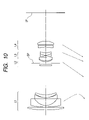
- FIG. 10 is a lens sectional view showing a zoom lens at wide angle end, according to Numerical Embodiment 4.
- FIG. 11 is an aberration graph of the zoom lens at wide angle end, according to Numerical Embodiment 4.
- FIG. 12 is an aberration graph of the zoom lens at telephoto end, according to Numerical Embodiment 4.
- FIG. 13 is a lens sectional view showing a zoom lens at wide angle end, according to Numerical Embodiment 5;
- FIG. 14 is an aberration graph of the zoom lens at wide angle end, according to Numerical Embodiment 5;
- FIG. 15 is an aberration graph of the zoom lens at telephoto end, according to Numerical Embodiment 5.
- FIG. 16 is a main part schematic view showing a single-lens reflex camera.
- FIGS. 1 , 4 , 7 , 10 , and 13 are lens sectional views showing a zoom lens at a wide angle end, according to Numerical Embodiments 1 to 5 (hereinafter collectively called “this embodiment”) described later, respectively.
- FIGS. 2 and 3 are various aberration graphs of the zoom lens at wide angle end and telephoto end according to Numerical Embodiment 1.
- FIGS. 5 and 6 are various aberration graphs of the zoom lens at wide angle end and telephoto end according to Numerical Embodiment 2.
- FIGS. 8 and 9 are various aberration graphs of the zoom lens at wide angle end and telephoto end according to Numerical Embodiment 3.
- FIGS. 1 , 4 , 7 , 10 , and 13 are lens sectional views showing a zoom lens at a wide angle end, according to Numerical Embodiments 1 to 5 (hereinafter collectively called “this embodiment”) described later, respectively.
- FIGS. 2 and 3 are various aberration graphs of the zoom
- FIGS. 11 and 12 are various aberration graphs of the zoom lens at wide angle end and telephoto end according to Numerical Embodiment 4.
- FIGS. 14 and 15 are various aberration graphs of the zoom lens at wide angle end and telephoto end, according to Numerical Embodiment 5.
- the zoom lens according to this embodiment is an image pickup lens system used for an image pickup device such as a single-lens reflex camera, or the like.
- the left is an object side (front) and the right is an image side (rear).
- L 2 denotes a second lens unit having a positive refractive power
- L 3 denotes a third lens unit having a negative refractive power
- L 4 denotes a fourth lens unit having a positive refractive power.
- Reference SP denotes an aperture stop, which is disposed in the second lens unit L 2 .
- Reference IP denotes an image plane where a photosensitive surface of a silver halide film or a solid-state image pickup element (photoelectric transducer) such as a CCD sensor or a CMOS sensor is disposed.
- the respective lens units are moved for zooming from wide angle end to telephoto end, so as to reduce an axial interval between the first lens unit L 1 and the second lens unit L 2 , to increase an axial interval between the second lens unit L 2 and the third lens unit L 3 , and to reduce an axial interval between the third lens unit L 3 and the fourth lens unit L 4 .
- the second lens unit L 2 , the third lens unit L 3 , and the fourth lens unit L 4 are moved for magnification toward the object side.
- the first lens unit L 1 is moved along a locus which is convex to the image side, thereby compensating a variation in image plane, which is caused by the magnification.
- the second lens unit L 2 and the fourth lens unit L 4 are integrally moved during zooming without change in those relative positions (axial interval therebetween), thereby simplifying a moving mechanism.
- Focusing on from an object at infinity to an object at a close point is performed by moving the first lens unit L 1 toward the object side.
- the focusing using the first lens unit L 1 is preferable because the amount of operation according to an object distance is kept substantially constant in a range from the wide angle end to the telephoto end, thereby simplifying the moving mechanism.
- the second lens unit L 2 is unsuitable as a focusing unit because paraxial lateral magnification becomes equal magnification during zooming.
- the third lens unit L 3 or the fourth lens unit L 4 is used as the focusing unit, when an interval between the respective lens units is widened to ensure the amount of movement, a size of the lens system increases. And it is not preferable because the number of lenses increases in order to suppress a variation in aberration during focusing.
- a back focus in axial distance between a surface vertex of a final lens surface and a paraxial image plane
- a refractive power arrangement in which an image side principal point is located closer to the image side at wide angle end.
- a so-called retrofocus (inverted telephoto) type in which a negative refractive power component is located on the object side and a positive refractive power component is located on the image side, may be used.
- the second lens unit L 2 , the third lens unit L 3 , and the fourth lens unit L 4 in which a composite refractive power is positive, are arranged apart from the first lens unit L 1 having the negative refractive power at the wide angle end.
- the third lens unit L 3 having the negative refractive power is located as close as possible to the object side in the partial system so as to locate the image side principal point closer to the image side.
- the respective lens units be arranged at the telephoto end so as to locate the image side principal point closer to the object side.
- a so-called telephoto type in which a positive refractive power component is located on the object side and a negative refractive power component is located on the image side, may be used.
- the first lens unit L 1 and the second lens unit L 2 are made close to each other to compose a partial system having a positive composite refractive power and the third lens unit L 3 and the fourth lens unit L 4 are made close to each other to compose a partial system having a negative composite refractive power.
- One of the features of the zoom lens disclosed in this embodiment is that the following conditional expressions (1) and (2) are simultaneously satisfied. Therefore, a desirable back focus is ensured with a state in which a suitable balance is achieved between optical performance and a zoom ratio in the zoom lens composed of the four units.
- fw a focal length of the entire system at the wide angle end
- the conditional expression (1) relates to a ratio between the focal length of the entire system at the wide angle end and the focal length of the entire system at the telephoto end.
- the conditional expression (1) specifies a zoom ratio (magnification ratio) best suitable for the structure of the zoom lens of the present invention.
- the zoom ratio becomes smaller than a lower limit value in the conditional expression (1), the zoom ratio can be realized even in the case of the zoom lens composed of two units. Therefore, it is useless to construct the zoom lens using the four lens units (advantage obtained from the four-unit structure cannot be improved).
- the upper limit value is more preferably set to 3.5.
- conditional expression (2) relates to a ratio between the maximum image height and the back focus at the wide angle end, and is used to sufficiently ensure a desirable back focus.
- the ratio becomes smaller than a lower limit value in the conditional expression (2), the back focus becomes shorter for the maximum image height. Therefore, the ratio is not suitable for an optical device that requires a predetermined back focus such as an image pickup lens for a single-lens reflex digital camera. Further, because an exit pupil position becomes closer to an image, the ratio is not suitable for a camera using a solid-state image pickup element that requires telecentricity to the image side.
- the zoom ratio exceeds an upper limit value in the conditional expression (2), the entire lens length at the wide angle end lengthens and the effective diameter of the first lens unit L 1 increases, so that the lens system becomes unbalanced. In addition, it is hard to correct the coma aberration and the distortion occurring in the first lens unit L 1 . Although the coma aberration and the distortion can be corrected using an aspherical lens, an increase in cost occurs.
- the upper limit value is more preferably set to 2.8.
- Another feature of the zoom lens disclosed in this embodiment is to satisfy the following conditional expression (3) instead of the conditional expression (2), together with the conditional expression (1). Therefore, a small size zoom lens is realized in which a suitable balance is achieved between the optical performance and the zoom ratio in the zoom lens composed of the four units. 2.5 ⁇ ft/fw ⁇ 4.0 (1) 4.1 ⁇ TDw/fw ⁇ 5.0 (3) where
- fw a focal length of the entire system at the wide angle end
- TDw axial distance between a lens surface closest to the object side (first lens surface) and a lens surface closest to the image side (final lens surface) at the wide angle end
- conditional expression (1) is as described above.
- the conditional expression (3) relates to a ratio between a distance between the lens surface closest to the object side (object side surface of the lens closest to the object side) and the lens surface closest to the image side (image side surface of the lens closest to the image side) at the wide angle end and the focal length of the entire system at the wide angle end.
- the ratio is mainly used to achieve a balance between a reduction in size and the performance.
- the ratio becomes smaller than a lower limit value in the conditional expression (3) to shorten the entire lens length at the wide angle end, the refractive power of each of the lens units becomes so strong that it is hard to correct the respective aberrations.
- the ratio exceeds an upper limit value in the conditional expression (3), the entire lens lengthens and a lens effective diameter (in particular, the effective diameter of the first lens unit L 1 ) increases.
- the upper limit value is more preferably set to 4.9.
- the zoom lens according to this embodiment discloses an arrangement in which the conditional expressions (1) to (3) are simultaneously satisfied.
- the zoom lens according to this embodiment satisfies the following conditions (A) to (D). Satisfying the conditions provides the effects described above.
- the first lens unit L 1 has a positive lens closest to the object side.
- the zoom lens according to this embodiment is a lens having a back focus relatively longer for the maximum image height, so that the lens effective diameter of the first lens unit L 1 can easily increase. Note that, at the wide angle end, it is hard to simultaneously correct the distortion and the coma aberration which are caused by the negative refractive power of the first lens unit L 1 . Therefore, the positive lens is located closest to the object side in the first lens unit L 1 and the distortion is actively corrected using the positive lens, thereby correcting total distortion and the coma aberration in the first lens unit L 1 .
- the conditional expression (4) relates to a ratio between the curvature radius of the object side lens surface of the positive lens and the curvature radius of the image side lens surface thereof, and is mainly used to achieve a balance between the distortion and a reduction in size.
- the ratio becomes smaller than a lower limit value in the conditional expression (4), it is not preferable that, in particular, astigmatism at the wide angle end increases and the lens diameter lengthens.
- an upper limit value in the conditional expression (4) an effect of the distortion on the image side lens surface of the positive lens reduces. Therefore, it is not preferable that the correction of the distortion at the wide angle end becomes insufficient.
- the lower limit value in the conditional expression (4) it is more preferable to set to ⁇ 0.1.
- the upper limit value is more preferably set to 0.15.
- the conditional expression (5) relates to a ratio between the focal length of the first lens unit L 1 used as the focusing unit and the focal length of the entire system at the telephoto end, and is mainly used to reduce the size of the zoom lens.
- the ratio becomes smaller than a lower limit value in the conditional expression (5) and thus the refractive power of the first lens unit L 1 becomes too strong, the distortion occurring in the first lens unit L 1 increases. Thus, it is not preferable that it is hard to correct the distortion by the subsequent units.
- the ratio exceeds an upper limit value in the conditional expression (5) and thus the refractive power of the first lens unit L 1 becomes too weak, the amount of operation of the first lens unit L 1 increases at focusing on a nearest object.
- the entire optical length at the wide angle end length ens to increase the lens effective diameter of the first lens unit L 1 .
- the lower limit value in the conditional expression (5) it is more preferable to set to 0.19.
- the upper limit value is more preferably set to 0.4.
- the second lens unit L 2 includes a first lens sub-unit having a positive refractive power, the aperture stop SP, and a second lens sub-unit having a positive refractive power, which are disposed in order from the object side to the image side. Following conditions 0.01 ⁇ Lp/TD 2 ⁇ 0.5 (6) 0.2 ⁇ f 2 /f 2 a ⁇ 0.6 (7) are satisfied, where Lp represents an axial distance between a lens surface of the first lens sub-unit closest to the image side and the aperture stop SP, TD 2 represents a thickness of the second lens unit L 2 , f 2 represents a focal length of the second lens unit L 2 , and f 2 a represents a focal length of the first lens sub-unit.
- the entrance pupil is located closer to the object side. Therefore, it is preferable in view of reducing the lens diameter of the first lens unit L 1 .
- the aperture stop SP is disposed on the object side of the second lens unit L 2 , it is necessary to provide a large distance between the first lens unit L 1 and the second lens unit L 2 so as not to interfere with each other in the case where the first lens unit L 1 and the second lens unit L 2 are close to each other at the telephoto end.
- the lens diameter of the first lens unit L 1 increases, with the result that the size of the zoom lens unit cannot be reduced.
- the second lens unit L 2 should be disposed closer to the object side.
- the first lens unit L 1 having the negative refractive power is separated from the second to fourth lens units L 2 to L 4 having the positive composite refractive power to produce the retrofocus type, thereby ensuring a sufficient back focus.
- the aperture stop SP is provided in the second lens unit L 2 to realize a reduction in size of the zoom lens unit.
- conditional expressions (6) and (7) are simultaneously satisfied.
- conditional expression (6) specifies a location of the aperture stop SP in the second lens unit L 2 and is used to reduce the size of the zoom lens system and to improve the performance thereof.
- the aperture stop SP and the first lens sub-unit may mechanically interfere with each other.
- the aperture stop SP is disposed on the object side, a variation in F number upon zooming becomes larger.
- Lp/TD 2 exceeds an upper limit value in the conditional expression (6) to dispose the aperture stop SP on the image side, the entrance pupil becomes close to the image side. Therefore, in particular, the lens diameter of the first lens unit L 1 increases, so that it is hard to correct the distortion. It is not preferable.
- the upper limit in the conditional expression (6) is more preferably set to 0.35.
- the conditional expression (7) relates to a ratio between the focal length of the second lens unit. L 2 and the focal length of the first lens sub-unit, specifies a refractive power arrangement of the second lens unit L 2 , and is used for in particular, the improvement of the performance of the zoom lens system-and the reduction in size thereof.
- the second lens unit L 2 When the second lens unit L 2 is located closer to the image side in order to ensure the desirable back focus, it becomes difficult to secure the sufficient amount of movement of the third lens unit L 3 relative to the second lens unit L 2 upon zooming, thereby reducing an aberration correction effect of the zoom type composed of the four units. It is not preferable. Note that it is more preferable to set the lower limit value in the conditional expression (7) to 0.3. The upper limit value is more preferably set to 0.5.
- the conditional expression (8) relates to a ratio between the focal length of the first lens unit L 1 and the focal length of the fourth lens unit L 4 , and is appropriately to set a refractive power arrangement, reduce the size of the zoom lens system while ensuring a back focus.
- the lens effective diameter of the first lens unit L 1 enlarges.
- the ratio becomes larger than an upper limit value in the conditional expression (8) and thus the refractive power of the first lens unit L 1 becomes too strong it is not preferable that it is hard to correct the distortion, and to ensure a desirable back focus particularly at the wide angle end.
- the lower limit value in the conditional expression (8) it is more preferable to set the lower limit value in the conditional expression (8) to ⁇ 0.70.
- the upper limit value is more preferably set to ⁇ 0.4.
- i denotes an order of an optical surface from the object side
- R 1 denotes a curvature radius of an i-th optical surface (i-th surface)
- Di denotes an interval between the i-th surface and an (i+1)-th surface
- Ni and ⁇ i denote a refractive index and an Abbe number of a material of an i-th optical member based on a d-line, respectively.
- f denotes a focal length
- Fno denotes an F number
- ⁇ denotes a half field angle.
- an aspherical shape is expressed by the following expression
- R represents a paraxial curvature radius
- A, B, C, D, E, and F represent aspherical coefficients. Note that “e-XX” in each of the aspherical coefficients indicates “ ⁇ 10 ⁇ XX ”.
- Table 1 shows correspondences between the conditional expressions and numeral values in the respective numerical embodiments.
- a zoom lens system can be realized in which the entire lens system has a small size, high optical performance is obtained, the number of lenses is small, and a structure is simple.
- a zoom lens can be realized in which a reduction in optical performance resulting from a manufacturing error such as a displacement in axis of each lens is small.
- FIG. 16 is a main part schematic view showing a single-lens reflex camera.
- reference numeral 10 denotes an image pickup lens having a zoom lens 1 according to Numerical Embodiments 1 to 5 of the present invention.
- the zoom lens 1 is held in a lens barrel 2 serving as a holding member.
- a camera main body 20 includes: a quick return mirror 3 for reflecting a light flux from the image pickup lens 10 upward; a focal plate 4 disposed at an image forming position of the image pickup lens 10 ; a pentagonal roof prism 5 for converting an reverse image formed on the focal plate 4 into an erect image; and an eyepiece lens 6 for observing the erect image.
- Reference numeral 7 denotes a film surface. In image pickup, the quick return mirror 3 is removed from an optical axis and an image is formed on the film surface 7 by the image pickup lens 10 .
- the zoom lens system of the present invention is suitable for an interchangeable lens for the single-lens reflex camera as shown in FIG. 16 .
Landscapes
- Physics & Mathematics (AREA)
- General Physics & Mathematics (AREA)
- Optics & Photonics (AREA)
- Nonlinear Science (AREA)
- Lenses (AREA)
Priority Applications (1)
| Application Number | Priority Date | Filing Date | Title |
|---|---|---|---|
| US11/438,126 US7196852B2 (en) | 2003-09-19 | 2006-05-18 | Zoom lens system and image pickup device having zoom lens system |
Applications Claiming Priority (2)
| Application Number | Priority Date | Filing Date | Title |
|---|---|---|---|
| JP2003-328074 | 2003-09-19 | ||
| JP2003328074A JP4289958B2 (ja) | 2003-09-19 | 2003-09-19 | ズームレンズ及びそれを有する撮像装置 |
Related Child Applications (1)
| Application Number | Title | Priority Date | Filing Date |
|---|---|---|---|
| US11/438,126 Continuation US7196852B2 (en) | 2003-09-19 | 2006-05-18 | Zoom lens system and image pickup device having zoom lens system |
Publications (2)
| Publication Number | Publication Date |
|---|---|
| US20050063069A1 US20050063069A1 (en) | 2005-03-24 |
| US7102829B2 true US7102829B2 (en) | 2006-09-05 |
Family
ID=34308805
Family Applications (2)
| Application Number | Title | Priority Date | Filing Date |
|---|---|---|---|
| US10/942,636 Expired - Lifetime US7102829B2 (en) | 2003-09-19 | 2004-09-16 | Zoom lens system and image pickup device having zoom lens system |
| US11/438,126 Expired - Fee Related US7196852B2 (en) | 2003-09-19 | 2006-05-18 | Zoom lens system and image pickup device having zoom lens system |
Family Applications After (1)
| Application Number | Title | Priority Date | Filing Date |
|---|---|---|---|
| US11/438,126 Expired - Fee Related US7196852B2 (en) | 2003-09-19 | 2006-05-18 | Zoom lens system and image pickup device having zoom lens system |
Country Status (2)
| Country | Link |
|---|---|
| US (2) | US7102829B2 (enExample) |
| JP (1) | JP4289958B2 (enExample) |
Cited By (6)
| Publication number | Priority date | Publication date | Assignee | Title |
|---|---|---|---|---|
| US20080002263A1 (en) * | 2006-06-22 | 2008-01-03 | Hiroshi Yamamoto | Zoom lens system, imaging apparatus and method for varying focal length |
| US20090002844A1 (en) * | 2007-06-29 | 2009-01-01 | Nikon Corporation | Zoom lens system, optical apparatus, and method for zooming |
| US20090002841A1 (en) * | 2007-06-29 | 2009-01-01 | Nikon Corporation | Zoom lens system, optical apparatus, and method for zooming |
| US20090034100A1 (en) * | 2007-07-24 | 2009-02-05 | Nikon Corporation | Optical system, imaging apparatus, and method for forming image by the optical system |
| US20090231708A1 (en) * | 2006-07-21 | 2009-09-17 | Satoru Shibata | Zoom lens system, imaging apparatus, and method for zooming the zoom lens system |
| US20130215320A1 (en) * | 2012-02-21 | 2013-08-22 | Yoshihito Souma | Zoom Lens System, Imaging Optical Device, and Digital Appliance |
Families Citing this family (15)
| Publication number | Priority date | Publication date | Assignee | Title |
|---|---|---|---|---|
| JP4612485B2 (ja) * | 2005-06-29 | 2011-01-12 | Hoya株式会社 | 広角ズームレンズ系 |
| JP4834360B2 (ja) * | 2005-09-12 | 2011-12-14 | キヤノン株式会社 | ズームレンズ及びそれを有する撮像装置 |
| JP5028776B2 (ja) * | 2005-09-28 | 2012-09-19 | 株式会社ニコン | ズームレンズ |
| JP5105837B2 (ja) * | 2006-11-22 | 2012-12-26 | オリンパス株式会社 | ズーム光学系、及びそれを有する電子撮像装置 |
| JP2008145967A (ja) * | 2006-12-13 | 2008-06-26 | Sony Corp | ズームレンズ及び撮像装置 |
| TW200925643A (en) * | 2007-12-04 | 2009-06-16 | Ind Tech Res Inst | Optical lens module |
| JP5465000B2 (ja) * | 2009-12-25 | 2014-04-09 | キヤノン株式会社 | ズームレンズ及びそれを有する撮像装置 |
| JP5084888B2 (ja) * | 2010-09-10 | 2012-11-28 | ペンタックスリコーイメージング株式会社 | 広角ズームレンズ系 |
| WO2012086154A1 (ja) | 2010-12-22 | 2012-06-28 | パナソニック株式会社 | ズームレンズ系、交換レンズ装置及びカメラシステム |
| US9250422B2 (en) * | 2012-03-25 | 2016-02-02 | Iain A. Neil | Zoom lens with forward-located aperture stop |
| JP2013242502A (ja) * | 2012-05-23 | 2013-12-05 | Sony Corp | ズームレンズおよび撮像装置 |
| JP6256732B2 (ja) * | 2012-08-30 | 2018-01-10 | 株式会社ニコン | 変倍光学系、及び、この変倍光学系を有する光学装置 |
| JP6355076B2 (ja) * | 2013-10-07 | 2018-07-11 | パナソニックIpマネジメント株式会社 | ズームレンズ系、交換レンズ装置及びカメラシステム |
| JP6415142B2 (ja) * | 2014-07-08 | 2018-10-31 | キヤノン株式会社 | 光学系及びそれを有する光学機器 |
| US11143851B2 (en) * | 2017-04-05 | 2021-10-12 | Nikon Corporation | Variable magnification optical system, optical apparatus, and method for producing variable magnification optical system |
Citations (23)
| Publication number | Priority date | Publication date | Assignee | Title |
|---|---|---|---|---|
| JPS5711315A (en) | 1980-06-24 | 1982-01-21 | Konishiroku Photo Ind Co Ltd | Zoom lens with highly variable magnification preceding negative groups |
| JPS5895315A (ja) | 1981-11-30 | 1983-06-06 | Minolta Camera Co Ltd | 広角域を含む高変倍率ズ−ムレンズ系 |
| JPS59229517A (ja) | 1983-06-13 | 1984-12-24 | Nippon Kogaku Kk <Nikon> | 4群構成ズ−ムレンズ |
| JPS6055313A (ja) | 1983-09-06 | 1985-03-30 | Asahi Optical Co Ltd | ズ−ムレンズ |
| JPS6087312A (ja) | 1983-10-20 | 1985-05-17 | Ricoh Co Ltd | 超広角高変倍ズ−ムレンズ |
| JPS6162013A (ja) | 1984-09-03 | 1986-03-29 | Nippon Kogaku Kk <Nikon> | ズ−ムレンズ |
| JPS61123811A (ja) | 1984-11-20 | 1986-06-11 | Nippon Kogaku Kk <Nikon> | ズ−ムレンズ |
| JPS6263909A (ja) | 1985-09-17 | 1987-03-20 | Nippon Kogaku Kk <Nikon> | ズ−ムレンズ |
| JPH02136812A (ja) | 1988-11-18 | 1990-05-25 | Canon Inc | リヤーフォーカス式のズームレンズ |
| JPH04163415A (ja) | 1990-10-26 | 1992-06-09 | Canon Inc | 広角ズームレンズ |
| JPH04235515A (ja) | 1991-01-11 | 1992-08-24 | Nikon Corp | 超広角ズームレンズ |
| JPH0519170A (ja) | 1991-02-15 | 1993-01-29 | Asahi Optical Co Ltd | ズームレンズ |
| US5264965A (en) | 1991-02-15 | 1993-11-23 | Asahi Kogaku Kogyo Kabushiki Kaisha | Zoom lens |
| JPH05313065A (ja) | 1992-05-11 | 1993-11-26 | Canon Inc | ズームレンズ |
| JPH0682698A (ja) | 1992-09-02 | 1994-03-25 | Minolta Camera Co Ltd | 大口径広角ズームレンズ |
| JPH07287168A (ja) | 1994-04-19 | 1995-10-31 | Nikon Corp | 高変倍率ズームレンズ |
| US5585970A (en) | 1994-04-19 | 1996-12-17 | Nikon Corporation | Zoom lens with high zoom ratio |
| US5663835A (en) | 1994-07-29 | 1997-09-02 | Nikon Corporation | Inner focus zoom lens |
| US5835272A (en) * | 1996-07-24 | 1998-11-10 | Nikon Corporation | Zoom Lens |
| JP2000338397A (ja) | 1999-05-26 | 2000-12-08 | Canon Inc | ズームレンズ |
| US6320698B1 (en) | 1993-11-29 | 2001-11-20 | Nikon Corporation | Zoom lens with vibration reduction function |
| US6639721B2 (en) * | 2001-02-19 | 2003-10-28 | Canon Kabushiki Kaisha | Zoom lens system and optical apparatus using the same |
| US6809880B2 (en) * | 2001-10-29 | 2004-10-26 | Pentax Corporation | Zoom lens system |
Family Cites Families (1)
| Publication number | Priority date | Publication date | Assignee | Title |
|---|---|---|---|---|
| US5999329A (en) * | 1995-12-26 | 1999-12-07 | Nikon Corporation | Variable focal length optical system |
-
2003
- 2003-09-19 JP JP2003328074A patent/JP4289958B2/ja not_active Expired - Lifetime
-
2004
- 2004-09-16 US US10/942,636 patent/US7102829B2/en not_active Expired - Lifetime
-
2006
- 2006-05-18 US US11/438,126 patent/US7196852B2/en not_active Expired - Fee Related
Patent Citations (26)
| Publication number | Priority date | Publication date | Assignee | Title |
|---|---|---|---|---|
| JPS5711315A (en) | 1980-06-24 | 1982-01-21 | Konishiroku Photo Ind Co Ltd | Zoom lens with highly variable magnification preceding negative groups |
| JPS5895315A (ja) | 1981-11-30 | 1983-06-06 | Minolta Camera Co Ltd | 広角域を含む高変倍率ズ−ムレンズ系 |
| JPS59229517A (ja) | 1983-06-13 | 1984-12-24 | Nippon Kogaku Kk <Nikon> | 4群構成ズ−ムレンズ |
| JPS6055313A (ja) | 1983-09-06 | 1985-03-30 | Asahi Optical Co Ltd | ズ−ムレンズ |
| JPS6087312A (ja) | 1983-10-20 | 1985-05-17 | Ricoh Co Ltd | 超広角高変倍ズ−ムレンズ |
| JPS6162013A (ja) | 1984-09-03 | 1986-03-29 | Nippon Kogaku Kk <Nikon> | ズ−ムレンズ |
| JPS61123811A (ja) | 1984-11-20 | 1986-06-11 | Nippon Kogaku Kk <Nikon> | ズ−ムレンズ |
| JPS6263909A (ja) | 1985-09-17 | 1987-03-20 | Nippon Kogaku Kk <Nikon> | ズ−ムレンズ |
| JP2629904B2 (ja) | 1988-11-18 | 1997-07-16 | キヤノン株式会社 | リヤーフォーカス式のズームレンズ |
| JPH02136812A (ja) | 1988-11-18 | 1990-05-25 | Canon Inc | リヤーフォーカス式のズームレンズ |
| US5132848A (en) | 1990-10-26 | 1992-07-21 | Canon Kabushiki Kaisha | Wideangle four group zoom lens |
| JPH04163415A (ja) | 1990-10-26 | 1992-06-09 | Canon Inc | 広角ズームレンズ |
| JPH04235515A (ja) | 1991-01-11 | 1992-08-24 | Nikon Corp | 超広角ズームレンズ |
| JPH0519170A (ja) | 1991-02-15 | 1993-01-29 | Asahi Optical Co Ltd | ズームレンズ |
| US5264965A (en) | 1991-02-15 | 1993-11-23 | Asahi Kogaku Kogyo Kabushiki Kaisha | Zoom lens |
| JPH05313065A (ja) | 1992-05-11 | 1993-11-26 | Canon Inc | ズームレンズ |
| JPH0682698A (ja) | 1992-09-02 | 1994-03-25 | Minolta Camera Co Ltd | 大口径広角ズームレンズ |
| US6320698B1 (en) | 1993-11-29 | 2001-11-20 | Nikon Corporation | Zoom lens with vibration reduction function |
| US5585970A (en) | 1994-04-19 | 1996-12-17 | Nikon Corporation | Zoom lens with high zoom ratio |
| JPH07287168A (ja) | 1994-04-19 | 1995-10-31 | Nikon Corp | 高変倍率ズームレンズ |
| US5663835A (en) | 1994-07-29 | 1997-09-02 | Nikon Corporation | Inner focus zoom lens |
| US5835272A (en) * | 1996-07-24 | 1998-11-10 | Nikon Corporation | Zoom Lens |
| JP2000338397A (ja) | 1999-05-26 | 2000-12-08 | Canon Inc | ズームレンズ |
| US6710931B1 (en) | 1999-05-26 | 2004-03-23 | Canon Kabushiki Kaisha | Zoom lens, and image pickup apparatus and image projection apparatus using the same |
| US6639721B2 (en) * | 2001-02-19 | 2003-10-28 | Canon Kabushiki Kaisha | Zoom lens system and optical apparatus using the same |
| US6809880B2 (en) * | 2001-10-29 | 2004-10-26 | Pentax Corporation | Zoom lens system |
Cited By (13)
| Publication number | Priority date | Publication date | Assignee | Title |
|---|---|---|---|---|
| US20080002263A1 (en) * | 2006-06-22 | 2008-01-03 | Hiroshi Yamamoto | Zoom lens system, imaging apparatus and method for varying focal length |
| US7599123B2 (en) | 2006-06-22 | 2009-10-06 | Nikon Corporation | Zoom lens system, imaging apparatus and method for varying focal length |
| US20090231708A1 (en) * | 2006-07-21 | 2009-09-17 | Satoru Shibata | Zoom lens system, imaging apparatus, and method for zooming the zoom lens system |
| US10437026B2 (en) | 2006-07-21 | 2019-10-08 | Nikon Corporation | Zoom lens system, imaging apparatus, and method for zooming the zoom lens system |
| US20110194191A1 (en) * | 2006-07-21 | 2011-08-11 | Nikon Corporation | Zoom lens system, imaging apparatus, and method for zooming the zoom lens system |
| US8144403B2 (en) | 2007-06-29 | 2012-03-27 | Nikon Corporation | Zoom lens system, optical apparatus, and method for zooming |
| US20090002844A1 (en) * | 2007-06-29 | 2009-01-01 | Nikon Corporation | Zoom lens system, optical apparatus, and method for zooming |
| US20090002841A1 (en) * | 2007-06-29 | 2009-01-01 | Nikon Corporation | Zoom lens system, optical apparatus, and method for zooming |
| US7961409B2 (en) | 2007-06-29 | 2011-06-14 | Nikon Corporation | Zoom lens system, optical apparatus, and method for zooming |
| US20090034100A1 (en) * | 2007-07-24 | 2009-02-05 | Nikon Corporation | Optical system, imaging apparatus, and method for forming image by the optical system |
| US7920341B2 (en) | 2007-07-24 | 2011-04-05 | Nikon Corporation | Optical system, imaging apparatus, and method for forming image by the optical system |
| US20130215320A1 (en) * | 2012-02-21 | 2013-08-22 | Yoshihito Souma | Zoom Lens System, Imaging Optical Device, and Digital Appliance |
| US8786956B2 (en) * | 2012-02-21 | 2014-07-22 | Konica Minolta Advanced Layers, Inc. | Zoom lens system, imaging optical device, and digital appliance |
Also Published As
| Publication number | Publication date |
|---|---|
| US20050063069A1 (en) | 2005-03-24 |
| US7196852B2 (en) | 2007-03-27 |
| US20060209425A1 (en) | 2006-09-21 |
| JP4289958B2 (ja) | 2009-07-01 |
| JP2005092056A (ja) | 2005-04-07 |
Similar Documents
| Publication | Publication Date | Title |
|---|---|---|
| US7023625B2 (en) | Zoom lens and optical apparatus having the same | |
| US7187504B2 (en) | Zoom lens and image pick up apparatus including the same | |
| US7443600B2 (en) | Zoom lens and image pickup apparatus having the same | |
| US7102829B2 (en) | Zoom lens system and image pickup device having zoom lens system | |
| US7961409B2 (en) | Zoom lens system, optical apparatus, and method for zooming | |
| US7428107B2 (en) | Zoom lens and image pickup apparatus having the same | |
| US8144403B2 (en) | Zoom lens system, optical apparatus, and method for zooming | |
| US7268811B2 (en) | Zoom lens system | |
| US20080273250A1 (en) | Imaging apparatus | |
| US20020154908A1 (en) | Zoom lens and optical apparatus using the same | |
| US20090244724A1 (en) | Optical system, method for focusing, and imaging apparatus equipped therewith | |
| US6972909B2 (en) | Zoom lens and image pickup apparatus having the same | |
| US7408720B2 (en) | Zoom lens and image pickup apparatus having same | |
| US20090190235A1 (en) | Zoom lens and image pickup apparatus including the same | |
| US20030123157A1 (en) | Zoom lens and camera having the zoom lens | |
| US7019911B2 (en) | Zoom lens system and image pickup apparatus having the same | |
| US7075730B2 (en) | Zoom lens system and image pickup apparatus including the same | |
| JPH07113955A (ja) | ズームレンズ | |
| JPH11295599A (ja) | 広角系ズームレンズ | |
| JPH04212916A (ja) | 像振れ補正機能を有する変倍光学系 |
Legal Events
| Date | Code | Title | Description |
|---|---|---|---|
| AS | Assignment |
Owner name: CANON KABUSHIKI KAISHA, JAPAN Free format text: ASSIGNMENT OF ASSIGNORS INTEREST;ASSIGNOR:NISHIMURA, TAKESHI;REEL/FRAME:015811/0043 Effective date: 20040906 |
|
| STCF | Information on status: patent grant |
Free format text: PATENTED CASE |
|
| CC | Certificate of correction | ||
| FEPP | Fee payment procedure |
Free format text: PAYOR NUMBER ASSIGNED (ORIGINAL EVENT CODE: ASPN); ENTITY STATUS OF PATENT OWNER: LARGE ENTITY |
|
| FPAY | Fee payment |
Year of fee payment: 4 |
|
| FPAY | Fee payment |
Year of fee payment: 8 |
|
| MAFP | Maintenance fee payment |
Free format text: PAYMENT OF MAINTENANCE FEE, 12TH YEAR, LARGE ENTITY (ORIGINAL EVENT CODE: M1553) Year of fee payment: 12 |