US7100671B2 - Method of manufacturing cylinder head - Google Patents
Method of manufacturing cylinder head Download PDFInfo
- Publication number
- US7100671B2 US7100671B2 US10/967,351 US96735104A US7100671B2 US 7100671 B2 US7100671 B2 US 7100671B2 US 96735104 A US96735104 A US 96735104A US 7100671 B2 US7100671 B2 US 7100671B2
- Authority
- US
- United States
- Prior art keywords
- core
- partition plate
- expansion
- intake
- distal end
- Prior art date
- Legal status (The legal status is an assumption and is not a legal conclusion. Google has not performed a legal analysis and makes no representation as to the accuracy of the status listed.)
- Expired - Fee Related
Links
- 238000004519 manufacturing process Methods 0.000 title claims abstract description 10
- 238000005192 partition Methods 0.000 claims abstract description 151
- 229910052751 metal Inorganic materials 0.000 claims abstract description 60
- 239000002184 metal Substances 0.000 claims abstract description 60
- 238000000465 moulding Methods 0.000 claims description 18
- 238000000034 method Methods 0.000 claims description 14
- 239000013013 elastic material Substances 0.000 claims description 7
- 239000004576 sand Substances 0.000 description 25
- 238000005266 casting Methods 0.000 description 12
- 239000000463 material Substances 0.000 description 8
- 230000015572 biosynthetic process Effects 0.000 description 7
- PPBRXRYQALVLMV-UHFFFAOYSA-N Styrene Chemical compound C=CC1=CC=CC=C1 PPBRXRYQALVLMV-UHFFFAOYSA-N 0.000 description 4
- 230000002411 adverse Effects 0.000 description 3
- 238000007664 blowing Methods 0.000 description 3
- 230000000717 retained effect Effects 0.000 description 3
- 239000000853 adhesive Substances 0.000 description 2
- 230000001070 adhesive effect Effects 0.000 description 2
- 230000008901 benefit Effects 0.000 description 2
- 238000002485 combustion reaction Methods 0.000 description 2
- 238000004512 die casting Methods 0.000 description 2
- 230000000694 effects Effects 0.000 description 2
- 239000006260 foam Substances 0.000 description 2
- 239000002737 fuel gas Substances 0.000 description 2
- 230000006872 improvement Effects 0.000 description 2
- 230000009467 reduction Effects 0.000 description 2
- 229910000838 Al alloy Inorganic materials 0.000 description 1
- 230000015556 catabolic process Effects 0.000 description 1
- 239000000919 ceramic Substances 0.000 description 1
- 230000002950 deficient Effects 0.000 description 1
- 230000006866 deterioration Effects 0.000 description 1
- 239000004744 fabric Substances 0.000 description 1
- 230000002349 favourable effect Effects 0.000 description 1
- 239000000446 fuel Substances 0.000 description 1
- 239000007789 gas Substances 0.000 description 1
- -1 i.e. Substances 0.000 description 1
- 238000012986 modification Methods 0.000 description 1
- 230000004048 modification Effects 0.000 description 1
- 230000002093 peripheral effect Effects 0.000 description 1
- 239000002984 plastic foam Substances 0.000 description 1
- 238000000926 separation method Methods 0.000 description 1
Images


Classifications
-
- F—MECHANICAL ENGINEERING; LIGHTING; HEATING; WEAPONS; BLASTING
- F02—COMBUSTION ENGINES; HOT-GAS OR COMBUSTION-PRODUCT ENGINE PLANTS
- F02F—CYLINDERS, PISTONS OR CASINGS, FOR COMBUSTION ENGINES; ARRANGEMENTS OF SEALINGS IN COMBUSTION ENGINES
- F02F1/00—Cylinders; Cylinder heads
- F02F1/24—Cylinder heads
- F02F1/42—Shape or arrangement of intake or exhaust channels in cylinder heads
- F02F1/4235—Shape or arrangement of intake or exhaust channels in cylinder heads of intake channels
- F02F1/4242—Shape or arrangement of intake or exhaust channels in cylinder heads of intake channels with a partition wall inside the channel
-
- B—PERFORMING OPERATIONS; TRANSPORTING
- B22—CASTING; POWDER METALLURGY
- B22C—FOUNDRY MOULDING
- B22C9/00—Moulds or cores; Moulding processes
- B22C9/10—Cores; Manufacture or installation of cores
-
- B—PERFORMING OPERATIONS; TRANSPORTING
- B22—CASTING; POWDER METALLURGY
- B22D—CASTING OF METALS; CASTING OF OTHER SUBSTANCES BY THE SAME PROCESSES OR DEVICES
- B22D19/00—Casting in, on, or around objects which form part of the product
- B22D19/0009—Cylinders, pistons
-
- F—MECHANICAL ENGINEERING; LIGHTING; HEATING; WEAPONS; BLASTING
- F02—COMBUSTION ENGINES; HOT-GAS OR COMBUSTION-PRODUCT ENGINE PLANTS
- F02B—INTERNAL-COMBUSTION PISTON ENGINES; COMBUSTION ENGINES IN GENERAL
- F02B31/00—Modifying induction systems for imparting a rotation to the charge in the cylinder
- F02B31/08—Modifying induction systems for imparting a rotation to the charge in the cylinder having multiple air inlets
- F02B31/085—Modifying induction systems for imparting a rotation to the charge in the cylinder having multiple air inlets having two inlet valves
-
- F—MECHANICAL ENGINEERING; LIGHTING; HEATING; WEAPONS; BLASTING
- F02—COMBUSTION ENGINES; HOT-GAS OR COMBUSTION-PRODUCT ENGINE PLANTS
- F02F—CYLINDERS, PISTONS OR CASINGS, FOR COMBUSTION ENGINES; ARRANGEMENTS OF SEALINGS IN COMBUSTION ENGINES
- F02F1/00—Cylinders; Cylinder heads
- F02F1/24—Cylinder heads
-
- F—MECHANICAL ENGINEERING; LIGHTING; HEATING; WEAPONS; BLASTING
- F02—COMBUSTION ENGINES; HOT-GAS OR COMBUSTION-PRODUCT ENGINE PLANTS
- F02B—INTERNAL-COMBUSTION PISTON ENGINES; COMBUSTION ENGINES IN GENERAL
- F02B2275/00—Other engines, components or details, not provided for in other groups of this subclass
- F02B2275/48—Tumble motion in gas movement in cylinder
-
- F—MECHANICAL ENGINEERING; LIGHTING; HEATING; WEAPONS; BLASTING
- F02—COMBUSTION ENGINES; HOT-GAS OR COMBUSTION-PRODUCT ENGINE PLANTS
- F02F—CYLINDERS, PISTONS OR CASINGS, FOR COMBUSTION ENGINES; ARRANGEMENTS OF SEALINGS IN COMBUSTION ENGINES
- F02F2200/00—Manufacturing
- F02F2200/06—Casting
-
- Y—GENERAL TAGGING OF NEW TECHNOLOGICAL DEVELOPMENTS; GENERAL TAGGING OF CROSS-SECTIONAL TECHNOLOGIES SPANNING OVER SEVERAL SECTIONS OF THE IPC; TECHNICAL SUBJECTS COVERED BY FORMER USPC CROSS-REFERENCE ART COLLECTIONS [XRACs] AND DIGESTS
- Y02—TECHNOLOGIES OR APPLICATIONS FOR MITIGATION OR ADAPTATION AGAINST CLIMATE CHANGE
- Y02T—CLIMATE CHANGE MITIGATION TECHNOLOGIES RELATED TO TRANSPORTATION
- Y02T10/00—Road transport of goods or passengers
- Y02T10/10—Internal combustion engine [ICE] based vehicles
- Y02T10/12—Improving ICE efficiencies
Definitions
- the present invention relates to a method of manufacturing a cylinder head and, more particularly, to a method of manufacturing a cylinder head with an intake port in which a partition plate is disposed.
- Japanese Patent Application Laid-Open Publication No. 2001-193469 disclose paragraphs 0011, 0020 and 0022 and FIGS. 1, 3 and 4) and Japanese Patent Application National Publication of Translated Version No. 2002-501829 (see paragraph 0022 and FIG. 3) disclose structures wherein an airflow control valve disposed in an intake-side distal end of an intake port is controlled while permitting a partition plate to deflect intake air, introduced from the intake port to a cylinder bore, for intensifying tumble flow occurring inside the cylinder bore to achieve improvement over fuel consumption.
- a side across which intake air, such as air and fuel gas, is passed is referred to as an “intake-side” and the opposite side, i.e., a cylinder bore side is referred to as a “cylinder-side”.
- examples of the partition plates include those which are integrally formed as partition walls that partition the intake ports, those which are formed in corrugated configurations to take countermeasures for the occurrence of deformation caused by thermal expansion during cast-in molding and those which have bosses or projections to allow the partition plates to reliably remain under a fixed condition during cast-in molding.
- the partition plates must be formed in a thinned wall structure not to increase resistance in flow of intake air passing across the intake ports of the cylinder heads and consideration should be taken into account for thermal affect resulting from molten metal.
- the partition wall which partitions the intake port
- the partition wall which partitions the intake port
- probabilities occur with an increase in resistance in flow of intake air.
- the partition plate formed in the corrugated configuration even though the partition plate is able to absorb the thermal expansion in a radial direction of the intake port, the thermal expansion in an axial direction of the intake port cannot be absorbed.
- the present invention has been completed upon such studies conducted by the present inventor and has an object to provide a method of manufacturing a cylinder head wherein even when a partition plate with a thinned wall is preliminarily set in a casting mold to allow the partition plate to be cast in with molten metal for cast molding, thermal affects resulting from molten metal can be minimized as less as possible for thereby performing smooth cast molding.
- one aspect of the present invention provides a method of manufacturing a cylinder head having a partition plate for an intake port, which comprises: preparing a partition plate having an intake-side distal end and a cylinder-side distal end; locating the partition plate in a core to form an intake port such that at least the intake-side distal end of the partition plate is located in an expansion-permit space that permits thermal expansion of the partition plate caused by heat of molten metal; supplying molten metal to a periphery of the partition plate; solidifying the molten metal; and removing the core.
- FIG. 1 is a schematic cross sectional view illustrating an engine cylinder head of a first embodiment according to the present invention
- FIG. 2 is a cross sectional view, taken on an orthogonal plane, of an intake port of the presently filed embodiment and corresponds to a cross section taken on line A—A of FIG. 1 ;
- FIG. 3 is a schematic view illustrating an airflow current condition in the cylinder head of the presently filed embodiment to show the structure, shown in FIG. 1 , more in detail;
- FIG. 4 is a schematic plan view of the cylinder head as viewed in a Z-direction in FIG. 3 ;
- FIG. 5 is a schematic cross sectional view illustrating a mold for molding a port core of the presently filed embodiment
- FIG. 6 is a schematic plan view illustrating the mold, for molding the port core of the presently filed embodiment, which is broken away to expose a partition plate;
- FIG. 7 is an enlarged view illustrating an essential part shown in FIG. 6 ;
- FIG. 8 is a schematic cross sectional view illustrating a condition under which the port core is set in a casting mold for cast molding the cylinder head of presently filed embodiment
- FIG. 10 is a schematic plan view illustrating how an expansion-permit space is formed using a loose piece of the presently filed embodiment
- FIG. 11 is a schematic cross sectional view taken on line C—C in FIG. 10 ;
- FIG. 13 is a schematic cross sectional view taken on line D—D in FIG. 12 ;
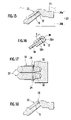
- FIG. 14 is a schematic plan view illustrating a structure wherein a plate member of a second embodiment according to the present invention is located at an end of a partition plate;
- FIG. 15 is a schematic cross sectional view taken on line E—E in FIG. 14 ;
- FIG. 17 is a schematic plan view illustrating a modified form of the structure wherein the plate member of the presently filed embodiment is located at the end of the partition plate;
- a first embodiment according to the present invention is described below.
- FIG. 1 is a schematic cross sectional view illustrating a cylinder head 1 , of an engine, of the presently filed embodiment
- FIG. 2 is a cross sectional view taken on an orthogonal plane of an intake port 4 of the cylinder head 1 and corresponds to a cross sectional view taken on line A—A in FIG. 1
- FIG. 3 is a schematic view illustrating a flow current condition in the cylinder head 1
- FIG. 4 is a schematic plan view of the cylinder head shown in FIG. 3 .
- the cylinder head 1 is set on a top of a cylinder block 2 and has the intake port 4 for introducing intake airflow, composed of air and fuel gas delivered from an intake manifold IN, into a cylinder bore 3 and an exhaust port 5 through which exhaust gases resulting from combustion in the cylinder bore 3 are exhausted.
- the engine intake and exhaust structure is of the type, including one cylinder with four vales, which has two intake valves 6 and two exhaust valves 7 .
- a partition plate 10 Disposed inside the intake port 4 is a partition plate 10 that extends along a direction (as shown by a series of whitened arrows FL in FIG. 3 ) in which intake air flows from an intake-side (an outer terminal side in FIG. 3 ) toward the cylinder-side.
- the intake port 4 has a passage, closer to the cylinder, which is largely curved, and with a cylinder-side distal end Ta of the partition plate 10 located at various incorrect positions, irregularities occur in characteristic of airflow current to remarkably and adversely affect a situation under which tumble flow is generated.
- the locating position of the cylinder-side distal end Ta forms an exceptionally important position.
- a position at which the intake-side distal end Tb of the partition plate 10 is located serves as a side at which intake air is divided and in which the control valve 11 is disposed.
- the intake-side distal end Tb of the partition plate 10 needs not be set to a position at a higher precision than that required for the position in which the cylinder-side distal end Ta is located.
- the presently filed embodiment is able to realize a structure wherein in cast molding the cylinder head 1 , the cylinder-side distal end Ta is set to a fixed location whereas the intake-side distal end Tb is made relatively free to assume various positions whereby even with the partition plate 10 suffers from thermal affects when pouring molten metal, the thermal affects can be absorbed at areas of the intake-side distal end Tb.
- FIG. 5 is a schematic cross sectional view illustrating a core forming mold (hereinafter referred to as a core mold) for molding a port core (hereinafter referred to as a core) of the presently filed embodiment
- FIG. 6 is a schematic plan view illustrating the core forming mold for molding the core of the presently filed embodiment with a portion thereof being cutaway to expose the partition plate
- FIG. 7 is an enlarged view of an essential part of FIG. 6
- FIG. 8 is a schematic cross sectional view illustrating a die-casting mold in which the core is set for die-casting the cylinder head of the presently filed embodiment
- FIG. 9 is a schematic cross sectional view taken on line B—B of FIG. 7 .
- a core 22 is molded using the core mold 20 as shown in FIG. 5 .
- the core mold 20 is comprised of a plurality of partial molds such as a core-forming upper mold 20 a and a core-forming lower mold 20 b and combining these partial molds internally forms a cavity 21 for molding the core into which mold sand is brown and compacted to form the core 22 .
- reference numeral 22 a designates a core print for the core 22 .
- partition plate 10 under a condition where the partition plate 10 is set in the core mold 20 , mold sand is compacted into the cavity 21 to form the core 22 as shown in FIG. 6 .
- the partition plate 10 is positioned in the core mold 20 in a way not to be displaced and set on a rest formed on a mold parting line of the core mold 20 . That is, the partition plate 10 is placed on a peripheral edge of the cavity 21 of the lower mold 20 b and, under such a condition, held in fixed place.
- the partition plate 10 has side protrusions 10 b slightly protruding from side edges 10 a , and cutouts 10 c formed in the intake-side distal end Tb at the side protrusions 10 b as shown in FIG. 7 more in detail.
- the side protrusions 10 b serve as areas that allow the partition plate 10 to be more reliably retained when the partition plate 10 is cast in with molten metal that will be described below.
- the cutouts 10 c serve as areas to permit mold sand to enter for thereby forming sand wall portions 24 .
- sand wall portions is meant the portions that are formed only with mold sand along the cutouts 10 c to allow the core 22 , which has a thinned wall thickness and is elongated, to extend and that serve as a sort of weirs to prevent the entry of molten metal, and detailed functions will be described later in detail.
- the core 22 is formed in the core mold 20 shown in FIG. 5 and taken out by separating the partial molds, such as the core-forming upper mold 20 a and the core-forming lower mold 20 b , in a separating direction as shown by an arrow S 1 in FIG. 5 .
- the casting mold 25 is comprised of an upper mold 25 a , a lower mold 25 b and side molds 25 c , and with the core 22 supported between the lower mold 25 b and the side molds 25 c and covered with the upper mold 25 a , a cavity 26 is defined to form the cylinder head 1 .
- reference numeral 23 designates cores for water jackets.
- pouring molten metal such as aluminum alloy
- a pouring gate (not shown) forms the cylinder head 1 as shown in FIG. 1 and during pouring molten metal, thermal expansion occurs in the partition plate 10 , set in the core 22 , due to heat developed by molten metal.
- expansion-permit spaces 30 are formed in the core 22 at the intake-side distal end Tb of the partition plate 10 disposed in the core 22 .
- the expansion-permit spaces 30 serve as areas to avoid the occurrence of damages or cracks to the core 22 even in the presence of pressures, resulting from thermal expansion, acting on the partition plate 10 due to heat of molten metal.
- no shapes of or no positions of the expansion-permit space 30 are major concerns as far as the expansion-permit spaces 30 have a function to permit the thermal expansion of the partition plate 10 and those shown in FIGS. 5 to 9 are formed in the core 22 at the intake-side distal end Tb of the partition plate 10 disposed in the core 22 .
- Such expansion-permit spaces 30 are formed by removing mold sand from vicinities of the intake-side distal end Tb of the partition plate 10 when forming the core 22 .
- the expansion-permit spaces 30 are determined to be scaled to the extent, as shown in FIG. 9 , such that a thickness (a length in a y-direction) is set to be greater than a plate thickness t of the partition plate 10 and a length L between the intake-side distal end Tb of the partition plate 10 and a bottom of the space 30 is set to a value to absorb the elongation of the partition plate 10 in a lengthwise direction (in an x-direction) caused by thermal expansion due to heat of molten metal.
- the partition plate 10 thermally expands due to heat of molten metal and such thermal expansion collectively occurs on the intake-side distal end Tb that is apt to expand in the expansion-permit space 30 , i.e., the intake-side distal end Tb of the partition plate 10 merely slides (expands) in the x-direction.
- the intake-side distal end Tb of the partition plate 10 merely slides (expands) in the x-direction.
- no pressure is applied to the core 22 toward the intake-side distal end Tb of the partition plate 10 and no cracks or damages occur to the core 22 per se.
- both ends of the expansion-permit spaces 30 remain under a condition substantially covered with the sand wall portions 24 , thereby precluding molten metal from directly entering the expansion-permit spaces 30 . Accordingly, with molten metal poured, no molten metal substantially enters the expansion-permit space 30 and the sand wall portions 24 , each formed in the thinned wall and elongated structure, are broken down with the partition wall 10 , in which thermal expansion occurs, thereby permitting the partition plate 10 to slide in the expansion-permit spaces 30 . That is, the sand wall portions 24 have no effects to prevent the partition plate 10 from thermal expansion.
- the core 22 is made of sand, it is broken down for removal of the core 22 .
- FIG. 10 is a schematic plan view illustrating how the expansion-permit spaces 30 are formed using loose pieces Pa
- FIG. 11 is a schematic cross sectional view taken on line C—C of FIG. 10 .
- each loose piece Pa has a distal end with a size corresponding to the space 30 and includes a plate having an upper surface sloped in a tapered shape from the distal end and a lower surface on a substantially horizontal plane.
- this plate is set in the core 22 and removed after the core 22 has been formed.
- reference “O” designates a sand blowing port through which mold sand is blown.
- the loose pieces Pa are set with the respective distal ends held in abutting engagement with the intake-side distal end Tb of the partition plate 10 when forming the core 22 and after mold sand is blown into the cavity through the sand blowing port O to form the core 22 , is moved in a direction (as shown by an arrow S 2 in the drawing figure) perpendicular to a direction, in which the core mold 20 is separated when the core mold 20 shown in FIG. 5 is separated in a direction as shown by an arrow S 1 , to be removed with the core mold 25 .
- FIGS. 10 and 11 show a status where the loose pieces Pa are moved in the direction S 2 from a condition where the loose pieces Pa are held in abutment with the intake-side distal end Tb.
- a line T—T indicates a surface that is mechanically processed in subsequent step and the core 22 is made to relatively ease breakdown at a side, closer to the core print 22 a , which is removed in such subsequent mechanical processing.
- the core 20 is chosen to have a pertinent area onto which mechanical processing is necessarily made, subsequent correction can be easily made, thereby enabling reduction in probabilities in causing defective products.
- the loose pieces Pa are separated from the mold in the direction S 2 perpendicular to the direction S 1 , in which the core mold 20 is separated, and the expansion-permit spaces 30 are formed so as to horizontally extend from the intake-side distal end Tb of the partition plate 10 disposed in the core 22 as shown FIG. 11 .
- FIG. 12 is a schematic plan view illustrating another example in which the expansion-permit spaces 30 are formed
- FIG. 13 is a schematic cross sectional view taken on line D—D of FIG. 12 .
- the expansion-permit spaces 30 are not necessarily formed in a way to elongate in a surface direction of the partition plate 10 .
- the core mold 20 is partly formed with projections Pb by which when separating the core mold 20 , the expansion-permit spaces 30 are formed so as to extend from the intake-side distal end Tb of the partition plate 10 in an up-down direction, i.e., in a vertical direction shown in FIG. 13 .
- the projections Pb are set in position under a condition where when forming the core mold 22 , distal ends of the projections Pb are held in abutment with the intake-side distal end Tb of the partition plate 10 . Then, mold sand is blown into the cavity through the sand blowing port O and form the core 22 and thereafter, dividing the core mold 20 as shown in both arrows S 1 for separation results in the formation of expansion-permit spaces 30 corresponding to the projections Pb.
- both sides of the spaces 30 may be formed with sand wall portions.
- the core 22 is set in the casting mold 25 and molten metal is poured.
- molten metal is poured with the spaces 30 being closed with separate side molds (not shown).
- the expansion-permit spaces 30 have volumes greater than an extending length of the partition plate 10 resulting from thermal expansion, thereby enabling to absorb a thermally expanded volume of the partition plate 10 .
- FIG. 14 is a schematic plan view illustrating a structure wherein a plate member of the presently filed embodiment is located at an end of a partition plate;
- FIG. 15 is a schematic cross sectional view taken on line E—E of FIG. 14 ; and
- FIG. 16 is an enlarged view of an essential part of FIG. 15 .
- expansion-permit spaces 30 of the presently filed embodiment are formed using a plate member 32 , with a U-shaped configuration in cross section, which covers the intake-side distal end Tb of the partition plate 10 .
- the plate member 32 When forming the core 22 under a condition where the partition plate 10 is preliminarily placed in the core mold 20 as shown in FIG. 15 , the plate member 32 is placed on the circumferential edge of the cavity 21 of the core mold 20 under a condition where a body section 32 b engages the partition plate 10 in a way to allow a U-shaped bottom wall 32 a to be placed on an intake side such that the expansion-permit spaces 30 are formed in areas near the end, closer to the intake side, of the partition plate 10 as shown in detail in FIG. 16 .
- the plate member 32 may be made of the same material as that of the partition plate 10 , or may be formed of other metal or other material such as ceramics having heat resistance than metal. Even when the plate member 32 is formed of the same material as that of the partition plate 10 , the plate member 32 is smaller than the partition plate 10 in respect of a direction in which the partition plate 10 extends and so, the thermal expansion of the plate member 32 resulting from heat of molten metal can be substantially ignored. Further, since the plate member 32 has both ends protruding from the core 22 , it is conceived that molten metal enters an inside of the plate member 32 and both sides of the plate member 32 may be closed with side molds if desired.
- the spaces 30 to be formed with the plate member 32 may be configured in a dimension with the thickness h and the length L described with reference to the first embodiment.
- expansion-permit spaces 30 using the plate member 32 not only enables thermal expansion of the partition plate 10 to be absorbed but also enables the spaces 30 to be easily formed, enabling the core 22 to be rapidly formed while providing improvement over workability.
- FIG. 17 is a schematic plan view of an essential part illustrating a modified form of the structure in which plate members of the presently filed embodiment are placed at the end of the partition plate.
- sand wall portions 24 are formed on ends of the plate members 32 , respectively, to enable the cores 22 per se to preclude molten metal from entering the insides of the plate members 32 , thereby improving workability.
- the plate member 32 with a U-shape in cross section is removed by mechanical processing after the formation of a cylinder head.
- FIG. 18 is a schematic cross sectional view illustrating a structure in which an insert, having a thermal solubility, of the presently filed embodiment according to the present invention is placed in a core.
- thermally soluble insert 33 may include wax, styrene foam and various plastic foams.
- the core 22 may be suitably formed with sand wall portions to restrict the entry of molten metal for a period wherein the partition plate 10 expands.
- the insert 33 When mounting the thermally soluble insert 33 onto the partition plate 10 , the insert 33 , made of wax, may be melted and applied onto the partition plate 10 whereupon wax is solidified. Further, if the insert 33 is made of styrene foam, the insert 33 may be mounted to the partition plate 10 using adhesive, or the partition plate 10 may be formed with a notch by which the insert 33 is physically fixed.
- the loose pieces Pa had distal ends larger in thickness than the plate thickness of the partition plate 10 and had configurations to form the spaces 30 in a length of a value approximately greater than 0.5 to 3 mm starting from the intake-side distal end Tb of the partition plate 10 .
- the cores 22 were formed with the sand wall portions 24 with a thickness approximately equal to or greater than 1 mm and equal to or less than 2 mm.
- the loose pieces Pa were pulled out and the cores 22 were set in the casting mold 25 for forming the cylinder head and on pouring molten metal, no molten metal entered the spaces 30 due to effects of the sand wall portions 24 . Further, the partition plate 10 thermally expanded due to heat of molten metal and the thermal expansion was absorbed in the space 30 whereby no cracks or damages were found in the core 22 .
- the expansion-permit spaces 30 were formed using the projections Pb shown in FIGS. 12 and 13 .
- Several kinds of the partition plates 10 were prepared with a thickness in a range equal to or greater than 0.5 mm and equal to or less than 3 mm, and the projections Pb were rendered to remain under a condition where when forming the core 22 , the projections Pb of the core mold 20 were held in abutment with the end of the partition plate 10 .
- the projections Pb had configurations to form the spaces 30 in a length of a value approximately greater than 0.5 to 3 mm starting from the intake-side distal end Tb of the partition plate 10 .
- the expansion-permit spaces 30 were formed using the relatively short plate members 32 , each formed in the U-shape in cross section, shown in FIG. 17 .
- the partition plates 10 were prepared with a thickness in a range equal to or greater than 0.5 mm and equal to or less than 3 mm and several kinds of U-shaped plate members 32 , made of the same material as that of the partition plate 10 with the same thickness as that of the partition plate 10 but an upper limit selected to be less than 1 mm, that is, the thickness in a range equal to or greater than 0.5 mm and equal to or less than 1 mm, were mounted onto the partition plates 10 whereupon the plate members 32 were set in the cores 22 to form the spaces 30 each in a length ranging approximately from 0.5 to 3 mm.
- the partition plate is preliminarily set in the core that forms the intake port of the cylinder head and the expansion-permit space, for permitting the thermal expansion of the partition plate, is formed in the area, which forms at least a distal end of the core on the intake side of the partition plate, the partition plate is precluded from adversely affecting the core during thermal expansion due to heat of molten metal, thereby enabling the cylinder head to be smoothly formed.
Landscapes
- Engineering & Computer Science (AREA)
- Mechanical Engineering (AREA)
- Chemical & Material Sciences (AREA)
- Combustion & Propulsion (AREA)
- General Engineering & Computer Science (AREA)
- Cylinder Crankcases Of Internal Combustion Engines (AREA)
- Molds, Cores, And Manufacturing Methods Thereof (AREA)
Applications Claiming Priority (2)
| Application Number | Priority Date | Filing Date | Title |
|---|---|---|---|
| JP2003359929A JP4172371B2 (ja) | 2003-10-20 | 2003-10-20 | シリンダヘッドの製造方法 |
| JP2003-359929 | 2003-10-20 |
Publications (2)
| Publication Number | Publication Date |
|---|---|
| US20050082028A1 US20050082028A1 (en) | 2005-04-21 |
| US7100671B2 true US7100671B2 (en) | 2006-09-05 |
Family
ID=34386465
Family Applications (1)
| Application Number | Title | Priority Date | Filing Date |
|---|---|---|---|
| US10/967,351 Expired - Fee Related US7100671B2 (en) | 2003-10-20 | 2004-10-19 | Method of manufacturing cylinder head |
Country Status (5)
| Country | Link |
|---|---|
| US (1) | US7100671B2 (de) |
| EP (1) | EP1526270B1 (de) |
| JP (1) | JP4172371B2 (de) |
| KR (1) | KR100611180B1 (de) |
| DE (1) | DE602004031812D1 (de) |
Cited By (1)
| Publication number | Priority date | Publication date | Assignee | Title |
|---|---|---|---|---|
| US20090165298A1 (en) * | 2006-03-15 | 2009-07-02 | Hiroki Nagafuchi | Method for producing cylinder head and cylinder head |
Families Citing this family (6)
| Publication number | Priority date | Publication date | Assignee | Title |
|---|---|---|---|---|
| JP4400503B2 (ja) * | 2005-04-19 | 2010-01-20 | 日産自動車株式会社 | 吸気ポート用の仕切り板、吸気ポート成形用砂中子およびシリンダヘッド |
| EP2604843B1 (de) * | 2011-12-13 | 2020-06-10 | Caterpillar Motoren GmbH & Co. KG | Zylinderkopf mit Brennstoffführungsabschnitt |
| JP7027862B2 (ja) * | 2017-12-14 | 2022-03-02 | トヨタ紡織株式会社 | 吸気管の接続構造 |
| US10682692B2 (en) * | 2018-01-08 | 2020-06-16 | Ford Motor Company | Method for providing preformed internal features, passages, and machining clearances for over-molded inserts |
| JP7189683B2 (ja) * | 2018-05-25 | 2022-12-14 | 株式会社Subaru | 内燃機関の吸気装置 |
| JP7481910B2 (ja) * | 2020-06-03 | 2024-05-13 | 株式会社Subaru | エンジン、および隔壁プレートの断面形状の設定方法 |
Citations (6)
| Publication number | Priority date | Publication date | Assignee | Title |
|---|---|---|---|---|
| US2756475A (en) * | 1953-02-24 | 1956-07-31 | Gen Motors Corp | Investment mold and core assembly |
| US3722577A (en) * | 1971-04-20 | 1973-03-27 | Mellen E | Expansible shell mold with refractory slip cover and the method of making same |
| US4195683A (en) * | 1977-12-14 | 1980-04-01 | Trw Inc. | Method of forming metal article having plurality of airfoils extending outwardly from a hub |
| JPS6250064A (ja) * | 1985-08-29 | 1987-03-04 | Mitsubishi Motors Corp | 可変スワ−ルポ−トの製造方法 |
| JP2001193469A (ja) | 1999-12-16 | 2001-07-17 | Fev Motorentechnik Gmbh & Co Kg | 分割されたガス吸気通路を有するピストン内燃機関 |
| JP2002501829A (ja) | 1998-01-31 | 2002-01-22 | フオルクスワーゲン・アクチエンゲゼルシヤフト | 内燃機関のシリンダヘッドを製造する方法 |
-
2003
- 2003-10-20 JP JP2003359929A patent/JP4172371B2/ja not_active Expired - Fee Related
-
2004
- 2004-10-19 EP EP04024874A patent/EP1526270B1/de not_active Expired - Fee Related
- 2004-10-19 US US10/967,351 patent/US7100671B2/en not_active Expired - Fee Related
- 2004-10-19 DE DE602004031812T patent/DE602004031812D1/de active Active
- 2004-10-20 KR KR1020040084094A patent/KR100611180B1/ko not_active IP Right Cessation
Patent Citations (6)
| Publication number | Priority date | Publication date | Assignee | Title |
|---|---|---|---|---|
| US2756475A (en) * | 1953-02-24 | 1956-07-31 | Gen Motors Corp | Investment mold and core assembly |
| US3722577A (en) * | 1971-04-20 | 1973-03-27 | Mellen E | Expansible shell mold with refractory slip cover and the method of making same |
| US4195683A (en) * | 1977-12-14 | 1980-04-01 | Trw Inc. | Method of forming metal article having plurality of airfoils extending outwardly from a hub |
| JPS6250064A (ja) * | 1985-08-29 | 1987-03-04 | Mitsubishi Motors Corp | 可変スワ−ルポ−トの製造方法 |
| JP2002501829A (ja) | 1998-01-31 | 2002-01-22 | フオルクスワーゲン・アクチエンゲゼルシヤフト | 内燃機関のシリンダヘッドを製造する方法 |
| JP2001193469A (ja) | 1999-12-16 | 2001-07-17 | Fev Motorentechnik Gmbh & Co Kg | 分割されたガス吸気通路を有するピストン内燃機関 |
Cited By (2)
| Publication number | Priority date | Publication date | Assignee | Title |
|---|---|---|---|---|
| US20090165298A1 (en) * | 2006-03-15 | 2009-07-02 | Hiroki Nagafuchi | Method for producing cylinder head and cylinder head |
| US8191252B2 (en) * | 2006-03-15 | 2012-06-05 | Toyota Jidosha Kabushiki Kaisha | Method for producing cylinder head and cylinder head |
Also Published As
| Publication number | Publication date |
|---|---|
| US20050082028A1 (en) | 2005-04-21 |
| KR100611180B1 (ko) | 2006-08-09 |
| EP1526270A3 (de) | 2009-12-09 |
| JP4172371B2 (ja) | 2008-10-29 |
| EP1526270B1 (de) | 2011-03-16 |
| DE602004031812D1 (de) | 2011-04-28 |
| EP1526270A2 (de) | 2005-04-27 |
| JP2005118859A (ja) | 2005-05-12 |
| KR20050037981A (ko) | 2005-04-25 |
Similar Documents
| Publication | Publication Date | Title |
|---|---|---|
| EP1715169B1 (de) | Trennblech für Einlasskanal eines Verbrennungsmotors | |
| US6666254B2 (en) | Method for the uphill casting of cast pieces in sand moulds with controlled solidification | |
| US7032560B2 (en) | Partition plate for intake port, sand core for forming intake port, and cylinder head | |
| US7100560B2 (en) | Partition plate for intake port, intake port molding sand core and cylinder head | |
| US7100671B2 (en) | Method of manufacturing cylinder head | |
| KR101055831B1 (ko) | 실린더 헤드 주조용 금형장치 | |
| JP3417331B2 (ja) | シリンダヘッド及びその製造方法 | |
| US7032559B2 (en) | Cast-in object plate member, partition plate for intake port, intake-port forming sand core and cylinder head | |
| JP2000033459A (ja) | シリンダヘッドの鋳造用金型装置および鋳造用中子の装着方法 | |
| JP4185822B2 (ja) | 内燃エンジン用シリンダの製造方法 | |
| JP3106941B2 (ja) | シリンダヘッド鋳造用金型 | |
| WO2020145154A1 (ja) | シリンダヘッドの製造方法 | |
| JP3551722B2 (ja) | シリンダヘッドの製造方法 | |
| JP4284148B2 (ja) | 砂中子造型装置 | |
| JP4284149B2 (ja) | 砂中子造型装置およびシリンダヘッド | |
| JP3052723B2 (ja) | 内燃機関におけるシリンダブロックの冷却通路製造方法 | |
| KR100411075B1 (ko) | 실린더 블록 주조용 워터자켓 코어 | |
| JP4206025B2 (ja) | 吸気ポート用の仕切り板、吸気ポート成形用砂中子およびシリンダヘッド | |
| JP2023160266A (ja) | 鋳型構造及び鋳物の鋳造方法 | |
| JP2024013897A (ja) | 半製品鋳造体、鋳造金型及び半製品鋳造体の製造方法 | |
| JPH02241643A (ja) | 中空鋳物の製造方法および装置 | |
| JPH084583A (ja) | シリンダブロックの構造及び製造方法 | |
| KR20030091906A (ko) | 자동차 써모스타트의 하우징 주조용 코어 및 코어금형그리고 하우징 주조용 금형 | |
| JPH0952147A (ja) | 鋳造装置 | |
| JP2004283862A (ja) | シリンダブロックの製造方法 |
Legal Events
| Date | Code | Title | Description |
|---|---|---|---|
| AS | Assignment |
Owner name: NISSAN MOTOR CO., LTD., JAPAN Free format text: ASSIGNMENT OF ASSIGNORS INTEREST;ASSIGNOR:AKABA, KONOMI;REEL/FRAME:015899/0676 Effective date: 20040923 |
|
| FEPP | Fee payment procedure |
Free format text: PAYOR NUMBER ASSIGNED (ORIGINAL EVENT CODE: ASPN); ENTITY STATUS OF PATENT OWNER: LARGE ENTITY |
|
| FPAY | Fee payment |
Year of fee payment: 4 |
|
| REMI | Maintenance fee reminder mailed | ||
| LAPS | Lapse for failure to pay maintenance fees | ||
| STCH | Information on status: patent discontinuation |
Free format text: PATENT EXPIRED DUE TO NONPAYMENT OF MAINTENANCE FEES UNDER 37 CFR 1.362 |
|
| FP | Lapsed due to failure to pay maintenance fee |
Effective date: 20140905 |