US6962674B2 - Dissolution test apparatus - Google Patents
Dissolution test apparatus Download PDFInfo
- Publication number
- US6962674B2 US6962674B2 US09/795,819 US79581901A US6962674B2 US 6962674 B2 US6962674 B2 US 6962674B2 US 79581901 A US79581901 A US 79581901A US 6962674 B2 US6962674 B2 US 6962674B2
- Authority
- US
- United States
- Prior art keywords
- spindle head
- head assembly
- assembly
- vessel
- frame assembly
- Prior art date
- Legal status (The legal status is an assumption and is not a legal conclusion. Google has not performed a legal analysis and makes no representation as to the accuracy of the status listed.)
- Expired - Lifetime, expires
Links
Images


Classifications
-
- G—PHYSICS
- G01—MEASURING; TESTING
- G01N—INVESTIGATING OR ANALYSING MATERIALS BY DETERMINING THEIR CHEMICAL OR PHYSICAL PROPERTIES
- G01N33/00—Investigating or analysing materials by specific methods not covered by groups G01N1/00 - G01N31/00
- G01N33/15—Medicinal preparations ; Physical properties thereof, e.g. dissolubility
-
- G—PHYSICS
- G01—MEASURING; TESTING
- G01N—INVESTIGATING OR ANALYSING MATERIALS BY DETERMINING THEIR CHEMICAL OR PHYSICAL PROPERTIES
- G01N13/00—Investigating surface or boundary effects, e.g. wetting power; Investigating diffusion effects; Analysing materials by determining surface, boundary, or diffusion effects
- G01N2013/006—Dissolution of tablets or the like
Definitions
- the present invention generally relates to dissolution testing and, in particular, apparatus and methods for facilitating and improving dissolution test procedures.
- Dissolution testing and analysis is required to be performed on sample substances manufactured by participants in various industries, such as the pharmaceutical industry, in order to assess therapeutic efficacy and/or other properties.
- the sample substances are often provided in the form of dosage units such as tablets, filled capsules, or transdermal patches.
- dosage units such as tablets, filled capsules, or transdermal patches.
- the active components of the dosage units are released into solutions contained in specially designed test vessels under controlled conditions which may or may not be representative of the human digestive process, contact with the skin, or implantation within the body.
- Dissolution analysis by automated means has become popular for increasing throughput and improving accuracy, precision, reliability, and reproducibility.
- Automation also relieves the tedium of manually performing a variety of requisite procedures, including: handling and delivering dosage units such as capsules and tablets; monitoring dissolution system parameters; operating the spindle assemblies carrying the agitation paddles or baskets; recording, displaying and printing accumulated data and test results; controlling operations according to predetermined parameters such as time and temperature; and cleaning and filtering the vessels employed in such procedures.
- the vessel rack holds a rectilinear array of six test vessels.
- the array consists of a front row of three equally-spaced, side-by-side test vessels, and likewise a back row of three equally-spaced, side-by-side test vessels.
- Separate, individual control heads are respectively mounted onto each test vessel.
- Each control head includes a housing or cover piece fitted onto a base plate.
- a number of operative components are mounted to or supported by each housing, including a liquid media sampling line, a retractable sampling probe with a servo motor and transmission components, a temperature detector, a waste aspirate line coupled to a drive assembly, a test vessel wash line, a media fill line, a pH adjustment and media replacement line, a carousel-type sample tablet dispenser coupled to a stepper motor, and an electrical interconnect board with an electrical cable.
- a paddle shaft extends into each vessel independently from the operative components comprising the control head for that vessel. All paddle shafts are driven by a common paddle drive assembly situated above the control heads.
- a dissolution test apparatus in which a spindle head assembly integrates a number of components useful in conducting dissolution test procedures.
- the spindle head assembly is movable between (1) an operative position at which the components of the spindle head assembly can perform operations at test sites, such as provided in the form of an array of test vessels; (2) an intermediate position at which the spindle head assembly is raised above the test sites; and (3) a rear position at which the entire spindle head assembly, and thus its components, are disposed out of the way of the test sites so as to facilitate full access to the test sites.
- a plurality of groups of components are mounted to the spindle head assembly so as to provide a plurality of fully functional, individual vessel testing modules operative at each corresponding test site.
- each component group is mounted to the spindle head assembly
- each group moves with the spindle head assembly as the spindle head assembly is transported among its operative, intermediate and rear positions.
- the spindle head assembly has a low profile.
- the gap or distance between the spindle head assembly and the test vessel sites is relatively small.
- a dissolution test apparatus in a configuration that improves visibility and accessibility with respect to various components of the dissolution test apparatus.
- a front section of the dissolution test apparatus is tapered such that the width of the front section narrows in a direction from the rear of the dissolution test apparatus to the front thereof.
- an array of test vessels mounted in the front section can be arranged such that an optimal number of the test vessels are situated along the tapering sides of the front section.
- This tapered (or triangular or trapezoidal) configuration can be implemented in combination with the movable spindle head assembly described in the preceding paragraph, resulting in enhanced utility of the dissolution test apparatus.
- improved dosage delivery mechanisms are provided, as described hereinbelow.
- the dosage delivery mechanisms can be advantageously mounted to the spindle head assembly so as to be movable therewith.
- the dosage delivery mechanisms can be integrated with probe mechanisms, which typically include one or more probes or other instruments operable within test vessels, so as to form combined probe/dosage delivery mechanisms.
- a dissolution test apparatus comprises a frame assembly for supporting a test vessel, a transport assembly, and a spindle head assembly.
- the frame assembly includes a front section and a rear section.
- the transport assembly includes first and second lateral support members. Each of the first and second lateral support members includes an upper section and a lower section. Each of the first and second lateral support members is movably mounted to the frame assembly and movable along a first axis to and from the front and rear sections of the frame assembly.
- the spindle head assembly comprises an operative component for interaction with the test vessel, and is movably connected to each of the first and second lateral support members.
- the spindle head assembly is movable along a second axis to and from the upper and lower sections of the first and second lateral support members.
- a vessel plate is mounted at the front section of the frame assembly.
- the vessel plate includes a plurality of apertures defining vessel sites at which test vessels can be mounted.
- a fluid bath container can be provided under the vessel plate, so that the test vessels can be immersed in a heated bath.
- each vessel can be individually and directly heated by providing modified vessels to which heater elements are placed in thermal contact.
- a dissolution test apparatus comprises a frame assembly, a vessel plate, and a spindle head assembly.
- the vessel plate is supported by the frame assembly and includes a plurality of apertures defining vessel sites.
- the spindle head assembly is supported by the frame assembly and is movable between a front lowered position, a front raised position and a rear position.
- the spindle head assembly includes a plurality of rotatable shafts, a plurality of dosage delivery mechanisms and a plurality of probe mechanisms.
- the spindle head assembly at the front raised position is disposed above the vessel plate.
- the spindle head assembly at the rear position is disposed in an offset, non-obstructive relation to the vessel sites.
- each of the rotatable shafts, each of the dosage delivery mechanisms and each of the probe mechanisms, respectively is operatively aligned with a corresponding one of the vessel sites.
- a dissolution test apparatus comprises a frame assembly including a front section and a rear section, a first axis transport assembly mounted to the frame assembly, a second axis transport assembly movably engaging the first axis transport assembly, and a spindle head assembly.
- the spindle head assembly includes a plurality of rotatable shafts, a plurality of dose delivery mechanisms and a plurality of sampling probe assemblies.
- the spindle head assembly is movably supported by the second axis transport assembly between a front lowered position and a front raised position, and the spindle head is assembly movable with the first axis transport assembly between a rear position and the front raised position.
- the spindle head assembly at the front lowered position is disposed above the front section of the frame assembly, and at the rear position is disposed above the rear section of the frame assembly.
- a dissolution test apparatus comprises a frame assembly, a vessel plate and a spindle head assembly.
- the frame assembly includes a front section and a rear section.
- the front section has first and second laterally spaced edges defining a tapered width of the front section.
- the tapered width narrows in a direction from the rear section to the front section.
- the vessel plate is mounted at the front section and includes a plurality of vessel mounting apertures. At least a majority of the apertures are disposed along first and second vessel alignment directions, with the first vessel alignment direction running parallel to the first edge of the front section and the second vessel alignment direction running parallel to the second edge of the front section.
- the spindle head assembly is supported by the frame assembly and including a plurality of rotatable shafts.
- a dissolution test apparatus comprises a frame assembly including a front section and a rear section, a vessel plate mounted at the front section, and a spindle head assembly supported by the frame assembly and including a plurality of rotatable shafts.
- the vessel plate includes first and second laterally spaced edges defining a tapered width of the vessel plate. The tapered width narrows in a direction from the rear section to the front section.
- the vessel plate further includes a plurality of vessel mounting apertures. At least a majority of the apertures are disposed along first and second vessel alignment directions, with the first vessel alignment direction running parallel to the first edge of the vessel plate and the second vessel alignment direction running parallel to the second edge of the vessel plate.
- a dissolution test apparatus comprises a frame assembly for supporting a test vessel, first and second lateral support members, and a spindle head assembly.
- the frame assembly includes a front section and a rear section.
- the first and second lateral support members are movably mounted to the frame assembly for movement between the front and rear sections along a first axis.
- Each of the first and second lateral support members includes an upper section and a lower section.
- the spindle head assembly comprises an operative component for interaction with the test vessel, and is connected to the first and second lateral support members for movement therewith along the first axis.
- the spindle head assembly is movable along a second axis to and from the upper and lower sections of the first and second lateral support members.
- the spindle head assembly includes an elongate spindle head guide member having upper and lower ends.
- the spindle head guide member depends downwardly from the spindle head assembly, and its upper end is supported by the spindle head assembly.
- a lift rod is movably disposed in the spindle head guide member and includes an upper end and a lower end.
- a lift rod position sensor is operatively aligned with the upper end of the lift rod, and is adapted to detect upward movement of the lift rod with respect to the elongate spindle head guide member.
- a dissolution test apparatus comprises a frame assembly, a transport assembly, and a spindle head assembly including a dose delivery mechanism.
- the frame assembly includes a front section and a rear section.
- the transport assembly includes first and second lateral support members. Each of the first and second lateral support members includes an upper section and a lower section. Each of the first and second lateral support members is movably mounted to the frame assembly, and is movable along a first axis to and from the front and rear sections of the frame assembly.
- the spindle head assembly is interposed between the first and second lateral support members, and is movably connected to each of the first and second lateral support members.
- the spindle head assembly is movable along a second axis to and from the upper and lower sections of the first and second lateral support members.
- the dose delivery mechanism includes a dose delivery conduit, an actuator, and a dosage-retaining element.
- the dose delivery conduit has a first open conduit end and a second conduit end, and defines a dosage delivery passage.
- the dosage-retaining element is operatively connected to the actuator, and is movable between a closed state and an open state. In the closed state, the dosage-retaining unit obstructs the dosage delivery passage. In the open state, the dosage-retaining unit is disposed in non-obstructive relation to the dosage delivery passage.
- a dissolution test apparatus comprises a frame assembly, a vessel plate supported by the frame assembly and including a plurality of vessel locations, and a spindle head assembly.
- the spindle head assembly is supported by the frame assembly and is movable between a front position and a rear position.
- the spindle head assembly includes a plurality of dose delivery mechanisms.
- Each dose delivery mechanism includes a dose delivery conduit, an actuator, and a dose-retaining element.
- the dose delivery conduit defines a dose delivery passage, and has a first open conduit end and a second open conduit end.
- the dose-retaining element is operatively connected to the actuator, and is rotatable between a dose retaining position and a dose delivery position.
- the dose retaining element blocks the dose delivery passage at the dose retaining position, and opens the dose delivery passage at the dose delivery position.
- the second open conduit end of each of the dose delivery mechanisms is operatively aligned with a corresponding one of the vessel locations.
- each of the dose delivery mechanisms is disposed in an offset, non-obstructive relation to the vessel plate.
- a combined probe/dosage delivery mechanism comprises a dose delivery conduit, an actuator, a dosage retaining element, a probe member bore, a probe member movably disposed in the probe member bore, a probe drive motor, and a probe drive transmission mechanism.
- the dose delivery conduit has a first open conduit end and a second conduit end, and defines a dosage delivery passage.
- the dosage-retaining element is operatively connected to the actuator.
- the dosage-retaining element is movable between a closed state wherein the dosage-retaining unit obstructs the dosage delivery passage, and an open state wherein the dosage-retaining unit is disposed in non-obstructive relation to the dosage delivery passage.
- the probe drive transmission mechanism is operatively coupled between the probe drive motor and the probe member.
- FIG. 1A is a front perspective view of a dissolution test apparatus illustrated in a rear position in accordance with the present invention
- FIG. 1B is a rear perspective view of the dissolution test apparatus illustrated in FIG. 1A ;
- FIG. 2A is a front perspective view of the dissolution test apparatus illustrated in a front raised position in accordance with the present invention
- FIG. 2B is a rear perspective view of the dissolution test apparatus illustrated in FIG. 2A ;
- FIG. 3A is a front perspective view of the dissolution test apparatus illustrated in a front lowered position in accordance with the present invention
- FIG. 3B is a rear perspective view of the dissolution test apparatus illustrated in FIG. 3A ;
- FIG. 4 is a perspective view of a movable support member provided with the dissolution test apparatus in accordance with the present invention.
- FIG. 4A is a detailed perspective view of a lower region of the support member illustrated in FIG. 4 ;
- FIG. 5 is a perspective view of another movable support member provided with the dissolution test apparatus in accordance with the present invention.
- FIG. 5A is a detailed view of a lower region of the support member illustrated in FIG. 5 ;
- FIG. 6 is a top plan view of a base support member of a spindle head assembly provided with the dissolution test apparatus in accordance with the present invention, including a motorized lift assembly mounted on the base support member;
- FIG. 6A is a detailed perspective view of a portion of the motorized lift assembly illustrated in FIG. 6 ;
- FIG. 7 is a front perspective view of the movable support member illustrated in FIG. 4 operatively attached to the spindle head assembly and the frame of the dissolution test apparatus in accordance with the present invention
- FIG. 7A is a detailed perspective view of the support member shown in FIG. 7 , illustrating an upper section of a spindle head guide assembly equipped with a lift rod;
- FIG. 7B is a detailed perspective view of the support member shown in FIG. 7 , illustrating a lower section of the spindle head guide assembly equipped with a lift rod;
- FIG. 8A is a perspective view of a latch assembly provided with the dissolution test apparatus in accordance with the present invention.
- FIG. 8B is another perspective view of the latch assembly illustrated in FIG. 8A ;
- FIG. 9A is another latch assembly provided with the dissolution test apparatus in accordance with the present invention.
- FIG. 9B is another perspective view of the latch assembly illustrated in FIG. 9A ;
- FIG. 10 is a perspective view of the spindle head assembly, with its top cover removed, as provided with the dissolution test apparatus in accordance with the present invention
- FIG. 11 is a perspective view of a cover for the spindle head assembly illustrated in FIG. 10 , including a control panel provided with the dissolution test apparatus in accordance with the present invention
- FIG. 12 is a cutaway, front elevation view of a spindle mechanism provided with the dissolution test apparatus in accordance with the present invention.
- FIG. 13A is a perspective view of a combined probe/dosage delivery mechanism provided with the dissolution test apparatus in accordance with the present invention.
- FIG. 13B is another perspective view of the combined probe/dosage delivery mechanism illustrated in FIG. 13A ;
- FIG. 14 is a bottom plan view of the spindle head assembly provided with the dissolution test apparatus in accordance with the present invention.
- FIG. 15 is a perspective view of an alternative dosage delivery mechanism provided in accordance with the present invention.
- FIG. 16 is a perspective view of a linear actuator device operatively associated with the dosage delivery mechanism illustrated in FIG. 15 ;
- FIG. 17 is a perspective view of an alternative probe mechanism provided in accordance with the present invention.
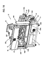
- FIG. 18 is a cutaway, front elevation view of a modified test vessel provided in accordance with the present invention.
- FIG. 19 is a top plan view of the dissolution test apparatus illustrated in FIGS. 1-3 with the spindle head assembly removed.
- Dissolution test apparatus includes a frame assembly, generally designated 12 , having a front section, generally designated 14 , and a rear section, generally designated 16 .
- the structure defining frame assembly 12 includes an upper plate 18 and a lower or base plate 21 .
- a water bath container 23 is interposed between upper and lower plates 18 and 21 , and a vessel plate 25 is mounted on upper plate 18 .
- Vessel plate 25 has a plurality of mounting apertures to enable vessel plate 25 to hold a plurality of test vessels 27 that extend into the interior of water bath container 23 .
- Test vessels 27 are preferably of the industry-acceptable type, as understood by persons skilled in the art.
- Water bath container 23 is adapted to contain a water bath (or a volume of some other suitable heat transfer medium) for regulating the temperature of media held in test vessels 27 at a predetermined temperature.
- a power box 29 for supplying electrical power to various operative components of dissolution test apparatus 10 is mounted in rear section 16 of dissolution test apparatus 10 .
- a combined water heater/pump unit 31 is mounted in rear section 16 .
- Heater/pump unit 31 includes appropriate fluid input and output components (not specifically shown) for circulating heated water (or other heat transfer medium) through the interior of water bath container 23 to maintain the desired test vessel media temperature.
- Heater/pump unit 31 is preferred for its compact design, although it will be understood that separate heater and pump devices could be employed in the present embodiment.
- Power box 29 and heater/pump unit 31 are both disposed below a drip pan 33 that is removable from rear section 16 .
- a primary operative assembly of dissolution test apparatus 10 is a spindle head assembly, generally designated 200 .
- Spindle head assembly 200 advantageously integrates, houses and/or supports a number of operative components.
- spindle head assembly 200 includes, among other components, a plurality of test vessel agitation devices, sampling and temperature probe devices, and sample substance dosage delivery devices, all of which are more fully described hereinbelow.
- the number of such devices associated with spindle head assembly 200 corresponds to the number of test vessels 27 supported by vessel plate 25 .
- the terms “probe,” “probe device,” “probe mechanism,” “sampling device” and “sampling mechanism” are used interchangeably to refer to a device that includes one or more probes or instruments.
- probes or instruments examples include one or more cannulae for aspirating or withdrawing fluid from a test vessel 27 , and/or for dispensing or returning fluid to a test vessel 27 , and further includes temperature probes and fiber optic probes for operative insertion into a test vessel 27 .
- each test vessel agitation device includes a rotatable agitator shaft 274 equipped with an agitation element such as a paddle 276 , although it will be understood that other types of agitation elements could be provided.
- a basket or other suitable element that is supported at the lower end of agitator shaft 274 could be substituted for paddle 276 in order to hold certain types of sample dosages intended for dissolution within test vessels 27 .
- spindle head assembly 200 also supports a plurality of evaporation covers 278 . When lowered onto the open top ends of test vessels 27 (see FIG.
- evaporation covers 278 seal off the respective interiors of test vessels 27 to a degree sufficient to substantially prevent undue loss of gaseous phase media from test vessels 27 during operation of dissolution test apparatus 10 , as well as to prevent degradation of the various operative components of spindle head assembly 200 due to condensation from sources escaping from test vessels 27 .
- the integration of the various devices utilized in dissolution testing procedures into a single spindle head assembly 200 significantly increases the utility of dissolution test apparatus 10 as a research tool.
- FIGS. 1A and 1B illustrate spindle head assembly 200 in its non-operative or rear position, at which position spindle head assembly 200 is generally disposed above rear section 16 of frame assembly 12 and provides unobstructed access and visibility to vessel plate 25 , test vessels 27 , and water bath container 23 .
- FIGS. 2A and 2B illustrate spindle head assembly 200 in its intermediate or front raised position, at which position spindle head assembly 200 is generally disposed above front section 14 of frame assembly 12 . In its rear position and front raised position, the various components of spindle head assembly 200 do not perform operations within test vessels 27 .
- FIGS. 3A and 3B illustrate spindle head assembly 200 in its operative or front lowered position, at which position spindle head assembly 200 is lowered such that evaporation covers 278 contact and cover the open tops of corresponding test vessels 27 . In the front lowered position, agitation shafts 274 and their respective paddles 276 (see, e.g., FIG. 1A ) as well as other components of spindle head assembly 200 can operate within test vessels 27 .
- spindle head transport assembly 60 is preferably provided in the form of a movable upright “goalpost” configuration.
- spindle head transport assembly 60 includes left and right upright lateral or vertical support members, generally designated 65 A and 65 B, respectively, spaced from each other on each side of frame assembly 12 .
- Spindle head assembly 200 is movably interconnected between left and right lateral support members 65 A and 65 B, and is mechanically raised and lowered along lateral support members 65 A and 65 B in a generally vertical direction. The automated vertical travel of spindle head assembly 200 along lateral support members 65 A and 65 B enables movement of spindle head assembly 200 between its front raised position (see FIGS.
- each lateral slide rail 105 A and 105 B includes a front stop member 107 A and 107 B, respectively, and the rear end of each lateral slide rail 105 A and 105 B likewise includes a rear stop member 109 A and 109 B, respectively (see also FIG. 19 ).
- front stop members 107 A and 107 B and rear stop members 109 A and 109 B respectively provide the forward-most and rearward-most limits of travel along lateral slide rails 105 A and 105 B.
- the horizontal travel of lateral support members 65 A and 65 B (and thus that of spindle head assembly 200 ) along lateral slide rails 105 A and 105 B enables movement of spindle head assembly 200 between its rear position (see FIGS. 1A and 1B ) and its front raised position (see FIGS. 2 A and 2 B).
- dissolution test apparatus 10 provides the most efficiency and facility in use when movement of spindle head assembly 200 between the rear position and the front raised position is effected by manual manipulation by the operator of dissolution test apparatus 10 .
- a handle 202 is attached to spindle head assembly 200 as shown in FIGS. 1A , 2 A and 3 A. It will be understood, however, that movement of spindle head assembly 200 between the rear position and the front raised position could be automated through the utilization of appropriate motorized drive and transmission means, if desired.
- Dissolution test apparatus 10 further includes other components illustrated in FIGS. 1-3 .
- a data output peripheral device such as an on-board printer device 35 for hard-copy data archival, and a master ON/OFF power switch 37 for dissolution test apparatus 10 , are each mounted at one side of rear section 16 of dissolution test apparatus 10 .
- a rear housing 39 of dissolution test apparatus 10 which may or may not be movable with spindle head assembly 200 , includes a cooling fan unit 41 and a group of fluid and/or electrical input and output connections, generally designated 43 . As shown in FIGS.
- dissolution test apparatus 10 includes an input/output interface in the form of a control panel 45 communicating with an associated programmable systems control module (not specifically shown).
- control panel 45 includes a display device such as an LCD (liquid crystal display) screen 45 A and a number of alphanumeric and/or symbolic keypads, generally designated 45 B.
- Keypads 45 B enable an operator of dissolution test apparatus 10 to input a variety of dissolution test parameters and operational instructions, as well as commands for movement of spindle head assembly 200 .
- the operator can use keypads 45 B to write a complete program or set of instructions to be executed by dissolution test apparatus 10 .
- control panel 45 and its associated operative components are integrated into spindle head assembly 200 .
- a rack 47 A or 47 B is respectively formed or attached to each tapered side of lower plate 21 of frame assembly 12 .
- Each rack 47 A and 47 B holds a plurality of precisely dimensioned balls 49 for use in ensuring that dissolution test apparatus 10 is operating in accordance with USP standards.
- balls 49 are used to ensure that each agitator shaft 274 is correctly positioned in relation to the lowermost inside surface of each corresponding test vessel 27 .
- this calibration procedure is greatly facilitated by the movable, integrated design of spindle head assembly 200 . That is, when spindle head assembly 200 is in the rear position shown in FIGS.
- each ball 49 can be easily dropped into each test vessel 27 .
- Spindle head assembly 200 is then moved through the intermediate, front raised position shown in FIGS. 2A and 2B , and ultimately into the operative, front lowered position shown in FIGS. 3A and 3B , at which point each agitator shaft 274 has been lowered into its associated test vessel 27 .
- each agitator shaft 274 is adjusted until its lowermost end surface (which may be the bottom surface of paddle 276 ) contacts a ball 49 . In this manner, the height of each agitator shaft 274 in relation to the bottom of its test vessel 27 is brought into compliance with USP requirements.
- front section 14 of frame assembly 12 is tapered such that its width varies and narrows in the general direction from the rear of dissolution test apparatus 10 to the front of dissolution test apparatus 10 .
- front section 14 could be described as being triangular or trapezoidal.
- front section 14 preferably has at least two sides or edges 14 A and 14 B defining the tapered width, and can also have a front side or edge 14 C at which sides 14 A and 14 B terminate.
- the tapered profile can be implemented, for example, by tapering the area of the front region of upper plate 18 and/or vessel plate 25 .
- sides or edges 14 A, 14 B and 14 C could be represented by the sides or edges of either upper plate 18 , vessel plate 25 , or both upper plate 18 and vessel plate 25 . That is, the tapered configuration could be defined by either varying an area of upper plate 18 and/or an area of vessel plate 25 .
- test vessels 27 This configuration enables a tapered, triangular or trapezoidal array of test vessels 27 , and is best implemented with the use of four or more (e.g., eight) test vessels 27 .
- the arrangement results in the maximum number of test vessels 27 being situated generally along sides 14 A and 14 B of front section 14 .
- three test vessels 27 are situated along each side 14 A and 14 B.
- the test vessel array forms a triangle having three sides S 1 , S 2 and S 3 , in which side S 1 is runs parallel to side 14 A and side S 2 runs parallel to side 14 B.
- Sides S 1 , S 2 and S 3 can be conceptualized as vessel alignment lines or directions along which all, or at least a majority of, test vessels 27 are situated.
- test vessels 27 increases the visibility of test vessels 27 while dissolution test apparatus 10 is operating in the front lowered position, especially the outermost situated test vessels 27 , and further increases the accessibility of test vessels 27 when spindle head assembly 200 is located at its rear position for cleaning, alignment, removal and other purposes. While the remaining two test vessels 27 are illustrated as being situated in the inside region of vessel plate 25 away from sides 14 A and 14 B, these latter two test vessels 27 are often used as control vessels during dissolution procedures. Visibility of these latter two “inside” test vessels 27 is thus not as critical as visibility of the “outside” test vessels 27 .
- FIG. 4 illustrates left lateral support member 65 A.
- Left lateral support member 65 A includes a body 67 A having a cavity 69 A adapted for facing spindle head assembly 200 , and further includes a lower bore 71 A formed at its lower end and a vertically-oriented, toothed rack gear 73 A mounted along its rear side.
- a vertically-disposed slide track 75 A is mounted to the innermost side of cavity 69 A.
- a slide block 77 A is movably connected to slide track 75 A, and is adapted for attachment to spindle head assembly 200 .
- a home flag sensor 79 A preferably of the optical type, is mounted to slide block 77 A.
- Home flag sensor 79 A interacts with a stop pin 81 A (serving as the home flag) so that dissolution test apparatus 10 can determine when spindle head assembly 200 has reached the front lowered position.
- Stop pin 81 A extends into cavity 69 A from a surface of left lateral support member 65 A that is located in the lower region of left lateral support member 65 A.
- a guide rod holder 87 A is mounted at the lower end of left lateral support member 65 A.
- guide rod holder 87 A is generally L-shaped to facilitate its mounting to left lateral support member 65 A.
- Guide rod holder 87 A includes a through-bore 91 A for guiding a left guide rod 95 A (see FIG. 7 ) associated with spindle head assembly 200 .
- Left guide rod 95 A is further described hereinbelow.
- one or more bushings 101 A are inserted into lower bore 71 A of left lateral support member 65 A.
- Left lateral support member 65 A is movably supported by left slide rail 105 A (see FIGS. 1A , 2 A, and 3 A) by extending left slide rail 105 A through lower bore 71 A.
- a protrusion 125 extends downwardly from a lower edge 127 of left lateral support member 65 A. The function of protrusion 125 is described hereinbelow.
- FIGS. 5 and 5A illustrate right lateral support member 65 B.
- Right lateral support member 65 B includes many of the same components as left lateral support member 65 A, which are similarly enumerated as follows: a body 67 B having a cavity 69 B adapted for facing spindle head assembly 200 ; a lower bore 71 B; a vertically-oriented, toothed rack gear 73 B; a vertically-disposed slide track 75 B; a slide block 77 B movably connected to slide track 75 B; a home flag sensor 79 B; a guide rod holder 87 B with a through-bore 91 B for guiding a right guide rod 95 B (shown in FIGS.
- a stop pin extends into cavity 69 B from a surface of right lateral support member 65 B that is located in the upper region of right lateral support member 65 B, instead of in the lower region thereof.
- the stop pin for right lateral support member 65 B is concealed by home flag sensor 79 B and thus is not specifically shown.
- Home flag sensor 79 B interacts with this stop pin (again serving as the home flag) at the upper location so that dissolution test apparatus 10 can determine when spindle head assembly 200 has reached the front raised position.
- the second difference is that a protrusion such as protrusion 125 in FIG. 4A is not necessary in the case of right lateral support member 65 B.
- a lift drive assembly is mounted on base support plate 205 and provides the power and connections needed to operatively couple spindle head assembly 200 to left and right lateral support members 65 A and 65 B, and accordingly to enable spindle head assembly 200 to be automatically driven between its front raised and front lowered positions.
- Lift drive assembly 215 includes a gearbox mounting plate 217 mounted to base support plate 205 , and a lift motor mounting plate 219 mounted to gearbox mounting plate 217 .
- a gearbox 221 is attached to gearbox mounting plate 217
- a lift motor 223 is likewise attached to lift motor mounting plate 219 .
- the shaft of lift motor 223 is connected to gearbox 221 through a motor-to-gearbox coupling 225 .
- Gearbox 221 using a worm gear drive or similar arrangement, translates the torque produced by lift motor 223 into transversely-oriented torque provided to drive shafts 227 A and 227 B disposed on each side of gearbox 221 and connected to gearbox 221 through gearbox shaft couplings 229 A and 229 B.
- the outer ends of drive shafts 227 A and 227 B are respectively supported in pillow blocks 231 A and 231 B mounted to base support plate 205 . As best shown in FIG.
- toothed gears or pinions 233 A and 233 B are respectively supported on the outer ends of drive shafts 227 A and 227 B at each pillow block 231 A and 231 B.
- each pinion 233 A and 233 B meshes with its corresponding left or right vertical rack 73 A or 73 B (see FIGS. 4 and 5 ) to enable spindle head assembly 200 to be driven along left and right slide tracks 75 A and 75 B between its front raised and front lowered positions.
- left guide rod 95 A of spindle head assembly 200 is illustrated.
- left guide rod 95 A extends through a bore of base support plate 205 and through-bore 91 A of guide rod holder 87 A of left lateral support member 65 A.
- Right guide rod 95 B is analogously supported, but does not include the features of left guide rod 95 A that will now be described.
- left guide rod 95 A is adjustably supported by base support plate 205 by threading a nut 131 onto a threaded upper portion of left guide rod 95 A.
- Left guide rod 95 A differs from right guide rod 95 B in that a lift rod 135 is movably disposed within left guide rod 95 A. Lift rod 135 is prevented from completely dropping out of left guide rod 95 A by threading one or more nuts 137 onto a threaded portion of lift rod 135 .
- a lift rod sensor 139 is operatively positioned in alignment with lift rod 135 with the assistance of a mounting block 141 attached to base support plate 205 . As shown in FIG. 7B , the lowermost end of lift rod 135 protrudes beyond the bottom surface of guide rod holder 87 A. When spindle head assembly 200 is in its proper rear position, lift rod 135 does not contact upper plate 18 of frame assembly 12 .
- Lift rod 135 serves as a home flag for lift rod sensor 139 to prevent damage to both dissolution test apparatus 10 and the operative components of spindle head assembly 200 . Such damage might result from an operator erroneously attempting to lower spindle head assembly 200 while spindle head assembly 200 is in its rear position, instead of first transporting spindle head assembly 200 to the front raised position and then correctly causing spindle head assembly 200 to lower into the front lowered, operative position. Referring generally to FIG.
- dissolution test apparatus 10 includes a left alignment hole 144 A through which left guide rod 95 A (and thus lift rod 135 ) travels during movement of spindle head assembly 200 from the front raised position to the front lowered position.
- Dissolution test apparatus 10 likewise includes a right alignment hole 144 B (see FIG. 1A ) through which right guide rod 95 B travels.
- Left and right guide rods 95 A and 95 B and their corresponding left and right alignment holes 144 A and 144 B cooperate to maintain spindle head assembly 200 in proper alignment with vessel plate 25 and each individual test vessel 27 as spindle head assembly 200 moves from the front raised position to the front lowered position.
- alignment hole 144 A is formed in vessel plate 25 . Accordingly, when spindle head assembly 200 travels from the front raised position to the front lowered position, lift rod 135 does not encounter any intervening structure to cause its upper end to break the plane of lift rod sensor 139 .
- left and right guide rod tubes 146 A and 146 B are respectively disposed in register with their corresponding alignment holes 144 A and 144 B.
- each guide rod 95 A and 95 B (including lift rod 135 associated with left guide rod 95 A) moves through its corresponding alignment hole 144 A and 144 B into guide rod tube 146 A and 146 B in order to prevent guide rods 95 A and 95 B from injuring an operator of dissolution test apparatus 10 .
- vessel alignment means be provided for centering each test vessel 27 with respect to its mounting aperture in vessel plate 25 and/or its corresponding agitator shaft 274 .
- the alignment means can take the form of a vessel alignment ring, for which novel embodiments are described in U.S. patent application Ser. No. 09/697,963, assigned to the assignee of the present invention, the entire disclosure of which is incorporated herein.
- front and rear latches 155 A and 155 B are mounted in recesses on at least one side of upper plate 18 of frame assembly 12 .
- Front latch 155 A assists in locking spindle head assembly 200 in the front raised (and consequently front lowered) position
- rear latch 155 B likewise assists in locking spindle head assembly 200 in the rear position.
- One preferred design of front latch 155 A is illustrated in FIGS. 8A and 8B
- one preferred design of rear latch 155 B is illustrated in FIGS. 9A and 9B . Referring first to FIGS.
- front latch 155 A includes a latch block 157 A having an upper recess 159 A in which an L-shaped latch head 161 A pivots about a pivot member 163 A.
- Latch head 161 A includes a handle 165 A to facilitate its manipulation by an operator of dissolution test apparatus 10 .
- a spring 167 A urges latch head 161 A upwardly away from recess 159 A such that latch head 161 A protrudes above a top surface 169 A of latch block 157 A.
- Latch head 161 A interacts with protrusion 125 of left lateral support member 65 A (see FIG. 4 A).
- latch head 161 A engages protrusion 125 to lock spindle head assembly 200 into position.
- latch head 161 A Prior to moving spindle head assembly 200 from the front raised position to the rear position, latch head 161 A must be pushed downwardly against the biasing force of spring 167 A to disengage latch head 161 A from protrusion 125 .
- rear latch 155 B has a structure similar to that of front latch 155 A, and functions analogously to releasably lock spindle head assembly 200 into its rear position.
- spindle head assembly 200 includes a spindle mechanism, generally designated 270 , and a combined probe/dosage delivery mechanism, generally designated 310 .
- a spindle drive motor 240 provides power to each spindle mechanism 270 through transmission means.
- transmission means includes an endless belt 242 that operatively drives pulleys 244 of each spindle mechanism 270 .
- a plurality of idler pulleys 246 are provided to maintain proper tension of belt 242 throughout spindle head assembly 200 .
- a printed circuit board (PCB) 248 contains electronics for controlling the operation of spindle drive motor 240 .
- Spindle head assembly 200 also includes a main PCB 251 and a lift motor PCB 253 mounted to a back plate 255 of spindle head assembly 200 , and a cannula master PCB 257 and a temperature probe PCB 259 mounted to a stiffening plate 261 of spindle head assembly 200 .
- spindle head cover 265 is hinged to spindle head assembly 200 at a rear location so that spindle head cover 265 can be conveniently opened from the front to provide easy access into the confines of spindle head assembly 200 .
- a spindle 272 is press-fitted onto agitator shaft 274 and rotates within a spindle hub or bearing housing 281 with one or more bearings 283 .
- pulley 244 is adapted to be operatively driven by spindle drive motor 240 of spindle head assembly 200 through the engagement of pulley 244 with belt 242 .
- Pulley 244 is retained by a spindle collar 285 , which contacts the upper portion of spindle 272 .
- An agitator shaft collar 287 contacting agitator shaft 274 is disposed above spindle collar 285 .
- an electric or electromagnetic clutch/brake device 289 is operatively associated with spindle mechanism 270 .
- Clutch/brake device 289 alternately engages and disengages spindle 272 to provide control over the operation of spindle mechanism 270 .
- the brake portion prevents spindle 272 (and thus agitator shaft 274 and paddle 276 ) from rotating in an unintended manner when the clutch portion is disengaged from spindle 272 .
- An operator of dissolution test apparatus 10 can thus program the sequence through which agitator shafts 274 operate in the media of test vessels 27 , and can selectively start or stop one or more of spindle mechanisms 270 to facilitate manual procedures.
- spindle head cover 265 includes an aperture 291 to accommodate spindle mechanism 270 .
- base support plate 205 includes a similar aperture 293 .
- Agitator shaft collars 287 can be seen disposed above spindle head cover 265 in FIGS. 1A , 2 A and 3 A.
- Combined probe/dosage delivery mechanism 310 integrates both a dosage delivery mechanism and a probe mechanism, and includes a main body 312 that defines both a dosage delivery passage 314 and a probe passage 316 .
- a dosage delivery tube 321 which could be constructed from either a clear material or an opaque material, is mounted in alignment with an inlet side of dosage delivery passage 314 .
- a dosage retaining element such as a rotatable paddle or trap door 323 is operatively connected to a rotary actuator or solenoid 325 , and alternately defines open and closed states of dosage delivery passage 314 .
- the closed state is illustrated in FIGS. 13A and 13B , in which paddle 323 covers the open upper end of dosage delivery tube 321 and thereby prevents a dosage unit such as a tablet from dropping through dosage delivery passage 314 and into the media contained in a test vessel 27 situated below combined probe/dosage delivery mechanism 310 .
- spindle head cover 265 includes a dosage unit inlet collar 327 in registry with an aperture (not specifically shown) to permit an operator to load a dosage unit into combined probe/dosage delivery mechanism 310 .
- base support plate 205 includes an aperture 329 to accommodate the delivery of dosage units into test vessels 27 . Accordingly, dosage unit inlet collar 327 , aperture 329 and dosage delivery passage 314 conjoin to define a dosage delivery path to each test vessel site.
- an operator of dissolution test apparatus 10 loads one or more dosage units through one or more dosage unit inlet collars 327 while each dosage delivery passage 314 is in the closed state.
- the lowermost dosage unit will come to rest on, and be supported by, each paddle 323 when situated in the closed state.
- one or more paddles 323 will be rotated into the open state, thereby releasing a dosage unit into its corresponding test vessel 27 .
- Rotary actuator 325 includes a spring-return element so that paddle 323 returns to the closed state once rotary actuator 325 is de-energized.
- a probe holder 345 is movably disposed in probe passage 316 .
- Probe holder 345 can be adapted to hold a variety of different types of probes.
- probe holder 345 holds a sample media withdrawal cannula 347 with a filter element 349 , a sample media return cannula 351 , and a temperature probe 353 such as the thermistor type.
- Main body 312 is adapted to support and provide a light shield for an optical encoder 355 .
- Optical encoder 355 senses the vertical position of probe holder 345 with respect to main body 312 (for instance, the high point of probe holder 345 ), such as by sensing a change in distance provided by a notch (not shown) in probe holder 345 .
- a stepper motor 357 is mounted to main body 312 to drive probe holder 345 vertically along the direction dictated by probe passage 316 .
- Stepper motor 357 operatively engages a pinion gear 359 which meshes with a toothed rack 361 (see, e.g., FIG. 17 ) formed on probe holder 345 .
- probe holder 345 can be lowered into the media contained in its corresponding test vessel 27 , measure temperature, draw a predetermined quantity of filtered sample from test vessel 27 (which is pumped to appropriate analytical equipment), return the unused portion of the sample back into test vessel 27 , and then be retracted back out of the media until the next sampling or probing procedure.
- spindle head cover 265 includes an aperture 363 to accommodate the probes and/or instruments held in probe holder 345 , as well as their respective connections or fittings.
- base support plate 205 includes a similar aperture 365 .
- each evaporation cover 278 includes apertures for accommodating the operation of agitator shaft 274 , dosage delivery passage 314 , and probe holder 345 and/or its individual probes or instruments.
- Combined probe/dosage delivery mechanism 310 as illustrated in FIGS. 13A and 13B is preferred for its compactness and because it reduces complexity as well as the total number of operative modules associated with spindle head assembly 200 .
- the probing and dosage delivery functions could be implemented in separate devices and mounted to spindle head assembly 200 in place of each combined probe/dosage delivery mechanism 310 .
- a separate dosage delivery device is generally designated 370 .
- Dosage delivery device 370 includes an upper dosage unit drop tube 372 secured to a lower dosage unit drop tube 374 by means of a snap ring 376 fitted into an annular groove formed on an inside surface of lower dosage unit drop tube 374 .
- a rotatable paddle or trap door 378 is situated at the bottom end of upper dosage unit drop tube 372 and is operatively connected to a horizontally-oriented paddle shaft 381 .
- paddle 378 of separate dosage delivery device 370 rotates about an axis generally transverse with the dosage delivery path.
- paddle shaft 381 is defined by paddle shaft 381 .
- paddle 378 of separate dosage delivery device 370 is operatively connected through several linkage components to a linear actuator 385 such as the solenoid device shown in FIG. 16 .
- the linkage components include a lever arm 387 interconnecting paddle shaft 381 with a pivoting member 389 , and a yoke fitting 391 interconnecting pivoting member 389 with a linkage arm 393 .
- Linkage arm 393 is adapted for connection with another yoke fitting 395 , shown in FIG. 16 , which in turn is operatively connected to the movable component of linear actuator 385 .
- Probe holder 345 is movably disposed in a probe passage defined by a sleeve 412 .
- probe holder 345 can be adapted to hold a variety of different types of probes or instruments, such as liquid withdrawal cannula 347 with filter element 349 , liquid dispensing cannula 351 , and temperature probe 353 , and its movement can be sensed by optical encoder 355 .
- a stepper motor 414 drives the movement of probe holder 345 through a pinion gear 416 in meshing engagement with toothed rack 361 formed on probe holder 345 .
- test vessels 27 are heated individually and directly by heater elements, instead of being heated collectively by submersion in a water bath. Accordingly, water bath container 23 and heater/pump unit 31 illustrated in FIGS. 1-3 can be eliminated and replaced with what may be termed direct or waterless vessel heating technology.
- a direct vessel heating system generally designated 420 , is illustrated. A heater element 422 is wrapped around the outer surface of a test vessel 424 , and is adhered to test vessel 424 through the use of either a pressure-sensitive or heat-activated adhesive.
- Test vessel 424 is insulated from the ambient surroundings by inserting test vessel 424 into a vessel isolation jacket 426 , which is preferably constructed from a clear material, so that a gap 428 is defined between test vessel 424 and vessel isolation jacket 428 .
- a modified vessel plate 430 is provided to accommodate this configuration.
- Heater element 422 has a laminated structure that includes a plurality of thin films that are preferably constructed from a clear material.
- a heat conductive element such as one or more electrically resistive wires is embedded in one or more of the films, and supplies heat energy to the media contained in test vessel 424 to maintain temperature at a preset level.
- a temperature-sensing element such as the RTD type can also be embedded in one or more of the films to control temperature.
- an embedded protective sensor such as the thermistor type can be provided to prevent a runaway temperature event.
- heating system control circuitry When direct vessel heating technology is utilized, heating system control circuitry, provided on-board with dissolution test apparatus 10 in communication with the main control circuitry, is employed to coordinate the respective operations of heater elements 422 (including its heat conductive element, temperature sensing element, and protective sensor) and temperature probe 353 of spindle head assembly 200 (see FIGS. 13 A and 13 B).
- the heating system control circuitry can simultaneously and independently operate and control heating-related functions at each test vessel 424 installed in dissolution test apparatus 10 , with very good accuracy and in accordance with instructions programmed by an operator. For example, depending on the experimental procedures being implemented, each test vessel 424 can be maintained at a different set point temperature or can be subjected to a different variable temperature profile. Novel embodiments of the direct vessel heating technology are further described in U.S. patent application Ser. No. 09/603,305, assigned to the assignee of the present invention, the entire disclosure of which is incorporated herein.
- dissolution test apparatus 10 comprises a plurality of fully functional, individually controllable dissolution test systems. That is, each test vessel 27 effectively has its own dissolution test system.
- spindle head assembly 200 contains all operative components of dissolution test apparatus 10 that are contemplated to require adjustment, manipulation, observation and/or replacement on a regular basis. These components are easily accessed by removing spindle head cover 265 . Furthermore, these components are easily transported out of the way from test vessels 27 with minimal time and effort by moving spindle head assembly 200 from the front lowered position to the front raised position and to the rear position, so that test vessels 27 can be easily accessed.
- the tapered, triangular or trapezoidal shape of front section 14 of dissolution test apparatus 10 enables a high degree of visibility of test vessels 27 during their operation.
Priority Applications (5)
| Application Number | Priority Date | Filing Date | Title |
|---|---|---|---|
| US09/795,819 US6962674B2 (en) | 2001-02-28 | 2001-02-28 | Dissolution test apparatus |
| JP2002569906A JP2004519673A (ja) | 2001-02-28 | 2002-02-12 | 溶解試験装置 |
| DE60215476T DE60215476T2 (de) | 2001-02-28 | 2002-02-12 | Vorrichtung zur prüfung der auflösung von produkten |
| EP02707834A EP1373859B1 (de) | 2001-02-28 | 2002-02-12 | Vorrichtung zur prüfung der auflösung von produkten |
| PCT/US2002/005207 WO2002071033A2 (en) | 2001-02-28 | 2002-02-12 | Dissolution test apparatus |
Applications Claiming Priority (1)
| Application Number | Priority Date | Filing Date | Title |
|---|---|---|---|
| US09/795,819 US6962674B2 (en) | 2001-02-28 | 2001-02-28 | Dissolution test apparatus |
Publications (2)
| Publication Number | Publication Date |
|---|---|
| US20020119076A1 US20020119076A1 (en) | 2002-08-29 |
| US6962674B2 true US6962674B2 (en) | 2005-11-08 |
Family
ID=25166536
Family Applications (1)
| Application Number | Title | Priority Date | Filing Date |
|---|---|---|---|
| US09/795,819 Expired - Lifetime US6962674B2 (en) | 2001-02-28 | 2001-02-28 | Dissolution test apparatus |
Country Status (5)
| Country | Link |
|---|---|
| US (1) | US6962674B2 (de) |
| EP (1) | EP1373859B1 (de) |
| JP (1) | JP2004519673A (de) |
| DE (1) | DE60215476T2 (de) |
| WO (1) | WO2002071033A2 (de) |
Cited By (19)
| Publication number | Priority date | Publication date | Assignee | Title |
|---|---|---|---|---|
| US20050277184A1 (en) * | 2004-06-07 | 2005-12-15 | Bargh Adrian N | Stirring system for cell culture |
| US20060260423A1 (en) * | 2005-05-17 | 2006-11-23 | Jasco Corporation | Dissolution tester |
| US20060260422A1 (en) * | 2005-05-17 | 2006-11-23 | Jasco Corporation | Dissolution tester |
| US20070292309A1 (en) * | 2006-06-15 | 2007-12-20 | Logan Instruments Corp. | Pharmaceutical product release rate testing device |
| WO2008086542A2 (en) * | 2007-01-10 | 2008-07-17 | Varian, Inc. | Automated microsampling dissolution test system |
| US20080267007A1 (en) * | 2005-10-12 | 2008-10-30 | Stardale Ltd. | Device for Mixing or Amalgamating Products in Liquid, Granular or Powder Form |
| WO2008157584A3 (en) * | 2007-06-20 | 2009-03-05 | Varian Inc | Apparatus and methods for automatic insertion, debubbling, cleaning and calibration of a spectral probe during dissolution testing |
| US20090162246A1 (en) * | 2007-12-20 | 2009-06-25 | Chien-Chung Fu | Sample carrying apparatus capable of revolving sample |
| EP2090364A2 (de) | 2008-02-14 | 2009-08-19 | Varian, Inc. | Auflösungstestbehälter mit integrierter Zentriergeometrie |
| US20090208373A1 (en) * | 2008-02-14 | 2009-08-20 | Varian, Inc. | Captive evaporation cover for dissolution systems |
| US20090207691A1 (en) * | 2008-02-14 | 2009-08-20 | Varian, Inc. | Dissolution test vessel with rotational agitation |
| US20100107752A1 (en) * | 2008-10-30 | 2010-05-06 | Fernando C J Anthony | Dissolution testing with in-situ gravimetric volume measurement |
| US20110003323A1 (en) * | 2009-07-01 | 2011-01-06 | The Automation Partnership (Cambridge) Limited | Bioreactor systems and associated methods of processing bioreactor vessels |
| EP2306172A2 (de) | 2009-10-01 | 2011-04-06 | Agilent Technologies, Inc. | Auflösungstestbehälter mit integrierter Vertikalitätssteuerung |
| EP2325633A2 (de) | 2009-11-24 | 2011-05-25 | Agilent Technologies, Inc. | Auflösungstestbehälter mit integrierter Zentrierung |
| DE102011011186A1 (de) | 2010-03-02 | 2011-09-08 | Agilent Technologies Inc. | Prüfung der Auflösung mittels Infrarot-Temperaturmessung |
| US20120042737A1 (en) * | 2010-04-13 | 2012-02-23 | New Jersey Institute Of Technology | Novel dissolution testing system and apparatus with off-center impeller |
| US20120232824A1 (en) * | 2011-03-11 | 2012-09-13 | Distek, Inc. | Centrally controlled modular motorized testing |
| US8659825B2 (en) | 2007-12-20 | 2014-02-25 | National Tsing Hua University | Sample carrying apparatus capable of revolving sample |
Families Citing this family (19)
| Publication number | Priority date | Publication date | Assignee | Title |
|---|---|---|---|---|
| US7534395B2 (en) * | 2004-04-27 | 2009-05-19 | Beckman Coulter, Inc. | Hysteresis compensation system |
| JP4648083B2 (ja) * | 2005-05-17 | 2011-03-09 | 日本分光株式会社 | 溶出試験器 |
| KR20160067985A (ko) | 2005-11-08 | 2016-06-14 | 버텍스 파마슈티칼스 인코포레이티드 | Atp 결합 카세트 수송체의 헤테로사이클릭 조정제 |
| US8158059B2 (en) | 2005-12-30 | 2012-04-17 | Sotax Corporation | Integrated dissolution processing and sample transfer system |
| GB2436143A (en) * | 2006-03-15 | 2007-09-19 | Astech Projects Ltd | Multiple sample processing |
| US7850919B2 (en) * | 2007-02-28 | 2010-12-14 | Bruce Renslow | Liquid sample collector interface |
| DE102007058718A1 (de) | 2007-12-06 | 2009-06-10 | Erweka Gmbh | Vorrichtung und Verfahren zur automatischen Freisetzung und Messung von Wirkstoffen aus einer Arzneizubereitung |
| JP5552275B2 (ja) * | 2009-07-28 | 2014-07-16 | 富山産業株式会社 | 溶出試験器 |
| CA2795804C (en) | 2010-04-07 | 2021-10-26 | Vertex Pharmaceuticals Incorporated | Pharmaceutical compositions of 3-(6-(1-(2,2-difluorobenzo[d][1,3]dioxol-5-yl) cyclopropanecarboxamido)-3-methylpyriodin-2-yl)benzoic acid and administration thereof |
| US20120109567A1 (en) * | 2010-11-03 | 2012-05-03 | Anna Bobasheva | Systems and methods for acquiring and managing sensor data related to dissolution testing apparatus |
| CN102590461A (zh) * | 2012-01-10 | 2012-07-18 | 天津市天大天发科技有限公司 | 可调节溶出杯位置及角度的药溶仪装置 |
| DE102012211207A1 (de) * | 2012-06-28 | 2014-01-02 | Hamilton Bonaduz Ag | Pipettiervorrichtung mit Hysteresebremse |
| CA2968130C (en) * | 2014-11-18 | 2022-08-16 | Vertex Pharmaceuticals Incorporated | Process of conducting high throughput testing high performance liquid chromatography |
| CN106943916B (zh) * | 2017-03-09 | 2020-01-21 | 滨州富明化工有限公司 | 一种化工物料搅匀装置 |
| CN108499455A (zh) * | 2018-03-07 | 2018-09-07 | 谢斌 | 一种实验室化学药品批量混合摇匀装置 |
| CN108786587A (zh) * | 2018-07-13 | 2018-11-13 | 沈阳大学 | 一种三维轴向液流发生的六轴同步搅拌混匀装置 |
| CN109142658A (zh) * | 2018-08-23 | 2019-01-04 | 沈阳奥吉娜药业有限公司 | 篮轴输送升降旋转组件 |
| CN109464932A (zh) * | 2018-11-05 | 2019-03-15 | 禄根仪器(镇江)有限公司 | 一种溶出仪专用多区域同步调速机构 |
| CN116371283B (zh) * | 2023-06-05 | 2023-08-25 | 福建省德尚电子材料有限公司 | 一种光刻胶生产用原料混合设备及其混合方法 |
Citations (12)
| Publication number | Priority date | Publication date | Assignee | Title |
|---|---|---|---|---|
| US3787185A (en) * | 1972-03-02 | 1974-01-22 | Beckman Ind Inc | Disruptor module |
| EP0121345A2 (de) | 1983-03-04 | 1984-10-10 | Akbar Noormohammadi | Vorrichtung zur Auflösungsuntersuchung |
| EP0278374A2 (de) | 1987-02-06 | 1988-08-17 | Pharmatest Apparatebau Gmbh | Vorrichtung zur Bestimmung der Wirkstoff-Freigabe von pharmazeutischen Produkten |
| EP0635713A1 (de) | 1993-07-14 | 1995-01-25 | Zymark Corporation | Automatisches Auflösungsuntersuchungssystem |
| US5412979A (en) * | 1993-05-03 | 1995-05-09 | Temple University - Of The Commonwealth System Of Higher Education | Method and apparatus for dissolution testing of a dosage form |
| WO1995023329A1 (en) | 1994-02-25 | 1995-08-31 | Distek Inc. | Dissolution testing apparatus |
| US5682001A (en) * | 1996-04-01 | 1997-10-28 | Hanson Research Corp. | Dissolution test apparatus with counterbalance system |
| US6040192A (en) * | 1993-02-01 | 2000-03-21 | Labsystems Oy | Method and means for magnetic particle specific binding assay |
| EP1052498A1 (de) | 1999-05-11 | 2000-11-15 | Sotax Ag | Verfahren, Patrone und Vorrichtung zum Einbringen eines teilchenförmigen Materials in eine Flüssigkeit |
| US6170980B1 (en) | 1999-04-09 | 2001-01-09 | Source For Automation, Inc. | Automated tablet dissolution apparatus |
| US6336739B1 (en) * | 2001-03-02 | 2002-01-08 | Luke Lee | Air bath dissolution tester |
| US6497157B1 (en) * | 1999-11-29 | 2002-12-24 | Distek, Inc. | Intrinsic dissolution apparatus with stationary sample holder |
Family Cites Families (14)
| Publication number | Priority date | Publication date | Assignee | Title |
|---|---|---|---|---|
| US815272A (en) * | 1905-03-15 | 1906-03-13 | Walter B Devereux | Agitating device. |
| DE2520591C3 (de) * | 1975-05-09 | 1980-11-06 | Hoechst Ag, 6000 Frankfurt | Verfahren und Vorrichtung zur kontinuierlichen Behandlung von wäßrigen Homo- und Copolymerisatdispersionen, deren Polymeranteil mindestens 50 Gew.-°/o polymerisier- |
| US4464340A (en) * | 1981-06-15 | 1984-08-07 | Burroughs Wellcome Co. | Dissolution flask |
| SE451164B (sv) * | 1982-03-22 | 1987-09-07 | Erik Ohlin | Apparat och sett for serieutspedning av en provvetska |
| US4803050A (en) * | 1985-07-22 | 1989-02-07 | Sequoia-Turner Corporation | Method and apparatus for liquid addition and aspiration in automated immunoassay techniques |
| FI930440A0 (fi) * | 1993-02-01 | 1993-02-01 | Labsystems Oy | Bestaemningsfoerfarande |
| US5321480A (en) * | 1993-05-06 | 1994-06-14 | Eastman Kodak Company | Fuser having a detachable belt |
| JP3411111B2 (ja) * | 1994-10-27 | 2003-05-26 | シスメックス株式会社 | 試料攪拌装置及び試料吸引装置 |
| US5904899A (en) * | 1997-05-15 | 1999-05-18 | Tosoh Corporation | Assaying apparatus and a vessel holder device in use with the assaying apparatus |
| US6241947B1 (en) * | 1998-01-27 | 2001-06-05 | Fuji Photo Film Co., Ltd. | Chemical analysis system and blood filtering unit |
| US6994827B2 (en) * | 2000-06-03 | 2006-02-07 | Symyx Technologies, Inc. | Parallel semicontinuous or continuous reactors |
| US6562301B1 (en) * | 2000-10-27 | 2003-05-13 | Varian, Inc. | Vessel centering system and method |
| US6582116B2 (en) * | 2001-09-24 | 2003-06-24 | Symyx Technologies, Inc. | Apparatus and method for mixing small volumes of reaction materials |
| JP2003232799A (ja) * | 2002-02-06 | 2003-08-22 | Hitachi High-Technologies Corp | 自動分析装置 |
-
2001
- 2001-02-28 US US09/795,819 patent/US6962674B2/en not_active Expired - Lifetime
-
2002
- 2002-02-12 JP JP2002569906A patent/JP2004519673A/ja active Pending
- 2002-02-12 EP EP02707834A patent/EP1373859B1/de not_active Expired - Lifetime
- 2002-02-12 WO PCT/US2002/005207 patent/WO2002071033A2/en active IP Right Grant
- 2002-02-12 DE DE60215476T patent/DE60215476T2/de not_active Expired - Lifetime
Patent Citations (14)
| Publication number | Priority date | Publication date | Assignee | Title |
|---|---|---|---|---|
| US3787185A (en) * | 1972-03-02 | 1974-01-22 | Beckman Ind Inc | Disruptor module |
| EP0121345A2 (de) | 1983-03-04 | 1984-10-10 | Akbar Noormohammadi | Vorrichtung zur Auflösungsuntersuchung |
| EP0278374A2 (de) | 1987-02-06 | 1988-08-17 | Pharmatest Apparatebau Gmbh | Vorrichtung zur Bestimmung der Wirkstoff-Freigabe von pharmazeutischen Produkten |
| US4879917A (en) * | 1987-02-06 | 1989-11-14 | Heinz Eppelmann | Apparatus for determining the active ingredient release from soluble pharmaceutical products |
| US6040192A (en) * | 1993-02-01 | 2000-03-21 | Labsystems Oy | Method and means for magnetic particle specific binding assay |
| US5412979A (en) * | 1993-05-03 | 1995-05-09 | Temple University - Of The Commonwealth System Of Higher Education | Method and apparatus for dissolution testing of a dosage form |
| US6060024A (en) * | 1993-07-14 | 2000-05-09 | Zymark Corporation | Automatic dissolution testing system |
| EP0635713A1 (de) | 1993-07-14 | 1995-01-25 | Zymark Corporation | Automatisches Auflösungsuntersuchungssystem |
| WO1995023329A1 (en) | 1994-02-25 | 1995-08-31 | Distek Inc. | Dissolution testing apparatus |
| US5682001A (en) * | 1996-04-01 | 1997-10-28 | Hanson Research Corp. | Dissolution test apparatus with counterbalance system |
| US6170980B1 (en) | 1999-04-09 | 2001-01-09 | Source For Automation, Inc. | Automated tablet dissolution apparatus |
| EP1052498A1 (de) | 1999-05-11 | 2000-11-15 | Sotax Ag | Verfahren, Patrone und Vorrichtung zum Einbringen eines teilchenförmigen Materials in eine Flüssigkeit |
| US6497157B1 (en) * | 1999-11-29 | 2002-12-24 | Distek, Inc. | Intrinsic dissolution apparatus with stationary sample holder |
| US6336739B1 (en) * | 2001-03-02 | 2002-01-08 | Luke Lee | Air bath dissolution tester |
Cited By (37)
| Publication number | Priority date | Publication date | Assignee | Title |
|---|---|---|---|---|
| US20050277184A1 (en) * | 2004-06-07 | 2005-12-15 | Bargh Adrian N | Stirring system for cell culture |
| US7469608B2 (en) * | 2005-05-17 | 2008-12-30 | Jasco Corporation | Dissolution tester |
| US20060260423A1 (en) * | 2005-05-17 | 2006-11-23 | Jasco Corporation | Dissolution tester |
| US20060260422A1 (en) * | 2005-05-17 | 2006-11-23 | Jasco Corporation | Dissolution tester |
| JP2006322742A (ja) * | 2005-05-17 | 2006-11-30 | Jasco Corp | 溶出試験器 |
| US7395726B2 (en) * | 2005-05-17 | 2008-07-08 | Jasco Corporation | Dissolution tester |
| US20080267007A1 (en) * | 2005-10-12 | 2008-10-30 | Stardale Ltd. | Device for Mixing or Amalgamating Products in Liquid, Granular or Powder Form |
| US20070292309A1 (en) * | 2006-06-15 | 2007-12-20 | Logan Instruments Corp. | Pharmaceutical product release rate testing device |
| US7585465B2 (en) | 2006-06-15 | 2009-09-08 | Logan Instruments Corp. | Pharmaceutical product release rate testing device |
| GB2462513A (en) * | 2007-01-10 | 2010-02-17 | Varian Inc | Automated microsampling dissolution test system |
| WO2008086542A2 (en) * | 2007-01-10 | 2008-07-17 | Varian, Inc. | Automated microsampling dissolution test system |
| US7914741B2 (en) | 2007-01-10 | 2011-03-29 | Agilent Technologies, Inc. | Automated microsampling dissolution test system |
| GB2462513B (en) * | 2007-01-10 | 2011-02-23 | Varian Inc | Automated microsampling dissolution test system |
| WO2008086542A3 (en) * | 2007-01-10 | 2008-10-30 | Varian Inc | Automated microsampling dissolution test system |
| US20080226499A1 (en) * | 2007-01-10 | 2008-09-18 | Hatch Technology, Llc | Automated microsampling dissolution test system |
| WO2008157584A3 (en) * | 2007-06-20 | 2009-03-05 | Varian Inc | Apparatus and methods for automatic insertion, debubbling, cleaning and calibration of a spectral probe during dissolution testing |
| US20090162246A1 (en) * | 2007-12-20 | 2009-06-25 | Chien-Chung Fu | Sample carrying apparatus capable of revolving sample |
| US8659825B2 (en) | 2007-12-20 | 2014-02-25 | National Tsing Hua University | Sample carrying apparatus capable of revolving sample |
| US20090207691A1 (en) * | 2008-02-14 | 2009-08-20 | Varian, Inc. | Dissolution test vessel with rotational agitation |
| US20090208377A1 (en) * | 2008-02-14 | 2009-08-20 | Varian, Inc. | Dissolution test vessel with integrated centering geometry |
| US20090208373A1 (en) * | 2008-02-14 | 2009-08-20 | Varian, Inc. | Captive evaporation cover for dissolution systems |
| EP2090364A2 (de) | 2008-02-14 | 2009-08-19 | Varian, Inc. | Auflösungstestbehälter mit integrierter Zentriergeometrie |
| US7938032B2 (en) | 2008-10-30 | 2011-05-10 | Agilent Technologies, Inc. | Dissolution testing with in-situ gravimetric volume measurement |
| US20100107752A1 (en) * | 2008-10-30 | 2010-05-06 | Fernando C J Anthony | Dissolution testing with in-situ gravimetric volume measurement |
| US20110003323A1 (en) * | 2009-07-01 | 2011-01-06 | The Automation Partnership (Cambridge) Limited | Bioreactor systems and associated methods of processing bioreactor vessels |
| US8563301B2 (en) * | 2009-07-01 | 2013-10-22 | The Automation Partnership Ltd. | Bioreactor systems and associated methods of processing bioreactor vessels |
| US8430257B2 (en) | 2009-10-01 | 2013-04-30 | Agilent Technologies, Inc. | Dissolution test vessel with integral verticality control |
| EP2306172A2 (de) | 2009-10-01 | 2011-04-06 | Agilent Technologies, Inc. | Auflösungstestbehälter mit integrierter Vertikalitätssteuerung |
| US20110079096A1 (en) * | 2009-10-01 | 2011-04-07 | Jeremy Fetvedt | Dissolution test vessel with integral verticality control |
| US20110120239A1 (en) * | 2009-11-24 | 2011-05-26 | Jeremy Fetvedt | Dissolution test vessel with integral centering |
| US8511148B2 (en) | 2009-11-24 | 2013-08-20 | Agilent Technologies, Inc. | Dissolution test vessel with integral centering |
| EP2325633A2 (de) | 2009-11-24 | 2011-05-25 | Agilent Technologies, Inc. | Auflösungstestbehälter mit integrierter Zentrierung |
| US20110216805A1 (en) * | 2010-03-02 | 2011-09-08 | Fernando C J Anthony | Dissolution testing with infrared temperature measurement |
| DE102011011186A1 (de) | 2010-03-02 | 2011-09-08 | Agilent Technologies Inc. | Prüfung der Auflösung mittels Infrarot-Temperaturmessung |
| US20120042737A1 (en) * | 2010-04-13 | 2012-02-23 | New Jersey Institute Of Technology | Novel dissolution testing system and apparatus with off-center impeller |
| US20120232824A1 (en) * | 2011-03-11 | 2012-09-13 | Distek, Inc. | Centrally controlled modular motorized testing |
| US8903673B2 (en) * | 2011-03-11 | 2014-12-02 | Distek, Inc. | Centrally controlled modular motorized testing |
Also Published As
| Publication number | Publication date |
|---|---|
| DE60215476D1 (de) | 2006-11-30 |
| WO2002071033A2 (en) | 2002-09-12 |
| EP1373859A2 (de) | 2004-01-02 |
| EP1373859B1 (de) | 2006-10-18 |
| JP2004519673A (ja) | 2004-07-02 |
| DE60215476T2 (de) | 2007-06-21 |
| US20020119076A1 (en) | 2002-08-29 |
| WO2002071033A3 (en) | 2003-10-09 |
Similar Documents
| Publication | Publication Date | Title |
|---|---|---|
| US6962674B2 (en) | Dissolution test apparatus | |
| EP2322938B1 (de) | Vorrichtung und Verfahren zur automatischen Handhabung und Einbettung von Gewebeproben | |
| JP5805628B2 (ja) | 微生物の自動検出装置 | |
| EP0227737B1 (de) | Automatische vorrichtung zur analyse von proben | |
| EP0227734B1 (de) | Turm für analysierungssystem | |
| US8158061B2 (en) | Automated slide staining apparatus | |
| PT82885B (pt) | Conjunto de tabuleiro para um sistema de analises | |
| KR20050093847A (ko) | 감시기능을 갖춘 분주장치 및 분주장치의 감시방법 | |
| GB2421570A (en) | Automatic pipetting and analyzing device | |
| US20180149669A1 (en) | Automated Positive Pressure Solid Phase Extraction Apparatus and Method Comprising a Reagent Dispenser Apparatus and Method | |
| AU654807B2 (en) | Sample handling system for an optical monitoring system | |
| CN219957591U (zh) | 一种适用于体外检测的数据采集装置 | |
| US20230384190A1 (en) | Horizontally adjustable sample taker for dissolution apparatus | |
| CN116046774A (zh) | 一种生物样本分析装置及方法 | |
| CA2800136C (en) | Cassette for apparatus for automated handling and embedding of tissue samples |
Legal Events
| Date | Code | Title | Description |
|---|---|---|---|
| AS | Assignment |
Owner name: VARIAN, INC., CALIFORNIA Free format text: ASSIGNMENT OF ASSIGNORS INTEREST;ASSIGNORS:DEAN, STEPHEN D.;SWON, JAMES E.;FERNANDO, C.J. ANTHONY;AND OTHERS;REEL/FRAME:011819/0937;SIGNING DATES FROM 20010402 TO 20010416 |
|
| STCF | Information on status: patent grant |
Free format text: PATENTED CASE |
|
| FPAY | Fee payment |
Year of fee payment: 4 |
|
| AS | Assignment |
Owner name: AGILENT TECHNOLOGIES, INC., CALIFORNIA Free format text: ASSIGNMENT OF ASSIGNORS INTEREST;ASSIGNOR:VARIAN, INC.;REEL/FRAME:025368/0230 Effective date: 20101029 |
|
| FPAY | Fee payment |
Year of fee payment: 8 |
|
| FPAY | Fee payment |
Year of fee payment: 12 |