US6943959B2 - Objective optical system - Google Patents
Objective optical system Download PDFInfo
- Publication number
- US6943959B2 US6943959B2 US10/879,086 US87908604A US6943959B2 US 6943959 B2 US6943959 B2 US 6943959B2 US 87908604 A US87908604 A US 87908604A US 6943959 B2 US6943959 B2 US 6943959B2
- Authority
- US
- United States
- Prior art keywords
- lens group
- optical system
- objective optical
- refractive power
- moving lens
- Prior art date
- Legal status (The legal status is an assumption and is not a legal conclusion. Google has not performed a legal analysis and makes no representation as to the accuracy of the status listed.)
- Expired - Lifetime
Links
- 230000003287 optical effect Effects 0.000 title claims abstract description 132
- 230000004075 alteration Effects 0.000 description 31
- 238000013459 approach Methods 0.000 description 6
- 238000012986 modification Methods 0.000 description 3
- 230000004048 modification Effects 0.000 description 3
- 238000004904 shortening Methods 0.000 description 3
- 230000003902 lesion Effects 0.000 description 2
- 238000000034 method Methods 0.000 description 2
- 230000000694 effects Effects 0.000 description 1
- 239000000835 fiber Substances 0.000 description 1
Images
Classifications
-
- G—PHYSICS
- G02—OPTICS
- G02B—OPTICAL ELEMENTS, SYSTEMS OR APPARATUS
- G02B15/00—Optical objectives with means for varying the magnification
- G02B15/14—Optical objectives with means for varying the magnification by axial movement of one or more lenses or groups of lenses relative to the image plane for continuously varying the equivalent focal length of the objective
- G02B15/143—Optical objectives with means for varying the magnification by axial movement of one or more lenses or groups of lenses relative to the image plane for continuously varying the equivalent focal length of the objective having three groups only
- G02B15/1435—Optical objectives with means for varying the magnification by axial movement of one or more lenses or groups of lenses relative to the image plane for continuously varying the equivalent focal length of the objective having three groups only the first group being negative
- G02B15/143507—Optical objectives with means for varying the magnification by axial movement of one or more lenses or groups of lenses relative to the image plane for continuously varying the equivalent focal length of the objective having three groups only the first group being negative arranged -++
Definitions
- the present invention relates to an objective optical system which has a zooming function.
- a first lens in an objective optical system is disposed in an end section of a tip and other lenses and an image-capturing element such as a CCD are disposed on an optical axis of the first lens in a linear manner in a direct view type endoscope.
- the first lens is disposed on a side section of a tip of the endoscope and an optical axis of this first lens is bent by a prism, etc., and other lenses and a CCD are disposed on a bent optical axis in a side-view type endoscope.
- these endoscopes are used separately according to purposes such as a point to where the endoscope is supposed to be inserted into a human body and a purpose of the medical examination.
- an outer diameter of the endoscope should be as small as possible so as to alleviate a pain of a patient. In order to realize such a requirement, it is certainly necessary to reduce a size of an objective optical system.
- an optical axis direction converting element such as a prism, etc, is necessary for this side-view type endoscope. It is preferable that the optical axis direction converting element should be disposed near a first lens and diaphragm of which height of a light should be lower in order to prevent that a diameter of the endoscope may be reduced.
- each member are disposed as follows.
- a first lens group which has a negative refractive power is disposed nearest to the object.
- a prism is disposed second nearest to the object.
- a diaphragm is disposed third nearest to the object.
- a second lens group which has a positive refractive index is disposed the farthest to the object.
- a magnifying endoscope of which is purpose is to perform a diagnostic operation for a degree of a slight lesion and a range which is supposed to be executed by magnifying a lesion part and observing a fine structure is drawing attention.
- an optical system is known which is described in Japanese Unexamined Patent Application, First Publication No. Hei 1-279219 is known (pages 4 to 8, FIGS. 1 to 4).
- the first lens group which has negative refractive power is disposed nearest to the object.
- the diaphragm is disposed second nearest to the object.
- the moving lens group which has a positive refractive power is disposed the farthest from the object such that a focal point has the greatest proximity simultaneously when the focal length is longer; thus, an magnified view is obtained in a telephoto end because the moving lens group moves toward the diaphragm on the optical axis. That is, a lens system which performs a magnification and a focusing operation simultaneously in a single operation is realized.
- a diameter of the lens in the objective optical system for the side-view type endoscope which is described in Japanese Unexamined Patent Application, First Publication No. Sho 51-62053 becomes great because a height of a ray in a moving lens group becomes high in a wide-angle end in which the moving lens group is disposed from the diaphragm in the farthest distance. Nonetheless, in any cases, the moving lens group approaches the optical axis direction converting element and a diaphragm at the telephoto end.
- a prism is disposed between the first lens group and the moving lens group in the objective optical system of the side-view type endoscope which is described in the Japanese Unexamined Patent Application, First Publication No. Hei 1-279219.
- the image-capturing element such as a CCD in a side-view type electronic endoscope is necessary to be contained sufficiently within an outer wall of the endoscope not at an edge of the outer wall because of securing a strength therein. Therefore, an optical axis of the first lens which is bent by the optical axis direction converting element is necessary to be disposed sufficiently inside of the endoscope.
- an inner diameter of a lens barrel in which a lens behind the diaphragm is supposed to be contained is necessary to be small by a certain distance because there is a frame for receiving the first lens from a structural point of view of the mirror frame.
- the present invention provides an objective optical system which can obtain a high magnification while securing a sufficient distance between the diaphragm which is disposed behind the optical axis direction converting element such as a prism to the moving lens group.
- This present invention adapts following sections for solving the above problem.
- an objective optical system in a first aspect of the present invention which is provided with, in a nearer order from its object, a first lens group which has a negative refractive power, a brightness diaphragm, and a second lens group which has a positive refractive power, and a moving lens group which moves on an optical axis
- conditions such as 2 ⁇ D L /f W ⁇ 6, and ⁇ 2 ⁇ D VH /f W ⁇ 0.37 are satisfied under condition that D L (mm) indicates an air-converged length from an end surface near an image in the first lens group to an end surface nearer to an object in the moving lens group, f W (mm) indicates a focal length in an entire system in a wide angle end, D VH (mm) indicates a distance from the end surface near the object in the moving lens group to a front principal point.
- back focus between the end surface near an image in the first lens group and the end surface near an object in the movable lens group is indicated by D L (mm)
- a focal length in an entire system at the wide-angle end is indicated by f W (mm)
- a distance between the end surface near an object in the movable lens group and the front principal point is indicated by D VH (mm); thus, a condition such as 2 ⁇ D L /f W ⁇ 6 is satisfied. Therefore, a sufficient distance is obtained at the telephoto end in which a distance between the first lens group and the movable lens group is the closest.
- an optical axis direction converting element is disposed even at the telephoto end of the movable lens group; thus, a sufficient distance can be realized even in a small frame in which a diameter near the diaphragm is small.
- the D L /f W is smaller than 2, it is not possible to secure a space for containing a frame in which the optical axis direction converting element and the diaphragm of which diameters are small therearound. Also, if the D L /f W is greater than 6, an unnecessary space exists which exceeds the above space. Therefore, an entire length of the optical system is long unnecessarily. Furthermore, a diameter of the second lens group is great undesirably.
- the position of the front principal point of the movable lens is disposed approximately the same position as the end surface near an object of the moving lens group or frontmore there. Therefore, a magnification at the telephoto end is great.
- an entire moving lens group in the objective optical system according to the present invention has a positive refractive power so as to increase the magnification at the telephoto end such that the first lens group has a negative refractive power and the second lens group has a positive refractive power.
- a position of the front principal point of the moving lens group is disposed approximately the same as the end surface near an object or frontmore there.
- D VH /f W is smaller than ⁇ 2
- the negative refractive power in the moving lens group is too great; thus, a back focus is long. Therefore, an entire length of the optical system is long.
- D VH /f W is greater than 0.37, it is difficult to increase the magnification at the telephoto end.
- An objective optical system is characterized in that, according to the first aspect of the present invention, the focal length f V (mm) of the moving lens group satisfies a condition such as 2.5 ⁇ f V /f W ⁇ 4
- the focal length f V of the moving lens group satisfies a condition such as 2.5 ⁇ f V /f W ⁇ 4; therefore, the entire length of the objective optical system is shortened while obtaining a magnification at the telephoto end.
- a third aspect of the present invention is characterized in that a magnification ⁇ VT in an telephoto end of the moving lens group satisfies a condition such as ⁇ 1.2 ⁇ VT ⁇ 0.83.
- the magnification ⁇ VT in an telephoto end of the moving lens group satisfies a condition such as ⁇ 1.2 ⁇ VT ⁇ 0.83.
- magnification ⁇ VT is smaller than ⁇ 1.2, the distance to the object is more separated; thus, a magnification in an entire system is small. Also, if the magnification ⁇ VT is greater than ⁇ 0.83, the magnification at the telephoto end of the moving lens group is small; thus, it is not possible to obtain a sufficient magnification in an entire system.
- a fourth aspect of the present invention is characterized in that the moving lens group is provided with, in an order from nearer the object, at least a lens which has a positive refractive power and a lens which has a negative refractive power.
- the moving lens group is provided with a lens which has at least a positive refractive power and a lens which has a negative refractive power in an order such that the lens which has the positive refractive power is disposed nearest to the tip section. Therefore, the moving lens group is disposed in an approximate telephoto manner; thus, the position of the front principal point is fed forwardly. Thus, it is possible to realize a high magnification at the telephoto end.
- a fifth aspect of the present invention is characterized in that the moving lens group has another lens which has a positive refractive power between the lens which has positive refractive power and the lens which has negative refractive power.
- the moving lens group has another lens which has a positive refractive power between the lens which has positive refractive power and the lens which has negative refractive power. Therefore, in a structural point of view, the moving lens group is disposed in an approximate telephoto manner such that the position of the front principal point is fed forwardly. Simultaneously, it is possible to share the refractive power by two lenses which has a positive refractive power. Thus, it is possible to increase a flexibility in a lens design for correcting aberrations.
- a sixth aspect of the present invention is characterized in that the air-converged length D A (mm) from the end surface near an image of the first lens group to a position of the diaphragm satisfies a condition such as 1.674 (mm) ⁇ D A ⁇ 4 (mm).
- the air-converged length D A (mm) from the end surface near an image of the first lens group to a position of the diaphragm satisfies a condition such as 1.674 (mm) ⁇ D A ⁇ 4 (mm). Therefore, a space in which the optical axis direction converting element is inserted is obtained.
- the image-capturing element such as a CCD is downsized and then a height of an image in the image-capturing element is small, the optical axis of that lens which has the positive refractive power bent by the optical axis direction converting element can be formed inside of the endoscope.
- D A (mm) is smaller than 1.674 (mm)
- D A (mm) is greater than 4 (mm)
- an excessive space is obtained in a space in which the optical axis direction converting element is inserted; thus, such an excessive space affects a specification for an outer shape of the endoscope undesirably.
- a seventh aspect of the present invention is characterized in that an infra-red-ray-cutting filter is disposed between the diaphragm and the moving lens group.
- an infra-red-ray-cutting filter is disposed between the diaphragm and the moving lens group; thus, an infra-red ray can be blocked while shortening an entire length of the objective optical system.
- an eighth aspect of the present invention is characterized in that a focal length f T (mm) in an entire system at a telephoto end satisfies a condition such as 2(1/mm) ⁇ D L /(f W ⁇ f T ) ⁇ 4(1/mm).
- a focal length f T (mm) in an entire system at a telephoto end satisfies a condition such as 2(1/mm) ⁇ D L /(f W /f T ) ⁇ 4(1/mm). Therefore, the first lens group and the moving lens group approach with each other at the telephoto end; thus, the focal length in an entire system at the telephoto end is great. Therefore, it is possible to obtain a greater magnification more easily.
- D L /(f W ⁇ f T )(1/mm) is smaller than 2(1/mm)
- D L /(f W ⁇ f T )(1/mm) is greater than 4(1/mm)
- a ninth aspect of the present invention is characterized in that a prism is disposed between the first lens group and the diaphragm.
- a prism is disposed between the first lens group and the diaphragm.
- a handling operation such as an assembly and a form modification for the prism easily. Therefore, it is possible to realize an objective optical system which is not costly.
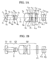
- FIGS. 1A and 1B are cross sections for an objective optical system according to an embodiment 1 according to the present invention.
- FIG. 1A is a cross section at the wide-angle end.
- FIG. 1B is a cross section at the telephoto end.
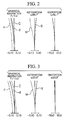
- FIG. 2 is an aberration curve at the wide-angle end in the objective optical system according to the embodiment 1 according to the present invention.
- FIG. 3 is an aberration curve at the telephoto end in the objective optical system according to the embodiment 1 according to the present invention.
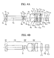
- FIGS. 4A and 4B are cross sections for an objective optical system according to an embodiment 2 according to the present invention.
- FIG. 4A is a cross section at the wide-angle end.
- FIG. 4B is a cross section at the telephoto end.
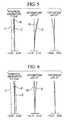
- FIG. 5 is an aberration curve at the wide-angle end in the objective optical system according to the embodiment 2 according to the present invention.
- FIG. 6 is an aberration curve at the telephoto end in the objective optical system according to the embodiment 2 according to the present invention.
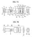
- FIGS. 7A and 7B are cross sections for an objective optical system according to an embodiment 3 according to the present invention.
- FIG. 7A is a cross section at the wide-angle end.
- FIG. 7B is a cross section at the telephoto end.
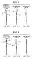
- FIG. 8 is an aberration curve at the wide-angle end in the objective optical system according to the embodiment 3 according to the present invention.
- FIG. 9 is an aberration curve at the telephoto end in the objective optical system according to the embodiment 3 according to the present invention.
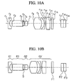
- FIGS. 10A and 10B are cross sections for an objective optical system according to an embodiment 4 according to the present invention.
- FIG. 10A is a cross section at the wide-angle end.
- FIG. 10B is a cross section at the telephoto end.
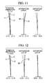
- FIG. 11 is an aberration curve at the wide-angle end in the objective optical system according to the embodiment 4 according to the present invention.
- FIG. 12 is an aberration curve at the telephoto end in the objective optical system according to the embodiment 4 according to the present invention.
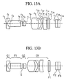
- FIGS. 13A and 13B are cross sections for an objective optical system according to an embodiment 5 according to the present invention.
- FIG. 13A is a cross section at the wide-angle end.
- FIG. 13B is a cross section at the telephoto end.
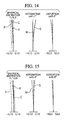
- FIG. 14 is an aberration curve at the wide-angle end in the objective optical system according to the embodiment 5 according to the present invention.
- FIG. 15 is an aberration curve at the telephoto end in the objective optical system according to the embodiment 5 according to the present invention.
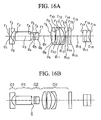
- FIGS. 16A and 16B are cross sections for an objective optical system according to an embodiment 6 according to the present invention.
- FIG. 16A is a cross section at the wide-angle end.
- FIG. 16B is a cross section at the telephoto end.
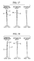
- FIG. 17 is an aberration curve at the wide-angle end in the objective optical system according to the embodiment 6 according to the present invention.
- FIG. 18 is an aberration curve at the telephoto end in the objective optical system according to the embodiment 6 according to the present invention.
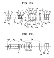
- FIGS. 19A and 19B are cross sections for an objective optical system according to an embodiment 7 according to the present invention.
- FIG. 19A is a cross section at the wide-angle end.
- FIG. 19B is a cross section at the telephoto end.
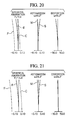
- FIG. 20 is an aberration curve at the wide-angle end in the objective optical system according to the embodiment 7 according to the present invention.
- FIG. 21 is an aberration curve at the telephoto end in the objective optical system according to the embodiment 7 according to the present invention.
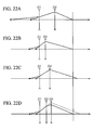
- FIGS. 22A to 22 D are view for explaining a method for adjusting positions for images by using the first lens group, the second lens group, and the moving lens group in the objective optical system according to the present invention.
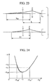
- FIG. 23 is a view for explaining a relationship between a position to an object and the focal length.
- FIG. 24 is a view for explaining a relationship between a magnification of the objective optical system and the position to an object.
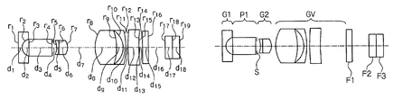
- radius of curvature is indicated by r 1 , r 2 , . . . .
- Thickness of each lens and interval of lenses are indicated by d 1 , d 2 , . . . .
- Refractive indices for each lens are indicated by n 1 , n 2 , . . . .
- Abbe number is indicated by v 1 , v 2 , . . . .
- a distance to an object is indicated by D 0 .
- a unit for length is indicated by mm in data.
- FIGS. 1A and 1B A structure for an example 1 is shown in FIGS. 1A and 1B .
- a wide-angle end is shown in FIG. 1A.
- a telephoto end is shown in FIG. 1 B.
- This example is formed by a first lens group G 1 which has a negative refractive power, an optical axis direction converting element P 1 , a second lens group G 2 which has a positive refractive power, and a moving lens group GV which has a positive refractive power such that the first lens group is disposed nearest to the object and the moving lens group GV is disposed the farthest from the object.
- the first lens group G 1 is formed by a negative single lens.
- the second lens group G 2 is formed by a cemented lens which is formed by a negative lens and a positive lens such that the negative lens is disposed nearest to the object and the positive lens is disposed the farthest from the object.
- the moving lens group GV is formed by a positive single lens, a negative single lens, and a positive single lens such that the positive single lens is disposed nearest to the object and the positive single lens is disposed farthest from the object.
- a filter F 1 which is disposed therebehind serves for cutting an infra-red range.
- F 2 to F 3 indicate filters, etc., which are disposed in front of an image-capturing surface of the image-capturing element.
- the diaphragm S is disposed behind the optical axis direction converting element.
- FIGS. 2 and 3 show aberrations at the wide-angle end and the telephoto end under such conditions. It is understood that aberrations are corrected desirably.
- FIGS. 4A and 4B A structure for an example 2 is shown in FIGS. 4A and 4B .
- a wide-angle end is shown in FIG. 4A.
- a telephoto end is shown in FIG. 4 B.
- Basic structure for lenses are the same as that in the example 1.
- FIGS. 5 and 6 show aberrations at the wide-angle end and the telephoto end under such conditions. It is understood that aberrations are corrected desirably.
- FIGS. 7A and 7B A structure for an example 3 is shown in FIGS. 7A and 7B .
- a wide-angle end is shown in FIG. 7A.
- a telephoto end is shown in FIG. 7 B.
- Basic structure for lenses are the same as that in the example 1.
- FIGS. 8 and 9 show aberrations at the wide-angle end and the telephoto end under such conditions. It is understood that aberrations are corrected desirably.
- FIGS. 10A and 10B A structure for an example 4 is shown in FIGS. 10A and 10B .
- a wide-angle end is shown in FIG. 10A.
- a telephoto end is shown in FIG. 10 B.
- Basic structure for lenses are the same as that in the example 1.
- FIGS. 11 and 12 show aberrations at the wide-angle end and the telephoto end under such conditions. It is understood that aberrations are corrected desirably.
- FIGS. 13A and 13B A structure for an example 5 is shown in FIGS. 13A and 13B .
- a wide-angle end is shown in FIG. 13A.
- a telephoto end is shown in FIG. 13 B.
- Basic structure for lenses are the same as that in the example 1.
- FIGS. 14 and 15 show aberrations at the wide-angle end and the telephoto end under such conditions. It is understood that aberrations are corrected desirably.
- FIGS. 16A and 16B A structure for an example 6 is shown in FIGS. 16A and 16B .
- a wide-angle end is shown in FIG. 16A.
- a telephoto end is shown in FIG. 16 B.
- Basic structure for lenses are the same as that in the example 1.
- FIGS. 17 and 18 show aberrations at the wide-angle end and the telephoto end under such conditions. It is understood that aberrations are corrected desirably.
- FIGS. 19A and 19B A structure for an example 7 is shown in FIGS. 19A and 19B .
- a wide-angle end is shown in FIG. 19A.
- a telephoto end is shown in FIG. 19 B.
- Basic structure for lenses are the same as that in the example 1.
- FIGS. 20 and 21 show aberrations at the wide-angle end and the telephoto end under such conditions. It is understood that aberrations are corrected desirably.
- the D L /f W is smaller than 2, it is not possible to secure a space for containing a frame in which the optical axis direction converting element and the diaphragm of which diameters are small therearound. Also, if the D L /f W is greater than 6, an unnecessary space exists which exceeds the above space. Therefore, an entire length of the optical system is long unnecessarily. Furthermore, a diameter of the second lens group is great undesirably.
- the position of the front principal point of the movable lens is disposed approximately the same position as the end surface near an object of the moving lens group or frontmore there. Therefore, a magnification at the telephoto end is great.
- an entire moving lens group in the objective optical system according to the present invention has a positive refractive power so as to increase the magnification at the telephoto end such that the first lens group has a negative refractive power and the second lens group has a positive refractive power.
- a position of the front principal point of the moving lens group is disposed approximately the same as the end surface near an object or frontmore there.
- D VH /f W is smaller than ⁇ 2
- the negative refractive power in the moving lens group is too great; thus, a back focus is long. Therefore, an entire length of the optical system is long.
- D VH /f W is greater than 0.37, it is difficult to increase the magnification at the telephoto end.
- FIGS. 22A to 22 D a method for adjusting a position of an image by using the first lens group, the second lens group, and the moving lens group in the objective optical system according to the present invention is explained with reference to FIGS. 22A to 22 D.
- the moving lens group GV is moved from the wide-angle end for a distant object which is shown in FIG. 22A to the telephoto end for a close object which is shown in FIG. 22B according to the position of the object point in the objective optical system which is formed by the first lens group G 1 which has a negative refractive power, the moving lens group GV which moves on the optical axis.
- a second lens group G 2 which has a positive refractive power is disposed between the first lens group G 1 and the moving lens group GV.
- the focal length f V of the moving lens group satisfies a condition such as 2.5 ⁇ f V /f W ⁇ 4; therefore, the entire length of the objective optical system is shortened while obtaining a magnification at the telephoto end.
- f V /f W is smaller than 2.5, a back focus is too short to obtain an interval for adjusting a focus sufficiently.
- f V /f W is greater than 4, an entire length of the objective optical system is long.
- the magnification ⁇ VT in an telephoto end of the moving lens group satisfies a condition such as ⁇ 1.2 ⁇ VT ⁇ 0.83. By doing this, an optical magnification can be obtained at the telephoto end to which the distance to the object is the closest.
- magnification ⁇ VT is smaller than ⁇ 1.2, the distance to the object is more separated; thus, it is not possible to realize a magnification in an entire system. Also, if the magnification ⁇ VT is greater than ⁇ 0.83, the magnification at the telephoto end of the moving lens group is small; thus, it is not possible to obtain a magnification in an entire system.
- reference numeral 1 indicates a negative lens system as a front group and reference numeral 2 indicates a positive lens group as a rear group.
- F indicates a focal length of an entire system
- F 1 indicates a focal length of a negative lens system as a front group
- F 2 indicates a focal length of a positive lens system as a rear group
- ⁇ 1 ′ indicates a magnification of a negative lens system as a front group for an observation at a wide-angle end
- ⁇ 2 ′ indicates a magnification of a positive lens system as a rear group
- L indicates a distance between the negative lens system as a front group and a position of a focal point at a rear end of the entire system
- F and L can be represented by formulae (1) and (2) as follows.
- F F 1 ⁇ 2 ′
- L F 1 (1 ⁇ 1 ′)+ F 2 (2 ⁇ 2 ′ ⁇ 1/ ⁇ 2 ′) (2)
- the focal length F varies according to the formula (1).
- the entire length L varies according to the formula (2).
- a distance between the position of the focal point in a front position of the negative lens system as a front group which has a random ⁇ 2 ′ and the object point is indicated by x, it is possible to determine x under condition that ⁇ 2 ′ is varied by setting ⁇ 2 ′ under a specific condition and moving the positive lens system as a rear group under such a condition.
- x [( F 2 /F 1 2 )( ⁇ 2w ′+1/ ⁇ 2w ′ ⁇ 2 ′ ⁇ 1/ ⁇ 2 ′)+1/ x w ] ⁇ 1 (3)
- x OW can be determined by a formula (4) below.
- x Ow [1/ xw+[F 2 / F 12 ][2+ ⁇ 2 w′+ 1/ ⁇ 2 w ′] ⁇ 1 (4)
- FIG. 24 is a graph which shows a relationship which is indicated by the formula (4).
- a vertical axis is indicated by ⁇ x
- a horizontal axis is indicated by ⁇ 2 ′.
- the moving lens group is provided with a lens which has at least a positive refractive power and a lens which has a negative refractive power in an order such that the lens which has the positive refractive power is disposed nearest to the tip section. Therefore, the moving lens group is disposed in an approximate telephoto manner; thus, the position of the front principal point is fed forwardly. Thus, it is possible to realize a high magnification at the telephoto end.
- the moving lens group has another lens which has a positive refractive power between the lens which has positive refractive power and the lens which has negative refractive power. Therefore, in a structural point of view, the moving lens group is disposed in an approximate telephoto manner such that the position of the front principal point is fed forwardly. Simultaneously, it is possible to disperse the refractive power by two lenses which has a positive refractive power. Thus, it is possible to increase a flexibility in a lens design for correcting aberrations.
- the air-converged length D A (mm) from the end surface near an image of the first lens group to a position of the diaphragm satisfies a condition such as 1.674 (mm) ⁇ D A ⁇ 4 (mm). Therefore, a space in which the optical axis direction converting element is inserted is obtained.
- the image-capturing element such as a CCD can be downsized. Thus, even if a height of an image in the image-capturing element is small, the optical axis of that lens which has the positive refractive power is bent by the optical axis direction converting element so as to be formed inside of the endoscope.
- D A (mm) is smaller than 1.674 (mm)
- D A (mm) is greater than 4 (mm)
- an excessive space is obtained in a space in which the optical axis direction converting element is inserted; thus, such an excessive space affects a specification for an outer shape of the endoscope undesirably.
- a focal length f T (mm) in an entire system at a telephoto end satisfies a condition such as 2(1/mm) ⁇ D L /(f W ⁇ f T ) ⁇ 4(1/mm). Therefore, the first lens group and the moving lens group approach with each other at the telephoto end; thus, the focal length in an entire system at the telephoto end is great. Therefore, it is possible to obtain a greater magnification more easily.
- D L /(f W ⁇ f T )(1/mm) is smaller than 2(1/mm)
- D L /(f W ⁇ f T )(1/mm) is smaller than 2(1/mm)
- D L /(f W ⁇ f T )(1/mm) is greater than 4(1/mm), it is not possible to obtain a magnification at the telephoto end.
- an infra-red-ray-cutting filter may be disposed between the diaphragm and the moving lens group.
- An infra-red-ray-cutting filter is disposed between the diaphragm and the moving lens group; thus, an infra-red ray can be blocked while shortening an entire length of the objective optical system.
- a prism may be disposed between the first lens group and the diaphragm.
- a prism is disposed between the first lens group and the diaphragm.
- back focus between the end surface near an image in the first lens group and the end surface near an object in the movable lens group is indicated by D L (mm)
- a focal length in an entire system at the wide-angle end is indicated by f W (mm)
- a distance between the end surface near an object in the movable lens group and the front principal point is indicated by D VH (mm); thus, a condition such as 2 ⁇ D L /f W ⁇ 6 is satisfied. Therefore, a sufficient distance is obtained at the telephoto end in which a distance between the first lens group and the movable lens group.
- an optical axis direction converting element is disposed even at the telephoto end of the movable lens group; thus, a sufficient distance can be realized even in a small frame in which a diameter near the diaphragm is small. Therefore, it is possible to obtain a high magnification while a sufficient distance is realized between the diaphragm which is disposed behind the perspective-converting optical element such as a prism and the moving lens group.
- the focal length f V (mm) of the moving lens group satisfies a condition such as 2.5 ⁇ f V /f W ⁇ 4.
- a magnification ⁇ VT in an telephoto end of the moving lens group satisfies a condition such as ⁇ 1.2 ⁇ VT ⁇ 0.83.
- a sufficient optical magnification can be obtained at the telephoto end to which the distance to the object is the closest. Therefore, it is possible to obtain a high magnification while a sufficient distance is realized between the diaphragm which is disposed behind the perspective-converting optical element such as a prism and the moving lens group.
- the moving lens group is provided with, in an order from nearer the object, a lens which has at least a positive refractive power and a lens which has a negative refractive power.
- the moving lens group has another lens which has a positive refractive power between the lens which has positive refractive power and the lens which has negative refractive power.
- the moving lens group has another lens which has a positive refractive power between the lens which has positive refractive power and the lens which has negative refractive power. Therefore, in a structural point of view, the moving lens group is disposed in an approximate telephoto manner such that the position of the front principal point is fed forwardly. Simultaneously, it is possible to disperse the refractive power by two lenses which has a positive refractive power.
- the air-converged length D A (mm) from the end surface near an image of the first lens group to a position of the diaphragm satisfies a condition such as 1.674 (mm) ⁇ D A ⁇ 4 (mm). Therefore, a space in which the optical axis direction converting element is inserted is obtained.
- the image-capturing element such as a CCD can be downsized.
- the optical axis of that lens which has the positive refractive power is bent by the optical axis direction converting element so as to be formed inside of the endoscope. Therefore, it is possible to obtain a high magnification while realizing a sufficient distance between the diaphragm which is disposed behind the perspective-converting optical element and the moving lens group.
- an infra-red-ray-cutting filter is disposed between the diaphragm and the moving lens group.
- a focal length f T (mm) in an entire system at a telephoto end satisfies a condition such as 2(1/mm) ⁇ D L /(f W /f T ) ⁇ 4(1/mm). Therefore, the first lens group and the moving lens group approach with each other at the telephoto end; thus, the focal length in an entire system at the telephoto end is great. Therefore, it is possible to obtain a greater magnification more easily. Therefore, it is possible to obtain a high magnification while realizing a sufficient distance between the diaphragm which is disposed behind the perspective-converting optical element such as a prism and the moving lens group.
- a prism is disposed between the first lens group and the diaphragm.
Landscapes
- Physics & Mathematics (AREA)
- General Physics & Mathematics (AREA)
- Optics & Photonics (AREA)
- Lenses (AREA)
Applications Claiming Priority (2)
| Application Number | Priority Date | Filing Date | Title |
|---|---|---|---|
| JPPAT.2003-192235 | 2003-07-04 | ||
| JP2003192235A JP4383107B2 (ja) | 2003-07-04 | 2003-07-04 | 対物光学系 |
Publications (2)
| Publication Number | Publication Date |
|---|---|
| US20050030639A1 US20050030639A1 (en) | 2005-02-10 |
| US6943959B2 true US6943959B2 (en) | 2005-09-13 |
Family
ID=34113570
Family Applications (1)
| Application Number | Title | Priority Date | Filing Date |
|---|---|---|---|
| US10/879,086 Expired - Lifetime US6943959B2 (en) | 2003-07-04 | 2004-06-30 | Objective optical system |
Country Status (2)
| Country | Link |
|---|---|
| US (1) | US6943959B2 (ja) |
| JP (1) | JP4383107B2 (ja) |
Cited By (20)
| Publication number | Priority date | Publication date | Assignee | Title |
|---|---|---|---|---|
| US20070115560A1 (en) * | 2005-11-18 | 2007-05-24 | Taro Kushida | Zoom lens and camera |
| US20070206293A1 (en) * | 2006-03-01 | 2007-09-06 | Hideyasu Takato | Magnifying optical system for endoscope |
| US7846107B2 (en) | 2005-05-13 | 2010-12-07 | Boston Scientific Scimed, Inc. | Endoscopic apparatus with integrated multiple biopsy device |
| US7955255B2 (en) | 2006-04-20 | 2011-06-07 | Boston Scientific Scimed, Inc. | Imaging assembly with transparent distal cap |
| US7967759B2 (en) | 2006-01-19 | 2011-06-28 | Boston Scientific Scimed, Inc. | Endoscopic system with integrated patient respiratory status indicator |
| US8052597B2 (en) | 2005-08-30 | 2011-11-08 | Boston Scientific Scimed, Inc. | Method for forming an endoscope articulation joint |
| US8083671B2 (en) | 2004-09-30 | 2011-12-27 | Boston Scientific Scimed, Inc. | Fluid delivery system for use with an endoscope |
| US8097003B2 (en) | 2005-05-13 | 2012-01-17 | Boston Scientific Scimed, Inc. | Endoscopic apparatus with integrated variceal ligation device |
| US8118732B2 (en) | 2003-04-01 | 2012-02-21 | Boston Scientific Scimed, Inc. | Force feedback control system for video endoscope |
| US8197400B2 (en) | 2004-09-30 | 2012-06-12 | Boston Scientific Scimed, Inc. | Selectively rotatable shaft coupler |
| US8199187B2 (en) | 2004-09-30 | 2012-06-12 | Boston Scientific Scimed, Inc. | Adapter for use with digital imaging medical device |
| US8202265B2 (en) | 2006-04-20 | 2012-06-19 | Boston Scientific Scimed, Inc. | Multiple lumen assembly for use in endoscopes or other medical devices |
| US8353860B2 (en) | 2004-09-30 | 2013-01-15 | Boston Scientific Scimed, Inc. | Device for obstruction removal with specific tip structure |
| US8357148B2 (en) | 2004-09-30 | 2013-01-22 | Boston Scientific Scimed, Inc. | Multi-functional endoscopic system for use in electrosurgical applications |
| US8425408B2 (en) | 2003-04-01 | 2013-04-23 | Boston Scientific Scimed, Inc. | Articulation joint for video endoscope |
| US8435172B2 (en) | 2004-09-30 | 2013-05-07 | Boston Scientific Scimed, Inc. | Automated control of irrigation and aspiration in a single-use endoscope |
| US8475366B2 (en) | 2003-04-01 | 2013-07-02 | Boston Scientific Scimed, Inc. | Articulation joint for a medical device |
| US8535219B2 (en) | 2003-04-01 | 2013-09-17 | Boston Scientific Scimed, Inc. | Fluid manifold for endoscope system |
| US8622894B2 (en) | 2003-04-01 | 2014-01-07 | Boston Scientific Scimed, Inc. | Articulation joint |
| US8888684B2 (en) | 2006-03-27 | 2014-11-18 | Boston Scientific Scimed, Inc. | Medical devices with local drug delivery capabilities |
Families Citing this family (6)
| Publication number | Priority date | Publication date | Assignee | Title |
|---|---|---|---|---|
| JP4814746B2 (ja) * | 2006-09-27 | 2011-11-16 | オリンパスメディカルシステムズ株式会社 | 内視鏡対物光学系 |
| CN203894464U (zh) | 2011-09-29 | 2014-10-22 | 富士胶片株式会社 | 成像镜头和成像设备 |
| JP2013073156A (ja) * | 2011-09-29 | 2013-04-22 | Fujifilm Corp | 撮像レンズおよび撮像装置 |
| JP2013073149A (ja) * | 2011-09-29 | 2013-04-22 | Fujifilm Corp | 撮像レンズおよび撮像装置 |
| JP6257853B2 (ja) * | 2015-10-20 | 2018-01-10 | オリンパス株式会社 | 内視鏡 |
| JP2017173347A (ja) * | 2016-03-18 | 2017-09-28 | 富士フイルム株式会社 | 撮像レンズおよび撮像装置 |
Citations (3)
| Publication number | Priority date | Publication date | Assignee | Title |
|---|---|---|---|---|
| JPS5162053A (ja) | 1974-11-27 | 1976-05-29 | Olympus Optical Co | |
| JPH01279219A (ja) | 1988-05-02 | 1989-11-09 | Olympus Optical Co Ltd | 内視鏡対物レンズ |
| US6160669A (en) * | 1996-04-15 | 2000-12-12 | Olympus Optical Co., Ltd. | Lens system |
-
2003
- 2003-07-04 JP JP2003192235A patent/JP4383107B2/ja not_active Expired - Fee Related
-
2004
- 2004-06-30 US US10/879,086 patent/US6943959B2/en not_active Expired - Lifetime
Patent Citations (3)
| Publication number | Priority date | Publication date | Assignee | Title |
|---|---|---|---|---|
| JPS5162053A (ja) | 1974-11-27 | 1976-05-29 | Olympus Optical Co | |
| JPH01279219A (ja) | 1988-05-02 | 1989-11-09 | Olympus Optical Co Ltd | 内視鏡対物レンズ |
| US6160669A (en) * | 1996-04-15 | 2000-12-12 | Olympus Optical Co., Ltd. | Lens system |
Cited By (34)
| Publication number | Priority date | Publication date | Assignee | Title |
|---|---|---|---|---|
| US8118732B2 (en) | 2003-04-01 | 2012-02-21 | Boston Scientific Scimed, Inc. | Force feedback control system for video endoscope |
| US11324395B2 (en) | 2003-04-01 | 2022-05-10 | Boston Scientific Scimed, Inc. | Endoscopic imaging system |
| US10765307B2 (en) | 2003-04-01 | 2020-09-08 | Boston Scientific Scimed, Inc. | Endoscopic imaging system |
| US9913573B2 (en) | 2003-04-01 | 2018-03-13 | Boston Scientific Scimed, Inc. | Endoscopic imaging system |
| US8622894B2 (en) | 2003-04-01 | 2014-01-07 | Boston Scientific Scimed, Inc. | Articulation joint |
| US8608648B2 (en) | 2003-04-01 | 2013-12-17 | Boston Scientific Scimed, Inc. | Articulation joint |
| US8535219B2 (en) | 2003-04-01 | 2013-09-17 | Boston Scientific Scimed, Inc. | Fluid manifold for endoscope system |
| US8475366B2 (en) | 2003-04-01 | 2013-07-02 | Boston Scientific Scimed, Inc. | Articulation joint for a medical device |
| US8425408B2 (en) | 2003-04-01 | 2013-04-23 | Boston Scientific Scimed, Inc. | Articulation joint for video endoscope |
| US8083671B2 (en) | 2004-09-30 | 2011-12-27 | Boston Scientific Scimed, Inc. | Fluid delivery system for use with an endoscope |
| US8197400B2 (en) | 2004-09-30 | 2012-06-12 | Boston Scientific Scimed, Inc. | Selectively rotatable shaft coupler |
| US8199187B2 (en) | 2004-09-30 | 2012-06-12 | Boston Scientific Scimed, Inc. | Adapter for use with digital imaging medical device |
| USRE46007E1 (en) | 2004-09-30 | 2016-05-24 | Boston Scientific Scimed, Inc. | Automated control of irrigation and aspiration in a single-use endoscope |
| US8353860B2 (en) | 2004-09-30 | 2013-01-15 | Boston Scientific Scimed, Inc. | Device for obstruction removal with specific tip structure |
| US8357148B2 (en) | 2004-09-30 | 2013-01-22 | Boston Scientific Scimed, Inc. | Multi-functional endoscopic system for use in electrosurgical applications |
| US8435172B2 (en) | 2004-09-30 | 2013-05-07 | Boston Scientific Scimed, Inc. | Automated control of irrigation and aspiration in a single-use endoscope |
| US8585715B2 (en) | 2005-05-13 | 2013-11-19 | Boston Scientific Scimed, Inc. | Endoscopic apparatus with integrated variceal ligation device |
| US8097003B2 (en) | 2005-05-13 | 2012-01-17 | Boston Scientific Scimed, Inc. | Endoscopic apparatus with integrated variceal ligation device |
| US7846107B2 (en) | 2005-05-13 | 2010-12-07 | Boston Scientific Scimed, Inc. | Endoscopic apparatus with integrated multiple biopsy device |
| US11957312B2 (en) | 2005-08-30 | 2024-04-16 | Boston Scientific Scimed, Inc. | Method for forming an endoscope articulation joint |
| US11191424B2 (en) | 2005-08-30 | 2021-12-07 | Boston Scientific Scimed, Inc. | Method for forming an endoscope articulation joint |
| US10052013B2 (en) | 2005-08-30 | 2018-08-21 | Boston Scientific Scimed, Inc. | Medical device comprising segments |
| US8052597B2 (en) | 2005-08-30 | 2011-11-08 | Boston Scientific Scimed, Inc. | Method for forming an endoscope articulation joint |
| US9439557B2 (en) | 2005-08-30 | 2016-09-13 | Boston Scientific Scimed, Inc. | Articulation joint |
| US20070115560A1 (en) * | 2005-11-18 | 2007-05-24 | Taro Kushida | Zoom lens and camera |
| US7274516B2 (en) * | 2005-11-18 | 2007-09-25 | Eastman Kodak Company | Zoom lens and camera |
| US7967759B2 (en) | 2006-01-19 | 2011-06-28 | Boston Scientific Scimed, Inc. | Endoscopic system with integrated patient respiratory status indicator |
| US7499226B2 (en) * | 2006-03-01 | 2009-03-03 | Olympus Medical Systems Corp. | Magnifying optical system for endoscope |
| US20070206293A1 (en) * | 2006-03-01 | 2007-09-06 | Hideyasu Takato | Magnifying optical system for endoscope |
| US8888684B2 (en) | 2006-03-27 | 2014-11-18 | Boston Scientific Scimed, Inc. | Medical devices with local drug delivery capabilities |
| US9358363B2 (en) | 2006-04-20 | 2016-06-07 | Boston Scientific Scimed, Inc. | Multiple lumen assembly for use in endoscopes or other medical devices |
| US8870753B2 (en) | 2006-04-20 | 2014-10-28 | Boston Scientific Scimed, Inc. | Imaging assembly with transparent distal cap |
| US7955255B2 (en) | 2006-04-20 | 2011-06-07 | Boston Scientific Scimed, Inc. | Imaging assembly with transparent distal cap |
| US8202265B2 (en) | 2006-04-20 | 2012-06-19 | Boston Scientific Scimed, Inc. | Multiple lumen assembly for use in endoscopes or other medical devices |
Also Published As
| Publication number | Publication date |
|---|---|
| JP4383107B2 (ja) | 2009-12-16 |
| US20050030639A1 (en) | 2005-02-10 |
| JP2005025059A (ja) | 2005-01-27 |
Similar Documents
| Publication | Publication Date | Title |
|---|---|---|
| US6943959B2 (en) | Objective optical system | |
| CN107076967B (zh) | 内窥镜用变倍光学系统及内窥镜 | |
| JP2804267B2 (ja) | 内視鏡対物レンズ | |
| JP2697822B2 (ja) | 内視鏡対物レンズ | |
| US8164836B2 (en) | Objective lens for endoscopes | |
| JP2876252B2 (ja) | 内視鏡対物レンズ | |
| JP3606548B2 (ja) | 3群ズームレンズ | |
| US6751030B2 (en) | Zoom lens and image-taking apparatus | |
| US7538953B2 (en) | Zoom lens system | |
| US20200348495A1 (en) | Zoom lens and image pickup apparatus having the same | |
| JP5567225B2 (ja) | 内視鏡用対物レンズおよび内視鏡 | |
| JP2003140041A (ja) | ズームレンズ系 | |
| US6633437B1 (en) | Zoom lens and photographing apparatus having it | |
| JP6503383B2 (ja) | ズーム撮像装置 | |
| JP4999571B2 (ja) | 変倍ファインダーおよびそれを用いた撮像装置 | |
| JP4426236B2 (ja) | 内視鏡対物光学系 | |
| JP4585796B2 (ja) | ズームレンズ及びそれを有する撮像装置 | |
| CN111630429B (zh) | 内窥镜用变倍光学系统及内窥镜 | |
| JP4394197B2 (ja) | 内視鏡対物変倍光学系 | |
| JPH0648328B2 (ja) | アフオ−カルズ−ムレンズ | |
| JP2004184825A (ja) | ズーム結像レンズ及びそれを用いた顕微鏡 | |
| JP4516291B2 (ja) | ズームレンズ及びそれを用いたカメラ。 | |
| JPH06102453A (ja) | 小型の実像式変倍ファインダー | |
| WO2023012866A1 (ja) | 内視鏡用対物光学系、撮像ユニット、及び内視鏡 | |
| JP4131034B2 (ja) | ズームレンズ及び撮像装置 |
Legal Events
| Date | Code | Title | Description |
|---|---|---|---|
| AS | Assignment |
Owner name: OLYMPUS CORPORATION, JAPAN Free format text: ASSIGNMENT OF ASSIGNORS INTEREST;ASSIGNOR:HOMMA, HIROYUKI;REEL/FRAME:015898/0637 Effective date: 20040701 |
|
| FEPP | Fee payment procedure |
Free format text: PAYOR NUMBER ASSIGNED (ORIGINAL EVENT CODE: ASPN); ENTITY STATUS OF PATENT OWNER: LARGE ENTITY |
|
| STCF | Information on status: patent grant |
Free format text: PATENTED CASE |
|
| FPAY | Fee payment |
Year of fee payment: 4 |
|
| FPAY | Fee payment |
Year of fee payment: 8 |
|
| AS | Assignment |
Owner name: OLYMPUS CORPORATION, JAPAN Free format text: CHANGE OF ADDRESS;ASSIGNOR:OLYMPUS CORPORATION;REEL/FRAME:039344/0502 Effective date: 20160401 |
|
| FPAY | Fee payment |
Year of fee payment: 12 |