US6939291B2 - Endoscopic device for locomotion through the gastro-intestinal tract - Google Patents
Endoscopic device for locomotion through the gastro-intestinal tract Download PDFInfo
- Publication number
- US6939291B2 US6939291B2 US10/469,340 US46934003A US6939291B2 US 6939291 B2 US6939291 B2 US 6939291B2 US 46934003 A US46934003 A US 46934003A US 6939291 B2 US6939291 B2 US 6939291B2
- Authority
- US
- United States
- Prior art keywords
- clamping means
- endoscopic device
- intermediate section
- end section
- jaw
- Prior art date
- Legal status (The legal status is an assumption and is not a legal conclusion. Google has not performed a legal analysis and makes no representation as to the accuracy of the status listed.)
- Expired - Lifetime, expires
Links
Images


Classifications
-
- A—HUMAN NECESSITIES
- A61—MEDICAL OR VETERINARY SCIENCE; HYGIENE
- A61B—DIAGNOSIS; SURGERY; IDENTIFICATION
- A61B1/00—Instruments for performing medical examinations of the interior of cavities or tubes of the body by visual or photographical inspection, e.g. endoscopes; Illuminating arrangements therefor
- A61B1/00147—Holding or positioning arrangements
- A61B1/00151—Holding or positioning arrangements using everted tubes
-
- A—HUMAN NECESSITIES
- A61—MEDICAL OR VETERINARY SCIENCE; HYGIENE
- A61B—DIAGNOSIS; SURGERY; IDENTIFICATION
- A61B1/00—Instruments for performing medical examinations of the interior of cavities or tubes of the body by visual or photographical inspection, e.g. endoscopes; Illuminating arrangements therefor
- A61B1/012—Instruments for performing medical examinations of the interior of cavities or tubes of the body by visual or photographical inspection, e.g. endoscopes; Illuminating arrangements therefor characterised by internal passages or accessories therefor
- A61B1/015—Control of fluid supply or evacuation
-
- A—HUMAN NECESSITIES
- A61—MEDICAL OR VETERINARY SCIENCE; HYGIENE
- A61M—DEVICES FOR INTRODUCING MEDIA INTO, OR ONTO, THE BODY; DEVICES FOR TRANSDUCING BODY MEDIA OR FOR TAKING MEDIA FROM THE BODY; DEVICES FOR PRODUCING OR ENDING SLEEP OR STUPOR
- A61M25/00—Catheters; Hollow probes
- A61M25/01—Introducing, guiding, advancing, emplacing or holding catheters
- A61M25/0105—Steering means as part of the catheter or advancing means; Markers for positioning
- A61M25/0116—Steering means as part of the catheter or advancing means; Markers for positioning self-propelled, e.g. autonomous robots
Definitions
- the present invention relates to an endoscopic device for locomotion through a tubular body cavity, in particular, but not exclusively, through the gastrointestinal tract, able to migrate in a prefixed direction with so-called inchworm motion.
- Endoscopic devices for surgical or diagnostic procedure are already known. These devices are operated by the surgeon who directly imparts to the device the forward motion through the patient's body. Surgical and/or diagnostic instruments which are necessary to carry out each specific procedure, such as microarms, microcameras, and/or laser emitters are generally associated to these devices.
- the object of the present invention is to provide an endoscopic device of the semi-autonomous locomotion type through a body cavity such as the gastro-intestinal tract, capable of assuring a suitable anchorage to the body cavity thereby allowing its advancement through it, without giving rise to any of the problems encountered with the similar known devices.
- Another object of the present invention is to provide an endoscopic device of the above mentioned type for achieving a suitable anchorage to the cavity wall by means of structurally simple solutions allowing the size of the device to be kept small.
- the endoscopic device for locomotion in a body cavity in a prefixed advancement direction comprising at least a variable length intermediate section extending between a front end section and a rear end section with respect to said direction and first and second clamping means integral to the front end section and, respectively, the rear end section, for selectively grasping respective surrounding portions of the wall of the body cavity.
- first and second clamping means Associated to the first and second clamping means suction means are provided for creating a vacuum sufficient to cause the surrounding portions of the body cavity walls to collapse within the first and the second clamping means, when they are in their open condition, to allow a firm grasping when said clamping means are closed.
- Means for operating alternate elongations and retractions of the intermediate section and means for operating the first and second clamping means synchronously operated to cause an advancement of the rear end section device in the prefixed direction following a retraction of the intermediate section when the respective portion of surrounding wall is firmly engaged with the first clamping means, and to cause an advancement of the front end section in the same direction following an elongation of the intermediate section when the respective surrounding wall portion is firmly engaged within the second clamping means.
- the present invention provides a method for producing the locomotion through body cavities of an endoscopic device, by means of successive extensions and retractions of at least one variable length intermediate section thereof according a prefixed direction defining front end section and a rear end section of the device, to which first and second clamping means are respectively associated selectively operable from the outside synchronously with the successive extensions and retractions of the intermediate section.
- the method is characterized by inducing selectively by suction a pneumatic depression in correspondence to one of the first or the second clamping means in their open condition, the depression being such that to cause the surrounding portion of body cavity wall to collapse within said clamping means, and closing said clamping means to grasp said surrounding wall portion and firmly anchoring to it the respective end section to allow the free movement of the other end section in the prefixed direction.
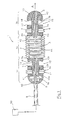
- FIG. 1 is a longitudinal sectional view of a first embodiment of the endoscopic device according to the present invention
- FIGS. 2 a - 2 k show and advancement cycle of the device of FIG. 1 ;
- FIG. 3 is a longitudinal sectional view of a second embodiment of the device according to the present invention.
- FIG. 4 is a cross sectional view of the endoscopic device of FIG. 3 taken along arrows IV—IV;
- FIG. 5 is a longitudinal sectional view of the endoscopic device of FIG. 3 taken along arrows V—V of FIG. 4 ;
- FIGS. 6 a , 6 b , 6 c schematically show the operation of the clamping means integral to the rear end of the endoscopic device of FIG. 3 ;
- FIGS. 7 a , 7 b schematically show the operation of the clamping means integral to the front end of the endoscopic device of FIG. 3 ;
- FIGS. 8 a - 8 g show and advancement cycle of the endoscopic device according to FIG. 3 .
- FIG. 1 it has been generally indicated at 1 an endoscopic device according to the present invention. It comprises an intermediate section 1 a of a tubular shape, extending between two end sections called front end section 1 b and rear end section 1 c , the terms “front” and “rear” being referred to a reference direction indicated at A.
- the tubular intermediate section 1 a is formed by a wall 2 made of elastic and flexible material shaped like a bellows and delimiting a cavity 3 for containing a fluid, for example air.
- the intermediate section ends with a front flange 2 a and a rear flange 2 b through which it is connected to front end section 1 b and rear end section 1 c respectively.
- Front end section 1 b of the device is formed by a stem 4 fixed to front flange 2 a at a flanged end 4 a thereof and to a front head 5 of the device at the other end.
- a bellows member 6 Fixed to flanged end 4 a of stem 4 , at the opposite side of flange 2 a , is a bellows member 6 which is integral to a jaw 7 a of a first clamp 7 (also called front clamp) slidably mounted on stem 4 and fixed to the free end of bellows 6 .
- the other jaw 7 b of first clamp 7 is constituted by a face of front head 5 perpendicular to the axis of stem 4 and faced toward first jaw 7 a.
- Rear end section 1 c is formed by a rear head 8 , from which a tubular connector 9 extends, connected to a flanged end 10 a of a stem 10 .
- Fixed to flanged end 10 a at the opposite side of rear head 8 , is a bellows member 11 integral to a jaw 12 a of a second clamp 12 (also called rear clamp) coaxially and slidably mounted on stem 10 , the other jaw 12 b of second clamp 12 being formed by a plate fixed to the end of stem 10 at one side thereof and to rear flange 2 b of intermediate section 1 a at the other side.
- Tubular connector 9 puts into communication the device with an external control system, of the conventional type, for example as described and shown in FIG. 3 of U.S. Pat. No. 5,906,591, comprising a source ( 50 ) for selectively providing a positive or negative pressure to the various parts of the devices as will be explained below. More precisely, connector 9 houses pneumatic conduits extending in a substantially axial way within device 1 (as schematically shown in FIG.
- FIGS. 2 a - 2 k the parts being in turn under pressure are shown as hatched.
- a substantially annular portion P of the surrounding wall of the body cavity is caused to collapse between jaws 12 a, b which, by adduction of compressed air within bellows 11 , close against each other firmly grasping wall portion P ( FIG. 2 a ).
- Through radial duct 13 of stem 4 air is blown against cavity wall P to cause its displacement from front end section 1 b of the device ( FIG. 2 b ).
- compressed air is fed to bellows 2 which elongates pushing front end section 1 b of the device forward ( FIG. 2 c ).
- rear clamp 12 grasp a new annular portion of surrounding cavity wall P by creation of a depression between jaws 12 a , 12 b ( FIG. 2 i ) and closure of rear clamp 12 ( FIG. 2 j ), while front clamp 7 opens to release the grasped annular wall portion. Then the cycle is repeated with a new advancement step.
- a circular groove 17 is formed on one of their opposed faces and a corresponding step 18 for engaging with groove 17 is formed on the other face.
- all the edges of the grip surfaces are beveled to avoid any tissue damage.
- FIGS. 3 , 4 , 5 , 6 a -c and 7 a, b A second embodiment of the endoscopic device according to the invention is shown in FIGS. 3 , 4 , 5 , 6 a -c and 7 a, b .
- 21 a indicates an intermediate tubular section of the device formed by a bellows wall 22 made of elastic and flexible material delimiting a chamber 23
- 21 b indicates a front end section connected to intermediate section 21 a through a front flange 22 a
- 21 c indicates a rear end section connected to intermediate section 21 a through a rear flange 22 b.
- Front end section 21 b comprises a head 25 conected to front flange 22 a and integral to a stem 24 axially extending through intermediate section 21 a and rear end section 21 c and connected to a tubular connector 29 .
- a first clamp 27 is mounted at the end of stem 24 opposite to that where head 25 is fixed.
- Each clamp is formed by a jaw 27 a axially slidable on stem 24 and by a jaw 27 b fixedly connected thereto.
- Jaw 27 a and 27 b are each formed by a pair of jaw portions diametrically arranged on stem 24 .
- the two portions of jaw 27 a are mutually connected by means of a bracket 28 passing through a slot 30 diametrically formed in stem 24 .
- An actuating wire 26 crosses bracket 28 in two points and is fixed to the bracket at one of them while being slidable at the other one.
- Wire 26 slidably extends through the overall length of stem 24 forming a loop along it and its free ends are conveyed externally through connector 29 .
- the opening and closure of clamp 27 can be controlled, as also shown in FIGS. 7 a and 7 b.
- rear end section 21 c of the device comprises a first sleeve 33 coaxially mounted on stem 24 and slidable thereon.
- Sleeve 33 has a flanged end one side of which is fixed to rear flange 22 b of intermediate section 21 a , the other one being fixed to a bellow 31 coaxial thereto.
- a pair of arm 33 a , 33 b extend from sleeve 33 in a diametrically opposed and parallel relationship with respect to stem 24 .
- Arms 33 a , 33 b are arranged on a plane rotated of an angle of 90° with respect to the two jaw portions of first clamp 27 and support jaws 32 a and 32 b of second clamp 32 .
- first clamp 27 , second clamp 32 is formed by two diametrically opposed clamp portions and therefore clamps 27 and 32 are in a substantially crosswise arrangement with respect to the longitudinal axis of the device, as shown in FIG. 4 .
- the pair of portions of jaw 32 a are fixed to the free ends of arms 33 a and 33 b
- the pair of portions of mobile jaw 32 b are formed at the end of two further arms 34 a and 34 b extending at the outside of arms 33 a and 33 b and parallel thereto from a second sleeve 34 integral to bellow 31 and axially slidable on sleeve 33 .
- the sliding of arms 34 a, b with respect to arms 33 a, b is limited at one side by the abutment with fixed jaw 32 a and at the other side by the mutual abutment between shoulders 35 and 36 formed on the respective sliding surfaces.
- Tubular connector 29 houses a plurality of pneumatic tubes communicating to a series of conduits formed in stem 24 .
- conduits 37 and 38 are provided for creating a depression or feeding compressed air between jaws 27 a, b of first clamp 27 and jaws 32 a, b of second clamp 32 , to help engagement and, respectively, release of the surrounding wall portion P of the body cavity, and conduits 45 and 46 to suck or feed air from/to bellows 31 and 22 , thereby causing them to extend and respectively to retract.
- a conduit for feeding air to head 25 is also provided to blow air against the cavity wall during the forward motion. These conduits are all shown in FIG. 3 for sake of simplicity.
- Conduits 38 and 45 are helically arranged inside chamber 23 .
- FIGS. 8 a - 8 g The operating cycle of the endoscopic device according to the second embodiment of the invention is shown in FIGS. 8 a - 8 g .
- vacuum is created in correspondence of the jaws of second camp 32 to cause a surrounding wall portion P of the body cavity to collapse therebetween ( FIG. 8 a ), then compressed air is entered in bellows 31 which in this way is elongated causing the closure of second clamp 32 and the grasping of wall portion P ( FIG. 8 b ).
- Compressed air is entered in chamber 23 of bellows 22 which expands pushing front head 25 forward.
- front head 25 pull first clamp 27 forward ( FIG.
- first clamp 27 After having created a depression between the jaws of first clamp 27 to make the surrounding wall portion P to collapse therebetween, first clamp 27 is closed by traction of actuating wire 26 to grasp wall portion P ( FIG. 8 d ). At this point second clamp 32 can be opened by sucking air from bellow 31 , to release the wall portion P held thereby ( FIG. 8 e ). Once second clamp 32 is opened, it is made to advance with respect to first clamp 27 by sucking air from bellow 22 , which retracts ( FIG. 8 f ). In these conditions, after second clamp 32 is held again to the body cavity wall, first clamp 27 is opened and the cycle repeated for a further advancement step.
- Opposed grip surfaces of jaws of first and second clamp 27 and 32 are formed with an annular groove and a corresponding step for engaging therewith to improve the grip of the wall portion of the body cavity.
- clamps 27 and 32 alternately overtake each other during each advancement step of the device and the clamp that in turn is in the distal position is the gripping one, while the other one is free and is pulled forward. This prevents the body cavity wall, due to its easily yielding nature, from retracting into folds together with the device in the retraction step and extending in the next extension step without achieving any real forward motion of the device.
- the endoscopic device according to the invention can migrate through a body cavity of tubular shape apart from the consistency of the walls and the friction that can be afforded by them, because it is able to grasp at the cavity wall before exerting its propulsive push.
- the increased patient's comfort and the reduction of manual handling made possible with the device of the invention could promote the possibility of mass screening the population for gasto-itnestinal aliments, in particular to carry out colonoscopy and rectosigmoidoscopy, this being a particularly important inspection, in so far as about 70% of the colon cancers are localized in the first tract or the colon.
- future integration of miniaturized endoscopic tools onboard the locomotive device would allow therapeutic procedures to be performed as well.
- Front and rear end sections can be removably connected to the intermediate section so as to be easily replaced in case of damage, for example due to clogging by pollutants, or for maintenance.
- the wall of the intermediate section can be constituted by an elastically extensible smooth tube instead of a bellows.
- the device could be made with disposable plastic materials, provided that they are suitable for insertion in a body cavity.
Applications Claiming Priority (1)
| Application Number | Priority Date | Filing Date | Title |
|---|---|---|---|
| PCT/KR2001/000304 WO2002068035A1 (fr) | 2001-02-28 | 2001-02-28 | Dispositif endoscopique destine a etre deplace dans le tractus gastro-intestinal |
Publications (2)
| Publication Number | Publication Date |
|---|---|
| US20040073082A1 US20040073082A1 (en) | 2004-04-15 |
| US6939291B2 true US6939291B2 (en) | 2005-09-06 |
Family
ID=19198351
Family Applications (1)
| Application Number | Title | Priority Date | Filing Date |
|---|---|---|---|
| US10/469,340 Expired - Lifetime US6939291B2 (en) | 2001-02-28 | 2001-02-28 | Endoscopic device for locomotion through the gastro-intestinal tract |
Country Status (5)
| Country | Link |
|---|---|
| US (1) | US6939291B2 (fr) |
| EP (1) | EP1370320B1 (fr) |
| JP (1) | JP4080887B2 (fr) |
| DE (1) | DE60122783T2 (fr) |
| WO (1) | WO2002068035A1 (fr) |
Cited By (30)
| Publication number | Priority date | Publication date | Assignee | Title |
|---|---|---|---|---|
| US20060217686A1 (en) * | 2003-05-22 | 2006-09-28 | Waseda University | Medical manipulator |
| US20080064930A1 (en) * | 2004-02-09 | 2008-03-13 | Smart Medical Systems, Ltd. | Endoscope assembly |
| US20080103360A1 (en) * | 2006-11-01 | 2008-05-01 | Boris Shtul | Endoscopic device insertable into a body cavity and movable in a predetermined direction, and method of moving the endoscopic device in the body cavity |
| US20080125706A1 (en) * | 2006-08-18 | 2008-05-29 | Derek Sutermeister | Electrically actuated annelid |
| DE102007017517A1 (de) * | 2007-04-13 | 2008-10-23 | Siemens Ag | Navigierbare Endoskopiekapsel |
| US20090023983A1 (en) * | 2007-07-16 | 2009-01-22 | Ethicon Endo-Surgery, Inc. | Surgical methods and devices with movement assistance |
| US20100022947A1 (en) * | 2007-02-12 | 2010-01-28 | Noam Hassidov | Inflatable chamber device for motion through a passage |
| US20100204546A1 (en) * | 2007-05-10 | 2010-08-12 | Noam Hassidov | Semi disposable endoscope |
| US20100249505A1 (en) * | 2005-08-11 | 2010-09-30 | Technion Research & Development Foundation Ltd. | Tip propelled device for motion through a passage |
| US20100258362A1 (en) * | 2007-12-14 | 2010-10-14 | Barry Trimmer | Actuator powered deformable soft-bodied autonomous platforms |
| US20110105840A1 (en) * | 2008-03-31 | 2011-05-05 | Gad Terliuc | Assemblies for use with an endoscope |
| US20170290493A1 (en) * | 2014-09-29 | 2017-10-12 | Nanyang Technological University | Carrying platform for moving a device within a conduit |
| US20190159916A1 (en) * | 2017-11-27 | 2019-05-30 | Cook Medical Technologies Llc | Device for translational movement through vessels |
| US20200130202A1 (en) * | 2018-10-25 | 2020-04-30 | Toyota Motor Engineering & Manufacturing North America, Inc. | Earthworm-like motion of soft bodied structure |
| US10772699B2 (en) | 2016-04-28 | 2020-09-15 | The Regents Of The University Of Michigan | Mechanotransductive bowel extender device having local delivery of medically relevant liquids |
| US20200305796A1 (en) * | 2019-03-29 | 2020-10-01 | Robeaute | Microrobot configured to move in a viscous material |
| US10859101B2 (en) | 2018-12-10 | 2020-12-08 | Toyota Motor Engineering & Manufacturing North America, Inc. | Soft-bodied actuator with pinched configuration |
| US11041576B2 (en) | 2018-10-25 | 2021-06-22 | Toyota Motor Engineering & Manufacturing North America, Inc. | Actuator with static activated position |
| US11066016B2 (en) | 2018-12-18 | 2021-07-20 | Toyota Motor Engineering & Manufacturing North America, Inc. | Adjusting vehicle mirrors |
| US11067200B2 (en) | 2018-10-24 | 2021-07-20 | Toyota Motor Engineering & Manufacturing North America, Inc. | Self-healing microvalve |
| US11081975B2 (en) | 2018-10-25 | 2021-08-03 | Toyota Motor Engineering & Manufacturing North America, Inc. | Somersaulting motion of soft bodied structure |
| US11088635B2 (en) | 2018-10-25 | 2021-08-10 | Toyota Motor Engineering & Manufacturing North America, Inc. | Actuator with sealable edge region |
| US20210260752A1 (en) * | 2019-07-18 | 2021-08-26 | Peking University School Of Stomatology | Flexible peristaltic robot with built-in bidirectional gas pump for self-regulating gas flow |
| US11192469B2 (en) | 2019-01-30 | 2021-12-07 | Toyota Motor Engineering & Manufacturing North America, Inc. | Vehicle seat with morphing bolsters |
| US11195506B2 (en) | 2018-12-03 | 2021-12-07 | Toyota Motor Engineering & Manufacturing North America, Inc. | Sound-modulating windows |
| US11426058B2 (en) * | 2007-01-30 | 2022-08-30 | Loma Vista Medical, Inc. | Biological navigation device |
| US11473567B2 (en) | 2019-02-07 | 2022-10-18 | Toyota Motor Engineering & Manufacturing North America, Inc. | Programmable surface |
| US11479308B2 (en) | 2019-01-09 | 2022-10-25 | Toyota Motor Engineering & Manufacturing North America, Inc. | Active vehicle interface for crosswind management |
| US11498270B2 (en) | 2018-11-21 | 2022-11-15 | Toyota Motor Engineering & Manufacturing North America, Inc. | Programmable matter |
| US11548261B2 (en) | 2018-10-24 | 2023-01-10 | Toyota Motor Engineering & Manufacturing North America, Inc. | Structure with selectively variable stiffness |
Families Citing this family (22)
| Publication number | Priority date | Publication date | Assignee | Title |
|---|---|---|---|---|
| KR100471653B1 (ko) * | 2002-08-06 | 2005-03-10 | 한국과학기술연구원 | 내시경 시스템 |
| DE10346678A1 (de) * | 2003-10-08 | 2005-05-12 | Siemens Ag | Endoskopieeinrichtung umfassend eine Endoskopiekapsel oder einen Endoskopiekopf mit einer Bildaufnahmeeinrichtung sowie Bildgebungsverfahren für eine solche Endoskopieeinrichtung |
| WO2005046461A1 (fr) | 2003-11-07 | 2005-05-26 | Carnegie Mellon University | Robot pour interventions mini-invasives |
| ITPI20040008A1 (it) * | 2004-02-17 | 2004-05-17 | Dino Accoto | Capsula robotica per applicazioni biomediche intracorporee |
| WO2005110186A2 (fr) | 2004-05-14 | 2005-11-24 | G.I. View Ltd. | Dispositif d'imagerie a vision omnidirectionnelle et vers l'avant |
| US8521687B2 (en) * | 2004-08-03 | 2013-08-27 | International Business Machines Corporation | Apparatus, system, and method for selecting optimal replica sources in a grid computing environment |
| ES2370923T3 (es) * | 2005-01-06 | 2011-12-23 | G.I. View Ltd. | Instrumento gastrointestinal sobre elemento de guiado. |
| JP2008537493A (ja) | 2005-02-10 | 2008-09-18 | ジー.アイ. ビュー リミティド | ガイド要素を有する胃腸用器具の進行技術 |
| DE102005007576A1 (de) * | 2005-02-18 | 2006-08-24 | Siemens Ag | Drahtlos mittels eines Magnetsystems navigierbare Kapsel zur Durchführung einer medizinischen Maßnahme in einem Hohlorgan eines Patienten |
| EP1792561B1 (fr) * | 2005-11-30 | 2014-06-11 | Era Endoscopy S.r.l. | Dispositif d'endoscope automoteur |
| DE102005057479A1 (de) * | 2005-11-30 | 2007-05-31 | Philipps-Universität Marburg | Anordnung zur Führung von Instrumenten in Hohlräumen |
| ATE495697T1 (de) * | 2005-12-28 | 2011-02-15 | Era Endoscopy S R L | Selbstfortbewegende endoskopische vorrichtung |
| WO2008087646A2 (fr) | 2007-01-17 | 2008-07-24 | G.I. View Ltd. | Outil de diagnostic ou de traitement pour colonoscopie |
| ATE474496T1 (de) | 2007-04-04 | 2010-08-15 | Scuola Superiore Di Studi Universitari E Di Perfezionamento Sant Anna | Fernbediente endoskopische kapsel |
| US10226600B2 (en) | 2008-07-30 | 2019-03-12 | G.I. View Ltd. | System and method for enhanced maneuverability |
| KR101512775B1 (ko) | 2008-11-03 | 2015-04-16 | 지.아이. 뷰 리미티드 | 원격 압력 센싱 시스템 및 그 방법 |
| EP2413775A4 (fr) * | 2009-04-01 | 2014-01-15 | Univ Florida | Appareils permettant de faire progresser un endoscope à travers un passage |
| DE102010055081A1 (de) | 2010-12-18 | 2012-06-21 | Primed Halberstadt Medizintechnik Gmbh | Endoskopische Vorrichtung |
| JP5863006B2 (ja) * | 2011-09-06 | 2016-02-16 | 学校法人 中央大学 | 流体供給装置 |
| KR101406590B1 (ko) * | 2012-02-22 | 2014-06-11 | 고려대학교 산학협력단 | 자가 성장 생물을 모사한 운동 메커니즘을 이용한 성장 장치 및 성장 어셈블리 |
| ITFI20120226A1 (it) | 2012-10-25 | 2014-04-26 | Era Endoscopy S R L | Guida tubolare flessibile ed estensibile e suo procedimento produttivo |
| CN108652570B (zh) * | 2018-05-18 | 2023-06-09 | 清华大学 | 自主推进型软体机器人主体 |
Citations (8)
| Publication number | Priority date | Publication date | Assignee | Title |
|---|---|---|---|---|
| US4176662A (en) * | 1977-06-17 | 1979-12-04 | The United States Of America As Represented By The Administrator Of The National Aeronautics And Space Administration | Apparatus for endoscopic examination |
| US4389208A (en) | 1980-11-06 | 1983-06-21 | Leveen Robert F | Catheter advancer |
| US5364353A (en) | 1991-02-25 | 1994-11-15 | Corfitsen Mogens T | Apparatus for advancing an object through a body passage |
| US5398670A (en) | 1993-08-31 | 1995-03-21 | Ethicon, Inc. | Lumen traversing device |
| US5662587A (en) * | 1992-09-16 | 1997-09-02 | Cedars Sinai Medical Center | Robotic endoscopy |
| US5906591A (en) | 1996-10-22 | 1999-05-25 | Scuola Superiore Di Studi Universitari E Di Perfezionamento S. Anna | Endoscopic robot |
| US6007482A (en) * | 1996-12-20 | 1999-12-28 | Madni; Asad M. | Endoscope with stretchable flexible sheath covering |
| US6764441B2 (en) * | 2001-09-17 | 2004-07-20 | Case Western Reserve University | Peristaltically self-propelled endoscopic device |
Family Cites Families (3)
| Publication number | Priority date | Publication date | Assignee | Title |
|---|---|---|---|---|
| JPH0543114U (ja) * | 1990-12-20 | 1993-06-11 | オリンパス光学工業株式会社 | 自走装置及びそれを備えた自走式内視鏡 |
| JPH05293077A (ja) * | 1992-04-20 | 1993-11-09 | Olympus Optical Co Ltd | 管内挿入装置 |
| JP2001315636A (ja) * | 2000-05-08 | 2001-11-13 | Shigeo Kato | 管内走行装置並びにそれを用いる管内走行システム及び管内検査方法 |
-
2001
- 2001-02-28 JP JP2002567397A patent/JP4080887B2/ja not_active Expired - Lifetime
- 2001-02-28 WO PCT/KR2001/000304 patent/WO2002068035A1/fr active IP Right Grant
- 2001-02-28 DE DE60122783T patent/DE60122783T2/de not_active Expired - Lifetime
- 2001-02-28 US US10/469,340 patent/US6939291B2/en not_active Expired - Lifetime
- 2001-02-28 EP EP01910175A patent/EP1370320B1/fr not_active Expired - Lifetime
Patent Citations (8)
| Publication number | Priority date | Publication date | Assignee | Title |
|---|---|---|---|---|
| US4176662A (en) * | 1977-06-17 | 1979-12-04 | The United States Of America As Represented By The Administrator Of The National Aeronautics And Space Administration | Apparatus for endoscopic examination |
| US4389208A (en) | 1980-11-06 | 1983-06-21 | Leveen Robert F | Catheter advancer |
| US5364353A (en) | 1991-02-25 | 1994-11-15 | Corfitsen Mogens T | Apparatus for advancing an object through a body passage |
| US5662587A (en) * | 1992-09-16 | 1997-09-02 | Cedars Sinai Medical Center | Robotic endoscopy |
| US5398670A (en) | 1993-08-31 | 1995-03-21 | Ethicon, Inc. | Lumen traversing device |
| US5906591A (en) | 1996-10-22 | 1999-05-25 | Scuola Superiore Di Studi Universitari E Di Perfezionamento S. Anna | Endoscopic robot |
| US6007482A (en) * | 1996-12-20 | 1999-12-28 | Madni; Asad M. | Endoscope with stretchable flexible sheath covering |
| US6764441B2 (en) * | 2001-09-17 | 2004-07-20 | Case Western Reserve University | Peristaltically self-propelled endoscopic device |
Cited By (49)
| Publication number | Priority date | Publication date | Assignee | Title |
|---|---|---|---|---|
| US20060217686A1 (en) * | 2003-05-22 | 2006-09-28 | Waseda University | Medical manipulator |
| US20080064930A1 (en) * | 2004-02-09 | 2008-03-13 | Smart Medical Systems, Ltd. | Endoscope assembly |
| US20080091068A1 (en) * | 2004-02-09 | 2008-04-17 | Smart Medical Systems, Ltd. | Endoscope assembly |
| US7963911B2 (en) * | 2004-02-09 | 2011-06-21 | Smart Medical Systems Ltd. | Locomotive endoscope assembly for fluid supply |
| US9061118B2 (en) | 2005-08-11 | 2015-06-23 | Technion Research & Development Foundation Ltd. | Tip propelled device for motion through a passage |
| US9937326B2 (en) | 2005-08-11 | 2018-04-10 | Technion Research & Development Foundation Ltd. | Tip propelled device for motion through a passage |
| US20100249505A1 (en) * | 2005-08-11 | 2010-09-30 | Technion Research & Development Foundation Ltd. | Tip propelled device for motion through a passage |
| US20080125706A1 (en) * | 2006-08-18 | 2008-05-29 | Derek Sutermeister | Electrically actuated annelid |
| US9242073B2 (en) * | 2006-08-18 | 2016-01-26 | Boston Scientific Scimed, Inc. | Electrically actuated annelid |
| US9072469B2 (en) * | 2006-11-01 | 2015-07-07 | Motus Gi Medical Technologies Ltd. | Endoscopic device insertable into a body cavity and movable in a predetermined direction, and method of moving the endoscopic device in the body cavity |
| US20090264704A1 (en) * | 2006-11-01 | 2009-10-22 | Boris Shtul | Endoscopic device insertable into a body cavity and movable in a predetermined direction, and method of moving the endoscopic device in the body cavity |
| US20130317292A1 (en) * | 2006-11-01 | 2013-11-28 | Motus Gi Medical Technologies Ltd. | Endoscopic device insertable into a body cavity and movable in a predetermined direction, and method of moving the endoscopic device in the body cavity |
| US10080487B2 (en) * | 2006-11-01 | 2018-09-25 | Motus Gi Medical Technologies Ltd. | Endoscopic device insertable into a body cavity and movable in a predetermined direction, and method of moving the endoscopic device in the body cavity |
| WO2009010828A3 (fr) * | 2006-11-01 | 2013-01-31 | Boris Shtul | Dispositif endoscopique insérable dans une cavité corporelle et déplaçable dans un sens prédéterminé |
| US20080103360A1 (en) * | 2006-11-01 | 2008-05-01 | Boris Shtul | Endoscopic device insertable into a body cavity and movable in a predetermined direction, and method of moving the endoscopic device in the body cavity |
| US11426058B2 (en) * | 2007-01-30 | 2022-08-30 | Loma Vista Medical, Inc. | Biological navigation device |
| US8430810B2 (en) | 2007-02-12 | 2013-04-30 | Technion Research And Development Foundation, Ltd. | Inflatable balloon device and applications |
| WO2008099389A3 (fr) * | 2007-02-12 | 2010-02-25 | Technion Research & Development Foundation Ltd. | Dispositif à ballon gonflable et applications |
| US20100022947A1 (en) * | 2007-02-12 | 2010-01-28 | Noam Hassidov | Inflatable chamber device for motion through a passage |
| DE102007017517A1 (de) * | 2007-04-13 | 2008-10-23 | Siemens Ag | Navigierbare Endoskopiekapsel |
| DE102007017517B4 (de) * | 2007-04-13 | 2016-03-10 | Siemens Aktiengesellschaft | Navigierbare Endoskopiekapsel |
| US8398540B2 (en) | 2007-05-10 | 2013-03-19 | Technion Research & Development Foundation Ltd. | Semi disposable endoscope |
| US20100204546A1 (en) * | 2007-05-10 | 2010-08-12 | Noam Hassidov | Semi disposable endoscope |
| US8157727B2 (en) * | 2007-07-16 | 2012-04-17 | Ethicon Endo-Surgery, Inc. | Surgical methods and devices with movement assistance |
| US20090023983A1 (en) * | 2007-07-16 | 2009-01-22 | Ethicon Endo-Surgery, Inc. | Surgical methods and devices with movement assistance |
| US20100258362A1 (en) * | 2007-12-14 | 2010-10-14 | Barry Trimmer | Actuator powered deformable soft-bodied autonomous platforms |
| US9119532B2 (en) | 2008-03-31 | 2015-09-01 | Smart Medical Systems Ltd. | Assemblies for use with an endoscope |
| US10264951B2 (en) | 2008-03-31 | 2019-04-23 | Smart Medical Systems Ltd. | Assemblies for use with an endoscope |
| US20110105840A1 (en) * | 2008-03-31 | 2011-05-05 | Gad Terliuc | Assemblies for use with an endoscope |
| US20170290493A1 (en) * | 2014-09-29 | 2017-10-12 | Nanyang Technological University | Carrying platform for moving a device within a conduit |
| US10772699B2 (en) | 2016-04-28 | 2020-09-15 | The Regents Of The University Of Michigan | Mechanotransductive bowel extender device having local delivery of medically relevant liquids |
| US20190159916A1 (en) * | 2017-11-27 | 2019-05-30 | Cook Medical Technologies Llc | Device for translational movement through vessels |
| US11548261B2 (en) | 2018-10-24 | 2023-01-10 | Toyota Motor Engineering & Manufacturing North America, Inc. | Structure with selectively variable stiffness |
| US11067200B2 (en) | 2018-10-24 | 2021-07-20 | Toyota Motor Engineering & Manufacturing North America, Inc. | Self-healing microvalve |
| US10946535B2 (en) * | 2018-10-25 | 2021-03-16 | Toyota Motor Engineering & Manufacturing North America, Inc. | Earthworm-like motion of soft bodied structure |
| US11041576B2 (en) | 2018-10-25 | 2021-06-22 | Toyota Motor Engineering & Manufacturing North America, Inc. | Actuator with static activated position |
| US11081975B2 (en) | 2018-10-25 | 2021-08-03 | Toyota Motor Engineering & Manufacturing North America, Inc. | Somersaulting motion of soft bodied structure |
| US11088635B2 (en) | 2018-10-25 | 2021-08-10 | Toyota Motor Engineering & Manufacturing North America, Inc. | Actuator with sealable edge region |
| US20200130202A1 (en) * | 2018-10-25 | 2020-04-30 | Toyota Motor Engineering & Manufacturing North America, Inc. | Earthworm-like motion of soft bodied structure |
| US11498270B2 (en) | 2018-11-21 | 2022-11-15 | Toyota Motor Engineering & Manufacturing North America, Inc. | Programmable matter |
| US11195506B2 (en) | 2018-12-03 | 2021-12-07 | Toyota Motor Engineering & Manufacturing North America, Inc. | Sound-modulating windows |
| US10859101B2 (en) | 2018-12-10 | 2020-12-08 | Toyota Motor Engineering & Manufacturing North America, Inc. | Soft-bodied actuator with pinched configuration |
| US11066016B2 (en) | 2018-12-18 | 2021-07-20 | Toyota Motor Engineering & Manufacturing North America, Inc. | Adjusting vehicle mirrors |
| US11479308B2 (en) | 2019-01-09 | 2022-10-25 | Toyota Motor Engineering & Manufacturing North America, Inc. | Active vehicle interface for crosswind management |
| US11192469B2 (en) | 2019-01-30 | 2021-12-07 | Toyota Motor Engineering & Manufacturing North America, Inc. | Vehicle seat with morphing bolsters |
| US11473567B2 (en) | 2019-02-07 | 2022-10-18 | Toyota Motor Engineering & Manufacturing North America, Inc. | Programmable surface |
| US20200305796A1 (en) * | 2019-03-29 | 2020-10-01 | Robeaute | Microrobot configured to move in a viscous material |
| US20210260752A1 (en) * | 2019-07-18 | 2021-08-26 | Peking University School Of Stomatology | Flexible peristaltic robot with built-in bidirectional gas pump for self-regulating gas flow |
| US11913590B2 (en) * | 2019-07-18 | 2024-02-27 | Peking University School Of Stomatology | Flexible peristaltic robot with built-in bidirectional gas pump for self-regulating gas flow |
Also Published As
| Publication number | Publication date |
|---|---|
| EP1370320B1 (fr) | 2006-08-30 |
| DE60122783D1 (de) | 2006-10-12 |
| US20040073082A1 (en) | 2004-04-15 |
| JP2004521686A (ja) | 2004-07-22 |
| DE60122783T2 (de) | 2007-09-13 |
| EP1370320A1 (fr) | 2003-12-17 |
| JP4080887B2 (ja) | 2008-04-23 |
| WO2002068035A1 (fr) | 2002-09-06 |
Similar Documents
| Publication | Publication Date | Title |
|---|---|---|
| US6939291B2 (en) | Endoscopic device for locomotion through the gastro-intestinal tract | |
| JP4909723B2 (ja) | 自動推進運動する内視鏡装置 | |
| US4690131A (en) | Medical apparatus | |
| US6007482A (en) | Endoscope with stretchable flexible sheath covering | |
| US6162171A (en) | Robotic endoscope and an autonomous pipe robot for performing endoscopic procedures | |
| US6790173B2 (en) | Shape lockable apparatus and method for advancing an instrument through unsupported anatomy | |
| US5906591A (en) | Endoscopic robot | |
| US6699179B2 (en) | Catheter introducer system for exploration of body cavities | |
| WO1999053827A1 (fr) | Moyens d'aspiration servant a propulser un endoscope | |
| JP5183060B2 (ja) | 改良型固定システムを備えた自動推進式内視鏡装置 | |
| KR20010042280A (ko) | 가요성 슬리브관을 이용한 결장 내 탐침의 돌출 | |
| GB1588072A (en) | Extracting device for removing objects from human body passages | |
| JP5515008B2 (ja) | 流体による自己推進機能を有するダブルバルーン式内視鏡装置 | |
| JP2012081130A (ja) | 内視鏡推進装置及び内視鏡用カバー並びに内視鏡用の摩擦材 | |
| JP5568629B2 (ja) | 管路内で内視鏡を前進させる装置 | |
| KR100618119B1 (ko) | 위-창자를 이동하는 내시경 장치 | |
| JP5665023B2 (ja) | ダブルバルーン式内視鏡装置 | |
| JPH0543114U (ja) | 自走装置及びそれを備えた自走式内視鏡 | |
| JP2007260278A (ja) | 内視鏡挿入補助具、及び内視鏡装置 | |
| JPH08546A (ja) | 内視鏡装置 | |
| CN114007487A (zh) | 用于内窥镜检查的机器人 | |
| JPH119545A (ja) | 大腸挿入機器 | |
| JPH02136119A (ja) | 管内自走装置 | |
| CN215777993U (zh) | 一种操作简便的内镜 | |
| JP5495587B2 (ja) | 医療機器 |
Legal Events
| Date | Code | Title | Description |
|---|---|---|---|
| AS | Assignment |
Owner name: KOREA INSTITUTE OF SCIENCE AND TECHNOLOGY, KOREA, Free format text: ASSIGNMENT OF ASSIGNORS INTEREST;ASSIGNORS:PARK, JAE-HWAN;PARK, JAE-GWAN;SHIN, DONG-SOON;AND OTHERS;REEL/FRAME:015563/0728 Effective date: 20030709 |
|
| STCF | Information on status: patent grant |
Free format text: PATENTED CASE |
|
| FEPP | Fee payment procedure |
Free format text: PAYOR NUMBER ASSIGNED (ORIGINAL EVENT CODE: ASPN); ENTITY STATUS OF PATENT OWNER: SMALL ENTITY |
|
| FPAY | Fee payment |
Year of fee payment: 4 |
|
| AS | Assignment |
Owner name: ERA ENDOSCOPY S.R.L., ITALY Free format text: ASSIGNMENT OF ASSIGNORS INTEREST;ASSIGNOR:KOREA INSTITUTE OF SCIENCE AND TECHNOLOGY;REEL/FRAME:028018/0565 Effective date: 20120405 |
|
| FEPP | Fee payment procedure |
Free format text: PAYER NUMBER DE-ASSIGNED (ORIGINAL EVENT CODE: RMPN); ENTITY STATUS OF PATENT OWNER: SMALL ENTITY Free format text: PAYOR NUMBER ASSIGNED (ORIGINAL EVENT CODE: ASPN); ENTITY STATUS OF PATENT OWNER: SMALL ENTITY |
|
| FPAY | Fee payment |
Year of fee payment: 8 |
|
| FPAY | Fee payment |
Year of fee payment: 12 |