US6664754B2 - Motor driving control apparatus - Google Patents
Motor driving control apparatus Download PDFInfo
- Publication number
- US6664754B2 US6664754B2 US09/881,717 US88171701A US6664754B2 US 6664754 B2 US6664754 B2 US 6664754B2 US 88171701 A US88171701 A US 88171701A US 6664754 B2 US6664754 B2 US 6664754B2
- Authority
- US
- United States
- Prior art keywords
- period
- motor
- exciting
- setting
- current
- Prior art date
- Legal status (The legal status is an assumption and is not a legal conclusion. Google has not performed a legal analysis and makes no representation as to the accuracy of the status listed.)
- Expired - Fee Related, expires
Links
Images


Classifications
-
- H—ELECTRICITY
- H02—GENERATION; CONVERSION OR DISTRIBUTION OF ELECTRIC POWER
- H02P—CONTROL OR REGULATION OF ELECTRIC MOTORS, ELECTRIC GENERATORS OR DYNAMO-ELECTRIC CONVERTERS; CONTROLLING TRANSFORMERS, REACTORS OR CHOKE COILS
- H02P8/00—Arrangements for controlling dynamo-electric motors of the kind having motors rotating step by step
- H02P8/14—Arrangements for controlling speed or speed and torque
-
- H—ELECTRICITY
- H02—GENERATION; CONVERSION OR DISTRIBUTION OF ELECTRIC POWER
- H02P—CONTROL OR REGULATION OF ELECTRIC MOTORS, ELECTRIC GENERATORS OR DYNAMO-ELECTRIC CONVERTERS; CONTROLLING TRANSFORMERS, REACTORS OR CHOKE COILS
- H02P8/00—Arrangements for controlling dynamo-electric motors of the kind having motors rotating step by step
- H02P8/32—Reducing overshoot or oscillation, e.g. damping
Definitions
- the present invention relates to a motor driving control apparatus.
- chopper driving is performed in the PWM cycle in which the current distribution period for switching phases and the holding period of the current are made one cycle, and the current is controlled by controlling the holding period.
- the current control is effectuated by controlling the phase switching period Tms.
- the Tms period is controlled to become smaller if a motor is driven to rotate at a slower speed with a current that generates an adequate torque.
- the PWM period becomes greater. Then, the PWM frequency presents an audible range, which causes the motor to generate an abnormal sound.
- the Tms is limited to the minimum period thereof, leading to inadequate current control when a motor is driven to rotate at a slow speed.
- the present invention is designed in consideration of the problems discussed above. It is an object of the invention to provide a motor driving control apparatus capable of driving the motor to rotate at low speed with an adequate torque without generating any abnormal sound.
- the present invention provides a motor driving control apparatus which comprises exciting means for supplying current from a power source to a motor coil, first setting means for setting an exciting period to supply current from the power source to the motor coil by the exciting means, second setting means for setting a non-exciting period not to supply current from the power source to the motor coil by the exciting means, and PWM means for repeating alternately the current supply to the motor coil during the exciting period set by the first setting means, and the non-supply of current to the motor coil during the non-exciting period set by the second setting means, and drives the motor by changing the exciting patterns of the exciting means.
- the motor driving controlling apparatus is further provided with third setting means for setting a short period to enable each of the feeding points of the motor coil to be short-circuited totally during the non-exciting period, and fourth setting means for setting an open period to enable each of the feeding points of the motor coil to be totally in an open status.
- the present invention provides a motor driving control apparatus which comprises exciting means for supplying current from a power source to a motor coil, first setting means for setting an exciting period to supply current from the power source to the motor coil by the exciting means, second setting means for setting a non-exciting period not to supply current from the power source to the motor coil by the exciting means, and PWM means for repeating alternately the current supply to the motor coil during the exciting period set by the first setting means, and the non-supply of current to the motor coil during the non-exciting period set by the second setting means, and drives the motor by changing the exciting patterns of the exciting means.
- the motor driving control apparatus is further provided with third setting means for setting a short period to enable each of the feeding points of the motor coil to be short-circuited totally during the non-exciting period, fourth setting means for setting an open period to enable each of the feeding points of the motor coil to be totally in open status, fifth setting means for setting the value of current flowing in the motor, detecting means for detecting the motor current flowing in the motor, sixth setting means for setting the current target value to make the motor current a desired current value, comparing means for comparing the motor current detected by the detecting means, and the target value set by the sixth setting means, and controlling means for controlling the motor current set by the fifth setting means in accordance with the result of comparison of the comparing means.
- the fifth setting means is provided with changing means for changing the open period set by the fifth setting means.
- FIG. 1 is a block diagram which shows the entire body of a motor driving apparatus.
- FIG. 2 is a block diagram which shows a logic unit.
- FIG. 3 is a block diagram which shows a pulse generating device.
- FIG. 4 is a block diagram which shows a dead-time addition circuit.
- FIG. 5 is a diagram which shows a pre-driver circuit.
- FIG. 6 is a diagram which shows an inner circuit of a driving unit and the inner structure of a motor, as well as the wiring thereof.
- FIG. 7A is a time chart which represents an output of a counter.
- FIGS. 7B and 7C are time charts which represent driving pulses and the status of feeding points.
- FIGS. 8A, 8 B, 8 C, 8 D and 8 E are time charts which represent a microstep operation by the status of feeding points.
- FIGS. 9A, 9 B, 9 C, 9 D and 9 E are views which represent currents running on respective coils of a motor.
- FIG. 10 is a flowchart which shows the main control performed by a control unit.
- FIG. 11 is a flowchart which shows the microstep interruption.
- FIG. 12 is a flowchart which shows the driving pulse calculation.
- FIG. 13 is a flowchart which shows the current control timer interruption in accordance with a first embodiment.
- FIG. 14 is a block diagram which shows the PI control block in accordance with a second embodiment.
- FIG. 15 is a flowchart which shows the current control timer interruption in accordance with the second embodiment.
- FIG. 16 is a view which shows the characteristic of Topen-Im in the current control of the present invention.
- FIG. 17 is a view which shows the characteristic of motor speed-Fpwm in the conventional current control.
- FIG. 18 is a view which shows the characteristic of motor speed-Fpwm.
- FIG. 19 is a view which shows the characteristic of motor speed-Fpwm.
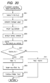
- FIG. 20 is a flowchart which shows the current control timer interruption in accordance with a third embodiment.
- FIG. 1 is a block diagram which shows the embodiment of the present invention.
- a reference numeral designates a five-phase stepping motor (hereinafter referred to as a motor); 1 , a controller that controls the driving of the motor 5 , structured by a microcomputer as an example; 2 , a logic unit for generating driving pulses to drive the motor 5 ; 3 , a pre-driver unit for voltage-converting driving pulses from the logic unit 2 ; 4 , a driver unit for driving the motor 5 by supplying current to each feeding point of the motor 5 in accordance with the driving pulses from the pre-driver unit 3 ; 6 , a current detection resistor (hereinafter referred to as an Rd) to detect the current which flows to the motor 5 ; 7 , a low-pass filter (hereinafter referred to as an LPF) for smoothing the signals obtained by means of the Rd 6 ; and 8 , an A
- Rd current detection resistor
- LPF low-pass filter
- a reference numeral 9 designates an MCLK input terminal for receiving a stepping pulse (hereinafter referred to as MCLK) from the outside to determine a stepping speed of the motor 5 ; 10 , an S/S input terminal for receiving a signal (hereinafter referred to as S/S) which instructs a start/stop of the rotation of the motor 5 ; 11 , a CW/CCW input terminal for receiving a signal (hereinafter referred to CW/CCW) which indicates the rotational direction of the motor 5 ; 12 , a DIV input terminal for receiving a signal (hereinafter referred to as DIV) that indicates the division number of microstep; 13 , a CUR input terminal for receiving a signal (hereinafter referred to as CUR) that indicates the current that flows in the motor 5 ; 14 and 15 , resistors for dividing the power source voltage Vm; 16 , a capacitor for removing noises of a signal divided by the R 1 and R 2 ; and 17 , an AD converter
- FIG. 2 is a block diagram which shows the logic unit 2 .
- a reference numeral 201 designates a counter to be counted up by means of the CLK signal; 202 and 204 , preset registers each for storing data and outputting the data thus stored; 203 and 205 , comparators each for comparing two input data; 206 , an AND gate; and 207 to 211 , pulse generators each for generating a driving pulse.
- FIG. 3 is a block diagram which shows the pulse generator.
- a reference numeral 301 designates a preset register for storing data and outputting the data thus stored;
- 302 a comparator for comparing two input data;
- 303 a dead-time addition circuit;
- 304 an inverter gate;
- 305 an AND gate;
- 306 an OR gate.
- FIG. 4 is a block diagram which shows the dead-time addition circuit 303 .
- a reference numeral 401 designates a delay circuit for delaying a signal by a specific period of time; 402 , an OR gate; and 403 , an AND gate.
- FIG. 5 is a circuit diagram of the pre-driver unit 3 .
- Reference numerals 501 to 520 designate resistors, and 521 to 530 , NPN transistors.
- each of reference marks A+ to E+ is converted to the level of Vm*R 2 /(R 1 +R 2 ) when the transistors 521 to 525 are turned on, and converted to the level of Vm when they are turned off;
- a ⁇ to E ⁇ converted to the level 0 when the transistors 526 to 530 are turned on, and converted to the level of Vm*R 4 /(R 3 +R 4 ) when they are turned off, so as to secure the gate voltage at the FET of the driver unit 4 .
- FIG. 6 is a view which shows the inner circuit of the driver unit 4 and the inner structure of the motor 5 , as well as the wiring thereof.
- reference numeral 601 to 605 designate the PchFET devices; 606 to 610 , the NchFET devices; and 611 to 615 , coils of each phase which correspond to the La to Le, respectively.
- FIGS. 7A to 7 C are time charts for indicating the driving pulses which are generated in accordance with the counting information of the counter 202 shown in FIG. 2, and the status of one feeding point of the motor 5 on the basis thereof.
- FIG. 8 is a time chart for indicating the state of microstep being effectuated by means of driving pulse in terms of the status of each feeding point of the motor 5 .
- FIGS. 9A to 9 E are views which show the current flowing in respective coils of the motor 5 depending on the feeding point status represented in FIG. 8 .
- the motor driving pulses are generated, based on conditions of the CW/CCW, DIV, and CUR, in synchronism with the MCLK, thus the motor 5 being rotated.
- the controller 1 transmits to the logic unit 2 the CLK which becomes clock for the counters or the like in order to generate driving pulses; the STOP that instructs the generation or suspension of driving pulses; and the DATA that transmits the data required for generating pulses.
- the CLK from the controller 1 is inputted into the counter 201 in which it is counted up, and thus counted information is output as the COUNT.
- the count data N form the controller 1 is latched, and the data thus latched are output.
- the comparator 203 the data from the preset register 202 and the COUNT are compared. If these data are in agreement, an identical signal is output.
- This identical signal is inputted into the counter 201 .
- the counter 201 resets the counted value, and begins counting again from 0.
- the counter 201 repeats such an operation as to count up again from 0 to N, like the COUNT shown in FIG. 7A, when the COUNT becomes N from 0 on the basis of the CLK.
- the period of the CLK is constant, the time required for counting up from 0 to N depends on the N. This period is defined as the Tpwm.
- each of the pulse generating devices 207 to 211 generates driving pulses to drive the motor 5 .
- the preset register 202 in the logic unit 2 is assumed to be REGPWM
- the preset register 204 , REGOPEN, and the preset registers 301 in the pulse generating device are assumed to be the REGA, REGB, REGC, REGD, and REGE of the pulse generators 207 to 211 , respectively.
- the pulse generator 207 as an example, the description will be made of the flow of pulse generation as follows.
- the data Na from the controller 1 is latched in the REGA (preset register 301 ), and compared with the aforesaid COUNT in the comparator 302 .
- the dead-time addition circuit 303 produces two signals for determining the status of feeding point so as to drive the motor 5 not to penetrate the PchFET and NchFET of the driver unit 4 simultaneously. These two signals pass the AND gate 305 and OR gate 306 following the signal of the FOPEN in that order to be output as A+ and A ⁇ , and after the level conversion is executed by the predriver 3 , these signals are supplied to the driver unit 4 . Then, the driver unit 4 determines the status of feeding point.
- a delayed signal derived from the delay circuit 401 where an input signal is delayed by a specific time and a non-delayed signal(the input signal) are ANDed and ORed, and are output as the PchFET and NchFET driving pulses, respectively, thus the structure being formed to prevent the penetration of Pch and NchFET owing to the SW characteristics.
- this dead-time is not directly related to the present invention, it is sufficiently smaller than the other pulse period. Hereunder, therefore, the dead-time will be neglected in the description to follow.
- the FOPEN is the signal that enables the status of feeding point to be open.
- the comparator 205 compares such data with the COUNT to output the low level until the COUNT reaches the Nopen and output the high level beyond the Nopen, as shown in FIG. 7 C.
- Such signal enters the AND gate 206 along with the STOP, and an output from the AND gate is transmitted to each of the pulse generators as the FOPEN.
- the STOP becomes low level when the motor 5 rotates.
- the FOPEN is at the high level, all the feeding points are in open status only during the high level period as shown in FIG. 7 C.
- the FOPEN becomes high level, and all the feeding points are in open status so as not to allow current to flow into the motor 5 .
- the motor 5 comes to a stop.
- the driving current flows into the motor 5 , and this period is divided into a microstep period during which the ratio of current to flow into the coil of motor 5 at each phase is determined, and a short period during which the current distributed to each phase is held.
- the motor 5 is thus driven accordingly.
- the PWM period is referenced by a mark Tpwm; the microstep period, by a mark Tms; and the short period, a mark Tsht.
- the feeding point A in the microstep period Tms indicates the push status (+), and the feeding pint D indicates the pull status ( ⁇ ).
- the ratio of the amounts of current flowing in the coils La, Lb, and Lc is determined by the pull/push periods at the feeding points B and C.
- the amounts of current flowing in the Ld and Le are determined by the ratio by the pull/push at the feeding point D.
- all the feeding points are, on the push side, that is, in the status of being turned on to the Vm side by the FET device. Therefore, both ends of each coil are short-circuited to hold current flowing in each coil during this period. Consequently, during the microstep period Tms, the amount of current flowing in each coil is determined, and during the short period Tsht, the current that flows in the entire of the motor is determined.
- FIG. 9E it becomes possible to effectuate one step rotation by means of full step driving.
- the microstep is such that one step by this full step driving is further divided by minutely controlling the ratio of current that flows into each of the coils so as to change the status of each feeding point as shown in FIGS. 8B to 8 D, thus changing the current that flows in each coil as shown in FIGS. 9B to 9 D.
- the motor 5 rotates from the position in FIG. 8A (FIG. 9A) by four angles each formed by dividing one step into four, for each rising of the MCLK, so the motor can be shifted to the four-phase excitation in FIG. 8E (FIG. 9 E). In this manner, it becomes possible to rotate the motor 5 in a desired number of divisions in synchronism with the MCLK by changing the status of each feeding point so as to enable the motor 5 to rotate per MCLK.
- FIG. 10 is a flowchart which shows the main control program stored on the memory of a microcomputer in the controller 1 to control the motor 5 .
- the controller 1 receives the S/S signal that instructs the start of the motor 5 ( 1001 )
- the microstep interruption is admitted ( 1003 )
- the current control timer interruption is admitted as well ( 1004 ).
- the motor 5 is kept in the driving status.
- each of the feeding points is turned into the suspended status, thus executing the suspension process such as the prohibition of each interruption ( 1006 ).
- the status is brought to the motor start standby ( 1001 ).
- FIG. 11 is a flowchart which shows the program of microstep interruption stored on the memory of the microcomputer of the controller 1 , which enables the interruption to be admitted immediately when the MCLK rises.
- the data BUFA to BUFE are set at each of the registers REGA to REGE in each of the pulse generators 207 to 211 ( 1101 ) to generate driving pulses.
- the data that enables the setting of a period larger than the Tpwm is latched in the preset register 204 .
- the FOPEN is kept always in the low level status so as not to allow the open period to be created.
- a period of the MCLK is detected ( 1102 ).
- the instruction by the CW/CCW as to the rotational direction is examined ( 1103 ). If the instructed rotation is the CW, an M (divided position) is incremented ( 1104 ). If the M exceeds the divided number instructed by the DIV ( 1105 ), the M is reset to 0 ( 1006 ) and an N (step number) is incremented ( 1107 ). If the N exceeds 10 ( 1108 ), the N is reset to 0 ( 1109 ).
- the M is decremented ( 1110 ), and when the M is made lower than the divided number ( 1111 ), the divided number ⁇ 1 is set to the M ( 1112 ), and the N is decremented ( 1113 ). If the N is minus ( 1114 ), 9 is set to the N ( 1115 ). Next, the N is set at a P ( 1116 ), and the subroutine DATSET is called to calculate the data needed for setting the excitation pattern at the time of next rising of the MCLK, thus returning it as DATA. Thus, after setting each result of the calculations to the REGA, REGB, REGC, REGD, and REGE, respectively, the process returns from the interruption ( 1117 to 1126 ).
- the Table 1 shows each status of feeding points during the microstep period of 10-step portion (electrical angle 3,600) at the full step.
- the sign + designates the pull status
- the sign ⁇ designates the pull status
- “50%” at the table represents the status where the ratio of the push period the pull period is 1:1.
- the motor 5 indicates the full step driving and rotates in the CW direction.
- each of the feeding points become as follows:
- each status of feeding points at N value can be expressed as follows:
- the DATSET shown in FIG. 11 is a subroutine based thereon to calculate the driving pulses for each of the feeding points.
- FIG. 12 is a flowchart which shows this subroutine program.
- Each of the data BUFA to BUFE on the status of feeding points calculated in FIG. 12 is set at the REGA to REGE, respectively, when the MCLK rises. This process is repeated to switch the excitation patters based on the divided number per MCLK in order to drive the motor 5 , hence making it possible to execute the microstep.
- FIG. 16 is a graph which shows the motor current Im when the width of the open period is changed while keeping the Tpwm, the Tms, and the motor rotational speed constant. As shown in FIG. 16, with the open period being increased, the Im is gradually reduced. This is because when each of the feeding points is in the open status, the counter-electromotive voltage which is generated in the motor causes the motor current to flow reversely through the diode inside the FET device, and the torque is also reduced to that extent. Therefore, it is necessary to make the Tpwm cycle smaller in order to generate the same torque (current).
- FIG. 13 is a flowchart which shows the program of the current control timer interruption.
- the timer interruption is an interruption effectuated per specific period, and the cycle thereof is sufficiently larger than the Tpwm.
- the current setting value which has been set at the current indication CUR is multiplied by Ka ( 1301 ), thus being set as a TPWM, which is compared with Tsd ( 1302 ).
- the Tsd is a period corresponding to the minimum frequency Fsd in the non-audible range.
- the TPWM is the data which is set at the preset register 202 in order to create the Tpwm period. If the TPWM is less than the Tsd, no abnormal sound is generated.
- the TPWM is modified to be a value which is obtained by multiplying the CUR by the Kb ( 1305 ).
- a predetermined open period Top is set as a TDATA ( 1306 ).
- the value obtained by subtracting the TDAT from the TPWM is set at the preset register 204 which determines the Topen period ( 1307 ), thus returning from the interruption.
- the TPWM is smaller than the Tsd, 0 is set at the TDATA ( 1304 ), and the TPWM which has been set in the step 1301 is set as a TOPEN.
- the TPWM being equal to the TOPEN means that the open period is not allowed to be created.
- the status becomes as shown in FIG. 18 if the CUR value is set to make the current Im equal.
- the axis of abscissa indicates the motor speed
- the axis of ordinate indicates the PWM frequency Fpwm.
- FIG. 14 is a view which shows a PI control block that executes the constant-current control with the feedback of the motor current.
- reference numerals 1401 , 1403 , and 1404 designate adders; 1402 , 1405 , and 1407 , multipliers; 1406 , a delay device.
- the constant-current control reads as IDET the data which has been detected by the current detection resistance Rd 6 shown in FIG. 1 and A/D converted in the controller 1 .
- the IDET is compared with a target value TARGET set on the basis of the data from the current indication value CUR, and the result thereof becomes the signal S 1401 .
- the S 1401 is multiplied by the comparative gain Kp using the multiplier 1402 of the comparative controller 1410 . Also, the S 1401 is integrated by use of the adder 1404 of the integral controller 1411 , and, further, multiplied by the integral gain Ki by use of the multiplier 1405 . The respective outputs from the comparative controller 1410 and the integral controller 1411 are added by use of the adder 1403 , and the result thereof is multiplied by the coefficient Ks, which has been selected to be the set current of the current indication CUR, by use of the multiplier 1407 , and set at the preset register 202 as the TPWM. In this manner, the constant-current control is executed.
- FIG. 15 is a flowchart which shows a program of current control timer interruption used when the microstep period Tms of the aforesaid constant-current control is made constant.
- the interruption when the interruption is issued, the data obtained by multiplying the set value of the current indication CUR by a Kt is set at the current target value TARGET ( 1501 ).
- the Kt is a coefficient which has been selected to control speed by the set current CUR.
- the IDET and the TARGET are compared, and the result thereof is set as an ERROR ( 1502 ), and the ERROR is multiplied by the Kp to be set as a PROP ( 1503 ).
- the ERROR is integrated to be set as an INTEG, and then, the value which is obtained by multiplying the INTEG by the Ki, and the PROP are added and the sum is multiplied by the Ks, thus being set at the TPWM ( 1504 , 1505 , and 1506 ). Next, a Tcd is set at the TOPEN ( 1507 ), and the process returns from the interruption.
- FIG. 19 is a graph which shows the Fpwm when the motor speed is changed with an arbitrary current setting value CUR being determined on condition that the Tcd is defined as an adequate value.
- a frequency of the Tcd is given as an Fcd.
- FIG. 17 shows the conventional current control in which on the same condition, no routine in the step 1507 is executed.
- the Fcd is made smaller than the Fpwm as shown in FIG. 19, the inclination indicated in the graph becomes moderate, and the motor speed which is brought into the audible one can be made smaller. Therefore, if only it should be arranged to set the Tcd value so that the lowest speed of the motor 5 does not enter the audible range, the motor 5 can be driven at an adequate current value without generating any abnormal sound.
- it is arranged to execute the current control so that the microstep period is changed until this period becomes the smallest possible microstep Tmsmin in order to execute the control more minutely, and also, to execute the current control by modifying the open period if the microstep period should be made smaller than the Tmsmin.
- FIG. 20 is a flowchart which shows the current control timer interruption when the PWM cycle is made constant for the aforesaid constant current control.
- the data on the set-up current indication CUR multiplied by a Kt is set at the current target value TARGET ( 2001 ).
- the reference mark Kt is a coefficient which has been selected for controlling the speed by the set-up CUR.
- the IDET and the TARGET are compared, and the result thereof is set as an ERROR ( 2002 ).
- the ERROR is multiplied by the Kp to be set as a PROP ( 2003 ).
- the ERROR is integrated to be set as an INTEG which is multiplied by the Ki.
- the value thus obtained and the PROP are added, and multiplied by the Ks, the result of which is set at the TDATA ( 2004 and 2006 ).
- the TDATA thus obtained is compared with the minimum value Tk of the microstep period ( 2007 ). If the TDATA is larger, the TDATA is set at the TMS ( 2011 ). Then, the process returns from the interruption. On the other hand, if the TDATA is smaller, the Tk is set at the TMS ( 2008 ). Then, the Tk is subtracted from the TDATA.
- the value thus obtained is multiplied by a Ko and set as a TBUF ( 2009 ).
- a reference mark Ko is a coefficient which has been selected to make identical the mutual gains between the control with the microstep period being made variable and the control with the open period being made variable.
- the open period is established by setting at the TOPEN the value which is obtained by subtracting the TBUF from the TPWM. Then, the process returns from the interruption. The operation is repeated per interruption to make it possible to perform the constant current control.
- the holding period for holding current in each coil, and the open period during such holding period it becomes possible to drive the motor to rotate with an adequate torque (motor current) by executing the current control which controls such open period even when the microstep period Tms is made the smallest.
Applications Claiming Priority (2)
| Application Number | Priority Date | Filing Date | Title |
|---|---|---|---|
| JP2000187683A JP2002010688A (ja) | 2000-06-22 | 2000-06-22 | モータ駆動制御装置 |
| JP2000-187683 | 2000-06-22 |
Publications (2)
| Publication Number | Publication Date |
|---|---|
| US20020011816A1 US20020011816A1 (en) | 2002-01-31 |
| US6664754B2 true US6664754B2 (en) | 2003-12-16 |
Family
ID=18687622
Family Applications (1)
| Application Number | Title | Priority Date | Filing Date |
|---|---|---|---|
| US09/881,717 Expired - Fee Related US6664754B2 (en) | 2000-06-22 | 2001-06-18 | Motor driving control apparatus |
Country Status (2)
| Country | Link |
|---|---|
| US (1) | US6664754B2 (ja) |
| JP (1) | JP2002010688A (ja) |
Cited By (8)
| Publication number | Priority date | Publication date | Assignee | Title |
|---|---|---|---|---|
| US20030080772A1 (en) * | 2001-08-31 | 2003-05-01 | Davide Giacomini | Programmable compact motor drive module |
| US20080089675A1 (en) * | 2004-10-20 | 2008-04-17 | Narifumi Tojima | Motor-Driving Apparatus |
| US20090026996A1 (en) * | 2007-07-26 | 2009-01-29 | Toshihide Nakane | Pulse motor control device, control method, control program, and imaging apparatus |
| US7716349B1 (en) | 1992-12-09 | 2010-05-11 | Discovery Communications, Inc. | Electronic book library/bookstore system |
| US9030150B2 (en) * | 2009-11-18 | 2015-05-12 | Trinamic Motion Control Gmbh & Co. Kg | Method and circuit arrangement for controlling current in motors |
| US9053640B1 (en) | 1993-12-02 | 2015-06-09 | Adrea, LLC | Interactive electronic book |
| US20180129227A1 (en) * | 2016-11-04 | 2018-05-10 | STMicroelectronics (Grand Ouest) SAS | Method for adaptively driving a stepper motor, and corresponding device |
| US10523148B2 (en) * | 2018-05-08 | 2019-12-31 | Ford Global Technologies, Llc | Reconfigurable winding connection for five-phase permanent magnet electric machine |
Families Citing this family (2)
| Publication number | Priority date | Publication date | Assignee | Title |
|---|---|---|---|---|
| JP2008072876A (ja) * | 2006-09-15 | 2008-03-27 | Asahi Kasei Electronics Co Ltd | ステッピングモータ駆動装置及び駆動方法 |
| DE102009047645A1 (de) * | 2009-12-08 | 2011-06-09 | Robert Bosch Gmbh | Elektromotor mit einem Pulsweitenmodulator |
Citations (5)
| Publication number | Priority date | Publication date | Assignee | Title |
|---|---|---|---|---|
| US5194796A (en) * | 1989-09-04 | 1993-03-16 | Oriental Motor Kabushiki Kaisha | Micro-step drive system of a five-phase stepping motor |
| US5309075A (en) * | 1990-03-23 | 1994-05-03 | Toyoda Koki Kabushiki Kaisha | Digital servo-control apparatus for preventing torque variations |
| US5432424A (en) * | 1992-11-30 | 1995-07-11 | Mita Industrial Co., Ltd. | Motor control device motor control device including a gate element and current controller that controls motor current according to the gate element |
| US6150788A (en) * | 1999-02-16 | 2000-11-21 | Seiberco Incorporated | Load torque detection and drive current optimization determination met |
| US6326748B1 (en) * | 1999-06-09 | 2001-12-04 | Denso Corporation | Brushless motor powered by DC power source |
-
2000
- 2000-06-22 JP JP2000187683A patent/JP2002010688A/ja active Pending
-
2001
- 2001-06-18 US US09/881,717 patent/US6664754B2/en not_active Expired - Fee Related
Patent Citations (5)
| Publication number | Priority date | Publication date | Assignee | Title |
|---|---|---|---|---|
| US5194796A (en) * | 1989-09-04 | 1993-03-16 | Oriental Motor Kabushiki Kaisha | Micro-step drive system of a five-phase stepping motor |
| US5309075A (en) * | 1990-03-23 | 1994-05-03 | Toyoda Koki Kabushiki Kaisha | Digital servo-control apparatus for preventing torque variations |
| US5432424A (en) * | 1992-11-30 | 1995-07-11 | Mita Industrial Co., Ltd. | Motor control device motor control device including a gate element and current controller that controls motor current according to the gate element |
| US6150788A (en) * | 1999-02-16 | 2000-11-21 | Seiberco Incorporated | Load torque detection and drive current optimization determination met |
| US6326748B1 (en) * | 1999-06-09 | 2001-12-04 | Denso Corporation | Brushless motor powered by DC power source |
Cited By (11)
| Publication number | Priority date | Publication date | Assignee | Title |
|---|---|---|---|---|
| US7716349B1 (en) | 1992-12-09 | 2010-05-11 | Discovery Communications, Inc. | Electronic book library/bookstore system |
| US9053640B1 (en) | 1993-12-02 | 2015-06-09 | Adrea, LLC | Interactive electronic book |
| US20030080772A1 (en) * | 2001-08-31 | 2003-05-01 | Davide Giacomini | Programmable compact motor drive module |
| US20080089675A1 (en) * | 2004-10-20 | 2008-04-17 | Narifumi Tojima | Motor-Driving Apparatus |
| US7567046B2 (en) * | 2004-10-20 | 2009-07-28 | Ihi Corporation | Motor-driving apparatus |
| US20090026996A1 (en) * | 2007-07-26 | 2009-01-29 | Toshihide Nakane | Pulse motor control device, control method, control program, and imaging apparatus |
| US7986120B2 (en) * | 2007-07-26 | 2011-07-26 | Sony Corporation | Pulse motor control device, control method, control program, and imaging apparatus |
| US9030150B2 (en) * | 2009-11-18 | 2015-05-12 | Trinamic Motion Control Gmbh & Co. Kg | Method and circuit arrangement for controlling current in motors |
| US20180129227A1 (en) * | 2016-11-04 | 2018-05-10 | STMicroelectronics (Grand Ouest) SAS | Method for adaptively driving a stepper motor, and corresponding device |
| US10248135B2 (en) * | 2016-11-04 | 2019-04-02 | STMicroelectronics (Grand Ouest) SAS | Method for adaptively driving a stepper motor, and corresponding device |
| US10523148B2 (en) * | 2018-05-08 | 2019-12-31 | Ford Global Technologies, Llc | Reconfigurable winding connection for five-phase permanent magnet electric machine |
Also Published As
| Publication number | Publication date |
|---|---|
| JP2002010688A (ja) | 2002-01-11 |
| US20020011816A1 (en) | 2002-01-31 |
Similar Documents
| Publication | Publication Date | Title |
|---|---|---|
| US5463299A (en) | Current controller for controlling a current flowing in a load using a PWM inverter and method used thereby | |
| US6545443B2 (en) | Pulse width modulation circuit controlling output current of an inverter circuit for motor-driven blower or electric vacuum cleaner | |
| US7518328B2 (en) | Method and device for commutating electromechanical actuators | |
| US7141945B2 (en) | Method and apparatus for controlling motor drive | |
| US6664754B2 (en) | Motor driving control apparatus | |
| US6366048B2 (en) | Method and arrangement for regulating the current in a switched reluctance machine | |
| US6700342B2 (en) | Method and apparatus for high performance permanent magnet motor speed control with limited position information | |
| KR100822990B1 (ko) | 브러시리스 dc 모터 제어 | |
| JP4050489B2 (ja) | モータの制御方法 | |
| US6359413B1 (en) | Current control system for a switched reluctance motor | |
| JP6769246B2 (ja) | 電動機制御装置 | |
| JP2000184789A (ja) | ステッピングモ―タの駆動方法 | |
| JP2007028839A (ja) | 三相ステッピングモータの駆動回路 | |
| JP3815238B2 (ja) | モータの回転制御方法 | |
| JP2767827B2 (ja) | 可変リラクタンスモータの回転制御装置 | |
| JPH04229099A (ja) | ステッピングモータのための制御装置 | |
| JP2000116173A (ja) | ブラシレス直流電動機及びその速度制御方法 | |
| JP3428243B2 (ja) | 電動機の速度制御装置 | |
| US6407527B1 (en) | Motor drive control apparatus | |
| JP2022010912A (ja) | モータ駆動制御装置およびファンユニット | |
| JP2002010687A (ja) | モータ駆動制御装置 | |
| JP3785313B2 (ja) | ステッピングモータ装置、ステッピングモータ用制御装置及び、ステッピングモータ | |
| JP2003033087A (ja) | モータ駆動制御装置 | |
| JPS5930639Y2 (ja) | パルスモ−タ駆動回路 | |
| JP5239273B2 (ja) | モータ駆動制御装置 |
Legal Events
| Date | Code | Title | Description |
|---|---|---|---|
| AS | Assignment |
Owner name: CANON KABUSHIKI KAISHA, JAPAN Free format text: ASSIGNMENT OF ASSIGNORS INTEREST;ASSIGNOR:MISUMI, HIROYOSHI;REEL/FRAME:011916/0356 Effective date: 20010612 |
|
| CC | Certificate of correction | ||
| FEPP | Fee payment procedure |
Free format text: PAYOR NUMBER ASSIGNED (ORIGINAL EVENT CODE: ASPN); ENTITY STATUS OF PATENT OWNER: LARGE ENTITY |
|
| FPAY | Fee payment |
Year of fee payment: 4 |
|
| REMI | Maintenance fee reminder mailed | ||
| LAPS | Lapse for failure to pay maintenance fees | ||
| STCH | Information on status: patent discontinuation |
Free format text: PATENT EXPIRED DUE TO NONPAYMENT OF MAINTENANCE FEES UNDER 37 CFR 1.362 |
|
| FP | Lapsed due to failure to pay maintenance fee |
Effective date: 20111216 |