US6402896B1 - Roll for a paper or board machine - Google Patents
Roll for a paper or board machine Download PDFInfo
- Publication number
- US6402896B1 US6402896B1 US09/581,279 US58127900A US6402896B1 US 6402896 B1 US6402896 B1 US 6402896B1 US 58127900 A US58127900 A US 58127900A US 6402896 B1 US6402896 B1 US 6402896B1
- Authority
- US
- United States
- Prior art keywords
- roll
- mantle
- bores
- blind
- holes
- Prior art date
- Legal status (The legal status is an assumption and is not a legal conclusion. Google has not performed a legal analysis and makes no representation as to the accuracy of the status listed.)
- Expired - Lifetime
Links
Images


Classifications
-
- F—MECHANICAL ENGINEERING; LIGHTING; HEATING; WEAPONS; BLASTING
- F26—DRYING
- F26B—DRYING SOLID MATERIALS OR OBJECTS BY REMOVING LIQUID THEREFROM
- F26B13/00—Machines and apparatus for drying fabrics, fibres, yarns, or other materials in long lengths, with progressive movement
- F26B13/10—Arrangements for feeding, heating or supporting materials; Controlling movement, tension or position of materials
- F26B13/14—Rollers, drums, cylinders; Arrangement of drives, supports, bearings, cleaning
- F26B13/16—Rollers, drums, cylinders; Arrangement of drives, supports, bearings, cleaning perforated in combination with hot air blowing or suction devices, e.g. sieve drum dryers
-
- D—TEXTILES; PAPER
- D21—PAPER-MAKING; PRODUCTION OF CELLULOSE
- D21F—PAPER-MAKING MACHINES; METHODS OF PRODUCING PAPER THEREON
- D21F3/00—Press section of machines for making continuous webs of paper
- D21F3/02—Wet presses
- D21F3/10—Suction rolls, e.g. couch rolls
Definitions
- the present invention relates to a roll for a paper or board machine, and in particular to a roll of the type having a number or openings extending through the mantle.
- a web forming section employs mainly suction rolls which usually comprise a perforated roll mantle attached to end flanges at the ends of the roll.
- the end flanges are in turn journalled rotatably on attachment flanges situated at the ends of the roll and attached to the frame of the machine.
- Inside the roll mantle. there may be a static suction box attached to the attachment flanges enabling suction to be applied to a given sector of the suction roll.
- the interior of the roll may also be empty, in which case suction is applied to the entire circumference of the roll mantle.
- the ends of the roll are provided with ducts by which an external source of negative pressure can be connected to the roll.
- bores extending through the roll mantle are normally provided. in the outer surface of the mantle, with countersinks by means of which the unbroken connecting portions surrounding the holes of the bores in the outer surface of the roll mantle are made smaller and the open area of the outer surface of the roll mantle is increased.
- the press section of paper or board machines in turn employs rolls which have a roll mantle that is perforated or provided with blind-drilled bores.
- the interior of the roll is not necessarily connected to a separate source of negative pressure.
- water is sucked into the holes, blind-drilled bores or other recesses of the roll mantle and removed from them after the press nip by means of the centrifugal force.
- the mantle of press section rolls is normally coated with a material that is softer than steel, for example, with some rubber-like material.
- blind-drilled bores in a roll provided with a coated mantle may extend some distance into the steel mantle or merely into the coating depending on a desired volume of the bores.
- both through bores and blind-drilled bores are normally provided with countersinks in the outer surface of the mantle for reducing the size of the unbroken connecting portions that surround the holes or recesses in the outer surface of the roll mantle and for enlarging the open area of the outer surface of the roll mantle.
- DE patent 21 40 776 discloses a suction roll of a paper machine comprising a mantle stiffened against bending and a perforation extending through the mantle of the roll and forming a certain pattern. Additionally, the mantle surface of the roll is provided with grooves that connect a row of holes so that a symmetrical embossed pattern of the surface is formed in practice. The hole area in the surface of the roll mantle is over 50% and it may be nearly 90% of the total area of the roll mantle. It is also stated in the publication that some of the above-mentioned holes may be blind-drilled bores or that, in addition to the above-mentioned holes, blind-drilled bores are made into the surface of the mantle for improving the water retention capacity of the roll. In this arrangement, the connecting surface of the walls between two adjacent grooves in the surface of the mantle forms a solid connecting portion supporting the wire or equivalent.
- the roll in accordance with the invention provides a very good and even flow of water into the holes extending through the mantle of the roll and/or into the blind-drilled bores and/or equivalent openings situated in the outer surface of the roll mantle. Moreover, in the roll in accordance with the invention, no separate wire sock is needed on the outer surface of the roll mantle.
- the open area of the outer surface of the mantle of the roll in accordance with the invention is about 70-90% depending on the application.
- the arrangement of the invention may be used in a roll of a paper or board machine which comprises either openings extending through the roll mantle, e.g. through bores, or recesses formed into the outer surface of the mantle, e.g. blind-drilled bores, or a combination of them.
- Such rolls are used, for example, in a web former and in a press section.
- the invention may be used in a suction roll where suction is applied to the circumference of the entire mantle or in a suction roll having a static suction box by means of which suction is applied to a given sector of the roll.
- the arrangement in accordance with the invention may also be used in a roll which employs no external source of negative pressure, by which a negative pressure is maintained in the interior of the roll.
- a negative pressure is maintained in the interior of the roll.
- the water that is being removed from the web is transferred into the holes and/or blind-drilled bores of the roll mantle at the point of compression by the action of a pressure difference produced in the wire or equivalent supporting the web.
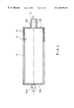
- FIG. 1 is a schematic sectional view of a suction roll.
- FIG. 2 shows one embodiment of a surface pattern in a mantle of a roll in accordance with the invention.
- FIG. 3 shows a variant of the embodiment of FIG. 2 .
- FIG. 4 shows a second embodiment of a surface pattern in a mantle of a roll in accordance with the invention.
- FIG. 5 shows a third embodiment of a surface pattern in a mantle of a roll in accordance with the invention.
- FIG. 1 is a view of principle of a suction roll where the arrangement in accordance with the invention may be used.
- the suction roll comprises a roll mantle 11 , which is rotatably journalled on axle journals 13 A and 13 B connected to the roll mantle 11 through end flanges 12 A and 12 B.
- the roll mantle 11 has perforations 15 which are formed of numerous holes 15 extending through the roll mantle 11 .
- the figure shows only some of the perforations 15 of the mantle 11 .
- the interior of the roll is here empty, but inside the roll there may also be a suction box by means of which suction is guided to a given sector of the roll mantle.
- At least one 13 B of the axle journals comprises ducts which lead to the interior of the roll and to which an external source of negative pressure (not shown in the figure) can be connected. Air is sucked out (arrow P 2 ) by means of the source of negative pressure from the entire interior of the roll or at the sector formed by the suction box, in which connection a corresponding amount of air (arrow P 1 ) flows into the roll through the perforations 15 of the roll mantle.
- the perforations 15 of the roll mantle 11 may be composed of bores extending with the same diameter through the entire mantle 11 or countersinks may have been made into the bores in the outer surface of the mantle 11 . whereby the area of the holes 15 opening into the outer surface of the mantle 11 has been enlarged.
- the perforations 15 of the roll mantle 11 are advantageously formed to be spiral-shaped so that the holes are not situated in rows in the axial direction of the roll.
- the diameter of the holes 15 is generally about 2-5 mm and the diameter of the countersinks is generally about 2-15 mm.
- FIG. 2A shows one embodiment of a pattern in an outer surface of a mantle of a roll in accordance with the invention.
- the holes and/or blind-drilled bores or their countersinks 15 situated in the roll mantle form a regular pattern in the outer surface of the roll mantle.
- Through a line formed by the centres of the holes and/or blind-drilled bores 15 it is possible to draw a curve which extends spirally along the outer surface of the roll mantle and whose angle of spiral relative to the axis X—X of the roll is ⁇ .
- said angle ⁇ is about 45°, but in practical applications the angle of spiral ⁇ is, however, considerably smaller than 45° in order that the holes and/or blind-drilled bores 15 shall not be placed in rows parallel to the axis X—X of the roll.
- the angle of spiral ⁇ is about 10°.
- the arrangement in accordance with the invention may in itself be used at any angle of spiral ⁇ and with any regular pattern formed by holes and/or blind-drilled bores.
- the row formed by the holes and/or blind-drilled bores 15 in a first direction S 1 in FIG. 2A is connected by means of a first groove 16 formed into the outer surface of the roll mantle and the row formed by these holes and/or blind-drilled bores 15 in a second direction S 2 is connected by means of a second groove 17 formed into the outer surface of the roll mantle.
- This figure depicts only two adjacent grooves 16 running in the first direction S 1 and two adjacent grooves 17 running in the second direction S 2 .
- the width of the crossing grooves 16 , 17 in the outer surface of the roll mantle corresponds substantially to the diameter of the holes and/or blind-drilled bores or their countersinks 15 in the outer surface of mantle.
- a solid connecting portion 16 ′ is formed between the adjacent grooves 16 in the outer surface of the mantle, which connecting portion prevents a free flow of water into the holes and/or blind-drilled bores 15 .
- This solid connecting portion 16 ′ is broken by means of the second grooving 17 situated crosswise with respect to the first grooving 16 and formed on the holes and/or blind-drilled bores 15 .
- the open area of the outer surface of the roll mantle can be enlarged at its maximum by about 90% so that only the small square-shaped support points 18 support the wire running on the surface of the roll. From the edges of the square-shaped support points 18 , the surface of the mantle inclines into the mantle and opens into the holes and/or blind-drilled bores 15 of the mantle, in which connection the water removed from the web is able to flow freely and evenly into the holes and/or openings of the mantle.
- FIG. 2B shows a cross section of the roll mantle at the support points 18 .
- the cross section shows a profile of the grooves 16 , 17 which is advantageously in the shape of a cone widening upwards to the outer surface of the mantle.
- the support points 18 are depicted here such that their outer surface constitutes a plane, which is the most preferable arrangement from the point of view of the manufacturing technique.
- the outer surface of the support points is hemispherical so that the edges of the square-shaped support points will not form a sharp angulation for the wire.
- the hemispherical surface provides a smooth support surface for the wire moving on the surface of the roll.
- the depth of the grooves 16 , 17 is advantageously about 1.5-2 mm and they may be made into the outer surface of the roll mantle, for example, by turning, milling or knurling.
- FIG. 3 shows a variant of the embodiment of FIG. 2 .
- grooves 40 , 41 formed in first S 1 and second S 2 directions are provided between rows of holes and/or blind-drilled bores 15 such that the edges of the grooves 40 , 41 form a tangent to the holes and/blind-drilled bores or their countersinks 15 in the outer surface of the mantle.
- four support points 42 for a wire or an equivalent member supporting the web around each hole and/or blind-drilled bore or their countersink 15 , there remain, in the outer surface of the mantle, four support points 42 for a wire or an equivalent member supporting the web.
- the open area of the outer surface of the mantle provided by this embodiment is not as large as that of the embodiment illustrated in FIG. 2, but in this case, too, water moves relatively efficiently and evenly into the holes and/or blind-drilled bores 15 .
- FIG. 4 shows a second embodiment of a pattern in an outer surface of a roll mantle in accordance with the invention.
- the holes and/or blind-drilled bores or their countersinks 15 situated in the roll mantle are shown in the figure as completely filled circles.
- circular grooves 30 are formed into the outer surface of the roll mantle. The grooves 30 are made such that the centre of each groove 30 coincides with the centre of the holes and/or blind-drilled bores 15 and the centre radius of the grooves 30 is equal to the distance between the centres of the holes and/or blind-drilled bores 15 .
- the centres of the holes and/or blind-drilled bores 15 are situated in this example at the apices of an equilateral triangle.
- the outer surface of the mantle surrounding the holes and/or blind-drilled bores or their countersinks 15 can be opened by means of said grooves 30 .
- Connecting channels extending to the depth of the grooves 30 are thus formed between the holes and/or blind-drilled bores or their countersinks 15 in the outer surface of the mantle.
- the wire or equivalent is supported by triangular support points 31 .
- the open area of the outer surface of the roll mantle can be regulated in this embodiment by regulating the width of the grooves 30 . This embodiment, too. provides an efficient flow of water into the holes and/or blind-drilled bores 15 .
- FIG. 5 shows a third embodiment of a pattern in an outer surface of a mantle of a roll in accordance with the invention.
- blind-drilled bores 50 are provided between holes and/or blind-drilled bores or their countersinks 15 such that each blind-drilled bore opens a connection to the closest holes and/or blind-drilled bores or their countersinks 15 surrounding it.
- the open area of the roll mantle can be enlarged.
- the size of the open area of the outer surface of the mantle depends in this embodiment, among other things, on what kind of pattern the holes and/or blind-drilled bores 15 form in the outer surface of the mantle. If blind-drilled bores 50 are made to the hole pattern shown in FIG. 4, a relatively large open area can be achieved, and if blind-drilled bores 50 are made to the hole pattern shown in FIG. 5, a slightly smaller open area is achieved.
- the support points supporting the wire are here denoted with the reference numeral 51 .
Landscapes
- Engineering & Computer Science (AREA)
- Textile Engineering (AREA)
- Mechanical Engineering (AREA)
- General Engineering & Computer Science (AREA)
- Paper (AREA)
- Machines For Manufacturing Corrugated Board In Mechanical Paper-Making Processes (AREA)
- Replacement Of Web Rolls (AREA)
- Electron Beam Exposure (AREA)
- Preparing Plates And Mask In Photomechanical Process (AREA)
Priority Applications (1)
| Application Number | Priority Date | Filing Date | Title |
|---|---|---|---|
| US10/166,159 US6682632B2 (en) | 1997-12-10 | 2002-06-10 | Roll for a paper or board machine |
Applications Claiming Priority (3)
| Application Number | Priority Date | Filing Date | Title |
|---|---|---|---|
| FI974480 | 1997-12-10 | ||
| FI974480A FI111861B (fi) | 1997-12-10 | 1997-12-10 | Paperi- tai kartonkikoneen tela |
| PCT/FI1998/000943 WO1999032713A1 (en) | 1997-12-10 | 1998-12-03 | Roll for a paper or board machine |
Related Parent Applications (1)
| Application Number | Title | Priority Date | Filing Date |
|---|---|---|---|
| PCT/FI1998/000943 A-371-Of-International WO1999032713A1 (en) | 1997-12-10 | 1998-12-03 | Roll for a paper or board machine |
Related Child Applications (1)
| Application Number | Title | Priority Date | Filing Date |
|---|---|---|---|
| US10/166,159 Continuation US6682632B2 (en) | 1997-12-10 | 2002-06-10 | Roll for a paper or board machine |
Publications (1)
| Publication Number | Publication Date |
|---|---|
| US6402896B1 true US6402896B1 (en) | 2002-06-11 |
Family
ID=8550100
Family Applications (2)
| Application Number | Title | Priority Date | Filing Date |
|---|---|---|---|
| US09/581,279 Expired - Lifetime US6402896B1 (en) | 1997-12-10 | 1998-12-03 | Roll for a paper or board machine |
| US10/166,159 Expired - Fee Related US6682632B2 (en) | 1997-12-10 | 2002-06-10 | Roll for a paper or board machine |
Family Applications After (1)
| Application Number | Title | Priority Date | Filing Date |
|---|---|---|---|
| US10/166,159 Expired - Fee Related US6682632B2 (en) | 1997-12-10 | 2002-06-10 | Roll for a paper or board machine |
Country Status (12)
| Country | Link |
|---|---|
| US (2) | US6402896B1 (fi) |
| EP (1) | EP1060308B1 (fi) |
| JP (1) | JP3670961B2 (fi) |
| KR (1) | KR100433151B1 (fi) |
| CN (1) | CN1095903C (fi) |
| AT (1) | ATE272147T1 (fi) |
| AU (1) | AU1437499A (fi) |
| BR (1) | BR9815168B1 (fi) |
| CA (1) | CA2312781C (fi) |
| DE (1) | DE69825321T2 (fi) |
| FI (1) | FI111861B (fi) |
| WO (1) | WO1999032713A1 (fi) |
Cited By (3)
| Publication number | Priority date | Publication date | Assignee | Title |
|---|---|---|---|---|
| EP1375743A1 (de) * | 2002-06-21 | 2004-01-02 | Voith Paper Patent GmbH | Walze für eine Papiermaschine und Verfahren zu ihrer Herstellung |
| US20070029061A1 (en) * | 2005-08-05 | 2007-02-08 | Thomas Scherb | Machine for the production of tissue paper |
| US20130213879A1 (en) * | 2010-10-27 | 2013-08-22 | Andritz Ag | Suction roll for dewatering a fibrous web |
Families Citing this family (14)
| Publication number | Priority date | Publication date | Assignee | Title |
|---|---|---|---|---|
| GB9924646D0 (en) * | 1999-10-19 | 1999-12-22 | Voith Fabrics Blackburn Ltd | Improvements in roll covers |
| DE10227842A1 (de) * | 2002-06-21 | 2004-01-08 | Voith Paper Patent Gmbh | Walze zur Entwässerung einer Faserstoffbahn, Verfahren zur Herstellung einer solchen Walze und deren Verwendung |
| DE10327248A1 (de) * | 2003-06-17 | 2005-01-05 | Voith Paper Patent Gmbh | Walze, insbesondere Formierwalze |
| DE10327246A1 (de) * | 2003-06-17 | 2005-01-05 | Voith Paper Patent Gmbh | Walze, insbesondere Formierwalze |
| DE10327244A1 (de) * | 2003-06-17 | 2005-01-05 | Voith Paper Patent Gmbh | Walze, insbesondere Formierwalze |
| DE10341237A1 (de) * | 2003-09-08 | 2005-03-24 | Voith Paper Patent Gmbh | Walze zur Herstellung und/oder Behandlung einer Faserstoffbahn und Verfahren zur Herstellung der Walze |
| FI116076B (fi) | 2004-02-10 | 2005-09-15 | Metso Paper Inc | Uritettu rainanmuodostustela |
| DE102004032858A1 (de) * | 2004-07-07 | 2006-02-16 | Voith Paper Patent Gmbh | Doppelsiebformer in einer Maschine zur Herstellung einer Faserstoffbahn und Verfahren zum Herstellen einer Faserstoffbahn |
| DE102004050263A1 (de) | 2004-10-14 | 2006-04-27 | Voith Paper Patent Gmbh | Walze zur Herstellung und/oder Behandlung einer Faserstoffbahn, Verfahren zur Herstellung der Walze und Anwendung der Walze |
| DE102009028215B3 (de) * | 2009-08-04 | 2010-09-09 | Voith Patent Gmbh | Kombination eines Pressfilzes mit einem Presswalzenbezug und/oder einem Saugwalzenbezug für eine Papiermaschine |
| CN102373643A (zh) * | 2010-08-09 | 2012-03-14 | 河南省江河纸业有限责任公司 | 一种真空压榨辊 |
| SE535820C2 (sv) | 2010-10-05 | 2013-01-02 | Stora Enso Oyj | Process för torkning av massa med hjälp av en perforerad sugvals |
| DE102011077638A1 (de) * | 2011-06-16 | 2012-12-20 | Mwn In Niefern Maschinenfabrik Gmbh | Walze und Herstellungsverfahren für eine Walze |
| MX2018009154A (es) * | 2016-04-26 | 2018-11-09 | Stowe Woodward Licensco Llc | Rodillo de succion con patron de orificios pasantes y orificios ciegos perforados que mejora la distancia de tierra. |
Citations (5)
| Publication number | Priority date | Publication date | Assignee | Title |
|---|---|---|---|---|
| US1805780A (en) * | 1926-12-13 | 1931-05-19 | Paper & Textile Machinery Comp | Countersunk suction roll shell |
| DE2140776A1 (de) | 1970-08-20 | 1972-02-24 | Dominion Engineering Works, Ltd., Toronto, Ontario (Kanada) | Saugwalze |
| US4366025A (en) * | 1981-06-04 | 1982-12-28 | Beloit Corporation | Suction press roll |
| DE3210320A1 (de) | 1982-03-20 | 1983-09-29 | J.M. Voith Gmbh, 7920 Heidenheim | Saugwalze, insbesondere fuer doppelsieb-papiermaschinen |
| US5135614A (en) * | 1989-12-12 | 1992-08-04 | Valmet Paper Machinery Inc. | Suction roll for a paper making machine and a method for producing a desired pressure profile for the suction roll |
-
1997
- 1997-12-10 FI FI974480A patent/FI111861B/fi not_active IP Right Cessation
-
1998
- 1998-12-03 JP JP2000525624A patent/JP3670961B2/ja not_active Expired - Fee Related
- 1998-12-03 DE DE69825321T patent/DE69825321T2/de not_active Expired - Lifetime
- 1998-12-03 AU AU14374/99A patent/AU1437499A/en not_active Abandoned
- 1998-12-03 WO PCT/FI1998/000943 patent/WO1999032713A1/en active IP Right Grant
- 1998-12-03 US US09/581,279 patent/US6402896B1/en not_active Expired - Lifetime
- 1998-12-03 CN CN98812052A patent/CN1095903C/zh not_active Expired - Fee Related
- 1998-12-03 CA CA002312781A patent/CA2312781C/en not_active Expired - Fee Related
- 1998-12-03 AT AT98958272T patent/ATE272147T1/de active
- 1998-12-03 KR KR10-2000-7006103A patent/KR100433151B1/ko not_active IP Right Cessation
- 1998-12-03 EP EP98958272A patent/EP1060308B1/en not_active Expired - Lifetime
- 1998-12-03 BR BRPI9815168-1A patent/BR9815168B1/pt not_active IP Right Cessation
-
2002
- 2002-06-10 US US10/166,159 patent/US6682632B2/en not_active Expired - Fee Related
Patent Citations (5)
| Publication number | Priority date | Publication date | Assignee | Title |
|---|---|---|---|---|
| US1805780A (en) * | 1926-12-13 | 1931-05-19 | Paper & Textile Machinery Comp | Countersunk suction roll shell |
| DE2140776A1 (de) | 1970-08-20 | 1972-02-24 | Dominion Engineering Works, Ltd., Toronto, Ontario (Kanada) | Saugwalze |
| US4366025A (en) * | 1981-06-04 | 1982-12-28 | Beloit Corporation | Suction press roll |
| DE3210320A1 (de) | 1982-03-20 | 1983-09-29 | J.M. Voith Gmbh, 7920 Heidenheim | Saugwalze, insbesondere fuer doppelsieb-papiermaschinen |
| US5135614A (en) * | 1989-12-12 | 1992-08-04 | Valmet Paper Machinery Inc. | Suction roll for a paper making machine and a method for producing a desired pressure profile for the suction roll |
Cited By (5)
| Publication number | Priority date | Publication date | Assignee | Title |
|---|---|---|---|---|
| EP1375743A1 (de) * | 2002-06-21 | 2004-01-02 | Voith Paper Patent GmbH | Walze für eine Papiermaschine und Verfahren zu ihrer Herstellung |
| US20070029061A1 (en) * | 2005-08-05 | 2007-02-08 | Thomas Scherb | Machine for the production of tissue paper |
| US8303773B2 (en) | 2005-08-05 | 2012-11-06 | Voith Patent Gmbh | Machine for the production of tissue paper |
| US20130213879A1 (en) * | 2010-10-27 | 2013-08-22 | Andritz Ag | Suction roll for dewatering a fibrous web |
| US8778142B2 (en) * | 2010-10-27 | 2014-07-15 | Andritz Ag | Suction roll for dewatering a fibrous web |
Also Published As
| Publication number | Publication date |
|---|---|
| AU1437499A (en) | 1999-07-12 |
| FI974480A (fi) | 1999-06-11 |
| FI974480A0 (fi) | 1997-12-10 |
| WO1999032713A1 (en) | 1999-07-01 |
| BR9815168B1 (pt) | 2008-11-18 |
| US6682632B2 (en) | 2004-01-27 |
| US20030008757A1 (en) | 2003-01-09 |
| ATE272147T1 (de) | 2004-08-15 |
| DE69825321D1 (de) | 2004-09-02 |
| BR9815168A (pt) | 2000-10-10 |
| DE69825321T2 (de) | 2005-08-04 |
| JP3670961B2 (ja) | 2005-07-13 |
| KR100433151B1 (ko) | 2004-05-27 |
| FI111861B (fi) | 2003-09-30 |
| JP2001527169A (ja) | 2001-12-25 |
| CA2312781C (en) | 2008-11-25 |
| KR20010032792A (ko) | 2001-04-25 |
| CN1281519A (zh) | 2001-01-24 |
| CN1095903C (zh) | 2002-12-11 |
| EP1060308B1 (en) | 2004-07-28 |
| EP1060308A1 (en) | 2000-12-20 |
| CA2312781A1 (en) | 1999-07-01 |
Similar Documents
| Publication | Publication Date | Title |
|---|---|---|
| US6402896B1 (en) | Roll for a paper or board machine | |
| USRE37657E1 (en) | Support or pressure roll for a paper roll winder | |
| CA2031691C (en) | Suction roll for a paper making machine and a method for producing a desired pressure profile for the suction roll | |
| KR900002104B1 (ko) | 긴 닙프레스용 베어링 블랭킷 | |
| JP2782477B2 (ja) | スラリー処理用プレス | |
| US6029570A (en) | Press jacket for a press device | |
| US5024729A (en) | Suction roll with turbulence suppression element | |
| EP1103654B1 (en) | Roll | |
| FI116076B (fi) | Uritettu rainanmuodostustela | |
| US6986831B2 (en) | Suction roll of a paper machine | |
| KR102441853B1 (ko) | 헤링본 패턴을 가지는 저널 포일 공기 베어링 | |
| CN112189123B (zh) | 纤维幅材机的带沟纹和穿孔的转向辊 | |
| FI80917B (fi) | Anordning foer silning av fibersuspension. | |
| EP1321569A1 (de) | Saugwalze | |
| US20030066618A1 (en) | Machine for the production of a fiber web |
Legal Events
| Date | Code | Title | Description |
|---|---|---|---|
| AS | Assignment |
Owner name: VALMET CORPORATION, FINLAND Free format text: ASSIGNMENT OF ASSIGNORS INTEREST;ASSIGNORS:NIKULAINEN, OSMO;KARTTUNEN, HEIKKI;LEINONEN, ANTTI;AND OTHERS;REEL/FRAME:010991/0013;SIGNING DATES FROM 20000426 TO 20000515 |
|
| AS | Assignment |
Owner name: METSO PAPER, INC., FINLAND Free format text: CHANGE OF NAME;ASSIGNOR:VALMET CORPORATION;REEL/FRAME:012466/0973 Effective date: 20010101 |
|
| STCF | Information on status: patent grant |
Free format text: PATENTED CASE |
|
| FEPP | Fee payment procedure |
Free format text: PAYER NUMBER DE-ASSIGNED (ORIGINAL EVENT CODE: RMPN); ENTITY STATUS OF PATENT OWNER: LARGE ENTITY Free format text: PAYOR NUMBER ASSIGNED (ORIGINAL EVENT CODE: ASPN); ENTITY STATUS OF PATENT OWNER: LARGE ENTITY |
|
| FPAY | Fee payment |
Year of fee payment: 4 |
|
| CC | Certificate of correction | ||
| FPAY | Fee payment |
Year of fee payment: 8 |
|
| FPAY | Fee payment |
Year of fee payment: 12 |
|
| AS | Assignment |
Owner name: VALMET TECHNOLOGIES, INC., FINLAND Free format text: CHANGE OF NAME;ASSIGNOR:METSO PAPER, INC.;REEL/FRAME:032551/0426 Effective date: 20131212 |