US6158329A - Cooking appliance with temperature sensor - Google Patents
Cooking appliance with temperature sensor Download PDFInfo
- Publication number
- US6158329A US6158329A US09/516,657 US51665700A US6158329A US 6158329 A US6158329 A US 6158329A US 51665700 A US51665700 A US 51665700A US 6158329 A US6158329 A US 6158329A
- Authority
- US
- United States
- Prior art keywords
- mouth
- feeding device
- cooling
- cooking
- air
- Prior art date
- Legal status (The legal status is an assumption and is not a legal conclusion. Google has not performed a legal analysis and makes no representation as to the accuracy of the status listed.)
- Expired - Fee Related
Links
- 238000010411 cooking Methods 0.000 title claims abstract description 109
- 238000000605 extraction Methods 0.000 claims abstract description 33
- 238000005259 measurement Methods 0.000 claims abstract description 16
- 230000005855 radiation Effects 0.000 claims abstract description 5
- XLYOFNOQVPJJNP-UHFFFAOYSA-N water Chemical compound O XLYOFNOQVPJJNP-UHFFFAOYSA-N 0.000 claims description 10
- 230000006735 deficit Effects 0.000 abstract description 2
- 238000001816 cooling Methods 0.000 description 14
- 230000000694 effects Effects 0.000 description 4
- 238000000034 method Methods 0.000 description 4
- 238000009529 body temperature measurement Methods 0.000 description 2
- 238000011156 evaluation Methods 0.000 description 2
- 238000010438 heat treatment Methods 0.000 description 2
- 238000013021 overheating Methods 0.000 description 2
- 230000001681 protective effect Effects 0.000 description 2
- 238000010276 construction Methods 0.000 description 1
- 230000007257 malfunction Effects 0.000 description 1
- 238000012986 modification Methods 0.000 description 1
- 230000004048 modification Effects 0.000 description 1
- 238000012544 monitoring process Methods 0.000 description 1
- 239000002245 particle Substances 0.000 description 1
- 230000035515 penetration Effects 0.000 description 1
- 230000032258 transport Effects 0.000 description 1
Images
Classifications
-
- F—MECHANICAL ENGINEERING; LIGHTING; HEATING; WEAPONS; BLASTING
- F24—HEATING; RANGES; VENTILATING
- F24C—DOMESTIC STOVES OR RANGES ; DETAILS OF DOMESTIC STOVES OR RANGES, OF GENERAL APPLICATION
- F24C15/00—Details
- F24C15/20—Removing cooking fumes
- F24C15/2007—Removing cooking fumes from oven cavities
-
- F—MECHANICAL ENGINEERING; LIGHTING; HEATING; WEAPONS; BLASTING
- F24—HEATING; RANGES; VENTILATING
- F24C—DOMESTIC STOVES OR RANGES ; DETAILS OF DOMESTIC STOVES OR RANGES, OF GENERAL APPLICATION
- F24C15/00—Details
- F24C15/006—Arrangements for circulation of cooling air
-
- F—MECHANICAL ENGINEERING; LIGHTING; HEATING; WEAPONS; BLASTING
- F24—HEATING; RANGES; VENTILATING
- F24C—DOMESTIC STOVES OR RANGES ; DETAILS OF DOMESTIC STOVES OR RANGES, OF GENERAL APPLICATION
- F24C7/00—Stoves or ranges heated by electric energy
- F24C7/08—Arrangement or mounting of control or safety devices
-
- Y—GENERAL TAGGING OF NEW TECHNOLOGICAL DEVELOPMENTS; GENERAL TAGGING OF CROSS-SECTIONAL TECHNOLOGIES SPANNING OVER SEVERAL SECTIONS OF THE IPC; TECHNICAL SUBJECTS COVERED BY FORMER USPC CROSS-REFERENCE ART COLLECTIONS [XRACs] AND DIGESTS
- Y10—TECHNICAL SUBJECTS COVERED BY FORMER USPC
- Y10S—TECHNICAL SUBJECTS COVERED BY FORMER USPC CROSS-REFERENCE ART COLLECTIONS [XRACs] AND DIGESTS
- Y10S99/00—Foods and beverages: apparatus
- Y10S99/14—Induction heating
Definitions
- the present invention concerns a cooking appliance having a cooking space for receiving a product to be cooked.
- a cooling-air feeding device and a sensor module are provided for sensing an infrared radiation of a surface area of the product to be cooked or the interior of the cooking appliance.
- Cooking appliances of the generic type allow the progress of the cooking process within a cooking space to be monitored on the basis of a contactless temperature measurement. This involves sensing the temperature of a surface area under measurement within the cooking space, that is to say for example the surface of the food prepared or a wall of the cooking appliance.
- a surface area under measurement within the cooking space that is to say for example the surface of the food prepared or a wall of the cooking appliance.
- an infrared sensor which however has to be protected against soiling and overheating to allow accuracy to be ensured.
- the infrared sensor is bathed in a cooling air flow. It is problematical that this is accompanied by simultaneous cooling of the monitored surface area under measurement and consequently may cause impairment of the cooking product and falsification of the measurement result.
- a cooking appliance including:
- an appliance housing having a cooking space side and a cooking space formed therein for receiving a cooking product
- cooling-air feeding device disposed in the appliance housing and providing an air stream, the cooling-air feeding device having a mouth formed therein disposed on the cooking space side of the appliance housing;
- a sensor module for sensing an infrared radiation of a surface area under measurement, disposed in the cooking space, and disposed at least partially in the air stream provided by the cooling-air feeding device;
- an extraction device for extracting air from the cooking space and having a mouth formed therein disposed on the cooking space side, and an imaginary straight line joining the mouth of the cooling-air feeding device and the mouth of the extraction device being at a distance from the surface area under measurement.
- the solution according to the invention provides an extraction device for extracting air from the cooking appliance.
- An extraction device is understood to be any device that actively assists air to leave the cooking space. This makes it possible to act specifically on the cooling air flow.
- the flow moves approximately on an imaginary straight line joining the mouth of the feeding device on the cooking space side and the mouth of the extraction device on the cooking space side. If it is ensured in this configuration that the joining line is kept at a distance from the surface area under measurement, the cooling air stream does not reach the surface area under measurement. This rules out any influence on the result of measurement and on the cooking product.
- Deep penetration of the cooling air stream into the cooking space can also be avoided by the mouth of the feeding device on the cooking space side being disposed on the same wall of the cooking space as the mouth of the extraction device on the cooking space side. This applies in particular if the mouth of the feeding device on the cooking space side is disposed next to the mouth of the extraction device on the cooking space side. This effect is intensified if the mouth of the feeding device on the cooking space side surrounds the mouth of the extraction device on the cooking space side, or vice versa. Introduction of the cooling air stream into the cooking space is avoided entirely if the feeding device opens out on the cooking space side into the extraction device.
- the sensor module is disposed at least partially inside the feeding device or is provided in the cooking space at least near to the mouth of the feeding device on the cooking space side.
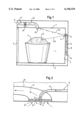
- FIG. 1 is a diagrammatic, sectional view through a first embodiment of a cooking appliance according to the invention
- FIG. 2 is a fragmented, longitudinal sectional view through a detail of a wall according to a second exemplary embodiment
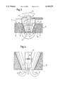
- FIG. 3 is a longitudinal sectional view through an advantageous configuration of a mouth of a feeding device according to a third exemplary embodiment.
- FIG. 4 is a longitudinal sectional view through an advantageous configuration of a sensor module corresponding to detail B of FIG. 3 and according to a fourth exemplary embodiment.
- FIG. 1 there is shown a cooking appliance that has a heatable cooking space 1, which is externally bounded by a housing formed of sides by walls 3, 5, 7 and a door 9.
- the cooking space 1 serves for receiving a cooking product 11 to be cooked.
- An air-feeding device 13 is provided in the housing 3, 5, 7, 9 of the cooking appliance.
- the device 13 has an air duct 15, which at one end opens out into the cooking space 1 at a mouth 17 through an opening in the wall 5 and at the other end has a fresh-air feeding opening 19.
- a sensor module 21 is provided in the air duct 15 in the region of the mouth opening 17. It is directed through the mouth 17 of the feeding device 13 at a surface area under measurement 23 on the surface of the cooking product 11. The measuring direction is indicated here by a dashed line 18.
- the cooking appliance also has an extraction device 25, which is mounted on the side of the top wall 7 facing away from the cooking space 1.
- the extraction device 25 has an air duct 27, which at one end opens out into the cooking space 1 at a mouth 29 and at its other end has a blowing-out opening 31 in the housing.
- the extraction device 25 also has a fan 33, which is connected to the air duct 27.
- the cooking appliance operates as follows. During the cooking operation, the sensor 21 senses the infrared radiation emitted from the surface area under measurement 23 of the cooking product 11 and passes on the sensed values to non-illustrated evaluation electronics for subsequent evaluation, in order to control the cooking operation in a way known per se according to the settings made by an operator.
- the fan 33 transports air from the mouth 29 out of the cooking space 1 through the air duct 27 to the blowing-out opening 31.
- the lines provided with arrows in the drawings indicate the flow path of the air.
- the negative pressure established in the cooking space 1 leads to further air flowing in from the fresh-air feeding opening 19 via the air duct 15 of the feeding device 13. The air thereby flows past the sensor module 21 through the mouth 17 into the cooking space 1.
- the suction of the extraction device 25 causes the air entering the cooking space 1 to be directed in the direction of the mouth 29 of the extraction device 25. On its way through the cooking space 1, it therefore follows approximately the imaginary joining line 20, represented by dotted lines, between the mouth 17 of the feeding device 13 and the mouth 29 of the extraction device 25. The air stream is thus kept at a distance from the surface area under measurement 23 and from the cooking product 11 by the extraction device 25 (FIG. 1).
- FIG. 2 shows a detail of a second exemplary embodiment.
- the extraction device 25 is configured as a water-vapor discharge.
- the mouth 29 on the cooking space side is therefore covered by a water-vapor filter 35.
- the feeding device 13 is in this case disposed in such a way that the air duct 15 opens out into the water-vapor filter 35.
- the cooling air sucked in through the feeding device 13 can in this case be used in a way known per se for cooling electrical components of the cooking appliances.
- the mouth 17 of the feeding device 13 is thus surrounded by the mouth 29 of the extraction device 25.
- the imaginary straight joining line between the two lies in the surface of the water-vapor filter 35 on the cooking space side.
- the sensor module 21 is in this case disposed inside the feeding device 13 in the water-vapor filter 35.
- the cross-sectional surface area of the mouth 29 of the extraction device 25 corresponds approximately to the surface area of the water-vapor filter 35. It is consequently significantly larger than the cross-sectional surface area of the feeding device 13 at the mouth 17 on the cooking space side. It is also advantageous if the flow velocity at the mouth 29 of the extraction device 25 is greater than that at the mouth 17 of the feeding device 13. As a result, more air is extracted via the extraction device 25 than is fed to the cooking space 1 via the feeding device 13. The cooling air blown through the mouth 17 in the top region then does not penetrate into the cooking space 1 and onto the cooking product 11 but is extracted again immediately by the fan 33.
- FIG. 3 shows an advantageous configuration of the mouth 17 of the feeding device 13 corresponding to the embodiment of FIG. 2, according to a first exemplary embodiment.
- the air duct 15 of the feeding device 13 tapers conically in its end region on the cooking space side toward the mouth 17 and is in this case formed by the water-vapor filter 35.
- the sensor module 21 is positioned with its end face 22 directly at the mouth 17. As indicated by an arrow 24 and an alternative position 21', the sensor module 21 is in this case pivotably mounted.
- the tapering has the effect of accelerating the air stream toward the mouth 17. As a result, the cooling and dirt-repelling effect of the air stream is enhanced, without increasing the volumetric flow.
- the pivotability of the sensor module 21 makes it possible to direct the end face 22 at different regions of the cooking space 1 and to perform an exact adjustment of the sensor module 21 to the surface area under measurement 23 respectively to be monitored.
- the sensor module 21 can be adapted for ensuring optimum measuring accuracy, for example when the cooking product has been pushed in at different heights.
- the freedom of movement of the sensor module 21 is in this case helped by the conical shape of the air duct 15 in the water-vapor filter 35.
- FIG. 4 shows an advantageous configuration of the sensor module 21 on an enlarged scale in a configuration according to a fourth exemplary embodiment.
- the sensor module 21, disposed in the mouth region of the feeding device 13, has on the end face 22 an aperture 37. Viewed from the cooking space 1, disposed behind the aperture 37 is a lens 39. Provided laterally in the sensor module 21 between the aperture 37 and the lens 39 are openings 41.
- the cooling air partly flows out of the air duct 15 through the lateral openings 41 into the sensor module 21 and leaves again in the direction of the cooking space 1 at the aperture 37. Therefore, the lens 39 is additionally protected against soiling and overheating.
- the pivotability of the sensor module 21 could be restricted to individual parts, such as lens optics for example.
- introduction of an air flow into the cooking space 1 could be avoided entirely.
- the cooling air would be carried away directly by the extraction device 25, without reaching the cooking space 1.
- the air feed could have a fan that actively introduces air into the cooking appliance.
Landscapes
- Engineering & Computer Science (AREA)
- Chemical & Material Sciences (AREA)
- Combustion & Propulsion (AREA)
- Mechanical Engineering (AREA)
- General Engineering & Computer Science (AREA)
- Electric Ovens (AREA)
- Radiation Pyrometers (AREA)
Applications Claiming Priority (2)
| Application Number | Priority Date | Filing Date | Title |
|---|---|---|---|
| DE19908800A DE19908800A1 (de) | 1999-03-01 | 1999-03-01 | Gargerät mit Temperatursensor |
| DE19908800 | 1999-03-01 |
Publications (1)
| Publication Number | Publication Date |
|---|---|
| US6158329A true US6158329A (en) | 2000-12-12 |
Family
ID=7899249
Family Applications (1)
| Application Number | Title | Priority Date | Filing Date |
|---|---|---|---|
| US09/516,657 Expired - Fee Related US6158329A (en) | 1999-03-01 | 2000-03-01 | Cooking appliance with temperature sensor |
Country Status (3)
| Country | Link |
|---|---|
| US (1) | US6158329A (de) |
| EP (1) | EP1033538A3 (de) |
| DE (1) | DE19908800A1 (de) |
Cited By (8)
| Publication number | Priority date | Publication date | Assignee | Title |
|---|---|---|---|---|
| US6376812B2 (en) * | 2000-04-26 | 2002-04-23 | Sanyo Electric Co., Ltd. | Cooking appliance with infrared sensor having movable field of view |
| US6555791B2 (en) * | 2000-12-15 | 2003-04-29 | Thirode Grandes Cuisines Poligny | Oven and an oven control method |
| GB2438871A (en) * | 2006-06-09 | 2007-12-12 | David Pollak | Heating and cooking appliance comprising an air extractor |
| WO2013098003A1 (en) | 2011-12-26 | 2013-07-04 | Arcelik Anonim Sirketi | Oven with infrared sensor |
| WO2013190367A3 (en) * | 2012-06-21 | 2014-02-20 | Convotherm Elektrogeräte GmbH | Cooking device comprising heat exchange means |
| US9528710B2 (en) | 2014-03-12 | 2016-12-27 | Haier U.S. Appliance Solutions, Inc. | Sensing system for a cooktop appliance with airflow protected sensor |
| US20170019959A1 (en) * | 2015-07-13 | 2017-01-19 | Samsung Electronics Co., Ltd. | Cooking apparatus |
| US9752786B2 (en) | 2014-03-12 | 2017-09-05 | Haier Us Appliance Solutions, Inc. | Sensing system for a cooktop appliance with airflow protected sensor |
Families Citing this family (4)
| Publication number | Priority date | Publication date | Assignee | Title |
|---|---|---|---|---|
| DE10211671B4 (de) * | 2002-03-15 | 2014-04-03 | Rational Ag | Verfahren und Vorrichtung zur Kühlung eines Garprozeßfühlers |
| DE102005046716B4 (de) | 2005-09-29 | 2024-05-29 | Rational Ag | Verfahren zur Steuerung oder Regelung eines Gargeräts, Infrarotmesseinrichtung zum Durchführen solch eines Verfahrens und Gargerät mit solch einer Infrarotmesseinrichtung |
| EP2149755B1 (de) | 2008-07-30 | 2012-12-05 | Electrolux Home Products Corporation N.V. | Ofen und Betriebsverfahren dafür |
| DE102013114230B4 (de) * | 2013-12-17 | 2019-09-05 | Rational Aktiengesellschaft | Gargerät mit Optik |
Citations (13)
| Publication number | Priority date | Publication date | Assignee | Title |
|---|---|---|---|---|
| US3501620A (en) * | 1964-09-05 | 1970-03-17 | Burger Eisenwerke Ag | Apparatus for thawing deep-frozen food |
| US3586516A (en) * | 1969-04-18 | 1971-06-22 | Fred C Smith | Meat defrosting apparatus |
| US4133336A (en) * | 1977-09-29 | 1979-01-09 | Smith Alva T | Ventilated stove |
| US4425720A (en) * | 1981-03-05 | 1984-01-17 | Elevitch Franklin R | Coffee roaster |
| US4455478A (en) * | 1981-11-17 | 1984-06-19 | Sunset Ltd. | Portable unit for heating packaged food |
| US5111012A (en) * | 1989-05-16 | 1992-05-05 | Samsung Electronics Co., Ltd. | Electronic microwave heating apparatus |
| US5160829A (en) * | 1991-03-25 | 1992-11-03 | Chang Kwei T | Electric heat-convection stove with transparent housing |
| US5423248A (en) * | 1989-09-22 | 1995-06-13 | Patentsmith Corporation | Air circulator for impingement heat transfer apparatus |
| US5458050A (en) * | 1993-03-01 | 1995-10-17 | Su; Johnson | Multi-purpose cooker |
| US5579679A (en) * | 1995-12-20 | 1996-12-03 | Lundar Electric Industrial Co., Ltd. | Roaster |
| US5695668A (en) * | 1995-09-08 | 1997-12-09 | Boddy; Victor R. | Oven with selectively energized heating elements |
| US5699722A (en) * | 1989-03-17 | 1997-12-23 | Erickson; Chad | Rapid cooking device |
| US5765471A (en) * | 1996-10-07 | 1998-06-16 | Monard; Ronald E. | Tortilla warming device |
Family Cites Families (5)
| Publication number | Priority date | Publication date | Assignee | Title |
|---|---|---|---|---|
| JPS5759850Y2 (de) * | 1978-07-13 | 1982-12-21 | ||
| JPS5612931A (en) * | 1979-07-13 | 1981-02-07 | Toshiba Corp | Electronic oven |
| JPS58140531A (ja) * | 1982-02-16 | 1983-08-20 | Hitachi Heating Appliance Co Ltd | 加熱調理器 |
| JPS58221326A (ja) * | 1982-06-18 | 1983-12-23 | Toshiba Corp | 加熱調理装置 |
| JPH0821631A (ja) | 1994-07-05 | 1996-01-23 | Hitachi Home Tec Ltd | 高周波加熱装置 |
-
1999
- 1999-03-01 DE DE19908800A patent/DE19908800A1/de not_active Withdrawn
-
2000
- 2000-02-28 EP EP00104087A patent/EP1033538A3/de not_active Withdrawn
- 2000-03-01 US US09/516,657 patent/US6158329A/en not_active Expired - Fee Related
Patent Citations (13)
| Publication number | Priority date | Publication date | Assignee | Title |
|---|---|---|---|---|
| US3501620A (en) * | 1964-09-05 | 1970-03-17 | Burger Eisenwerke Ag | Apparatus for thawing deep-frozen food |
| US3586516A (en) * | 1969-04-18 | 1971-06-22 | Fred C Smith | Meat defrosting apparatus |
| US4133336A (en) * | 1977-09-29 | 1979-01-09 | Smith Alva T | Ventilated stove |
| US4425720A (en) * | 1981-03-05 | 1984-01-17 | Elevitch Franklin R | Coffee roaster |
| US4455478A (en) * | 1981-11-17 | 1984-06-19 | Sunset Ltd. | Portable unit for heating packaged food |
| US5699722A (en) * | 1989-03-17 | 1997-12-23 | Erickson; Chad | Rapid cooking device |
| US5111012A (en) * | 1989-05-16 | 1992-05-05 | Samsung Electronics Co., Ltd. | Electronic microwave heating apparatus |
| US5423248A (en) * | 1989-09-22 | 1995-06-13 | Patentsmith Corporation | Air circulator for impingement heat transfer apparatus |
| US5160829A (en) * | 1991-03-25 | 1992-11-03 | Chang Kwei T | Electric heat-convection stove with transparent housing |
| US5458050A (en) * | 1993-03-01 | 1995-10-17 | Su; Johnson | Multi-purpose cooker |
| US5695668A (en) * | 1995-09-08 | 1997-12-09 | Boddy; Victor R. | Oven with selectively energized heating elements |
| US5579679A (en) * | 1995-12-20 | 1996-12-03 | Lundar Electric Industrial Co., Ltd. | Roaster |
| US5765471A (en) * | 1996-10-07 | 1998-06-16 | Monard; Ronald E. | Tortilla warming device |
Cited By (8)
| Publication number | Priority date | Publication date | Assignee | Title |
|---|---|---|---|---|
| US6376812B2 (en) * | 2000-04-26 | 2002-04-23 | Sanyo Electric Co., Ltd. | Cooking appliance with infrared sensor having movable field of view |
| US6555791B2 (en) * | 2000-12-15 | 2003-04-29 | Thirode Grandes Cuisines Poligny | Oven and an oven control method |
| GB2438871A (en) * | 2006-06-09 | 2007-12-12 | David Pollak | Heating and cooking appliance comprising an air extractor |
| WO2013098003A1 (en) | 2011-12-26 | 2013-07-04 | Arcelik Anonim Sirketi | Oven with infrared sensor |
| WO2013190367A3 (en) * | 2012-06-21 | 2014-02-20 | Convotherm Elektrogeräte GmbH | Cooking device comprising heat exchange means |
| US9528710B2 (en) | 2014-03-12 | 2016-12-27 | Haier U.S. Appliance Solutions, Inc. | Sensing system for a cooktop appliance with airflow protected sensor |
| US9752786B2 (en) | 2014-03-12 | 2017-09-05 | Haier Us Appliance Solutions, Inc. | Sensing system for a cooktop appliance with airflow protected sensor |
| US20170019959A1 (en) * | 2015-07-13 | 2017-01-19 | Samsung Electronics Co., Ltd. | Cooking apparatus |
Also Published As
| Publication number | Publication date |
|---|---|
| DE19908800A1 (de) | 2000-09-07 |
| EP1033538A3 (de) | 2004-08-25 |
| EP1033538A2 (de) | 2000-09-06 |
Similar Documents
| Publication | Publication Date | Title |
|---|---|---|
| US6158329A (en) | Cooking appliance with temperature sensor | |
| US20190247163A1 (en) | Oral scanner | |
| US8302527B2 (en) | Method for determining the variation with time of the amount of steam released from a food product during a cooking process in a cooking chamber of a baking oven | |
| KR930010263B1 (ko) | 가열장치 | |
| EP3867576B1 (de) | Eine dunstabzugshaube mit einem temperatursensor | |
| WO2017070960A1 (zh) | 空气处理装置 | |
| EP0752803B1 (de) | Einrichtung zur Vermeidung der Fehlfunktion des Sensors in Mikrowellenöfen | |
| CS208692B2 (en) | Gas detector | |
| JP5372839B2 (ja) | 誘導加熱調理器 | |
| JP4933989B2 (ja) | 誘導加熱調理器 | |
| JPH08201263A (ja) | 煙検出装置 | |
| JP2008084854A (ja) | 誘導加熱調理器 | |
| JP2012137234A (ja) | レンジフード | |
| KR200232522Y1 (ko) | 후드겸용 전자레인지의 고내공기 배출 구조 | |
| JP3828319B2 (ja) | オーブンレンジ | |
| JPH0127340B2 (de) | ||
| EP4711679A1 (de) | Kochgerät | |
| JPS5612931A (en) | Electronic oven | |
| JPH067012B2 (ja) | 調理器 | |
| CN217821367U (zh) | 一种气流温度控制装置 | |
| KR940004615B1 (ko) | 초전센서를 이용한 전자레인지의 가열상태 검출장치 | |
| TR2022019155A2 (tr) | Fanin çalişmasinin otomati̇k olarak kontrol edi̇ldi̇ği̇ bi̇r davlumbaz | |
| CN112689346B (zh) | 安装支架和烹饪器具 | |
| KR100826708B1 (ko) | 오븐의 공기 배출 시스템 | |
| KR20090086750A (ko) | 공기조화기 |
Legal Events
| Date | Code | Title | Description |
|---|---|---|---|
| AS | Assignment |
Owner name: BSH BOSCH UND SIEMENS HAUSGERATE GMBH, GERMANY Free format text: ASSIGNMENT OF ASSIGNORS INTEREST;ASSIGNORS:SCHNEIDER, MARION;THALER, MARTIN;HAS, UWE;AND OTHERS;REEL/FRAME:011153/0266;SIGNING DATES FROM 20000324 TO 20000604 |
|
| FEPP | Fee payment procedure |
Free format text: PAYOR NUMBER ASSIGNED (ORIGINAL EVENT CODE: ASPN); ENTITY STATUS OF PATENT OWNER: LARGE ENTITY |
|
| FPAY | Fee payment |
Year of fee payment: 4 |
|
| REMI | Maintenance fee reminder mailed | ||
| LAPS | Lapse for failure to pay maintenance fees | ||
| STCH | Information on status: patent discontinuation |
Free format text: PATENT EXPIRED DUE TO NONPAYMENT OF MAINTENANCE FEES UNDER 37 CFR 1.362 |
|
| FP | Lapsed due to failure to pay maintenance fee |
Effective date: 20081212 |