US6148141A - Image pickup system with separable/attachable image pickup device and display device - Google Patents
Image pickup system with separable/attachable image pickup device and display device Download PDFInfo
- Publication number
- US6148141A US6148141A US08/841,564 US84156497A US6148141A US 6148141 A US6148141 A US 6148141A US 84156497 A US84156497 A US 84156497A US 6148141 A US6148141 A US 6148141A
- Authority
- US
- United States
- Prior art keywords
- image data
- image
- compression
- image pickup
- display device
- Prior art date
- Legal status (The legal status is an assumption and is not a legal conclusion. Google has not performed a legal analysis and makes no representation as to the accuracy of the status listed.)
- Expired - Lifetime
Links
Images

Classifications
-
- H—ELECTRICITY
- H04—ELECTRIC COMMUNICATION TECHNIQUE
- H04N—PICTORIAL COMMUNICATION, e.g. TELEVISION
- H04N5/00—Details of television systems
- H04N5/76—Television signal recording
- H04N5/765—Interface circuits between an apparatus for recording and another apparatus
- H04N5/77—Interface circuits between an apparatus for recording and another apparatus between a recording apparatus and a television camera
-
- H—ELECTRICITY
- H04—ELECTRIC COMMUNICATION TECHNIQUE
- H04N—PICTORIAL COMMUNICATION, e.g. TELEVISION
- H04N19/00—Methods or arrangements for coding, decoding, compressing or decompressing digital video signals
- H04N19/60—Methods or arrangements for coding, decoding, compressing or decompressing digital video signals using transform coding
- H04N19/61—Methods or arrangements for coding, decoding, compressing or decompressing digital video signals using transform coding in combination with predictive coding
-
- H—ELECTRICITY
- H04—ELECTRIC COMMUNICATION TECHNIQUE
- H04N—PICTORIAL COMMUNICATION, e.g. TELEVISION
- H04N9/00—Details of colour television systems
- H04N9/79—Processing of colour television signals in connection with recording
- H04N9/80—Transformation of the television signal for recording, e.g. modulation, frequency changing; Inverse transformation for playback
- H04N9/82—Transformation of the television signal for recording, e.g. modulation, frequency changing; Inverse transformation for playback the individual colour picture signal components being recorded simultaneously only
- H04N9/83—Transformation of the television signal for recording, e.g. modulation, frequency changing; Inverse transformation for playback the individual colour picture signal components being recorded simultaneously only the recorded chrominance signal occupying a frequency band under the frequency band of the recorded brightness signal
- H04N9/831—Transformation of the television signal for recording, e.g. modulation, frequency changing; Inverse transformation for playback the individual colour picture signal components being recorded simultaneously only the recorded chrominance signal occupying a frequency band under the frequency band of the recorded brightness signal using intermediate digital signal processing
Definitions
- the present invention relates to an image pickup device adapted for use in a camcorder (camera-integrated video cassette recorder), a display device for displaying the picked-up image; and an image pickup system consisting of the image pickup device and the display device.
- camcorder cam-integrated video cassette recorder
- display device for displaying the picked-up image
- image pickup system consisting of the image pickup device and the display device.
- an image pickup unit and an image display unit including a monitor and a VCR are mutually inseparably integrated. For this reason, in case of image pickup by placing such camcorder in a place unreachable by the photographer, the image to be picked-up cannot be confirmed on the monitor.
- FIG. 14 there are shown an image pickup unit 10, an image display unit 11, a lens 1 for forming the image of an object, an image pickup device 2 for converting the formed image of the object into an image signal, a CDS/AGC circuit 3 for effecting sample holding of the image signal, thereby obtaining an appropriate signal level, a digital signal processing unit 4 for effecting A/D conversion on the image signal from the CDS/AGC circuit 3 and effecting digital signal processing, an NTSC encoder 5 for converting the digital image signal from the digital signal processing circuit 4 into an NTSC image signal, a cable 6 connecting the image pickup unit 10 and the image display unit 11, a monitor 7 for displaying the NTSC image signal supplied from the image pickup unit 10 or reproduced from a recording medium to be explained later, a recording/reproducing unit 8 for recording the NTSC image signal from the image pickup unit 10 on a recording medium or reproducing such signal from the recording medium, and attaching/detaching means 9a, 9b for mechanically attaching or detaching the image pickup unit 10 and the
- the image pickup operation by the image pickup unit 10 can be made while the image display unit 11 is separated, and both can be united in use, if necessary, by the attaching/detaching means 9a, 9b.
- an object of the present invention is to separate the image pickup unit and the image display unit in mutually separable and unitable manner, thereby increasing the freedom in the image pickup operation.
- Another object of the present invention is to avoid increase of the electric power consumption in attaining the above-mentioned object.
- Still another object of the present invention is to achieve efficient image transmission from the image pickup unit to the image display unit.
- an image pick-up device comprising image pickup means for pickup the image of an object and outputting image data, first compression encoding means for compression encoding of the image data, wireless transmission means for modulating thus compression encoded image data for transmission to a wireless transmission channel, and connection means adapted to be mechanically and electrically connected in detachable manner to a display device for displaying the image picked-up by the image pickup device and to transmit the above-mentioned image data from the image pickup means.
- a display device comprising wireless reception means for receiving and demodulating the compression encoded and modulated image data from the wireless transmission channel, first expansion means for expanding thus demodulated image data thereby obtaining first image data, connection means adapted to be mechanically and electrically connected in detachable manner to the image taking device and to receive second image data from the image pickup device, signal processing means for selectively receiving the first and second image data and processing thus received image data to output an image signal of a predetermined system, and display means for displaying the image signal of the above-mentioned predetermined system.
- an image pickup system comprising an image pickup device including image taking means for taking the image of an object and outputting image data, compression encoding means for compression encoding of the image data, wireless transmission means for modulating thus compression encoded image data for transmission to wireless transmission channel, and first connection means adapted to be mechanically and electrically connected in detachable manner to a display device for displaying the image picked-up by the image pickup device and to transmit the above-mentioned image data from the image pickup means; and a display device including wireless reception means for receiving and demodulating the transmitted image data from the wireless transmission channel, expansion means for expanding thus demodulated image data thereby obtaining first image data, second connection means adapted to be mechanically and electrically connected in detachable manner to the first connection means and to receive second image data from the image pickup device, signal processing means for selectively receiving the first and second image data and processing thus received image data to output an image signal of a predetermined system, and display means for displaying the image signal of the above-mentioned pre
- FIG. 1 is a block diagram showing an image pickup unit in a first embodiment of the present invention
- FIG. 2 is a block diagram showing an image display unit in the first embodiment
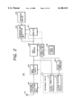
- FIG. 3 is a block diagram showing an image taking unit in a second, third or fifth embodiment
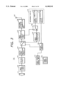
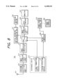
- FIG. 4 is a block diagram showing an image display unit in the second embodiment
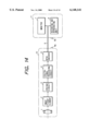
- FIG. 5 is a block diagram showing a JPEG image compression circuit
- FIG. 6 is a block diagram showing a JPEG image expansion circuit
- FIG. 7 is a block diagram showing a DV image compression circuit:
- FIG. 8 is a block diagram showing an image display unit in the third embodiment.
- FIG. 9 is a block diagram showing an image taking unit in a fourth embodiment.
- FIG. 10 is a block diagram showing an image display unit in the fourth embodiment.
- FIG. 11 is a block diagram of an MPEG image compression circuit
- FIG. 12 is a block diagram of an MPEG image expansion circuit
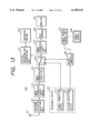
- FIG. 13 is a block diagram showing an image display unit in the fifth embodiment.
- FIG. 14 is a block diagram of a conventional camcorder.
- FIGS. 1 to 13 mutually corresponding components are represented by a same number and will not be explained repeatedly.
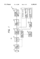
- FIG. 1 is a block diagram of an image pickup unit 100 of a camcorder in a first embodiment of the present invention
- FIG. 2 is an image display unit 200 of the camcorder.
- a lens 101 for forming the image of an object there are provided a lens 101 for forming the image of an object, an image pickup device 102 for converting thus formed image into an image signal, a CDS/AGC circuit 103 for effecting sample holding on the image signal thereby providing an appropriate signal level, a digital signal processing circuit 104 for A/D conversion of the image signal from the CDS/AGC circuit 103 and digital signal processing, an image compression circuit 105 for compression encoding of the digital image signal from the digital signal processing circuit 104, a spectrum diffusion transmission circuit 106 for transmitting the compressed image data from the image compression circuit 105 by spectrum diffusion modulation, and a transmitting antenna 107.
- a microcomputer 108 There are also provided a microcomputer 108, a power source 109, a power source control unit 110 for on/off control of the power supply to various units according to commands from the microcomputer 108, a joining detection device 112 for detecting that an image display unit 200 to be explained later is coupled, a signal connection device 113 for connecting the digital signal processing circuit 104 with the image display unit 200 when it is coupled, and an attaching/detaching device 114 including the joining detection device 112 and the signal connection device 113 and adapted to electrically and mechanically connect, in detachable manner, to the image display unit 200.
- a receiving antenna 201 for receiving the image data transmitted from the image pickup unit 100 and effecting demodulation to restore the compressed image data
- an image expansion unit 203 for expanding the compressed image data to obtain the digital image signal
- an NTSC encoder 204 for converting the digital image signal into the NTSC image signal
- a recording/reproducing unit 205 for recording and reproducing the NTSC image signal
- a recording medium 206 for recording and reproducing the NTSC image signal
- a monitor 207 for displaying the NTSC image signal.
- a microcomputer 208 There are also provided a microcomputer 208, a power source 209, a power source control unit 110 for on/off control of the power supply to various unit according to commands from the microcomputer 208, a joining detection device 211 for detecting that the image display unit 100 is coupled, a signal connection device 212 for connecting the NTSC encoder 204 with the image pickup unit 100 when it is coupled, and an attaching/detaching device 213 including the joining detection device 211 and the signal connection device 212 and adapted to electrically and mechanically connect, in detachable manner, to the image pickup unit 100.
- the image compression circuit 105 mentioned above can also be a pixel thinning-out circuit for processing the digital image signal from the digital signal processing circuit 104 in the unit of each pixel and reducing the number of pixels by pixel thinning-out.
- the image expansion circuit 203 mentioned above can also be a pixel interpolation circuit for processing the digital image signal from the spectrum diffusion reception unit 202 in the unit of each pixel to effect interpolation of the pixels.
- the image picked-up by the image pickup unit 100 is transmitted by wireless transmission to the image display unit 200 in a distant location and can be monitored and/or recorded and reproduced therein. Consequently the photographer can place the image pickup unit 100 in a distant location, without being concerned with the location of the image display unit 200, whereby freedom of the image pickup operation can be increased. It is also possible to take out the picked-up image from the signal connection device 113 and send it to an external equipment such as a computer. It is furthermore possible to supply the signal connecting device 212 of the image display unit 200 with the image signal from an external equipment, thereby monitoring and/or recording and reproducing such image signal.
- the joining detection devices 112, 211 do not detect the coupled state, so that the microcomputers 108, 208 supply the power source control units 110, 210 with commands to feed electric power to all the units.
- the joining detection devices 112, 211 detects such coupled state, whereby the microcomputers 108, 208 supply the power source control units 110, 210 with commands to terminal power supply to the spectrum diffusion transmission unit 106, the spectrum diffusion reception unit 202, the image compression circuit 105 and the image expansion circuit 203 whereupon the power supply to these circuits is terminated. In this manner the electric power consumption can be reduced in the coupled state.
- the image signal is transmitted with a reduced data amount obtained by compression, so that it can be transmitted without difficulty even by wireless digital transmission which is limited in the transmission rate. Also the use of the spectrum diffusion modulation allows transmission of the signal of a wide band with a limited electric power. On the other hand, in case the both units are mutually coupled, a high image quality can be obtained since the image signal is transmitted without compression.
- the present embodiment employs, for the image compression, the JPEG compression method and the DV compression method.
- the JPEG compression method capable of achieving a high compression rate for the image data, is suitable for image transmission in the wireless transmission channel limited in the transmission rate.
- the JPEG compression method is often employed in the personal computers as the image data format.
- the DV compression method is widely employed in the digital CVR because of very high image quality, though the image data compression rate is not so high.
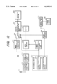
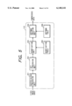
- FIG. 3 shows the image pickup unit 100 in the second embodiment
- FIG. 4 shows the image display unit 200 therein.
- a JPEG image compression circuit 115 for compressing, in the JPEG method, the digital image signal from the digital signal processing circuit 104
- a DV image compression circuit 116 for compressing, in the DV method, the digital image signal from the digital signal processing circuit 104
- a compression method selecting switch 117 for connecting the digital signal processing circuit 104 to the JPEG image compression circuit 115 or the DV image compression circuit 116 according to a command from the microcomputer 108
- a compression method selecting switch 118 shifted in linkage with the switch 117, for connecting the signal connecting device 113 to the JPEG image compression circuit 115 or the DV image compression circuit 116.
- a JPEG image expansion circuit 214 for expanding the JPEG compressed image to restore the digital image signal
- a DV image compression circuit 215 for compressing, by the DV method, the digital image signal from the JPEG image compression circuit 214
- a DV image expansion circuit 216 for expanding the DV compressed image data from the signal connecting device 212 to restore the digital image signal
- a digital recording/reproducing unit 217 for digital recording and reproduction of the DV compressed image data on or from the recording medium 206
- an image selecting switch 218 for connecting the digital recording/reproducing unit 217 to the DV image compression circuit 215 or the signal connecting device 212 according to the command from the microcomputer 208.
- the joining detection devices 112, 211 do not detect the coupled state, so that the microcomputers 108 of the Image pickup unit 100 instructs the switch 117 to connect the digital signal processing circuit 104 to the JPEG image compression circuit 115. Also linked with the switch 117, the switch 118 connects the signal connecting device 113 to the JPEG image compression circuit 115.
- the microcomputer 208 of the image display unit 200 instructs the switch 218 to connect the digital recording/reproducing unit 217 to the DV image compression circuit 215.
- the signal flows along paths of lens 101 ⁇ image pickup device 102 ⁇ CDS/AGC circuit 103 ⁇ digital signal processing circuit 104 ⁇ switch 117 ⁇ JPEG image compression circuit 115 ⁇ spectrum diffusion transmission unit 106 ⁇ transmitting antenna 107 ⁇ receiving antenna 201 ⁇ spectrum diffusion reception unit 202 ⁇ JPEG image expansion circuit 214 ⁇ DV image compression circuit 215 ⁇ switch 218 ⁇ digital recording/reproducing unit 217 ⁇ recording medium 206, and of JPEG image expansion circuit 214 ⁇ NTSC encoder 204 ⁇ monitor 207.
- the JPEG compressed signal is released from the JPEG image compression circuit 115 through the switch 118 to the signal connecting device 113, it can be transmitted for example to the computer. Also the external DV compressed signal can be supplied to the image display unit 200 through the signal connecting device 212.
- the microcomputer 208 instructs the switch 218 to connect the digital recording/reproducing unit 217 to the DV image expansion circuit 216.
- the signal flows along a path of recording medium 206 ⁇ digital recording/reproducing unit 217 ⁇ switch 218 ⁇ DV image expansion circuit 216 ⁇ NTSC encoder 204 ⁇ monitor 207.
- the joining detection devices 112, 211 detect the coupled state.
- the microcomputer 108 of the image pickup unit 100 instructs the switch 117 to connect the digital signal processing circuit 104 to the DV image compression circuit 116.
- the switch 118 connects the signal connecting device 113 to the DV image compression circuit 116.
- the microcomputer 208 of the image display unit 200 instructs the switch image selecting switch 218 to connect the digital recording/reproducing unit 217 to the signal connecting device 212.
- the signal flows along paths of lens 101 ⁇ image pickup device 102 ⁇ CDS/AGC circuit 103 ⁇ digital signal processing circuit 104 ⁇ switch 117 ⁇ DV image compression circuit 116 ⁇ switch 118 ⁇ signal connecting device 113 ⁇ signal connecting device 212 ⁇ switch 218 ⁇ digital recording/reproducing unit 217 ⁇ recording medium 206, and of signal connecting device 212 ⁇ DV image expansion circuit 216 ⁇ NTSC encoder 204 ⁇ monitor 207.
- the signal flows along a path of recording medium 206 ⁇ digital recording/reproducing unit 217 ⁇ switch 218 ⁇ DV image expansion circuit 216 ⁇ NTSC encoder 204 ⁇ monitor 207.
- the JPEG method is selected for image compression, whereby the wireless transmission can be achieved in efficient manner.
- the DV method is selected for image compression, thereby achieving digital image recording of high image quality.
- FIG. 5 is a block diagram showing the configuration of the JPEG image compression circuit 115 in FIG. 3, wherein provided are a raster-block conversion unit 301, a DCT (discrete cosine transformation) unit 302, a quantization unit 303, a Huffman encoding unit 304, a quantization table 305 to be used in the quantization unit 303, and a Huffman table 306 to be used in the Huffman encoding unit 304.
- a raster-block conversion unit 301 a DCT (discrete cosine transformation) unit 302
- a quantization unit 303 quantization unit 303
- Huffman encoding unit 304 a quantization table 305 to be used in the quantization unit 303
- a Huffman table 306 to be used in the Huffman encoding unit 304.
- the input digital image signal consisting of luminance/color difference signals of raster format is divided by the raster block conversion unit 301 into blocks of 8 ⁇ 8 pixels, each represented by an 8 ⁇ 8 square matrix.
- the DCT unit 302 executes a DCT process (discrete cosine transformation) on the 8 ⁇ 8 matrix data.
- the transformed data, called DCT coefficients are also 8 ⁇ 8 matrix data of which terms at the upper left part represent the magnitudes of the low frequency components of the original image while those at the lower right part represent the magnitudes of the high frequency components of the original image.
- the quantization unit 303 executes divisions of the data in the above-mentioned matrix respectively, utilizing a coefficient table called the quantization table 305.
- the quantization table 305 is weighted in the high frequency components with respect to the low frequency components, so that the results of the divisions constitute matrix data of which values decrease progressively toward the higher frequency. Subsequently there is executed quantization to reduce the values less than a predetermined value to zero, whereby most values in the lower right part of the matrix data become zero.
- the above-mentioned matrix data are arranged as a data train in an order called zigzag scan, and are subjected to a transformation called Huffman encoding in the Huffman encoding unit 304.
- This transformation replaces a redundant portion of the data (a data portion where a same value appears in continuation).
- the portion with value 0 in continuation is significantly shortened, whereby the amount of the image data is compressed.
- FIG. 6 is a block diagram showing the configuration of the JPEG image expansion circuit 214 in FIG. 4, wherein provided a Huffman decoding unit 401, a Huffman table 402 to be used in the Huffman decoding unit 401, an inverse quantization unit 403, a quantization table 404 for be used in the inverse quantization unit 403, an inverse DCT unit 405, and a block-raster conversion unit 406.
- the input JPEG compressed image signal is subjected to Huffman decoding in the Huffman decoding unit 401 to provide the original data train.
- This data train is returned to the matrix data, which are subjected to multiplications in the inverse quantization unit 403 based on the quantization table 404.
- the matrix data obtained in this state contain a larger number of 0 in the higher frequency components, in comparison with the aforementioned DCT coefficients.
- the inverse DCT unit 405 executes an inverse DCT and the block-raster conversion unit 406 rearranges the blocks in the original order, thereby providing the expanded digital image.
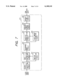
- FIG. 7 shows the configuration of the DV image compression circuit 215 in FIG. 4, wherein provided a block division shuffling circuit 501, a DCT operation weighing circuit 502, a rearrangement circuit 503, an adaptive quantization circuit 504, a variable length encoding circuit 505, a deshuffling circuit 506, a motion detection circuit 507 and a code amount estimation circuit 508.
- the data with converted transmission rate are converted, in the block division shuffling circuit 501, into blocks of 8 ⁇ 8 pixels each, in each of the luminance signal and the two color difference signals, and a macroblock is constituted by six blocks consisting of four Y signal blocks and two color difference signal blocks.
- the divided data are then subjected to a rearrangement of the positions on the image in order to average the amount of information constituting the portion of a fixed length, and are subjected to the DCT operation (discrete cosine transformation) in the DCT operation weighing circuit 502. In this operation, an image with a large amount of motion is processed within a frame, and the motion detection circuit 507 is provided for this purpose.
- the data are weighted, rearranged by the rearrangement circuit 503, and quantized by the adaptive quantization circuit 504.
- the quantized data are subjected to variable length coding (VLC) in the variable length encoding circuit 505, in such a manner that the amount of codes after variable length encoding becomes constant for every macroblock, by estimating the amount of codes at the quantization.
- VLC variable length coding
- the encoded data are outputted after being returned to the original position in the image.
- the output digital signal is given an error correction code, and deshuffled by the deshuffling circuit 506, whereby compressed data are outputted.
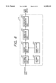
- the image pickup unit 100 is identical, in configuration, with that shown in FIG. 3 in the second embodiment, but the image display unit 200 has a configuration shown in FIG. 8, which is different in the arrangement of the various units from that shown in FIG. 4.
- the signal flows along paths of lens 101 ⁇ image pickup device 102 ⁇ CDS/AGC circuit 103 ⁇ digital signal processing circuit 104 ⁇ switch 117 ⁇ JPEG image compression circuit 115 ⁇ spectrum diffusion transmission unit 106 ⁇ transmitting antenna 107 ⁇ receiving antenna 201 ⁇ spectrum diffusion reception unit 202 ⁇ JPEG image expansion circuit 214 ⁇ DV image compression circuit 215 ⁇ switch 218 ⁇ digital recording/reproducing unit 217 ⁇ recording medium 206, and of switch 218 ⁇ DV image expansion circuit 216 ⁇ NTSC encoder 204 ⁇ monitor 207.
- the signal flows along a path of recording medium 206 ⁇ digital recording/reproducing unit 217 ⁇ DV image expansion circuit 216 ⁇ NTSC encoder 204 ⁇ monitor 207.
- the signal flows along paths of lens 101 ⁇ image pickup device 102 ⁇ CDS/AGC circuit 103 ⁇ digital signal processing circuit 104 ⁇ switch 117 ⁇ DV image compression circuit 116 ⁇ switch 118 ⁇ signal connecting device 113 ⁇ signal connecting device 212 ⁇ switch 218 ⁇ digital recording/reproducing unit 217 ⁇ recording medium 206, and of switch 218 ⁇ DV image expansion circuit 216 ⁇ NTSC encoder 204 ⁇ monitor 207.
- the signal flows along a path of recording medium 206 ⁇ digital recording/reproducing unit 217 ⁇ DV image expansion circuit 216 ⁇ NTSC encoder 204 ⁇ monitor 207.
- This embodiment employs MPEG compression method instead of the JPEG compression method in the second and third embodiments. Consequently the image pickup unit 100 is provided, as shown in FIG. 9, with an MPEG image compression circuit 119, and the image display unit 200 is provided, as shown in FIG. 10, with an MPEG image expansion circuit 219.
- the remaining parts in FIG. 9 correspond to those in FIG. 3, and the remaining parts in FIG. 10 correspond to those in FIG. 4. Also the signal paths in the recording and reproducing operations are similar to those in the configurations shown in FIGS. 3 and 4.
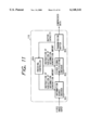
- FIG. 11 is a block diagram showing the configuration of the MPEG image compression circuit 119, wherein provided are an information source encoder 801 for compressing the amount of input information by effecting the aforementioned DCT, quantization etc., a video signal multiplexer 802 for converting thus compressed data into data based on the MPEG format, a transmission buffer 803 for transmitting the data of the above-mentioned format at a predetermined data rate, and an encoding controller 804 for increasing or decreasing the amount of the generated information.
- an information source encoder 801 for compressing the amount of input information by effecting the aforementioned DCT, quantization etc.
- a video signal multiplexer 802 for converting thus compressed data into data based on the MPEG format
- a transmission buffer 803 for transmitting the data of the above-mentioned format at a predetermined data rate
- an encoding controller 804 for increasing or decreasing the amount of the generated information.
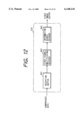
- FIG. 12 is a block diagram showing the configuration of the MPEG image expansion circuit 219, wherein provided are a reception buffer 901 for securing a decoding process time for the received data, a video signal demultiplexer 902 for extracting the compressed data from the received format data, and an information source decoder 903 for restoring the original image signal by inverse quantization, inverse DCT etc.
- the MPEG compression method is featured by executing, in the information source encoder 801, an anticipated encoding of representing the object image in the form of the difference from a past image or the difference from an anticipated image estimated from the past image, in addition to the aforementioned DCT and quantization, and can provide a higher compression rate, in comparison with the JPEG method which provides a series of compressed images each completed within an image frame.
- This embodiment employs the MPEG compression method in the third embodiment shown in FIG. 8, instead of the JPEG compression method therein. Consequently the image display unit 200 is provided with an MPEG image expansion circuit 219 but is same in other parts as the configuration shown in FIG. 8.
- the image pickup unit 100 is same as that shown in FIG. 9. Also the signal flow paths in the recording and reproducing operations are same as those in the third embodiment.
- the image pickup device when the image pickup device and the image display device are mutually separated, the image pickup device can send the compression encoded image data to the image display device by wireless transmission, without the connecting cable and with a reduced data amount, whereby the freedom of the image pickup operation can be increased. Also when the image pickup device and the image display device are integrally coupled through the connection means, the image pickup device can directly transmit the image data through the connection means.
- the JPEG compression method enables efficient transmission when the image pickup device and the image display device are mutually separated, and the DV compression method allows to improve the image quality when the devices are integrally coupled.
- the electric power consumption can be saved by interrupting the power supply to the unnecessary circuits, when the devices are integrally coupled.
Landscapes
- Engineering & Computer Science (AREA)
- Multimedia (AREA)
- Signal Processing (AREA)
- Compression Or Coding Systems Of Tv Signals (AREA)
- Studio Devices (AREA)
- Compression, Expansion, Code Conversion, And Decoders (AREA)
Priority Applications (1)
| Application Number | Priority Date | Filing Date | Title |
|---|---|---|---|
| US09/624,203 US6978085B1 (en) | 1996-05-10 | 2000-07-24 | Image pickup system with separable/attachable image pickup device and display device |
Applications Claiming Priority (4)
| Application Number | Priority Date | Filing Date | Title |
|---|---|---|---|
| JP11647996 | 1996-05-10 | ||
| JP8-116479 | 1996-05-10 | ||
| JP9-062892 | 1997-03-17 | ||
| JP6289297A JP4346697B2 (ja) | 1996-05-10 | 1997-03-17 | 撮像装置 |
Related Child Applications (1)
| Application Number | Title | Priority Date | Filing Date |
|---|---|---|---|
| US09/624,203 Division US6978085B1 (en) | 1996-05-10 | 2000-07-24 | Image pickup system with separable/attachable image pickup device and display device |
Publications (1)
| Publication Number | Publication Date |
|---|---|
| US6148141A true US6148141A (en) | 2000-11-14 |
Family
ID=26403947
Family Applications (2)
| Application Number | Title | Priority Date | Filing Date |
|---|---|---|---|
| US08/841,564 Expired - Lifetime US6148141A (en) | 1996-05-10 | 1997-04-30 | Image pickup system with separable/attachable image pickup device and display device |
| US09/624,203 Expired - Fee Related US6978085B1 (en) | 1996-05-10 | 2000-07-24 | Image pickup system with separable/attachable image pickup device and display device |
Family Applications After (1)
| Application Number | Title | Priority Date | Filing Date |
|---|---|---|---|
| US09/624,203 Expired - Fee Related US6978085B1 (en) | 1996-05-10 | 2000-07-24 | Image pickup system with separable/attachable image pickup device and display device |
Country Status (2)
| Country | Link |
|---|---|
| US (2) | US6148141A (enExample) |
| JP (1) | JP4346697B2 (enExample) |
Cited By (12)
| Publication number | Priority date | Publication date | Assignee | Title |
|---|---|---|---|---|
| US20020030750A1 (en) * | 2000-09-11 | 2002-03-14 | Koichi Mizutani | Image input apparatus that can transmit input image |
| US6377309B1 (en) * | 1999-01-13 | 2002-04-23 | Canon Kabushiki Kaisha | Image processing apparatus and method for reproducing at least an image from a digital data sequence |
| US6453072B1 (en) * | 1997-10-09 | 2002-09-17 | Olympus Optical Co., Ltd. | Image coding system |
| US6549243B1 (en) * | 1997-08-21 | 2003-04-15 | Hitachi, Ltd. | Digital broadcast receiver unit |
| US20040091240A1 (en) * | 2002-11-11 | 2004-05-13 | Canon Kabushiki Kaisha | Image processing apparatus and method |
| US6965728B1 (en) * | 1999-08-05 | 2005-11-15 | Sanyo Electric Co., Ltd. | Digital recording apparatus |
| US20060282865A1 (en) * | 1998-12-08 | 2006-12-14 | Canon Kabushiki Kaisha | Receiving apparatus and method |
| US20110128414A1 (en) * | 2003-12-24 | 2011-06-02 | Walker Digital, Llc | Method and apparatus for automatically capturing and managing images |
| US8538247B2 (en) | 2009-08-17 | 2013-09-17 | Canon Kabushiki Kaisha | Image processing apparatus and image processing method |
| US8558921B2 (en) | 2002-12-18 | 2013-10-15 | Walker Digital, Llc | Systems and methods for suggesting meta-information to a camera user |
| CN105745916A (zh) * | 2013-11-19 | 2016-07-06 | 索尼公司 | 成像系统、成像装置、信息处理装置和方法以及程序 |
| US20170048380A1 (en) * | 2014-06-17 | 2017-02-16 | Sony Corporation | Imaging system, imaging device, information processing device, method, and program |
Families Citing this family (9)
| Publication number | Priority date | Publication date | Assignee | Title |
|---|---|---|---|---|
| KR100567576B1 (ko) * | 1998-12-31 | 2006-06-16 | 삼성테크윈 주식회사 | 디지탈 씨씨디 카메라의 무선 영상 신호 송신 장치 |
| DE60038552T2 (de) * | 2000-08-08 | 2009-05-28 | Thomson Multimedia | Tragbares Videoaufnahmesystem |
| US7372999B2 (en) * | 2002-09-09 | 2008-05-13 | Ricoh Company, Ltd. | Image coder and image decoder capable of power-saving control in image compression and decompression |
| JP4618676B2 (ja) | 2005-04-28 | 2011-01-26 | 株式会社リコー | 構造化文書符号の転送方法、画像処理システム、サーバ装置、プログラム及び情報記録媒体 |
| US7804435B2 (en) * | 2006-08-31 | 2010-09-28 | Ati Technologies Ulc | Video decoder with reduced power consumption and method thereof |
| JP2008293044A (ja) * | 2008-08-12 | 2008-12-04 | Seiko Epson Corp | 表示装置および表示装置の制御方法 |
| JP2008310355A (ja) * | 2008-08-12 | 2008-12-25 | Seiko Epson Corp | 表示装置および表示装置の制御方法 |
| JP5435971B2 (ja) * | 2009-01-29 | 2014-03-05 | キヤノン株式会社 | 通信装置 |
| US8750674B2 (en) | 2011-09-26 | 2014-06-10 | Intellectual Ventures Fund 83 Llc | Remotely controllable digital video camera system |
Citations (9)
| Publication number | Priority date | Publication date | Assignee | Title |
|---|---|---|---|---|
| US4864589A (en) * | 1985-07-24 | 1989-09-05 | Nec Home Electronics Ltd. | Spread spectrum power line communications |
| US5091787A (en) * | 1987-05-06 | 1992-02-25 | Fuji Photo Film Co., Ltd. | Memory cartridge-connectable electronic device such as electronic still video camera |
| EP0501699A2 (en) * | 1991-02-27 | 1992-09-02 | General Electric Company | Apparatus for segmenting encoded video signals for transmission |
| US5170262A (en) * | 1985-09-13 | 1992-12-08 | Canon Kabushiki Kaisha | Electronic camera |
| US5381179A (en) * | 1989-03-30 | 1995-01-10 | Canon Kabushiki Kaisha | Camera-integrated video recorder apparatus |
| US5568205A (en) * | 1993-07-26 | 1996-10-22 | Telex Communications, Inc. | Camera mounted wireless audio/video transmitter system |
| US5734787A (en) * | 1994-03-19 | 1998-03-31 | Sony Corporation | Optical disk having a particular format to store user-selected data, such as compressed video data or computed files, including a dedicated TOC region and an application TOC to identify the video compression format |
| US5754227A (en) * | 1994-09-28 | 1998-05-19 | Ricoh Company, Ltd. | Digital electronic camera having an external input/output interface through which the camera is monitored and controlled |
| US5956372A (en) * | 1994-03-17 | 1999-09-21 | Digital Compression Technology, L.P. | Coding system for digital transmission compression |
-
1997
- 1997-03-17 JP JP6289297A patent/JP4346697B2/ja not_active Expired - Fee Related
- 1997-04-30 US US08/841,564 patent/US6148141A/en not_active Expired - Lifetime
-
2000
- 2000-07-24 US US09/624,203 patent/US6978085B1/en not_active Expired - Fee Related
Patent Citations (9)
| Publication number | Priority date | Publication date | Assignee | Title |
|---|---|---|---|---|
| US4864589A (en) * | 1985-07-24 | 1989-09-05 | Nec Home Electronics Ltd. | Spread spectrum power line communications |
| US5170262A (en) * | 1985-09-13 | 1992-12-08 | Canon Kabushiki Kaisha | Electronic camera |
| US5091787A (en) * | 1987-05-06 | 1992-02-25 | Fuji Photo Film Co., Ltd. | Memory cartridge-connectable electronic device such as electronic still video camera |
| US5381179A (en) * | 1989-03-30 | 1995-01-10 | Canon Kabushiki Kaisha | Camera-integrated video recorder apparatus |
| EP0501699A2 (en) * | 1991-02-27 | 1992-09-02 | General Electric Company | Apparatus for segmenting encoded video signals for transmission |
| US5568205A (en) * | 1993-07-26 | 1996-10-22 | Telex Communications, Inc. | Camera mounted wireless audio/video transmitter system |
| US5956372A (en) * | 1994-03-17 | 1999-09-21 | Digital Compression Technology, L.P. | Coding system for digital transmission compression |
| US5734787A (en) * | 1994-03-19 | 1998-03-31 | Sony Corporation | Optical disk having a particular format to store user-selected data, such as compressed video data or computed files, including a dedicated TOC region and an application TOC to identify the video compression format |
| US5754227A (en) * | 1994-09-28 | 1998-05-19 | Ricoh Company, Ltd. | Digital electronic camera having an external input/output interface through which the camera is monitored and controlled |
Cited By (31)
| Publication number | Priority date | Publication date | Assignee | Title |
|---|---|---|---|---|
| US20050110905A1 (en) * | 1997-08-21 | 2005-05-26 | Satoru Takashimizu | Digital broadcast receiver unit |
| US7436458B2 (en) | 1997-08-21 | 2008-10-14 | Hitachi, Ltd. | Digital broadcast receiver unit |
| US7889281B2 (en) | 1997-08-21 | 2011-02-15 | Hitachi Consumer Electronics Co., Ltd. | Digital broadcast receiver unit |
| US6549243B1 (en) * | 1997-08-21 | 2003-04-15 | Hitachi, Ltd. | Digital broadcast receiver unit |
| US8913197B2 (en) | 1997-08-21 | 2014-12-16 | Hitachi Maxell, Ltd. | Digital broadcast receiver unit |
| US20040233332A1 (en) * | 1997-08-21 | 2004-11-25 | Satoru Takashimizu | Digital broadcast receiver unit |
| US8345168B2 (en) | 1997-08-21 | 2013-01-01 | Hitachi Consumer Electronics Co., Ltd. | Digital broadcast receiver unit |
| US7173674B2 (en) * | 1997-08-21 | 2007-02-06 | Hitachi, Ltd. | Digital broadcast receiver unit |
| US6453072B1 (en) * | 1997-10-09 | 2002-09-17 | Olympus Optical Co., Ltd. | Image coding system |
| US20060282865A1 (en) * | 1998-12-08 | 2006-12-14 | Canon Kabushiki Kaisha | Receiving apparatus and method |
| US20060282874A1 (en) * | 1998-12-08 | 2006-12-14 | Canon Kabushiki Kaisha | Receiving apparatus and method |
| US7788690B2 (en) | 1998-12-08 | 2010-08-31 | Canon Kabushiki Kaisha | Receiving apparatus and method |
| US8081870B2 (en) | 1998-12-08 | 2011-12-20 | Canon Kabushiki Kaisha | Receiving apparatus and method |
| US6377309B1 (en) * | 1999-01-13 | 2002-04-23 | Canon Kabushiki Kaisha | Image processing apparatus and method for reproducing at least an image from a digital data sequence |
| US6965728B1 (en) * | 1999-08-05 | 2005-11-15 | Sanyo Electric Co., Ltd. | Digital recording apparatus |
| US7139021B2 (en) * | 2000-09-11 | 2006-11-21 | Canon Kabushiki Kaisha | Image input apparatus that can transmit input image |
| US20020030750A1 (en) * | 2000-09-11 | 2002-03-14 | Koichi Mizutani | Image input apparatus that can transmit input image |
| US7706583B2 (en) * | 2002-11-11 | 2010-04-27 | Canon Kabushiki Kaisha | Image processing apparatus and method |
| US20040091240A1 (en) * | 2002-11-11 | 2004-05-13 | Canon Kabushiki Kaisha | Image processing apparatus and method |
| US8558921B2 (en) | 2002-12-18 | 2013-10-15 | Walker Digital, Llc | Systems and methods for suggesting meta-information to a camera user |
| US9288375B2 (en) * | 2003-12-24 | 2016-03-15 | Inventor Holdings, Llc | Method and apparatus for automatically capturing and managing images |
| US8466987B2 (en) * | 2003-12-24 | 2013-06-18 | Walker Digital, Llc. | Automatic capture and management of images |
| US20110128414A1 (en) * | 2003-12-24 | 2011-06-02 | Walker Digital, Llc | Method and apparatus for automatically capturing and managing images |
| US8538247B2 (en) | 2009-08-17 | 2013-09-17 | Canon Kabushiki Kaisha | Image processing apparatus and image processing method |
| CN105745916A (zh) * | 2013-11-19 | 2016-07-06 | 索尼公司 | 成像系统、成像装置、信息处理装置和方法以及程序 |
| US20160295090A1 (en) * | 2013-11-19 | 2016-10-06 | Sony Corporation | Imaging system, imaging device, information processing device and method, and program |
| EP3073723A4 (en) * | 2013-11-19 | 2017-06-21 | Sony Corporation | Imaging system, imaging device, information processing device, method, and program |
| US9883091B2 (en) * | 2013-11-19 | 2018-01-30 | Sony Corporation | Device control based on attachment/detachment information |
| CN105745916B (zh) * | 2013-11-19 | 2019-10-29 | 索尼公司 | 成像系统、成像装置、信息处理装置和方法以及程序 |
| US20170048380A1 (en) * | 2014-06-17 | 2017-02-16 | Sony Corporation | Imaging system, imaging device, information processing device, method, and program |
| US9973616B2 (en) * | 2014-06-17 | 2018-05-15 | Sony Corporation | Imaging system, imaging device, information processing device, method, and program |
Also Published As
| Publication number | Publication date |
|---|---|
| US6978085B1 (en) | 2005-12-20 |
| JP4346697B2 (ja) | 2009-10-21 |
| JPH1028236A (ja) | 1998-01-27 |
Similar Documents
| Publication | Publication Date | Title |
|---|---|---|
| US6148141A (en) | Image pickup system with separable/attachable image pickup device and display device | |
| KR100781629B1 (ko) | Dct 베이스 기술을 사용하여 압축된 정보를 기억함에 의해 압축 해제에 필요한 메모리를 감축하는 방법 및 이 방법을 구현하기 위한 디코더 | |
| JP2883449B2 (ja) | 記録装置 | |
| AU8751398A (en) | Video transmission apparatus employing intra-frame-only video compression that is mpeg-2 compatible | |
| US7672569B2 (en) | Moving picture recording and sending device having zoom processing capability | |
| JP3864494B2 (ja) | 画像信号変換装置およびそれを使用したテレビ受信機 | |
| KR960013742B1 (ko) | 상이한 압축 방법에 따라 압축된 화상 데이타를 기록/재생하기 위한 기록/재생 장치 및 방법 | |
| US6330695B1 (en) | Data communications apparatus, data communications method, program for coding information data contained in computer readable medium | |
| US5963678A (en) | Image signal processing apparatus and method | |
| JP2002044531A (ja) | 撮像装置、画像記録装置、画像記録/再生装置及び画像伝送方法 | |
| JP3630879B2 (ja) | ビデオカメラ | |
| JP3406924B2 (ja) | 画像処理装置及びその方法 | |
| RU2191483C2 (ru) | Видеокамера | |
| JP3153950B2 (ja) | 画像圧縮符号化装置及び画像圧縮復号化装置 | |
| US5905840A (en) | Method and apparatus for recording and playing back digital video signal | |
| JP4215835B2 (ja) | 画像記録再生装置及び画像記録再生方法 | |
| JPH10336537A (ja) | 無線受信装置及び方法 | |
| WO2000004716A1 (en) | Image pickup device | |
| JP3501505B2 (ja) | 画像形成装置及び画像処理装置 | |
| JP2856556B2 (ja) | 記録再生装置 | |
| JP3601771B2 (ja) | ディジタル信号記録装置及びディジタル信号記録方法 | |
| JP3087563B2 (ja) | ディジタル画像データの伝送装置 | |
| JP3628069B2 (ja) | 画像データ処理装置および方法ならびに画像データ記録装置および方法ならびに画像データ再生装置および方法 | |
| KR100727906B1 (ko) | 단말기를 이용한 감시 카메라 신호처리장치 및 그 방법 | |
| JP3034923B2 (ja) | 画像データ記録再生装置 |
Legal Events
| Date | Code | Title | Description |
|---|---|---|---|
| AS | Assignment |
Owner name: CANON KABUSHIKI KAISHA, JAPAN Free format text: ASSIGNMENT OF ASSIGNORS INTEREST;ASSIGNORS:MAEDA, MASAMINE;TAKAHASHI, KAZUHIRO;ARAI, HIDEYUKI;AND OTHERS;REEL/FRAME:008795/0195;SIGNING DATES FROM 19970609 TO 19970611 |
|
| STCF | Information on status: patent grant |
Free format text: PATENTED CASE |
|
| FEPP | Fee payment procedure |
Free format text: PAYOR NUMBER ASSIGNED (ORIGINAL EVENT CODE: ASPN); ENTITY STATUS OF PATENT OWNER: LARGE ENTITY |
|
| FPAY | Fee payment |
Year of fee payment: 4 |
|
| FPAY | Fee payment |
Year of fee payment: 8 |
|
| FPAY | Fee payment |
Year of fee payment: 12 |