US6035693A - System for detecting abnormality of yaw rate sensor and lateral acceleration sensor - Google Patents
System for detecting abnormality of yaw rate sensor and lateral acceleration sensor Download PDFInfo
- Publication number
- US6035693A US6035693A US09/138,530 US13853098A US6035693A US 6035693 A US6035693 A US 6035693A US 13853098 A US13853098 A US 13853098A US 6035693 A US6035693 A US 6035693A
- Authority
- US
- United States
- Prior art keywords
- yaw rate
- lateral acceleration
- vehicle speed
- abnormality
- sensor
- Prior art date
- Legal status (The legal status is an assumption and is not a legal conclusion. Google has not performed a legal analysis and makes no representation as to the accuracy of the status listed.)
- Expired - Fee Related
Links
Images


Classifications
-
- B—PERFORMING OPERATIONS; TRANSPORTING
- B60—VEHICLES IN GENERAL
- B60T—VEHICLE BRAKE CONTROL SYSTEMS OR PARTS THEREOF; BRAKE CONTROL SYSTEMS OR PARTS THEREOF, IN GENERAL; ARRANGEMENT OF BRAKING ELEMENTS ON VEHICLES IN GENERAL; PORTABLE DEVICES FOR PREVENTING UNWANTED MOVEMENT OF VEHICLES; VEHICLE MODIFICATIONS TO FACILITATE COOLING OF BRAKES
- B60T8/00—Arrangements for adjusting wheel-braking force to meet varying vehicular or ground-surface conditions, e.g. limiting or varying distribution of braking force
- B60T8/32—Arrangements for adjusting wheel-braking force to meet varying vehicular or ground-surface conditions, e.g. limiting or varying distribution of braking force responsive to a speed condition, e.g. acceleration or deceleration
- B60T8/88—Arrangements for adjusting wheel-braking force to meet varying vehicular or ground-surface conditions, e.g. limiting or varying distribution of braking force responsive to a speed condition, e.g. acceleration or deceleration with failure responsive means, i.e. means for detecting and indicating faulty operation of the speed responsive control means
- B60T8/885—Arrangements for adjusting wheel-braking force to meet varying vehicular or ground-surface conditions, e.g. limiting or varying distribution of braking force responsive to a speed condition, e.g. acceleration or deceleration with failure responsive means, i.e. means for detecting and indicating faulty operation of the speed responsive control means using electrical circuitry
-
- B—PERFORMING OPERATIONS; TRANSPORTING
- B60—VEHICLES IN GENERAL
- B60G—VEHICLE SUSPENSION ARRANGEMENTS
- B60G2400/00—Indexing codes relating to detected, measured or calculated conditions or factors
- B60G2400/05—Attitude
- B60G2400/052—Angular rate
- B60G2400/0523—Yaw rate
-
- B—PERFORMING OPERATIONS; TRANSPORTING
- B60—VEHICLES IN GENERAL
- B60G—VEHICLE SUSPENSION ARRANGEMENTS
- B60G2600/00—Indexing codes relating to particular elements, systems or processes used on suspension systems or suspension control systems
- B60G2600/08—Failure or malfunction detecting means
-
- B—PERFORMING OPERATIONS; TRANSPORTING
- B60—VEHICLES IN GENERAL
- B60G—VEHICLE SUSPENSION ARRANGEMENTS
- B60G2800/00—Indexing codes relating to the type of movement or to the condition of the vehicle and to the end result to be achieved by the control action
- B60G2800/80—Detection or control after a system or component failure
-
- B—PERFORMING OPERATIONS; TRANSPORTING
- B60—VEHICLES IN GENERAL
- B60T—VEHICLE BRAKE CONTROL SYSTEMS OR PARTS THEREOF; BRAKE CONTROL SYSTEMS OR PARTS THEREOF, IN GENERAL; ARRANGEMENT OF BRAKING ELEMENTS ON VEHICLES IN GENERAL; PORTABLE DEVICES FOR PREVENTING UNWANTED MOVEMENT OF VEHICLES; VEHICLE MODIFICATIONS TO FACILITATE COOLING OF BRAKES
- B60T2270/00—Further aspects of brake control systems not otherwise provided for
- B60T2270/40—Failsafe aspects of brake control systems
- B60T2270/411—Offset failure
-
- B—PERFORMING OPERATIONS; TRANSPORTING
- B60—VEHICLES IN GENERAL
- B60T—VEHICLE BRAKE CONTROL SYSTEMS OR PARTS THEREOF; BRAKE CONTROL SYSTEMS OR PARTS THEREOF, IN GENERAL; ARRANGEMENT OF BRAKING ELEMENTS ON VEHICLES IN GENERAL; PORTABLE DEVICES FOR PREVENTING UNWANTED MOVEMENT OF VEHICLES; VEHICLE MODIFICATIONS TO FACILITATE COOLING OF BRAKES
- B60T2270/00—Further aspects of brake control systems not otherwise provided for
- B60T2270/40—Failsafe aspects of brake control systems
- B60T2270/413—Plausibility monitoring, cross check, redundancy
Definitions
- the present invention relates to a system for detecting an abnormality of a yaw rate sensor for detecting a yaw rate of a vehicle, and a system for detecting an abnormality of a lateral acceleration sensor for detecting a lateral acceleration of the vehicle.
- the yaw rate sensor To detect the abnormality of the yaw rate sensor, it is a conventional practice to determine that the yaw rate is abnormal when the value detected by the yaw rate sensor exceeds an upper limit value or a lower limit value, and to determine the abnormality of the yaw rate sensor by comparison of the yaw rate presumed from a difference between left and right wheel speeds with the value detected by the yaw rate sensor.
- the technique for determining whether the yaw rate sensor is abnormal based on whether the value detected by the yaw rate sensor exceeds the upper or lower limit value, it is impossible to detect a state in which the neutral point of the yaw rate sensor is normal, but the sensitivity is abnormal.
- the technique for determining whether the yaw rate sensor is abnormal by the comparison of the yaw rate presumed from a difference between the left and right wheel speeds with the value detected by the yaw rate sensor, the yaw rate presumed from the difference between the left and right wheel speeds is inaccurate when the vehicle is traveling on a rough road or on a road surface having a low friction coefficient, on which the wheel is liable to slip. For this reason, it is impossible to determine the abnormality of the yaw rate sensor with good accuracy.
- the present invention has been accomplished with such circumstance in view, and it is a first object of the present invention to provide a system for detecting an abnormality of a yaw rate, wherein the abnormality of a yaw rate sensor, including a state in which the neutral point of the yaw rate sensor is normal, but the sensitivity is abnormal, can be detected with good accuracy, irrespective of the situation of a road surface traveled. It is a second object of the present invention to provide a system for detecting an abnormality of a lateral acceleration sensor, wherein the abnormality of the lateral acceleration sensor can be detected with good accuracy, based on the measure enabling the abnormality of the yaw rate sensor to be detected with good accuracy.
- a system for detecting an abnormality of a yaw rate sensor comprising a vehicle speed detecting means for detecting a vehicle speed of a vehicle, a dividing means for dividing the vehicle speed detected by the vehicle speed detecting means by a minimum turning radius of the vehicle, a dividing means for dividing a gravitational acceleration by the vehicle speed detected by the vehicle speed detecting means, a low-select means for selecting a lower one of outputs from both of the dividing means, and an abnormality determining means for determining that a yaw rate sensor is abnormal when the yaw rate detected by the yaw rate sensor exceeds a value selected by the low-select means.
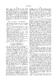
- the yaw rate ⁇ of the vehicle When there is no side-slip of the vehicle, the yaw rate ⁇ of the vehicle must be within an obliquely-lined range shown in FIG. 3 depending upon a limit value of centripetal acceleration of the vehicle, i.e., the gravitational acceleration G and a lower limit value of the radius of turning of the vehicle, i.e., the minimum turning radius R. If the vehicle speed is represented by V, the yaw rate ⁇ of the vehicle capable of being generated must be in a range of ⁇ min ⁇ (V/R), (G/V) ⁇ .
- the yaw rate ⁇ is in a range which exceeds lower one of a value (V/R) obtained by dividing the vehicle speed V by the minimum radius R of turning of the vehicle and a value (G/V) obtained by dividing the gravitational acceleration G by the vehicle speed V, i.e., which exceeds min ⁇ (V/R), (G/V) ⁇ , the side-slip of the vehicle is nearly "0" in a usual traveling state of the vehicle. Therefore, the abnormality of the yaw rate sensor, including the state in which the neutral point is normal, but the sensitivity is abnormal, can be detected with good accuracy, irrespective of the situation of the road surface traveled.
- a system for detecting an abnormality of a yaw rate sensor comprising a vehicle speed detecting means for detecting a vehicle speed of a vehicle, a steering angle sensor for detecting a steering angle of a steering wheel, a multiplying means for multiplying the steering angle detected by the steering angle sensor by the vehicle speed detected by the vehicle speed detecting means and by a given constant, a dividing means for dividing a gravitational acceleration by the vehicle speed detected by the vehicle speed detecting means, a low-select means for selecting a lower one of outputs from the multiplying means and the dividing means, and an abnormality determining means for determining that a yaw rate sensor is abnormal when a yaw rate detected by the yaw rate sensor exceeds a value selected by the low-select means.
- the yaw rate ⁇ is in a range which exceeds a lower one of a value ( ⁇ V ⁇ k) obtained by multiplying the steering angle ⁇ by the vehicle speed V and the given constant k and a value (G/V) obtained by dividing the gravitational acceleration G by the vehicle speed, i.e., which exceeds min ⁇ ( ⁇ V ⁇ k), (G/V) ⁇ , the side-slip of the vehicle is nearly "0" in a normal traveling state. Therefore, the abnormality of the yaw rate sensor, including the state in which the neutral point is normal, but the sensitivity is abnormal, can be detected with a good accuracy, irrespective of the situation of a road surface traveled.
- a system for detecting an abnormality of a yaw rate sensor comprising a vehicle speed detecting means for detecting a vehicle speed of a vehicle, a lateral acceleration sensor for detecting a lateral acceleration of the vehicle, a dividing means for dividing the vehicle speed detected by the vehicle speed detecting means by a minimum turning radius of the vehicle, a dividing means for dividing the lateral acceleration detected by the lateral acceleration sensor by the vehicle speed detected by the vehicle speed detecting means, a low-select means for selecting a lower one of outputs from both of the dividing means, and an abnormality determining means for determining that a yaw rate sensor is abnormal when a yaw rate detected by the yaw rate sensor exceeds the value selected by the low-select means.
- the range of yaw rate capable of being actually produced can be determined more precisely than the obliquely lined range shown in FIG. 3 by replacing (G/V) in FIG. 3 by ( ⁇ /V). Therefore, when the yaw rate ⁇ is in a range which exceeds lower one of a value (V/R) obtained by dividing the vehicle speed V by the minimum radius of turning of the vehicle and a value ( ⁇ /V) obtained by dividing the lateral acceleration ⁇ by the vehicle speed V, i.e., which exceeds min ⁇ (V/R), ( ⁇ /V) ⁇ , the side-slip of the vehicle is nearly "0" in a usual traveling state.
- the abnormality of the yaw rate sensor including the state in which the neutral point is normal, but the sensitivity is abnormal, can be detected with a good accuracy, irrespective of the situation of a road surface traveled.
- a system for detecting an abnormality of a yaw rate sensor comprising a vehicle speed detecting means for detecting a vehicle speed of a vehicle, a steering angle sensor for detecting a steering angle of a steering wheel, a lateral acceleration sensor for detecting a lateral acceleration of the vehicle, a multiplying means for multiplying the steering angle detected by the steering angle sensor by the vehicle speed detected by the vehicle speed detecting means and by a given constant, a dividing means for dividing the lateral acceleration detected by the lateral acceleration sensor by the vehicle speed detected by the vehicle speed detecting means, a low-select means for selecting a lower one of outputs from the multiplying means and the dividing means, and an abnormality determining means for determining that a yaw rate sensor is abnormal when a yaw rate detected by the yaw rate sensor exceeds the value selected by the low-select means.
- the radius of turning of the vehicle is capable of being presumed with ⁇ 1/( ⁇ k) ⁇ , until the centripetal acceleration becomes a limit value.
- the range of yaw rate ⁇ capable of being actually produced can be determined more precisely than the obliquely-lined range shown in FIG. 3.
- the range of yaw rate capable of actually being produced can be determined more precisely than the obliquely-lined range shown in FIG. 3 by replacing (G/R) in FIG. 3 by ( ⁇ /V).
- the yaw rate ⁇ is in a range which exceeds a lower one of a value ( ⁇ V ⁇ k) obtained by multiplying the steering angle ⁇ by the vehicle speed V and the given constant k and a value ( ⁇ /V) obtained by dividing the lateral acceleration ⁇ by the vehicle speed V, i.e., which exceeds min ⁇ ( ⁇ V ⁇ k), ( ⁇ /V) ⁇ , the side slip of the vehicle is nearly "0" in a normal traveling state.
- the abnormality of the yaw rate sensor including the state in which the neutral point is normal, but the sensitivity is abnormal, can be detected with a good accuracy, irrespective of the situation of a road surface traveled.
- a system for detecting an abnormality of a lateral acceleration sensor comprising a vehicle speed detecting means for detecting a vehicle speed of a vehicle, a dividing means for dividing a squared value of the vehicle speed detected by the vehicle speed detecting means by a minimum turning radius of the vehicle, a low-select means for selecting lower one of an output from the dividing means and a gravitational acceleration, and an abnormality determining means for determining that the lateral acceleration sensor is abnormal when the lateral acceleration detected by the lateral acceleration sensor exceeds a value selected by the low-select means.
- a system for detecting an abnormality of a lateral acceleration sensor comprising a vehicle speed detecting means for detecting a vehicle speed of a vehicle, a steering angle sensor for detecting a steering angle of a steering wheel, a multiplying means for multiplying the steering angle detected by the steering angle sensor by a squared value of the vehicle speed detected by the vehicle speed detecting means and by a given constant, a low-select means for selecting lower one of an output from the multiplying means and a gravitational acceleration, and an abnormality determining means for determining that the lateral acceleration sensor is abnormal when a lateral acceleration detected by the lateral acceleration sensor exceeds a value selected by the low-select means.
- the steering angle detected by the steering angle sensor is represented by ⁇ , and a constant is by k
- the turning radius of the vehicle is capable of being presumed with ⁇ 1/( ⁇ k) ⁇ , until the centripetal acceleration becomes a limit value.
- the lateral acceleration ⁇ is in a range which exceeds a lower one of a value obtained by multiplying the steering angle ⁇ by a squared value (V 2 ) of the vehicle and the given constant k and a gravitational acceleration G, i.e., which exceeds min ⁇ ( ⁇ V 2 ⁇ k), G ⁇
- the side-slip of the vehicle is nearly "0" in a normal traveling state of the vehicle.
- the abnormality of the yaw rate sensor including the state in which the neutral point is normal, but the sensitivity is abnormal, can be detected with high accuracy, irrespective of the situation of a road surface traveled.
- the abnormality determining means determines that the lateral acceleration sensor is abnormal when a lateral acceleration detected by the lateral acceleration sensor exceeds the output from the low-select means, both of when the vehicle is being turned leftwards and rightwards.
- An offset value component corresponding to the sloping of a road surface is included in the value detected by the lateral acceleration sensor. If the output from the low-select means is compared only with the value detected by the lateral acceleration sensor there is a possibility that the erroneous-determination may be made due to the value detected by the lateral acceleration sensor and including the offset value component. However, it is determined that the lateral acceleration sensor is abnormal when the abnormality determining means determines the abnormality, both of when the vehicle is being turned leftwards and rightwards. Therefore, the erroneous-determination due to the sloping of the road surface can be avoided, whereby the abnormality of the lateral acceleration sensor can be determined with good accuracy.
- FIG. 1 is a diagram showing a driving system and a brake system of a vehicle according to a first embodiment of the present invention.
- FIG. 2 is a block diagram of an arrangement for determining abnormalities of a yaw rate sensor and a lateral acceleration sensor, which is extracted from a control unit.
- FIG. 3 is a diagram showing a range of yaw rate which is capable of actually being generated.
- FIG. 4 is a block diagram similar to FIG. 2, but according to a second embodiment of the present invention.
- FIG. 5 is a block diagram similar to FIG. 2, but according to a third embodiment of the present invention.
- FIG. 6 is a block diagram similar to FIG. 2, but according to a fourth embodiment of the present invention.
- FIG. 7 is a block diagram similar to FIG. 2, but according to a fifth embodiment of the present invention.
- FIG. 8 is a flow chart showing a procedure for determining an abnormality of a lateral acceleration sensor.
- FIGS. 1 to 3 show a first embodiment of the present invention.
- FIG. 1 is a diagram showing a driving system and a brake system of a vehicle;
- FIG. 2 is a block diagram of an arrangement for determining an abnormality of a yaw rate sensor and a lateral acceleration sensor, which is extracted from a control unit;
- FIG. 3 is a diagram showing a range of yaw rate which is capable of being actually generated.
- the vehicle is a front engine, front drive vehicle.
- a power unit P comprising an engine E and a transmission T is mounted at a front portion of a vehicle body 1 to drive a left front wheel W FL and a right front wheel W FR which are driving wheels.
- Left and right front wheel brakes B FL and B FR are mounted on the left and right front wheels W FL and W FR , respectively, and left and right rear wheel brakes B RL and B RR are mounted on left and right rear wheels W RL and W RR which are follower wheels, respectively.
- Each of the wheel brakes B FL , B FR , B RL and B RR is, for example, a disc brake.
- a braking liquid pressure corresponding to an operation of depression of a brake pedal 3 is outputted from first and second output ports 2A and 2B provided in a tandem-type master cylinder M.
- the first and second output ports 2A and 2B are connected to a braking liquid pressure control device 4 as a vehicle motion regulating means, so that the braking liquid pressure from the braking liquid pressure control device 4 is applied to the wheel brakes B FL , B FR , B RL and B RR .
- the braking fluid pressure applied to the wheel brakes B FL , B FR , B RL and B RR is controlled by a control unit 5.
- Inputted to the control unit 5 are detection values which are detected by wheel speed sensors 6 FL , 6 FR , 6 RL and 6 RR for detecting wheel speeds of the wheels W FL , W FR , W RL and W RR , respectively, a steering angle sensor 7 for detecting a steering angle ⁇ s resulting from the operation of a steering wheel H, a yaw rate sensor 8 for detecting a yaw rate ⁇ of the vehicle, and a lateral acceleration sensor 9 for detecting a lateral acceleration ⁇ of the vehicle.
- the control unit 5 is capable of carrying out (1) an antilock brake control for controlling the braking liquid pressures for the wheel brakes B FL , B FR , B RL and B RR to eliminate the locking of the wheels during a braking operation; (2) a traction control for controlling the braking liquid pressures for the left and right front wheel brakes B FL and B FR , which are mounted on the left and right front wheels W FL and W FR , which are driving wheels, thereby inhibiting the generation of excessive slipping of the left and right front wheels W FL and W FR during non-braking operation; and (3) a directional stability control for controlling the braking liquid pressures for the left and right front wheel brakes B FL and B FR irrespective of whether during the braking and non-braking operations to control the yaw motion of the vehicle.
- a reference speed is determined for at least one of the driving wheels W FL and W FR and the follower wheels W RL and W RR ; and a control quantity is calculated based on a deviation between the actual wheel speed of at least one of the driving wheels W FL and W FR and the follower wheels W RL and W RR and the reference speed, and the operation of the braking liquid pressure control device 4 is controlled based on the control quantity.
- the reference value is corrected based on at least one of the yaw rate ⁇ and the lateral acceleration ⁇ .
- the reference value is corrected to be decreased when at least one of the yaw rate ⁇ and the lateral acceleration ⁇ is larger.
- the braking liquid pressure control device 4 and a means for regulating the output from the engine E may be used as a motion regulating means for varying the motion of the vehicle, or a means for regulating the output from the engine E may be used in place of the braking liquid pressure control device 4.
- the control unit 5 also has a function for detecting an abnormality of the yaw rate sensor 8 and the lateral acceleration sensor 9.
- the control unit 5 includes a vehicle speed presuming means 11 as a vehicle speed detecting means, a first dividing means 12, a second dividing means 13, a low-select means 14 for selecting lower one of outputs from the first and second dividing means 12 and 13, a yaw rate sensor abnormality determining means 15 for determining the abnormality of the yaw rate sensor 8 based on the output from the low-select means 14 and the yaw rate ⁇ detected by the yaw rate sensor 8, a third dividing means 16, a low-select means 17 for selecting a lower one of an output from the third dividing means 16 and a gravitational acceleration G, and a lateral acceleration sensor abnormality determining means 18 for determining the abnormality of the lateral acceleration sensor 9 based on an
- the vehicle speed presuming means, 11 presumes a vehicle speed V based on the wheel speeds of at least the left and right follower wheels, i.e., the left and right rear wheels W RL and W RR .
- a vehicle speed V based on the wheel speeds detected by the wheel speed sensors 6 FL , 6 FR , 6 RL and 6 RR is calculated in the vehicle speed presuming means 11, and the vehicle speed V obtained in the vehicle speed presuming means 11 is inputted to the first, second and third dividing means 12, 13 and 16.
- the first dividing means 12 carries out the calculation of dividing the vehicle speed V by the minimum turning radius R of the vehicle
- the second dividing means 13 carries out the calculation of dividing the gravitational acceleration G by the vehicle speed V.
- a value (V/R) obtained in the first dividing means 12 and a value (G/V) obtained in the second dividing means 13 are inputted to the low-select means 14, and a lower one of the values (V/R) and (G/V) is selected by the low-select means 14 and inputted to the yaw rate sensor abnormality determining means 15.
- a yaw rate ⁇ detected by the yaw rate sensor 8 is also inputted to the yaw rate sensor abnormality determining means 15.
- the yaw rate sensor abnormality determining means 15 determines that the yaw rate sensor 8 is abnormal, thereby outputting a signal indicative of the fact that the yaw rate sensor 8 is abnormal.
- the third dividing means 16 carries out the calculation of dividing a squared value (V 2 ) of the vehicle speed V by the minimum turning radius R of the vehicle.
- a value (V 2 /R) obtained in the third dividing means 16 and the gravitational acceleration G are inputted to the low-select means 17.
- the low-select means 17 selects a lower one of the value (V 2 /R) obtained in the third dividing means 16 and the gravitational acceleration G, and the value obtained in the low-select means 17, i.e., min ⁇ (V 2 /R), G ⁇ is inputted to the lateral acceleration sensor abnormality determining means 18.
- a lateral acceleration ⁇ detected by the lateral acceleration sensor 9 is also inputted to the lateral acceleration sensor abnormality determining means 18.
- the lateral acceleration sensor abnormality determining means 18 determines that the lateral acceleration sensor 9 is abnormal, thereby outputting a signal indicative of the fact that the lateral acceleration sensor 9 is abnormal.
- the yaw rate ⁇ of the vehicle When there is no side-slipping of the vehicle, the yaw rate ⁇ of the vehicle must be within an obliquely-lined range shown in FIG. 3, depending upon a limit value of centripetal acceleration of the vehicle, i.e., the gravitational acceleration G of the vehicle and a lower limit value of the radius of turning of the vehicle, i.e., the minimum turning radius R, and thus, a relation, ⁇ min ⁇ (V/R), (G/V) ⁇ must be established. If ⁇ >min ⁇ (V/R), (G/V) ⁇ , the yaw rate sensor 8 outputs a value which cannot be intrinsically produced.
- the side-slip of the vehicle is nearly "zero" in a normal traveling state and hence, the abnormality of the yaw rate sensor 8 including a state in which a neutral point is normal, but the sensitivity is abnormal, can be detected with a good accuracy, irrespective of the situation of a road surface traveled.
- ⁇ min ⁇ (V/R), (G/V) ⁇ is replaced by the lateral acceleration ⁇
- a relation, ⁇ min ⁇ (V 2 /R), G ⁇ is given. Therefore, the lateral acceleration ⁇ capable of being generated in the vehicle must be in a range of ⁇ min ⁇ (V 2 /R), G ⁇ .
- ⁇ >min ⁇ (V 2 /R), G ⁇ the lateral acceleration sensor 9 outputs a value which cannot be intrinsically produced.
- the abnormality of the lateral acceleration sensor 9 including a state in which a neutral point is normal, but the sensitivity is abnormal, can be detected with good accuracy, irrespective of the situation of a road surface traveled.
- FIG. 4 shows a second embodiment of the present invention, wherein portions or components corresponding to those in the first embodiment are designated by like reference characters.
- the control unit 5 includes a vehicle speed presuming means 11, a multiplying means 19, a dividing means 13, a low-select means 20 for selecting a lower one of outputs from the multiplying means 19 and the dividing means 13, a yaw rate sensor abnormality determining means 21 for determining the abnormality of the yaw rate sensor 8 based on an output from the low-select means 20 and a yaw rate detected by the yaw rate sensor 8, a dividing means 16, a low-select means 17 for selecting a lower one of an output from the dividing means 16 and the gravitational acceleration G, and a lateral acceleration sensor abnormality determining means 18 for determining the abnormality of the lateral acceleration sensor 9 based on an output from the low-select means 17 and the lateral acceleration ⁇ detected by the lateral acceleration sensor 9.
- the steering angle ⁇ detected by the steering angle sensor 7 and the vehicle speed V obtained in the vehicle speed presuming means 11 are inputted to the multiplying means 19.
- the multiplying means 19 carries out the calculation of multiplying the steering angle ⁇ by the vehicle speed V and a given constant k, and the low-select means 20 selects a lower one of a value ( ⁇ V ⁇ k) obtained in the multiplying means 19 and a value (G/V) obtained in the dividing means 13, and inputs such lower one to the yaw rate sensor abnormality determining means 21.
- the yaw rate sensor abnormality determining means 21 determines that the yaw rate sensor 8 is abnormal, thereby outputting a signal indicative of the fact that the yaw rate sensor 8 is abnormal.
- the turning radius of the vehicle is capable of being presumed with ⁇ 1/( ⁇ k) ⁇ , until the centripetal acceleration becomes a limit value.
- a range of yaw rate ⁇ capable of being actually produced can be determined more precisely than the obliquely-lined range shown in FIG. 3 by replacing (V/R) in FIG. 3 by ( ⁇ V ⁇ k). Therefore, in the second embodiment in which, when ⁇ >min ⁇ ( ⁇ V ⁇ k), (G/V) ⁇ , it is determined that the yaw rate sensor 8 is abnormal, the abnormality of the yaw rate sensor 8 can be detected with greater accuracy.
- FIG. 5 shows a third embodiment of the present invention, where portions or components corresponding to those in each of the above-described embodiments are designated by like reference characters.
- the control unit 5 includes a vehicle speed presuming means 11, dividing means 12 and 22, a low-select means 23 for selecting lower one of outputs from both the dividing means 12 and 22, a yaw rate sensor abnormality determining means 24 for determining the abnormality of the yaw rate sensor 8 based on an output from the low-select means 23 and a yaw rate ⁇ detected by the yaw rate sensor 8, a dividing means 16, a low-select means 17 for selecting lower one of an output from the dividing means 16 and the gravitational acceleration G, and a lateral acceleration sensor abnormality determining means 18 for determining the abnormality of the lateral acceleration sensor 9 based on an output from the low-select means 17 and the lateral acceleration ⁇ detected by the lateral acceleration sensor 9.
- the vehicle speed V obtained in the vehicle speed presuming means 12 and the lateral acceleration ⁇ detected by the lateral acceleration sensor 9 are inputted to the dividing means 22.
- the dividing means 22 carries out the calculation of dividing the lateral acceleration ⁇ by the vehicle speed V.
- the low-select means 23 selects a lower one of a value (V/R) obtained in one of the dividing means 12 and a value ( ⁇ /V) obtained in the other dividing means 22, and inputs such lower one to the yaw rate sensor abnormality determining means 24.
- yaw rate sensor abnormality determining means 24 a value outputted from the low-select means 23, i.e., min ⁇ (V/R), ( ⁇ /V) ⁇ and the yaw rate ⁇ detected by the yaw rate sensor 8 are compared with each other. If ⁇ >min ⁇ (V/R), ( ⁇ /V) ⁇ , the yaw rate sensor abnormality determining means 24 determines that the yaw rate sensor 8 is abnormal, thereby outputting a signal indicative of the fact that the yaw rate sensor 8 is abnormal.
- (G/R) is based on the limit value of the lateral acceleration ⁇ and hence, a range of yaw rate ⁇ capable of being actually produced can be determined more precisely than the obliquely-lined range shown in FIG. 3. Therefore, in the third embodiment in which when ⁇ >min ⁇ (V/R), ( ⁇ /V) ⁇ , it is determined that the yaw rate sensor 8 is abnormal, the abnormality of the yaw rate sensor 8 can be detected with greater accuracy.
- FIG. 6 show a fourth embodiment of the present invention, wherein portions or components corresponding to those in each of the above-described embodiments are designated by like reference characters.
- the control unit 5 includes a vehicle speed presuming means 11, a multiplying means 19, a dividing means 22, a low-select means 25 for selecting lower one of outputs from the multiplying means 19 and the dividing means 22, a yaw rate sensor abnormality determining means 26 for determining the abnormality of the yaw rate sensor 8 based on an output from the low-select means 25 and a yaw rate ⁇ detected by the yaw rate sensor 8, a dividing means 16, a low-select means 17 for selecting lower one of an output from the dividing means 16 and the gravitational acceleration G, and a lateral acceleration sensor abnormality determining means 18 for determining the abnormality of the lateral acceleration sensor 9 based on an output from the low-select means 17 and the lateral acceleration ⁇ detected by the lateral acceleration sensor 9.
- the yaw rate sensor abnormality determining means 26 determines that the yaw rate sensor 8 is abnormal, thereby outputting a signal indicative of the fact that the yaw rate sensor 8 is abnormal.
- FIGS. 7 and 8 show a fifth embodiment of the present invention, wherein portions or components corresponding to those in each of the above-described embodiments are designated by like reference characters.
- the control unit 5 includes a vehicle speed presuming means 11, a multiplying means 19, a dividing means 22, a low-select means 25 for selecting lower one of outputs from the multiplying means 19 and the dividing means 22, a yaw rate sensor abnormality determining means 26 for determining the abnormality of the yaw rate sensor 8 based on an output from the low-select means 25 and a yaw rate ⁇ detected by the yaw rate sensor 8, a multiplying means 27, a low-select means 28 for selecting a lower one of an output from the multiplying means 27 and the gravitational acceleration G, and a lateral acceleration sensor abnormality determining means 29 for determining the abnormality of the lateral acceleration sensor 9 based on an output from the low-select means 28 and the lateral acceleration ⁇ detected by the lateral acceleration sensor 9.
- the vehicle speed V obtained in the vehicle speed presuming means 11 and the steering angle ⁇ detected by the steering angle sensor 7 are inputted to the multiplying means 27.
- the multiplying means 27 the calculation of multiplying the steering angle ⁇ by a squared value (V 2 ) of the vehicle speed V and a given constant k is carried out.
- the low-select means 28 selects a lower one of a value ( ⁇ V 2 ⁇ k) obtained in the multiplying means 27 and the gravitational acceleration G, and inputs such lower one to the lateral acceleration sensor abnormality determining means 29.
- Step S1 it is determined whether the lateral acceleration ⁇ is greater than zero.
- ⁇ >0 indicates a state in which the vehicle is being turned rightwards
- ⁇ 0 indicates a state in which the vehicle is being turned leftwards
- Step S2 it is determined whether the lateral acceleration ⁇ is greater than the output min ⁇ ( ⁇ V 2 ⁇ k), G ⁇ from the low-select means 28. If it is determined at Step S2 that ⁇ >min ⁇ ( ⁇ V 2 ⁇ k), G ⁇ , a right abnormality flag is set at "1" at Step S3. Namely, it is determined that lateral acceleration sensor 9 is abnormal, when the vehicle is being turned rightwards.
- Step S4 it is determined whether a left abnormality flag is at "1". If the left abnormality flag is at "1”, it is determined at Step S5 that the lateral acceleration sensor 9 is abnormal.
- Step S1 If it is determined at Step S1 that ⁇ 0, i.e., it is determined that the vehicle is being turned leftwards, or is traveling straight, the process is advanced from Step S1 to Step S6, at which it is determined whether the lateral acceleration ⁇ is less than a value [-min ⁇ ( ⁇ V 2 ⁇ k), G ⁇ ] obtained by adding a minus sign to the output from the low-select means 28. If it is determined that ⁇ -min ⁇ ( ⁇ V 2 ⁇ k), G ⁇ , the left abnormality flag is set at "1" at Step S7. Namely, it is determined that the lateral acceleration sensor 9 is abnormal, when the vehicle is being turned leftwards.
- Step S8 it is determined whether the right abnormality flag is at "1". If the right abnormality flag is at "1", it is determined at Step S5 that the lateral acceleration sensor 9 is abnormal.
- Step S2 when it is determined at Step S2 that ⁇ min ⁇ ( ⁇ V 2 ⁇ k), G ⁇ ; (2) when it is determined at Step S4 that the left abnormality flag is at "0"; (3) when it is determined at Step S6 that ⁇ -min ⁇ ( ⁇ V 2 ⁇ k), G ⁇ ; (4) when it is determined at Step S8 that the right abnormality flag is at "0"; and (5) after it is determined at Step S5 that the lateral acceleration sensor 9 is abnormal, the process is advanced to Step S9. When it is confirmed at Step S9 that a given time has elapsed, both of the left and right flags are reset at Step S10.
- a range of yaw rate ⁇ capable of being actually produced can be determined more precisely than the obliquely-lined range shown in FIG. 3.
- the accuracy of the detection of the abnormality of the lateral acceleration sensor 9 is enhanced.
- an offset value component corresponding to an inclination of a road surface is included in the value obtained in the lateral acceleration sensor 9.
- the lateral acceleration sensor abnormality determining means 29 determines that the lateral acceleration sensor 9 is abnormal, both of when the vehicle is being turned leftwards and rightwards, the lateral acceleration sensor abnormality determining means 29 determines that the lateral acceleration sensor 9 is abnormal. Therefore, the erroneous determination due to the sloping of the road surface can be avoided, whereby abnormality of the lateral acceleration sensor 9 can be detected with greater accuracy.
Priority Applications (2)
| Application Number | Priority Date | Filing Date | Title |
|---|---|---|---|
| US09/495,330 US6276188B1 (en) | 1997-09-02 | 2000-02-01 | System for detecting abnormality of yaw rate sensor and lateral acceleration sensor |
| US09/495,331 US6260405B1 (en) | 1997-09-02 | 2000-02-01 | System for detecting abnormality of yaw rate sensor and lateral acceleration sensor |
Applications Claiming Priority (2)
| Application Number | Priority Date | Filing Date | Title |
|---|---|---|---|
| JP23664397A JP3284086B2 (ja) | 1997-09-02 | 1997-09-02 | ヨーレートセンサおよび横方向加速度センサの異常検出装置 |
| JP9-236643 | 1997-09-02 |
Related Child Applications (2)
| Application Number | Title | Priority Date | Filing Date |
|---|---|---|---|
| US09/495,331 Division US6260405B1 (en) | 1997-09-02 | 2000-02-01 | System for detecting abnormality of yaw rate sensor and lateral acceleration sensor |
| US09/495,330 Division US6276188B1 (en) | 1997-09-02 | 2000-02-01 | System for detecting abnormality of yaw rate sensor and lateral acceleration sensor |
Publications (1)
| Publication Number | Publication Date |
|---|---|
| US6035693A true US6035693A (en) | 2000-03-14 |
Family
ID=17003669
Family Applications (3)
| Application Number | Title | Priority Date | Filing Date |
|---|---|---|---|
| US09/138,530 Expired - Fee Related US6035693A (en) | 1997-09-02 | 1998-08-24 | System for detecting abnormality of yaw rate sensor and lateral acceleration sensor |
| US09/495,330 Expired - Lifetime US6276188B1 (en) | 1997-09-02 | 2000-02-01 | System for detecting abnormality of yaw rate sensor and lateral acceleration sensor |
| US09/495,331 Expired - Lifetime US6260405B1 (en) | 1997-09-02 | 2000-02-01 | System for detecting abnormality of yaw rate sensor and lateral acceleration sensor |
Family Applications After (2)
| Application Number | Title | Priority Date | Filing Date |
|---|---|---|---|
| US09/495,330 Expired - Lifetime US6276188B1 (en) | 1997-09-02 | 2000-02-01 | System for detecting abnormality of yaw rate sensor and lateral acceleration sensor |
| US09/495,331 Expired - Lifetime US6260405B1 (en) | 1997-09-02 | 2000-02-01 | System for detecting abnormality of yaw rate sensor and lateral acceleration sensor |
Country Status (2)
| Country | Link |
|---|---|
| US (3) | US6035693A (ja) |
| JP (1) | JP3284086B2 (ja) |
Cited By (8)
| Publication number | Priority date | Publication date | Assignee | Title |
|---|---|---|---|---|
| DE10113772B4 (de) * | 2000-03-21 | 2006-08-24 | Toyota Jidosha K.K., Toyota | Vorrichtung zum Erfassen einer Abnormität eines Fahrzeugsensors |
| US20110066320A1 (en) * | 2009-08-24 | 2011-03-17 | Robert Bosch Gmbh | Good checking for vehicle longitudinal acceleration sensor |
| US20110066319A1 (en) * | 2009-08-24 | 2011-03-17 | Robert Bosch Gmbh | Good checking for vehicle wheel speed sensors |
| US20110066321A1 (en) * | 2009-08-24 | 2011-03-17 | Robert Bosch Gmbh | Good checking for vehicle yaw rate sensor |
| US20110071727A1 (en) * | 2009-08-24 | 2011-03-24 | Robert Bosch Gmbh | Good checking for vehicle steering angle sensor |
| US20110071726A1 (en) * | 2009-08-24 | 2011-03-24 | Robert Bosch Gmbh | Good checking for vehicle lateral acceleration sensor |
| US20110068913A1 (en) * | 2009-08-24 | 2011-03-24 | Robert Bosch Gmbh | Good checking for vehicle pressure sensor |
| US20160163128A1 (en) * | 2013-07-17 | 2016-06-09 | Hitachi Automotive Systems, Ltd. | Vehicle control device |
Families Citing this family (11)
| Publication number | Priority date | Publication date | Assignee | Title |
|---|---|---|---|---|
| JP4127062B2 (ja) * | 2003-01-22 | 2008-07-30 | トヨタ自動車株式会社 | 横加速度センサのドリフト量推定装置、横加速度センサの出力補正装置及び路面摩擦状態推定装置 |
| JP3991978B2 (ja) * | 2003-12-12 | 2007-10-17 | 株式会社デンソー | 車両用角速度センサの補正診断装置 |
| US7522985B2 (en) * | 2003-12-12 | 2009-04-21 | Siemens Aktiengesellschaft | Method and arrangement for monitoring a measuring device located in a wheeled vehicle |
| EP1698903B1 (en) * | 2003-12-26 | 2012-10-17 | Bosch Corporation | Failure diagnosis device for vehicle body acceleration sensor and anti-lock brake system |
| JP4392599B2 (ja) * | 2004-03-25 | 2010-01-06 | 株式会社デンソー | センサシステム |
| US8061459B2 (en) * | 2006-01-17 | 2011-11-22 | GM Global Technology Operations LLC | Traction control method for a tracked vehicle |
| JP4827629B2 (ja) * | 2006-06-21 | 2011-11-30 | 本田技研工業株式会社 | 横加速度センサの故障検知装置 |
| KR100851384B1 (ko) | 2006-12-12 | 2008-08-08 | 현대자동차주식회사 | 이에스씨 신호를 이용한 씨디씨 센서의 고장 진단방법 |
| JP2009067377A (ja) * | 2007-08-21 | 2009-04-02 | Denso Corp | 車両判定装置 |
| JP4968097B2 (ja) * | 2008-02-12 | 2012-07-04 | 株式会社アドヴィックス | 異常判定装置及び異常判定方法 |
| US8886471B2 (en) | 2008-06-26 | 2014-11-11 | Infineon Technologies Ag | Rotation sensing method and system |
Citations (1)
| Publication number | Priority date | Publication date | Assignee | Title |
|---|---|---|---|---|
| US5219212A (en) * | 1991-06-05 | 1993-06-15 | Hitachi, Ltd. | Anti-skid control system for vehicle |
Family Cites Families (3)
| Publication number | Priority date | Publication date | Assignee | Title |
|---|---|---|---|---|
| JP2638990B2 (ja) * | 1988-08-31 | 1997-08-06 | 日産自動車株式会社 | 四輪駆動車の駆動力配分制御装置 |
| JPH0239167U (ja) * | 1988-09-09 | 1990-03-15 | ||
| JPH10129439A (ja) * | 1996-10-25 | 1998-05-19 | Aisin Seiki Co Ltd | 車両の運動制御装置 |
-
1997
- 1997-09-02 JP JP23664397A patent/JP3284086B2/ja not_active Expired - Fee Related
-
1998
- 1998-08-24 US US09/138,530 patent/US6035693A/en not_active Expired - Fee Related
-
2000
- 2000-02-01 US US09/495,330 patent/US6276188B1/en not_active Expired - Lifetime
- 2000-02-01 US US09/495,331 patent/US6260405B1/en not_active Expired - Lifetime
Patent Citations (1)
| Publication number | Priority date | Publication date | Assignee | Title |
|---|---|---|---|---|
| US5219212A (en) * | 1991-06-05 | 1993-06-15 | Hitachi, Ltd. | Anti-skid control system for vehicle |
Cited By (14)
| Publication number | Priority date | Publication date | Assignee | Title |
|---|---|---|---|---|
| DE10113772B4 (de) * | 2000-03-21 | 2006-08-24 | Toyota Jidosha K.K., Toyota | Vorrichtung zum Erfassen einer Abnormität eines Fahrzeugsensors |
| US20110066320A1 (en) * | 2009-08-24 | 2011-03-17 | Robert Bosch Gmbh | Good checking for vehicle longitudinal acceleration sensor |
| US20110066319A1 (en) * | 2009-08-24 | 2011-03-17 | Robert Bosch Gmbh | Good checking for vehicle wheel speed sensors |
| US20110066321A1 (en) * | 2009-08-24 | 2011-03-17 | Robert Bosch Gmbh | Good checking for vehicle yaw rate sensor |
| US20110071727A1 (en) * | 2009-08-24 | 2011-03-24 | Robert Bosch Gmbh | Good checking for vehicle steering angle sensor |
| US20110071726A1 (en) * | 2009-08-24 | 2011-03-24 | Robert Bosch Gmbh | Good checking for vehicle lateral acceleration sensor |
| US20110068913A1 (en) * | 2009-08-24 | 2011-03-24 | Robert Bosch Gmbh | Good checking for vehicle pressure sensor |
| US8401730B2 (en) | 2009-08-24 | 2013-03-19 | Robert Bosch Llc | Good checking for vehicle lateral acceleration sensor |
| US8467929B2 (en) | 2009-08-24 | 2013-06-18 | Robert Bosch Gmbh | Good checking for vehicle wheel speed sensors |
| US8494708B2 (en) * | 2009-08-24 | 2013-07-23 | Robert Bosch Gmbh | Good checking for vehicle yaw rate sensor |
| US8738219B2 (en) | 2009-08-24 | 2014-05-27 | Robert Bosch Gmbh | Good checking for vehicle longitudinal acceleration sensor |
| US8754764B2 (en) | 2009-08-24 | 2014-06-17 | Robert Bosch Gmbh | Good checking for vehicle pressure sensor |
| US8935037B2 (en) | 2009-08-24 | 2015-01-13 | Robert Bosch Gmbh | Good checking for vehicle steering angle sensor |
| US20160163128A1 (en) * | 2013-07-17 | 2016-06-09 | Hitachi Automotive Systems, Ltd. | Vehicle control device |
Also Published As
| Publication number | Publication date |
|---|---|
| US6276188B1 (en) | 2001-08-21 |
| JP3284086B2 (ja) | 2002-05-20 |
| JPH1183895A (ja) | 1999-03-26 |
| US6260405B1 (en) | 2001-07-17 |
Similar Documents
| Publication | Publication Date | Title |
|---|---|---|
| US6035693A (en) | System for detecting abnormality of yaw rate sensor and lateral acceleration sensor | |
| US6223116B1 (en) | Wheel slip angle detecting system for vehicle | |
| US4794539A (en) | Propulsion control using steering angle and vehicle speed to determine tolerance range | |
| JP3245689B2 (ja) | 車両の片揺れ動作に関して走行状態を検出する方法 | |
| US6283560B2 (en) | Braking force angular slip control system | |
| KR100511142B1 (ko) | 차량운동을나타내는운동변수제어방법및장치 | |
| JPH10504785A (ja) | 自動車のブレーキ装置 | |
| EP1760451A1 (en) | Method and system for road surface friction coefficient estimation | |
| US6349998B1 (en) | Method of controlling the travel behavior of a vehicle | |
| US5700074A (en) | Braking force distribution control system for vehicle | |
| US6427130B1 (en) | Method and device for regulating a quantity of motion representing the movement of a vehicle | |
| US6266599B1 (en) | Method and device for adjusting an amount of movement representing the vehicle motion | |
| US6349256B1 (en) | Turning behavior state detecting system for vehicle | |
| JP3410112B2 (ja) | 4輪駆動車の疑似車速算出方法 | |
| JP3039071B2 (ja) | 車両旋回限界判定装置 | |
| JP3236391B2 (ja) | 4輪駆動車の車体速度算出方法 | |
| US6742851B1 (en) | Method and device for detecting a braking situation | |
| JP4004184B2 (ja) | 車輪速異常検出装置 | |
| US6129424A (en) | Over-steering inhibiting control system for a vehicle | |
| JP3426513B2 (ja) | 車両のオーバーステア状態検出装置 | |
| US5803557A (en) | Anti-lock brake control system for vehicle | |
| JPH0611514A (ja) | 角速度検出方法及びその装置並びにアンチスキッド制御装置 | |
| JP3426512B2 (ja) | 車両の旋回挙動状態検出装置 | |
| JPH04271211A (ja) | 電動車両 | |
| JPH0740043B2 (ja) | 横加速度センサ出力値補正装置 |
Legal Events
| Date | Code | Title | Description |
|---|---|---|---|
| AS | Assignment |
Owner name: HONDA GIKEN KOGYO KABUSHIKI KAISHA, JAPAN Free format text: ASSIGNMENT OF ASSIGNORS INTEREST;ASSIGNOR:HORIUCHI, YUTAKA;REEL/FRAME:009543/0873 Effective date: 19980924 |
|
| FPAY | Fee payment |
Year of fee payment: 4 |
|
| FPAY | Fee payment |
Year of fee payment: 8 |
|
| FEPP | Fee payment procedure |
Free format text: PAYOR NUMBER ASSIGNED (ORIGINAL EVENT CODE: ASPN); ENTITY STATUS OF PATENT OWNER: LARGE ENTITY |
|
| REMI | Maintenance fee reminder mailed | ||
| LAPS | Lapse for failure to pay maintenance fees | ||
| STCH | Information on status: patent discontinuation |
Free format text: PATENT EXPIRED DUE TO NONPAYMENT OF MAINTENANCE FEES UNDER 37 CFR 1.362 |
|
| FP | Lapsed due to failure to pay maintenance fee |
Effective date: 20120314 |