US6033262A - Contact spring - Google Patents
Contact spring Download PDFInfo
- Publication number
- US6033262A US6033262A US08/904,000 US90400097A US6033262A US 6033262 A US6033262 A US 6033262A US 90400097 A US90400097 A US 90400097A US 6033262 A US6033262 A US 6033262A
- Authority
- US
- United States
- Prior art keywords
- detent
- spring
- detent sleeve
- housing
- contact
- Prior art date
- Legal status (The legal status is an assumption and is not a legal conclusion. Google has not performed a legal analysis and makes no representation as to the accuracy of the status listed.)
- Expired - Fee Related
Links
- 238000003780 insertion Methods 0.000 claims abstract description 34
- 230000037431 insertion Effects 0.000 claims abstract description 34
- 239000011800 void material Substances 0.000 claims abstract description 17
- 238000007789 sealing Methods 0.000 claims description 29
- 210000000078 claw Anatomy 0.000 description 4
- 238000009413 insulation Methods 0.000 description 3
- 210000002105 tongue Anatomy 0.000 description 3
- 229910000906 Bronze Inorganic materials 0.000 description 2
- 239000010974 bronze Substances 0.000 description 2
- 239000004020 conductor Substances 0.000 description 2
- KUNSUQLRTQLHQQ-UHFFFAOYSA-N copper tin Chemical compound [Cu].[Sn] KUNSUQLRTQLHQQ-UHFFFAOYSA-N 0.000 description 2
- 239000000463 material Substances 0.000 description 2
- 239000002184 metal Substances 0.000 description 2
- 238000000034 method Methods 0.000 description 2
- 238000005192 partition Methods 0.000 description 2
- ATJFFYVFTNAWJD-UHFFFAOYSA-N Tin Chemical compound [Sn] ATJFFYVFTNAWJD-UHFFFAOYSA-N 0.000 description 1
- 238000010276 construction Methods 0.000 description 1
- 238000006073 displacement reaction Methods 0.000 description 1
- 239000011810 insulating material Substances 0.000 description 1
- 238000012986 modification Methods 0.000 description 1
- 230000004048 modification Effects 0.000 description 1
Images
Classifications
-
- H—ELECTRICITY
- H01—ELECTRIC ELEMENTS
- H01R—ELECTRICALLY-CONDUCTIVE CONNECTIONS; STRUCTURAL ASSOCIATIONS OF A PLURALITY OF MUTUALLY-INSULATED ELECTRICAL CONNECTING ELEMENTS; COUPLING DEVICES; CURRENT COLLECTORS
- H01R13/00—Details of coupling devices of the kinds covered by groups H01R12/70 or H01R24/00 - H01R33/00
- H01R13/40—Securing contact members in or to a base or case; Insulating of contact members
- H01R13/42—Securing in a demountable manner
- H01R13/428—Securing in a demountable manner by resilient locking means on the contact members; by locking means on resilient contact members
- H01R13/434—Securing in a demountable manner by resilient locking means on the contact members; by locking means on resilient contact members by separate resilient locking means on contact member, e.g. retainer collar or ring around contact member
-
- H—ELECTRICITY
- H01—ELECTRIC ELEMENTS
- H01R—ELECTRICALLY-CONDUCTIVE CONNECTIONS; STRUCTURAL ASSOCIATIONS OF A PLURALITY OF MUTUALLY-INSULATED ELECTRICAL CONNECTING ELEMENTS; COUPLING DEVICES; CURRENT COLLECTORS
- H01R13/00—Details of coupling devices of the kinds covered by groups H01R12/70 or H01R24/00 - H01R33/00
- H01R13/40—Securing contact members in or to a base or case; Insulating of contact members
- H01R13/42—Securing in a demountable manner
- H01R13/436—Securing a plurality of contact members by one locking piece or operation
- H01R13/4361—Insertion of locking piece perpendicular to direction of contact insertion
- H01R13/4362—Insertion of locking piece perpendicular to direction of contact insertion comprising a temporary and a final locking position
Definitions
- the invention relates to contact springs. More specifically, the invention pertains to a contact spring with a base spring which on one end has a connecting part for an electrical power cord and on the other has a contact part with at least two spring arms, and having a detent sleeve, seated on the base spring, as a detent-type aid in retaining the contact spring inside a surrounding housing.
- the contact spring comprises a base spring, from which two spring arms of a contact part extend integrally away on one end, and a contact pin can be inserted between the two spring arms.
- the other end of the base spring is adjoined by a connecting part for an electrical power cord.
- the connecting part can be a crimp connection with a conductor wire claw and an insulation claw, which are clamped onto an electrical power cord or its sheathing.
- a detent sleeve also called an overspring, is seated on the base spring.
- the function of the detent sleeve is essentially to increase the spring force of the contact spring, and by being embodied with one or more detent tongues, to enable a disconnectable locking of the contact spring in an associated contact chamber of a surrounding housing made of insulating material.
- the detent sleeve as a rule comprises a material with good spring properties, while the base spring is made from a material with good electrical and thermal properties.
- the detent sleeve can for example be made from a sheet metal as a stamped and bent part.
- the base spring is preferably also a stamped and bent part, but because of the requisite good electrical properties it preferably comprises tin bronze or so-called spring bronze.
- Plug connectors must often be dustproof and/or splashproof.
- sealing plates such as rubber plates.
- the contact springs must be passed through these sealing plates, which are disposed on the surrounding housing.
- sealing plates become damaged especially whenever the contact elements have to be passed through this sealing plate multiple times in both directions, as can be the case when the plug connector is repaired, for instance.
- the sealing plates do have openings through which the contact springs can be guided. However, to achieve adequate sealing, these openings are smaller in diameter than the contact springs, so that when the contact spring is pushed through these openings, the openings in the sealing plate necessarily widen and stretch.
- the prior art contact springs are distinguished by sharp-edged elements, which injure the sealing plate especially when the contact spring is pulled out of the contact chamber.
- these sharp-edged elements are first the detent tongue, provided in the conventional contact springs, on the detent sleeve and, if present, a sharp-edged polarizing tab bent at right angles out of a side wall of the detent sleeve.
- a contact spring comprising:
- a housing formed with a chamber and a detent element in the chamber
- the base spring being formed with a connecting part for an electrical power cord at a first end thereof and with a contact part at a second end thereof, the contact part having at least two spring arms defining an insertion direction of the contact spring;
- the detent sleeve having a projecting portion projecting past the spring arms in the insertion direction, the projecting portion of the detent sleeve being formed with a void for receiving the detent element of the housing.
- the objects of the invention are satisfied in that the detent sleeve protrudes past the spring arms in the insertion direction and has a void, at least in the protruding region, into which void a detent element of the surrounding housing can snap into place.
- the detent sleeve has a given width and the void extends over the entire given width. This allows a correspondingly wide embodiment of the detent element inside the surrounding housing, so that to undo the thus-effected primary locking, strong forces must be brought to bear.
- a contact spring inserted properly into a contact chamber of a surrounding housing can be pulled out unintentionally only if relatively major force is exerted.
- the detent sleeve is box-shaped, and including a polarizing tab formed on an outer wall of the detent sleeve.
- the polarizing tab is formed without an edge in the insertion direction and opposite the insertion direction. This assures that when the contact spring is passed through a sealing plate, such as a rubber plate, no unintentional tearing open of the rubber plate occurs.
- the polarizing tabs can be made in a simple manner by pressing a tab out of the abovementioned wall of the detent sleeve using a suitable punch.
- the detent sleeve is formed with guard tabs on a front end thereof toward the insertion direction.
- the guard tabs are bent obliquely inward.
- the detent sleeve may also be formed with guard tabs on the front end which are bent backward by 180° opposite the insertion direction.
- the guard tabs may also be provided with an embossed feature.
- the housing includes a springy or resilient wall part carrying the detent element on an end thereof such that, when the base spring and the detent sleeve are inserted into the contact chamber of the housing, the detent element catches in the void of the detent sleeve.
- the housing includes a slide element formed with an edge which, when the base spring and the detent sleeve are properly inserted into the chamber of the housing, grips the detent sleeve from behind for secondarily locking the detent sleeve in the housing.
- the housing includes the above-mentioned sealing plate bounding the chamber, the base spring and the detent sleeve being passed through the sealing plate when the contact spring is assembled.
- the sealing plate is preferably disposed at an end of the housing distally from an insertion side thereof, and a plane of the sealing plate extends substantially orthogonally to the insertion direction.
- the sealing plate is a rubber plate formed with openings, the openings having a diameter smaller than a cross section diameter of the detent sleeve.
- the invention is based essentially on the fact that in a contact spring having a base spring (described, for instance, in the earlier German patent applications P 196 11 698.8 or P 195 3 582.2), a novel detent sleeve that has no sharp-edged elements and in particular no detent tongue is mounted on it. Instead, the detent sleeve has a void that can be engaged on the inside by a corresponding detent element of a surrounding housing into which the contact spring is inserted. According to the invention, the void in the detent sleeve is disposed in a region that protrudes past the spring arms of the base spring.
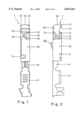
- FIG. 1 plan view of the bottom wall of a crimp connection of a contact spring according to the invention with a crimp connection and a detent sleeve fitted over it;
- FIG. 2 is an elevational view of the contact spring of FIG. 1, rotated to the right by 90° about its longitudinal axis;
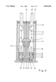
- FIG. 3 is a longitudinal sectional view through a surrounding housing with a sealing plate and contact chambers, into which two contact springs of FIGS. 1 and 2 are inserted.
- FIGS. 1 and 2 there is seen an exemplary embodiment of a contact spring according to the invention.
- the contact spring is identified by reference numeral 1 and has a base spring 10, Such a base spring 10 is described in detail for instance in the earlier German patent applications P 196 11 698.8 and P 195 13 582.2, which are herewith incorporated by reference.
- the base spring 10 has a connecting part 11 and a contact part 12.
- the connecting part in the exemplary embodiment of FIGS. 1 and 2, is embodied as a so-called crimp connection with an insulation claw and a conductor wire claw, to which an electrical power line can be connected.
- any other form of connecting part can also be chosen, such as a so-called IDC connector (insulation displacement connector) or the like.
- the contact part 12 of the base spring 10 is integrally connected to the connecting part 11.
- the base spring 10 On the end toward the insertion side, the base spring 10 has at least two spring arms 13, which are provided as introduction funnels for a pin contact to be introduced between the two spring arms 13.
- a boxlike detent sleeve 20 is clamped onto the base spring 10.
- the detent sleeve 20 is provided, on its side toward the insertion side, with two opposed guard tabs 23, which are bent inward at an angle of approximately 45°. These two guard tabs 23 may additionally be provided with an embossed feature. Located between these two guard tabs 23 are two further guard tabs 24, 25, which are each bent backward by 180° on their ends. The guard tab 24, with its bent-over end, extends approximately as far as the distal ends of the guard tabs 23. Conversely, the guard tab 25, with its wall portion bent over by 180°, is disposed with its front end set back.
- the detent sleeve 20 is formed with a void or a recess 22, which in the plan view of FIG. 1 has an approximately rectangular shape and in the exemplary embodiment shown extends over the entire broad side of the detent sleeve 20.
- the void 22 is located in the region of the detent sleeve 20 past which the spring arms 13 protrude in the direction of the insertion side of the contact spring 1. This void 22, together with detent elements of a surrounding housing, forms the primary securing means of the contact spring 1. This will be described in further detail below in conjunction with FIG. 3.
- the detent sleeve 20 moreover has a so-called force boosting tab 27.
- force boosting tab 27 pressure is additionally exerted on the spring arms 13 of the base spring 10, on which the detent sleeve 20 is mounted.
- the force boosting tab 27 is approximately triangular in shape and is surrounded by a cutout 28.
- the force boosting tab 27 is preferably itself provided with a rounded or embossed feature 29, to prevent canting of the detent sleeve 20 when it is introduced into a surrounding housing of a plug connector.
- the detent sleeve 20 has a polarizing tab 26, which is formed onto the inside of a side wall of the detent sleeve 20.
- This polarizing tab 26 is embodied without burrs both in the insertion direction and conversely to the insertion direction of the contact spring 1. This can be accomplished by using a suitable punch to push the force boosting tab 26 out of the sheet metal from which the detent sleeve 20 is stamped out.
- the polarizing tab 26 extends from the left side wall of the detent sleeve 20 upward by an angle of approximately 30 and then via a rounded bend extends back to the side wall forming approximately a right angle with it.
- FIG. 3 there is shown a surrounding housing 40 with two contact chambers 41, located side by side, into each of which there is inserted one of the contact springs 1 described above with reference to FIGS. 1 and 2.
- the two contact springs 1 are rotated by 180° relative to one another, with the two voids or recesses 22 pointing toward one another.
- One electrical power cord 30 is connected to each of the two contact springs 1.
- the electrical power cord 30 is clamped or soldered to the contact part 12 of the contact spring 1.
- the two contact springs 1 are properly inserted into the contact chambers 41 of the surrounding housing 40.
- the surrounding housing 40 is seated on a plate with contact pins 60, which are each inserted between the spring arms 13 of the base spring 10 and thus assure an electrical contact between the power cord 30 and the contact pins 60.
- the two contact chambers 41 are separated from one another by a center partition 42 and a slide element 43 that is known per se.
- the slide element 43 is T-shaped in cross section and with edges 44 engages the detent sleeves 20 from behind in such a way as to assure a secondary locking of the contact springs 1.
- this slide element 43 is inserted in a direction orthogonal to the insertion direction of the contact spring, into the surrounding housing 40, in a direction orthogonal to the insertion direction of the contact spring, as a securing element.
- the surrounding housing 40 has one wall part 45 assigned to each contact chamber 41, and this wall part is provided on its end with a detent hook 46, which can engage the void 22 of the contact spring 1.
- the wall part 45 is embodied resiliently inside the surrounding housing 40.
- the detent hook 46 on its end toward the insertion side, has an edge 47 extending orthogonally to the insertion direction and an oblique edge 48 extending remote from the insertion direction.
- the guard tab 24 presses the detent hook 46 backward by sliding along the oblique edge 48, and when the tip of the guard tab 25 strikes the face end of the contact chamber 41, this hook snaps resiliently into the void 22 of the detent sleeve 20.
- the resilient wall part 45 is integrally joined to the center partition 42.
- the surrounding housing 40 on its distal end from the insertion side, has a sealing plate 70, which for example may be a rubber plate.
- the sealing plate 70 serves to seal off the plug connector and it is preferably formed with holes whose cross section is smaller than the cross section of a contact spring 1.
- the contact springs 1 On insertion of the contact springs into the surrounding housing 40, the contact springs 1 have to be pushed through these openings of the sealing plate 70. Since the contact spring 1, according to the invention, has no sharp edges, the contact spring 1 can be inserted through the sealing plate 70, into the contact chambers 41, without injuring it. Even for repair purposes, the contact springs can be pulled back out of the contact chambers 41 without risk to the sealing plate 70.
Landscapes
- Connector Housings Or Holding Contact Members (AREA)
Applications Claiming Priority (2)
| Application Number | Priority Date | Filing Date | Title |
|---|---|---|---|
| DE19630939 | 1996-07-31 | ||
| DE19630939A DE19630939C1 (de) | 1996-07-31 | 1996-07-31 | Kontaktfeder |
Publications (1)
| Publication Number | Publication Date |
|---|---|
| US6033262A true US6033262A (en) | 2000-03-07 |
Family
ID=7801403
Family Applications (1)
| Application Number | Title | Priority Date | Filing Date |
|---|---|---|---|
| US08/904,000 Expired - Fee Related US6033262A (en) | 1996-07-31 | 1997-07-31 | Contact spring |
Country Status (6)
| Country | Link |
|---|---|
| US (1) | US6033262A (fr) |
| EP (1) | EP0822615B1 (fr) |
| JP (1) | JPH1069932A (fr) |
| KR (1) | KR980012720A (fr) |
| DE (2) | DE19630939C1 (fr) |
| ES (1) | ES2172715T3 (fr) |
Cited By (10)
| Publication number | Priority date | Publication date | Assignee | Title |
|---|---|---|---|---|
| EP1134848A1 (fr) * | 2000-03-15 | 2001-09-19 | Sumitomo Wiring Systems, Ltd. | Connecteur et ensemble de bornes de contact |
| US6338638B2 (en) * | 1998-11-12 | 2002-01-15 | Yazaki Corporation | Electric connector and terminal |
| US20030228798A1 (en) * | 2002-06-06 | 2003-12-11 | Sumitomo Wiring Systems, Ltd. | Terminal fitting and a connector provided therewith |
| US6746277B2 (en) | 2001-12-05 | 2004-06-08 | Tyco Electronics Corporation | Coaxial cable connector |
| US6746268B2 (en) | 2001-12-05 | 2004-06-08 | Tyco Electronics Corporation | Coaxial cable displacement contact |
| US20040142605A1 (en) * | 2002-11-05 | 2004-07-22 | Tomonori Harada | Female terminal and electric connector with the female terminals |
| WO2008115687A1 (fr) * | 2007-03-16 | 2008-09-25 | Lam Research Corporation | Connecteur électrique de grande puissance pour dispositif de chauffage en couches |
| US20140329401A1 (en) * | 2013-05-02 | 2014-11-06 | GM Global Technology Operations LLC | Electrical connector assembly for an electronic module |
| WO2019155468A1 (fr) | 2018-02-08 | 2019-08-15 | Yissum Research Development Company Of The Hebrew University Of Jerusalem Ltd. | Composés hétéroaryle, compositions pharmaceutiques de ceux-ci, et leur utilisation thérapeutique |
| WO2020247345A1 (fr) | 2019-06-03 | 2020-12-10 | Biotheryx, Inc. | Sels cristallins non hygroscopiques d'un composé pyrazole, compositions pharmaceutiques et utilisation de ceux-ci |
Families Citing this family (2)
| Publication number | Priority date | Publication date | Assignee | Title |
|---|---|---|---|---|
| DE19841216C2 (de) * | 1998-09-09 | 2001-02-15 | Framatome Connectors Int | Buchsenstecker für elektrische Verbinder mit Kodierrippe |
| WO2001006659A1 (fr) * | 1999-07-16 | 2001-01-25 | Koninklijke Philips Electronics N.V. | Conversion analogique-numerique |
Citations (11)
| Publication number | Priority date | Publication date | Assignee | Title |
|---|---|---|---|---|
| EP0070098A2 (fr) * | 1981-06-22 | 1983-01-19 | Trw Inc. | Coupleur hybride pour conducteurs optiques/électriques, coupleur pour fibres optique, crampon pour fibre optique et logement covenable |
| US5002504A (en) * | 1989-10-16 | 1991-03-26 | Labinal Components & Systems, Inc. | Electrical connector latch construction |
| DE4203379A1 (de) * | 1992-02-06 | 1993-08-12 | Daut & Rietz Trw | Federkontakt fuer elektrische flachstecksysteme |
| DE4227287A1 (de) * | 1992-08-18 | 1994-02-24 | Framatome Connectors Int | Elektrischer Federkontakt |
| FR2698730A1 (fr) * | 1992-11-30 | 1994-06-03 | Cinch Connecteurs Sa | Elément de boîtier de connecteur électrique et organe de contact électrique femelle destiné à être monté dans ledit élément de boîtier. |
| DE4312549A1 (de) * | 1993-04-17 | 1994-10-20 | Licentia Gmbh | Verfahren zur Drehmomentbegrenzung beim Sanftanlauf von Drehstromasynchronmotoren |
| DE19513582A1 (de) * | 1995-04-10 | 1996-10-24 | Siemens Ag | Kontaktfeder |
| US5607327A (en) * | 1993-12-06 | 1997-03-04 | Yazaki Corporation | Double locking connector |
| US5660555A (en) * | 1994-11-07 | 1997-08-26 | Sumitomo Wiring Systems, Ltd. | Waterproof connector and method for assembling the same |
| DE19611698A1 (de) * | 1996-03-25 | 1997-10-02 | Siemens Ag | Kontaktfeder |
| US5791945A (en) * | 1995-04-13 | 1998-08-11 | The Whitaker Corporation | High force contact |
Family Cites Families (4)
| Publication number | Priority date | Publication date | Assignee | Title |
|---|---|---|---|---|
| DE8810033U1 (de) * | 1988-08-05 | 1989-11-30 | TRW Daut + Rietz GmbH & Co KG, 8500 Nürnberg | Flachkontaktsteckhülse |
| DE9202365U1 (de) * | 1992-02-24 | 1993-06-17 | Siemens Ag, 8000 Muenchen | Kontaktfeder mit Rasthülse |
| DE4321549C2 (de) * | 1993-06-29 | 2000-03-30 | Framatome Connectors Int | Flachkontaktsteckhülse |
| JP5983826B2 (ja) * | 2015-06-23 | 2016-09-06 | 株式会社三洋物産 | 遊技機 |
-
1996
- 1996-07-31 DE DE19630939A patent/DE19630939C1/de not_active Expired - Fee Related
-
1997
- 1997-06-25 EP EP97110420A patent/EP0822615B1/fr not_active Expired - Lifetime
- 1997-06-25 DE DE59706832T patent/DE59706832D1/de not_active Expired - Fee Related
- 1997-06-25 ES ES97110420T patent/ES2172715T3/es not_active Expired - Lifetime
- 1997-07-28 JP JP9201615A patent/JPH1069932A/ja not_active Withdrawn
- 1997-07-30 KR KR1019970036087A patent/KR980012720A/ko not_active Application Discontinuation
- 1997-07-31 US US08/904,000 patent/US6033262A/en not_active Expired - Fee Related
Patent Citations (11)
| Publication number | Priority date | Publication date | Assignee | Title |
|---|---|---|---|---|
| EP0070098A2 (fr) * | 1981-06-22 | 1983-01-19 | Trw Inc. | Coupleur hybride pour conducteurs optiques/électriques, coupleur pour fibres optique, crampon pour fibre optique et logement covenable |
| US5002504A (en) * | 1989-10-16 | 1991-03-26 | Labinal Components & Systems, Inc. | Electrical connector latch construction |
| DE4203379A1 (de) * | 1992-02-06 | 1993-08-12 | Daut & Rietz Trw | Federkontakt fuer elektrische flachstecksysteme |
| DE4227287A1 (de) * | 1992-08-18 | 1994-02-24 | Framatome Connectors Int | Elektrischer Federkontakt |
| FR2698730A1 (fr) * | 1992-11-30 | 1994-06-03 | Cinch Connecteurs Sa | Elément de boîtier de connecteur électrique et organe de contact électrique femelle destiné à être monté dans ledit élément de boîtier. |
| DE4312549A1 (de) * | 1993-04-17 | 1994-10-20 | Licentia Gmbh | Verfahren zur Drehmomentbegrenzung beim Sanftanlauf von Drehstromasynchronmotoren |
| US5607327A (en) * | 1993-12-06 | 1997-03-04 | Yazaki Corporation | Double locking connector |
| US5660555A (en) * | 1994-11-07 | 1997-08-26 | Sumitomo Wiring Systems, Ltd. | Waterproof connector and method for assembling the same |
| DE19513582A1 (de) * | 1995-04-10 | 1996-10-24 | Siemens Ag | Kontaktfeder |
| US5791945A (en) * | 1995-04-13 | 1998-08-11 | The Whitaker Corporation | High force contact |
| DE19611698A1 (de) * | 1996-03-25 | 1997-10-02 | Siemens Ag | Kontaktfeder |
Non-Patent Citations (2)
| Title |
|---|
| German Utility Model G 88 10 033.2, dated Jan. 11, 1990. * |
| German Utility Model G 92 02 365.7, dated Jul. 29, 1993. * |
Cited By (16)
| Publication number | Priority date | Publication date | Assignee | Title |
|---|---|---|---|---|
| US6338638B2 (en) * | 1998-11-12 | 2002-01-15 | Yazaki Corporation | Electric connector and terminal |
| EP1134848A1 (fr) * | 2000-03-15 | 2001-09-19 | Sumitomo Wiring Systems, Ltd. | Connecteur et ensemble de bornes de contact |
| US6435921B2 (en) * | 2000-03-15 | 2002-08-20 | Sumitomo Wiring Systems, Ltd. | Connector and a set of terminal fittings |
| US6746277B2 (en) | 2001-12-05 | 2004-06-08 | Tyco Electronics Corporation | Coaxial cable connector |
| US6746268B2 (en) | 2001-12-05 | 2004-06-08 | Tyco Electronics Corporation | Coaxial cable displacement contact |
| US20030228798A1 (en) * | 2002-06-06 | 2003-12-11 | Sumitomo Wiring Systems, Ltd. | Terminal fitting and a connector provided therewith |
| US6729904B2 (en) * | 2002-06-06 | 2004-05-04 | Sumitomo Wiring Systems, Ltd. | Terminal fitting and a connector provided therewith |
| US6840824B2 (en) * | 2002-11-05 | 2005-01-11 | Yazaki Corporation | Female terminal and electric connector with the female terminals |
| US20040142605A1 (en) * | 2002-11-05 | 2004-07-22 | Tomonori Harada | Female terminal and electric connector with the female terminals |
| WO2008115687A1 (fr) * | 2007-03-16 | 2008-09-25 | Lam Research Corporation | Connecteur électrique de grande puissance pour dispositif de chauffage en couches |
| CN101636824B (zh) * | 2007-03-16 | 2011-12-14 | 朗姆研究公司 | 用于分层加热器的高功率电气接头 |
| TWI426561B (zh) * | 2007-03-16 | 2014-02-11 | Lam Res Corp | 疊層加熱器用之高功率電連接器 |
| US20140329401A1 (en) * | 2013-05-02 | 2014-11-06 | GM Global Technology Operations LLC | Electrical connector assembly for an electronic module |
| US9325108B2 (en) * | 2013-05-02 | 2016-04-26 | GM Global Technology Operations LLC | Electrical connector assembly for an electronic module |
| WO2019155468A1 (fr) | 2018-02-08 | 2019-08-15 | Yissum Research Development Company Of The Hebrew University Of Jerusalem Ltd. | Composés hétéroaryle, compositions pharmaceutiques de ceux-ci, et leur utilisation thérapeutique |
| WO2020247345A1 (fr) | 2019-06-03 | 2020-12-10 | Biotheryx, Inc. | Sels cristallins non hygroscopiques d'un composé pyrazole, compositions pharmaceutiques et utilisation de ceux-ci |
Also Published As
| Publication number | Publication date |
|---|---|
| DE59706832D1 (de) | 2002-05-08 |
| DE19630939C1 (de) | 1997-12-11 |
| ES2172715T3 (es) | 2002-10-01 |
| EP0822615B1 (fr) | 2002-04-03 |
| EP0822615A3 (fr) | 1999-01-27 |
| KR980012720A (ko) | 1998-04-30 |
| EP0822615A2 (fr) | 1998-02-04 |
| JPH1069932A (ja) | 1998-03-10 |
Similar Documents
| Publication | Publication Date | Title |
|---|---|---|
| US5695368A (en) | Electrical terminal with protected locking lance and a connector therefor | |
| EP0877390B1 (fr) | Borne électrique femelle | |
| JP4650918B2 (ja) | 電気コネクタ | |
| KR100264848B1 (ko) | 소켓형 콘택트 및 이를 이용하는 전기커넥터 | |
| EP1469561A2 (fr) | Terminal | |
| US5899775A (en) | Contact with retention lance and housing therefor | |
| JP2001332352A (ja) | 慣性ロック式コネクタ | |
| US6033262A (en) | Contact spring | |
| US5160279A (en) | Double lock connector | |
| US6354867B1 (en) | Female electrical connector | |
| JPH05275135A (ja) | 雌型電気端子 | |
| US6290554B1 (en) | Female terminal fitting and a female connector | |
| KR20050044303A (ko) | 암형 단자 피팅 | |
| US5716232A (en) | Female terminal for connector | |
| EP1134848B1 (fr) | Connecteur et ensemble de bornes de contact | |
| US3373398A (en) | Terminal block | |
| JP3717057B2 (ja) | コネクタのサイドスペーサ構造 | |
| US6533602B2 (en) | Divided connector | |
| JPH11191443A (ja) | 圧接コネクタ | |
| US5314358A (en) | Terminal position assurance system for electrical connectors | |
| US6669508B2 (en) | Connector | |
| US5358416A (en) | Electric connector | |
| US20240136768A1 (en) | Connector mating structure | |
| JPH081568Y2 (ja) | 電気コネクタ | |
| JP2801774B2 (ja) | 固定手段を有するレセプタクル端子 |
Legal Events
| Date | Code | Title | Description |
|---|---|---|---|
| AS | Assignment |
Owner name: SIEMENS AKTIENGESELLSCHAFT, GERMANY Free format text: ASSIGNMENT OF ASSIGNORS INTEREST;ASSIGNORS:HEIMUELLER, HANS-JOST;STRAEB, MARTIN;REEL/FRAME:010578/0702;SIGNING DATES FROM 19970811 TO 19970814 |
|
| AS | Assignment |
Owner name: TYCO ELECTRONICS LOGISTICS AG, SWITZERLAND Free format text: ASSIGNMENT OF ASSIGNORS INTEREST;ASSIGNOR:SIEMENS AKTIENGESELLSCHAFT;REEL/FRAME:012025/0862 Effective date: 20001211 |
|
| FPAY | Fee payment |
Year of fee payment: 4 |
|
| REMI | Maintenance fee reminder mailed | ||
| LAPS | Lapse for failure to pay maintenance fees | ||
| STCH | Information on status: patent discontinuation |
Free format text: PATENT EXPIRED DUE TO NONPAYMENT OF MAINTENANCE FEES UNDER 37 CFR 1.362 |
|
| FP | Lapsed due to failure to pay maintenance fee |
Effective date: 20080307 |