US5960922A - Hydraulic cylinder such as a clutch master or servant cylinder in a motor vehicle having a bleed element - Google Patents
Hydraulic cylinder such as a clutch master or servant cylinder in a motor vehicle having a bleed element Download PDFInfo
- Publication number
- US5960922A US5960922A US08/859,151 US85915197A US5960922A US 5960922 A US5960922 A US 5960922A US 85915197 A US85915197 A US 85915197A US 5960922 A US5960922 A US 5960922A
- Authority
- US
- United States
- Prior art keywords
- aperture
- bleeding
- cylinder
- disposed
- shoulder
- Prior art date
- Legal status (The legal status is an assumption and is not a legal conclusion. Google has not performed a legal analysis and makes no representation as to the accuracy of the status listed.)
- Expired - Fee Related
Links
Images


Classifications
-
- F—MECHANICAL ENGINEERING; LIGHTING; HEATING; WEAPONS; BLASTING
- F15—FLUID-PRESSURE ACTUATORS; HYDRAULICS OR PNEUMATICS IN GENERAL
- F15B—SYSTEMS ACTING BY MEANS OF FLUIDS IN GENERAL; FLUID-PRESSURE ACTUATORS, e.g. SERVOMOTORS; DETAILS OF FLUID-PRESSURE SYSTEMS, NOT OTHERWISE PROVIDED FOR
- F15B21/00—Common features of fluid actuator systems; Fluid-pressure actuator systems or details thereof, not covered by any other group of this subclass
- F15B21/04—Special measures taken in connection with the properties of the fluid
- F15B21/044—Removal or measurement of undissolved gas, e.g. de-aeration, venting or bleeding
-
- F—MECHANICAL ENGINEERING; LIGHTING; HEATING; WEAPONS; BLASTING
- F16—ENGINEERING ELEMENTS AND UNITS; GENERAL MEASURES FOR PRODUCING AND MAINTAINING EFFECTIVE FUNCTIONING OF MACHINES OR INSTALLATIONS; THERMAL INSULATION IN GENERAL
- F16D—COUPLINGS FOR TRANSMITTING ROTATION; CLUTCHES; BRAKES
- F16D2125/00—Components of actuators
- F16D2125/02—Fluid-pressure mechanisms
- F16D2125/16—Devices for bleeding or filling
Definitions
- the present invention relates to a cylinder for pressure media, in particular a hydraulic master or slave cylinder in motor vehicles, having a bleed element screwed into an aperture in the cylinder casing, which bleed element is sealed against the casing.
- the plenum is sealed by means of a screw-type bleed element which is screwed into a threaded aperture in the cylinder casing.
- bleed elements typically have conical sealing faces, which sealing faces are brought into contact with corresponding seal seats by the application of an axial force.
- the advantage of the conical seal seat is that only a few rotations are required to open the bleed element, making bleeding very easy.
- Laid-Open German Patent Application DE-OS 195 16 389.3 teaches the use of a radial sealing ring. However, a greater number of rotations is required to open the bleed element with this solution than is the case with the conical seal seat.
- a cylinder for pressure media having a bleed element which bleed element is designed such that a lasting and trouble-free seal is obtained while retaining easy bleeding offered by a conical seal.
- the current invention teaches the use of a generic cylinder for pressure media characterized by the fact that the bleed element can be functionally connected at the casing end to a round sealing element which can be pressed axially against a shoulder located in the aperture.
- the sealing element can preferably be formed by an elastic cap fastened to a journal or pin or stud of the bleed element, which cap can be braced against a bead on the floor of the aperture.
- the sealing element can be inserted into the aperture and braced against a bead on the shoulder of the aperture by means of a journal mounted on one end of the bleed element.
- the advantage of the elastic cap mounted to the bleed element compared to an insertable sealing element is that it cannot be lost if the bleed element is separated from the cylinder. Furthermore, preassembled units can be made available.
- the bead is preferably ring-shaped and can be directly adjacent to the opening of the connecting aperture to the plenum of the cylinder. This configuration can ensure that the sealing element rests firmly against the floor of the aperture over the entire circumference of the connecting aperture.
- the sealing element is ring-shaped.
- the sealing element can be realized as an O-ring seated in a groove in the bleed element, for example.
- the advantage of the ring shape is that the pressure inside the cylinder does not weaken the seal but exerts a radial force against the inside of the sealing element, thus enhancing the seal by increasing the force with which the sealing element is pressed against the sealing surface.
- An increase in internal pressure also further expands the ring-shaped sealing element, causing it to expand radially toward the aperture in the casing.
- the end of the bleed element which is inserted into the casing transitions into a centering journal which engages in a narrowing section of the aperture. This can ensure that the bleed element is properly positioned when screwed into the casing.
- the journal also protects against the loss of the sealing element and offers the advantage that preassembled units can be made available.
- the cylinder can be bled even when pressurized internally.
- the cylinder can be vented by two people, one of whom presses the clutch pedal while the other removes the bleed screw. Because the internal pressure can deform the sealing element, the pressure is relieved via the bleed duct.
- the aperture at the height of the sealing element has at least one axial groove extending above the height of the sealing element.
- a plurality of grooves distributed over the circumference of the aperture is preferable.
- the bleed element To limit the depth to which the bleed element can be screwed in and thus to protect the axial seal against overloading, it is advantageous for the bleed element to be equipped with a radially protruding shoulder, which makes contact with the outside of the cylinder casing.
- a variant can be realized by means of a shoulder located behind the internal thread in the aperture (at the run-out of the thread) and extending radially inward, with which shoulder a surface or widened area of the bleed element makes contact.
- a radial seal to prevent fluid from leaking between the sealing element and the thread of the bleed element is particularly advantageous.
- Another advantageous seal to prevent fluid from leaking can be realized if there are two diametrical ribs which protrude radially outward and run the length of the external thread of the bleed element.
- the mold seam can be widened slightly so that material can accumulate there during injection molding.
- the ribs are squeezed such that the thread is sealed. In this embodiment, it can initially be somewhat more difficult to screw in the bleed element.
- invention includes “inventions”, that is, the plural of "invention”.
- invention the Applicants do not in any way admit that the present application does not include more than one patentably and non-obviously distinct invention, and maintains that this application may include more than one patentably and non-obviously distinct invention.
- disclosure of this application may include more than one invention, and, in the event that there is more than one invention, that these inventions may be patentable and non-obvious one with respect to the other.
- FIGS. 1A and 1B each show examples of hydraulically operated clutch assemblies
- FIG. 1 shows a bleed element screwed into a cylinder for pressure media
- FIG. 1C shows FIG. 1 in more detail
- FIG. 2 shows another embodiment of a bleed element screwed into a cylinder for pressure media
- FIG. 2A shows FIG. 2 in more detail
- FIG. 3 shows an embodiment of the bleed element shown in FIG. 1;
- FIG. 3A shows FIG. 3 in more detail
- FIG. 4 shows an embodiment of a cylinder for pressure media in which the thread between the bleed element and casing is sealed
- FIG. 4A shows a partial view of the bleed element thread
- FIG. 4B shows an enlarged partial plan view of the bleed element
- FIG. 4C shows a section along the line A--A in FIG. 4;
- FIG. 4D shows FIG. 4 in more detail
- FIG. 5 shows another embodiment of a bleed element screwed into a cylinder for pressure media, with the bleed element in the closed position
- FIG. 5A shows FIG. 5 in more detail
- FIG. 6 shows the cylinder from FIG. 5 with the bleed element open
- FIG. 6A shows FIG. 6 in more detail
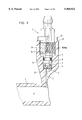
- FIG. 7 shows a variant of the embodiment shown in FIG. 5;
- FIG. 7A shows FIG. 7 in more detail
- FIG. 8 shows another embodiment of a bleed element screwed into a cylinder for pressure media
- FIG. 8A shows FIG. 8 in more detail
- FIG. 9 shows a section through the cylinder at the height of the bleed element
- FIG. 10 shows the section shown in FIG. 9 for another embodiment of a cylinder for pressure media.
- FIG. 1A essentially shows a view of one possible use of a cylinder 103 described herein.
- the cylinder 103 in accordance with the present invention, could be used as a master or a servant cylinder in a hydraulic clutch system. As shown in FIG. 1A, the cylinder 103 is used as a servant cylinder.
- Such a system can preferably have a remote fluid reservoir 46 and a clutch master cylinder 47, the two being connected to one another by means of a line 59.
- the clutch master cylinder 47 can preferably be mounted opposite the dash of a motor vehicle, i.e.
- the clutch pedal of the vehicle preferably be means of a push rod 51, the clutch pedal being shown schematically in FIG. 1A.
- the master cylinder 47 can also have a protective boot 52.
- the cylinder or servant cylinder 103 can preferably be mounted by means of a fastening connection (not shown in FIG. 1A) on a clutch housing 55 (see FIG. 1B).
- a connecting element 40 can preferably be attached to a clutch release fork or throwout lever 51 (see FIG. 1B).
- the clutch master cylinder 47 in accordance with the embodiment shown in FIG. 1A, preferably operates as the pump for pumping hydraulic fluid from reservoir 46, via a connection 48 and cylinder 49, to the servant cylinder 103.
- hydraulic fluid under pressure can be pumped into the servant cylinder 103, via a line 50, and can cause a piston rod (not shown) to extend.
- the outer end of the piston rod can cause the clutch release fork 51 to pivot and force a clutch release bearing 58 (see FIG. 1B) to disengage the clutch. Since hydraulic systems are generally self-adjusting, when the clutch pedal is released, hydraulic pressure can fall off, and the piston rod of the servant cylinder 103 can withdraw.
- the cylinder 103 could also be used as the master cylinder in the hydraulic clutch system shown in FIG. 1A.
- the piston rod can preferably be operatively attached to the clutch pedal by means of push rod 51, hydraulic fluid can be received from reservoir 46, and a connection 62 can be used to provide hydraulic fluid, via line 50, to the servant cylinder.
- FIG. 1B shows a more complete hydraulic clutch system including a flywheel 60, a clutch disc 61, a clutch cover 53 having a movable pressure plate 54 disposed therein, and a clutch housing 55.
- the clutch system can also include a throwout or release bearing 58 and a clutch release fork or throwout lever 57, which release fork 57 can preferably be operatively attached to the servant cylinder 103.
- the servant cylinder 103 can preferably be connected, via line 50, to the master cylinder 47, the actual connection of which is not shown here for purposes of simplicity.
- the master cylinder 47 can preferably be connected to the clutch pedal 56, and to the reservoir 46 by means of line 59.
- FIG. 1 shows a partial longitudinal section of a cylinder for pressure media into which a bleed element 4 has been screwed.
- the cylinder includes a plenum 2 in which a piston (not shown) has been installed such that it can be moved axially and by means of which piston the pressure can be relieved.
- the plenum 2 is connected to the seat of the bleed element 4 via the access aperture 3.
- the bleed element 4 is screwed into a stepped aperture 9 in the casing 1 via a thread 10, 10a.
- the shank 8 of the bleed element 4 is equipped on that side facing the plenum 2 with a journal 7, onto which a cap 5 of some elastic material is snapped.
- the journal 7 is equipped with a circumferential groove 100 (see FIG. 1C) in which the bottom of the cap 5 engages.
- Located at the base of the aperture 9 is a circumferential bead 6 which limits the edge of the opening to the access aperture 3 and against which bead 6 the cap 5 is braced in the axial direction.
- the bleed element 4 has a shoulder 12 which protrudes outward and makes contact with the outside of the casing 1 at the point marked 11.
- a radial seal 13 installed in a circumferential groove 101 (see FIG. 1C) in the shank 8. This radial seal 13 is preferably an O-ring.
- a bleed duct 15 of the bleed element 4 is aligned with a center line 14. This bleed duct 15 remains closed as long as the sealing cap 5 is tight. If the bleed element 4 is screwed out of the aperture 9, the sealing cap 5 loses its seal and a connection between the access aperture 3 and the bleed duct 15 is established. In this case, the radial seal 13 prevents the pressure medium from escaping through the thread 10, 10a.
- the bleed duct 15 can (although not shown here) have a polygonal, e.g. rectangular or hexagonal, cross-section which can easily be engaged by a corresponding wrench for removal of the bleed element 4 from the casing 1.
- FIG. 1C shows the flow pathway that can be established when the sealing cap 5 loses its seal with the access aperture 3 and the connection between the bleed duct 15 and the access aperture 3 is established.
- the pressure medium may travel from the access aperture 3 through the pathway between the sealing cap 5 and the stepped aperture 9. The pressure medium may then flow from this pathway into an opening passage 102 in the bleed duct 15.
- shoulder 19 is positioned to that it can support the cap 5.
- the sealing element is a sealing disk 5' which is inserted loosely into the aperture 9.
- a bead 6 against which the sealing disk 5' is braced encircles the opening of the access aperture 3 in the casing 1.
- the outside diameter of the sealing disk 5' is smaller than the inside diameter of the aperture 9.
- the end shank 8 is equipped with a planar journal 7', which has a greater outside diameter than the sealing disk 5'.
- FIG. 2A shows the flow pathway between the access aperture 3 and the bleed duct 15 in which the bleed duct 15 has a rectangular opening 26 which permits fluid to enter the bleed duct 15.
- FIG. 3 shows a variant of the embodiment shown in FIG. 1.
- a shoulder protruding radially inward and which makes contact with a limit stop 16 on the bleed element 4 between the end shank 8 and the thread 10 is located behind the internal thread 10a in the aperture 9.
- FIG. 3A shows the flow pathway between the access aperture 3 and the bleed duct 15 in which the bleed duct 15 has a circular opening 27 which permits fluid to enter the bleed duct 15.
- FIGS. 4a, 4b, and 4c show another embodiment of the bleed element in which there are two ribs 17, 18 extending radially over the threads 10, 10' to prevent leakage losses at the thread 10 of the bleed element 4.
- These diametrically opposed ribs 17, 18 are created during injection molding of the bleed element 4 by widening the mold seam so that material can accumulate there.
- the ribs 17, 18 protrude axially over the full length of the thread 10. It can be advantageous if the ribs 17, 18 extend over a complete turn 10' of the thread 10 in the lower region.
- FIGS. 4D, 5, 5A, 6, 6A, 7, 7A, 8 and 8A show additional embodiments of the flow pathway between the access aperture 3 and the bleed duct 15 in which the bleed duct 15 has a rectangular opening 26.
- FIGS. 5, 5A, 6, 6A, 7, 7A, 8 and 8A show additional embodiments of a cylinder for pressure media in which an axial seal is formed by means of an O-ring 20, 20' located at one end of the bleed element 4.
- the O-ring 20 lies in a groove 21 in the bleed element 4.
- the bleed element 4 transitions into a journal 22 whose outside diameter is less than the outside diameter at the other side of the groove 21.
- This journal 22 centers the bleed element in a narrowing section 9a of the stepped or graduated aperture 9.
- FIGS. 5A and 6A also show a rectangular opening 26 to allow a flow path through the cylinder.
- FIG. 6 illustrates the withdrawn position, where the shoulder 12 no longer makes contact with the contact point 11. Also a bleed duct 23 is now open by the withdrawal of the bleed element 4.
- FIGS. 7 and 7A illustrate an embodiment of the bleed element 4 which, similar to the one in FIG. 3, does not have an external shoulder to seat on the casing 1. Instead, a stop 16 is provided at the end of the threads 10, 10' which internally seat the bleed element 4 against the casing 1.
- the O-ring 20' is loosely connected to the bleed element 4.
- the inner diameter of the O-ring 20' fits around a correspondingly shaped tapered section 4a on one end of the seal element 4. Function is otherwise identical to that of the embodiment described above.
- the advantage of the loosely mounted O-ring 20' is that manufacturing costs are low compared to the grooved design.
- the disadvantage is that, under certain usage conditions, it may not be certain that the O-ring 20' has been removed from the cylinder 1 and has not been inadvertently left on the shoulder 19.
- the aperture 9 is as shown in FIGS. 9 and 10 equipped with one or more bleed ducts 23, 25 in the vicinity of the seat for the O-ring 20, 20'.
- the bleed duct 23 shown in FIG. 9 is helical, with its mouth 23' located at the shoulder 19. A brief lifting of the O-ring 20 from its seat on the shoulder 19 permits bleeding via the bleed duct 23 even if the O-ring 20 is pressurized from within.
- FIG. 10 shows that one or more grooves 25 distributed over the circumference of the aperture 9 can also serve as bleed ducts.
- One feature of the invention resides broadly in the cylinder for pressure media, in particular a hydraulic master or servant cylinder in motor vehicles, having a bleed element 4 which can be screwed into an aperture 9 in the cylinder casing 1 and which is sealed against the casing 1, characterized by the fact that the bleed element 4 is functionally connected in the vicinity of that end inserted in the casing to a round sealing element 5, 5'; 20, 20', which is pressed axially against a shoulder 19 in the aperture 9.
- Another feature of the invention resides broadly in the cylinder for pressure media characterized by the fact that the sealing element 5, 5' has a planar sealing surface and is located on the face between the bleed element 4 and the casing 1.
- sealing element is realized as an elastic cap 5 mounted on the end of a journal or a pin or a stud 7 of the bleed element 4, which cap can be braced against a bead 6 on the floor of the aperture 9.
- Still another feature of the invention resides broadly in the cylinder for pressure media characterized by the fact that the sealing element 3 can be inserted in the aperture 9 and braced against a bead 6 on the floor of the aperture 9 and a planar journal 7 on the face of the bleed element 4.
- a further feature of the invention resides broadly in the cylinder for pressure media characterized by the fact that the bead 6 is ring-shaped.
- Another feature of the invention resides broadly in the cylinder for pressure media characterized by the fact that the bead is immediately adjacent to the opening of the access aperture 3 to the plenum 2.
- Yet another feature of the invention resides broadly in the cylinder for pressure media characterized by the fact that the sealing element 20, 20' is ring-shaped.
- Still another feature of the invention resides broadly in the cylinder for pressure media characterized by the fact that the sealing element is an O-ring 20 seated in a groove 21.
- a further feature of the invention resides broadly in the cylinder for pressure media characterized by the fact that the end of the bleed element 4 inserted into the casing transitions into a journal 22 which engages in a narrowing section 9a of the aperture to center the bleed element.
- Another feature of the invention resides broadly in the cylinder for pressure media characterized by the fact that the aperture 9 is equipped with a radial, helical bleed duct 23 at the height of the sealing element 20, 20', the mouth of which bleed duct ends at the shoulder 19.
- Yet another feature of the invention resides broadly in the cylinder for pressure media characterized by the fact that the aperture 9 has at least one axial groove 25 at the height of the sealing element 20, 20'.
- Still another feature of the invention resides broadly in the cylinder for pressure media characterized by the fact that there is a plurality of grooves 25 distributed around the circumference.
- a further feature of the invention resides broadly in the cylinder for pressure media characterized by the fact that the depth to which the bleed element 4 can be screwed in is limited by means of a radially protruding shoulder 12 which makes contact with the outside of the casing 1.
- Another feature of the invention resides broadly in the cylinder for pressure media characterized by the fact that the depth to which the bleed element 4 can be screwed in is limited by means of a shoulder located behind the thread 10a in the aperture 9 of the thread and extending radially inward, with which shoulder a surface 16 of the bleed element 4 makes contact.
- Yet another feature of the invention resides broadly in the cylinder for pressure media characterized by the fact that there is a radial seal 13 to prevent fluid from leaking between the sealing element 5, 5'; 20, 20' and the thread 10 of the bleed element 4.
- Still another feature of the invention resides broadly in the cylinder for pressure media characterized by the fact that there are two diametrical ribs 17, 18 which protrude radially outward over the threads and run the entire length of the external thread 10 of the bleed element 4.
- a further feature of the invention resides broadly in the cylinder for pressure media characterized by the fact that the ribs 17, 18 protrude axially over a complete turn 10'.
Landscapes
- Engineering & Computer Science (AREA)
- Chemical & Material Sciences (AREA)
- Analytical Chemistry (AREA)
- Physics & Mathematics (AREA)
- Fluid Mechanics (AREA)
- Mechanical Engineering (AREA)
- General Engineering & Computer Science (AREA)
- Hydraulic Clutches, Magnetic Clutches, Fluid Clutches, And Fluid Joints (AREA)
- Gasket Seals (AREA)
- Transmission Of Braking Force In Braking Systems (AREA)
Applications Claiming Priority (4)
| Application Number | Priority Date | Filing Date | Title |
|---|---|---|---|
| DE19620188 | 1996-05-20 | ||
| DE19620188 | 1996-05-20 | ||
| DE19648683 | 1996-11-25 | ||
| DE19648683A DE19648683C2 (de) | 1996-05-20 | 1996-11-25 | Druckmittelzylinder mit einem Entlüftungselement mit axialer Elastomerdichtung |
Publications (1)
| Publication Number | Publication Date |
|---|---|
| US5960922A true US5960922A (en) | 1999-10-05 |
Family
ID=26025839
Family Applications (1)
| Application Number | Title | Priority Date | Filing Date |
|---|---|---|---|
| US08/859,151 Expired - Fee Related US5960922A (en) | 1996-05-20 | 1997-05-20 | Hydraulic cylinder such as a clutch master or servant cylinder in a motor vehicle having a bleed element |
Country Status (3)
| Country | Link |
|---|---|
| US (1) | US5960922A (es) |
| EP (1) | EP0809033B1 (es) |
| ES (1) | ES2197961T3 (es) |
Cited By (10)
| Publication number | Priority date | Publication date | Assignee | Title |
|---|---|---|---|---|
| US20040173644A1 (en) * | 2000-06-15 | 2004-09-09 | Christopher Ramsey | Fitment assembly for containers |
| US20050262840A1 (en) * | 2004-05-27 | 2005-12-01 | Zf Friedrichshafen Ag | Hydraulic actuation apparatus for a motor vehicle clutch |
| US20060207656A1 (en) * | 2005-03-15 | 2006-09-21 | Akihiko Takahashi | Air bleeding pipe joint |
| US20070034475A1 (en) * | 2005-08-11 | 2007-02-15 | Capito Russell T | Electronically-controlled hydraulically-actuated coupling |
| US20080214355A1 (en) * | 2005-08-11 | 2008-09-04 | American Axle & Manufacturing, Inc. | Electrohydraulic Torque Transfer Device |
| US20090212249A1 (en) * | 2005-06-20 | 2009-08-27 | Martin Maszull | Bleeding Screw Having a Kick-Back Valve |
| US20100243397A1 (en) * | 2005-08-11 | 2010-09-30 | Capito Russell T | Electronically-controlled hydraulically-actuated coupling |
| US8197386B2 (en) | 2005-08-11 | 2012-06-12 | American Axle & Manufacturing, Inc. | Electrohydraulic torque transfer device and temperature control system |
| US20180106312A1 (en) * | 2016-10-17 | 2018-04-19 | Campagnolo S.R.L. | Bleeding valve, a hydraulic fitting and a venting assembly for a bicycle hydraulic braking system |
| US10682997B2 (en) * | 2016-01-25 | 2020-06-16 | Liberty Vehicle Technologies Limited | Bleeding device and method of bleeding a hydraulic system |
Citations (19)
| Publication number | Priority date | Publication date | Assignee | Title |
|---|---|---|---|---|
| DE5575C (de) * | A. DOERING, Maschinenfabrikant, in Sinn, Reg. Bez. Wiesbaden | Neuerungen in der Befestigungsweise der Ventildichtungen aus Gummi | ||
| US2531705A (en) * | 1947-03-12 | 1950-11-28 | Bendix Aviat Corp | Master and receiver cylinder construction |
| US3098508A (en) * | 1959-05-08 | 1963-07-23 | Gerdes Claus-Holmer | Mixing valve |
| US3279743A (en) * | 1963-12-27 | 1966-10-18 | Garza Jesus De La | Non-drip faucet valve |
| US3406519A (en) * | 1965-04-08 | 1968-10-22 | Hackett Norman Henry | Booster unit for vehicle hydraulic brake systems |
| US3425750A (en) * | 1968-02-21 | 1969-02-04 | Hydrasearch Co Inc | Bleed apparatus for bleeding the brakes of a hybrid hydraulic brake system |
| US3491783A (en) * | 1967-09-11 | 1970-01-27 | Accessory Products Co | Discharge valve |
| US4181370A (en) * | 1978-02-21 | 1980-01-01 | Toyota Jidosha Kogyo Kabushiki Kaisha | Fluid pressure control device for vehicle braking systems |
| US4318460A (en) * | 1979-11-29 | 1982-03-09 | The Bendix Corporation | Pressurized fluid chamber with supply and bleed fitting |
| FR2538765A1 (fr) * | 1982-12-30 | 1984-07-06 | Peugeot | Dispositif hydraulique pour la commande du freinage ou de l'embrayage d'un vehicule automobile |
| US4470577A (en) * | 1982-03-26 | 1984-09-11 | General Motors Corporation | Corrosion resistant bleeder screw arrangement |
| US4840081A (en) * | 1987-02-18 | 1989-06-20 | Shimano Industrial Company Limited | Speed-change operating lever for a bicycle |
| US4909094A (en) * | 1986-12-24 | 1990-03-20 | Yoshigai Kikai Kinzoku Kabushiki Kaisha | Brake lever device for bicycles |
| US5009299A (en) * | 1989-03-08 | 1991-04-23 | Ina Walzlager Schaeffler Kg | Clutch actuating device |
| US5273141A (en) * | 1990-12-20 | 1993-12-28 | Bendix Europe Services Techniques | Bleed valve for a hydraulic circuit and process for bleeding a hydraulic circuit equipped with such a valve |
| US5448927A (en) * | 1994-05-03 | 1995-09-12 | Avid Enterprises, Inc. | Adjustable leverage brake lever |
| US5560457A (en) * | 1995-03-07 | 1996-10-01 | Dayton Walther Corporation | Bleeder screw for disc brake assembly |
| DE19516389A1 (de) * | 1995-05-04 | 1996-11-14 | Fichtel & Sachs Ag | Entlüftungselement |
| US5575178A (en) * | 1995-08-22 | 1996-11-19 | Wu; Chin-Chang | Brake handle |
Family Cites Families (10)
| Publication number | Priority date | Publication date | Assignee | Title |
|---|---|---|---|---|
| US2672999A (en) * | 1952-01-02 | 1954-03-23 | Protasoff George | Bottle stopper |
| US2941541A (en) * | 1956-10-18 | 1960-06-21 | Renault | Resilient packing rings for fluids under pressure |
| DE1425731B1 (de) * | 1963-07-10 | 1971-07-29 | Zahnradfabrik Friedrichshafen | Einrichtung zum entl]ften von druckmittelkreisl[ufen |
| US3561475A (en) * | 1966-04-05 | 1971-02-09 | Edward A Rockwell | Dual hydraulic brake systems and brake booster mechanisms therefor |
| DE1655411B2 (de) * | 1967-05-31 | 1974-01-03 | Alfred Teves Gmbh, 6000 Frankfurt | Entlüftungseinrichtung für hydraulische Zweikreisbremsanlagen für Fahrzeuge, insbesondere Kraftfahrzeuge |
| DE1956296A1 (de) * | 1969-11-08 | 1972-01-27 | Opel Adam Ag | Bremssattel fuer eine als Zweikreisbremse wirkende Scheibenbremse,insbesondere fuer Kraftfahrzeuge |
| JPS5646172A (en) * | 1979-09-20 | 1981-04-27 | Kubota Ltd | Vent valve |
| DE3341675C1 (de) * | 1983-11-18 | 1985-01-10 | Filterwerk Mann & Hummel Gmbh, 7140 Ludwigsburg | Sicherheitsverschluss fuer zweiteilige Gehaeuse zum Filtern von Fluessigkeiten |
| US5154452A (en) * | 1991-09-18 | 1992-10-13 | Frederick William Johnson | Tubular connection with S-thread form for clamping center seal |
| EP0647810A1 (de) * | 1993-07-30 | 1995-04-12 | Anton Hummel Verwaltungs GmbH | Schraubteil mit Dichtung zur Herstellung einer dichten Gewindeverbindung |
-
1997
- 1997-03-27 EP EP97105232A patent/EP0809033B1/de not_active Expired - Lifetime
- 1997-03-27 ES ES97105232T patent/ES2197961T3/es not_active Expired - Lifetime
- 1997-05-20 US US08/859,151 patent/US5960922A/en not_active Expired - Fee Related
Patent Citations (19)
| Publication number | Priority date | Publication date | Assignee | Title |
|---|---|---|---|---|
| DE5575C (de) * | A. DOERING, Maschinenfabrikant, in Sinn, Reg. Bez. Wiesbaden | Neuerungen in der Befestigungsweise der Ventildichtungen aus Gummi | ||
| US2531705A (en) * | 1947-03-12 | 1950-11-28 | Bendix Aviat Corp | Master and receiver cylinder construction |
| US3098508A (en) * | 1959-05-08 | 1963-07-23 | Gerdes Claus-Holmer | Mixing valve |
| US3279743A (en) * | 1963-12-27 | 1966-10-18 | Garza Jesus De La | Non-drip faucet valve |
| US3406519A (en) * | 1965-04-08 | 1968-10-22 | Hackett Norman Henry | Booster unit for vehicle hydraulic brake systems |
| US3491783A (en) * | 1967-09-11 | 1970-01-27 | Accessory Products Co | Discharge valve |
| US3425750A (en) * | 1968-02-21 | 1969-02-04 | Hydrasearch Co Inc | Bleed apparatus for bleeding the brakes of a hybrid hydraulic brake system |
| US4181370A (en) * | 1978-02-21 | 1980-01-01 | Toyota Jidosha Kogyo Kabushiki Kaisha | Fluid pressure control device for vehicle braking systems |
| US4318460A (en) * | 1979-11-29 | 1982-03-09 | The Bendix Corporation | Pressurized fluid chamber with supply and bleed fitting |
| US4470577A (en) * | 1982-03-26 | 1984-09-11 | General Motors Corporation | Corrosion resistant bleeder screw arrangement |
| FR2538765A1 (fr) * | 1982-12-30 | 1984-07-06 | Peugeot | Dispositif hydraulique pour la commande du freinage ou de l'embrayage d'un vehicule automobile |
| US4909094A (en) * | 1986-12-24 | 1990-03-20 | Yoshigai Kikai Kinzoku Kabushiki Kaisha | Brake lever device for bicycles |
| US4840081A (en) * | 1987-02-18 | 1989-06-20 | Shimano Industrial Company Limited | Speed-change operating lever for a bicycle |
| US5009299A (en) * | 1989-03-08 | 1991-04-23 | Ina Walzlager Schaeffler Kg | Clutch actuating device |
| US5273141A (en) * | 1990-12-20 | 1993-12-28 | Bendix Europe Services Techniques | Bleed valve for a hydraulic circuit and process for bleeding a hydraulic circuit equipped with such a valve |
| US5448927A (en) * | 1994-05-03 | 1995-09-12 | Avid Enterprises, Inc. | Adjustable leverage brake lever |
| US5560457A (en) * | 1995-03-07 | 1996-10-01 | Dayton Walther Corporation | Bleeder screw for disc brake assembly |
| DE19516389A1 (de) * | 1995-05-04 | 1996-11-14 | Fichtel & Sachs Ag | Entlüftungselement |
| US5575178A (en) * | 1995-08-22 | 1996-11-19 | Wu; Chin-Chang | Brake handle |
Cited By (17)
| Publication number | Priority date | Publication date | Assignee | Title |
|---|---|---|---|---|
| US20040173644A1 (en) * | 2000-06-15 | 2004-09-09 | Christopher Ramsey | Fitment assembly for containers |
| US7350354B2 (en) | 2004-05-27 | 2008-04-01 | Zf Friedrichshafen Ag | Hydraulic actuation apparatus for a motor vehicle clutch |
| US20050262840A1 (en) * | 2004-05-27 | 2005-12-01 | Zf Friedrichshafen Ag | Hydraulic actuation apparatus for a motor vehicle clutch |
| US20060207656A1 (en) * | 2005-03-15 | 2006-09-21 | Akihiko Takahashi | Air bleeding pipe joint |
| US20090212249A1 (en) * | 2005-06-20 | 2009-08-27 | Martin Maszull | Bleeding Screw Having a Kick-Back Valve |
| US8578964B2 (en) * | 2005-06-20 | 2013-11-12 | Martin Maszull | Bleeding screw having a kick-back valve |
| US20080214355A1 (en) * | 2005-08-11 | 2008-09-04 | American Axle & Manufacturing, Inc. | Electrohydraulic Torque Transfer Device |
| US7445106B2 (en) * | 2005-08-11 | 2008-11-04 | American Axle & Manufacturing, Inc. | Electronically-controlled hydraulically-actuated coupling |
| US20080287250A1 (en) * | 2005-08-11 | 2008-11-20 | Capito Russell T | Electronically-controlled hydraulically-actuated coupling |
| US20070034475A1 (en) * | 2005-08-11 | 2007-02-15 | Capito Russell T | Electronically-controlled hydraulically-actuated coupling |
| US20100243397A1 (en) * | 2005-08-11 | 2010-09-30 | Capito Russell T | Electronically-controlled hydraulically-actuated coupling |
| US8016093B2 (en) | 2005-08-11 | 2011-09-13 | American Axle & Manufacturing, Inc. | Electronically-controlled hydraulically-actuated coupling |
| US8083041B2 (en) | 2005-08-11 | 2011-12-27 | American Axle & Manufacturing, Inc. | Electrohydraulic torque transfer device |
| US8197386B2 (en) | 2005-08-11 | 2012-06-12 | American Axle & Manufacturing, Inc. | Electrohydraulic torque transfer device and temperature control system |
| US10682997B2 (en) * | 2016-01-25 | 2020-06-16 | Liberty Vehicle Technologies Limited | Bleeding device and method of bleeding a hydraulic system |
| US20180106312A1 (en) * | 2016-10-17 | 2018-04-19 | Campagnolo S.R.L. | Bleeding valve, a hydraulic fitting and a venting assembly for a bicycle hydraulic braking system |
| US10502274B2 (en) * | 2016-10-17 | 2019-12-10 | Campagnolo S.R.L. | Bleeding valve, a hydraulic fitting and a venting assembly for a bicycle hydraulic braking system |
Also Published As
| Publication number | Publication date |
|---|---|
| EP0809033A2 (de) | 1997-11-26 |
| ES2197961T3 (es) | 2004-01-16 |
| EP0809033A3 (de) | 1999-07-21 |
| EP0809033B1 (de) | 2003-05-07 |
Similar Documents
| Publication | Publication Date | Title |
|---|---|---|
| US5620076A (en) | Hydraulically actuated clutch release system | |
| US5960922A (en) | Hydraulic cylinder such as a clutch master or servant cylinder in a motor vehicle having a bleed element | |
| KR101524327B1 (ko) | 슬레이브 실린더와 릴리즈 시스템 | |
| US7216752B2 (en) | Hydraulic cylinder | |
| JPH05248472A (ja) | 調整部材 | |
| US5048648A (en) | Piston cap | |
| US4372428A (en) | Disc brake having sliding caliper | |
| US20070034465A1 (en) | Flexible bushing assembly for spring brake push rod center seal | |
| US6092637A (en) | Clutch with a sealing element, in particular an elastomer seal for use in annular cylinders such as in clutches | |
| US4480530A (en) | Braking actuator | |
| US4671065A (en) | Master cylinder | |
| WO2007062420A1 (en) | Positive pad retraction and retention device | |
| US3479927A (en) | Vehicle brake operator | |
| US5860502A (en) | Hydraulically operated clutch assembly for a motor vehicle having a detachable plug-type connector | |
| US5779019A (en) | Hydraulically operated clutch assembly for a motor vehicle having a cylinder with a plug-in connection | |
| JPH03505715A (ja) | 自動車用負圧制動力ブースタ | |
| US3427807A (en) | Connecting member,e.g.,for pipes or the like | |
| US10626939B2 (en) | Adhesive attachment of the disc brake pushrod plate to the diaphragm | |
| US5299665A (en) | Damping bushing | |
| US2687015A (en) | Boot for master cylinders | |
| US4650039A (en) | Sealing cap for a bolt guide of a spot-type disc brake | |
| US3548720A (en) | Brake actuator | |
| US11320012B2 (en) | Disc brake for utility vehicles | |
| US4785918A (en) | Pneumo-hydraulic converter for disc brake callipers | |
| US5562188A (en) | Hydraulic brake system bleed valve and method for bleeding air |
Legal Events
| Date | Code | Title | Description |
|---|---|---|---|
| AS | Assignment |
Owner name: FICHTEL & SACHS AG, GERMANY Free format text: ASSIGNMENT OF ASSIGNORS INTEREST;ASSIGNORS:RIESS, THOMAS;PAGELS, OLAF;TULACZKO, BOLESLAW;AND OTHERS;REEL/FRAME:008572/0136;SIGNING DATES FROM 19970502 TO 19970512 |
|
| FEPP | Fee payment procedure |
Free format text: PAYOR NUMBER ASSIGNED (ORIGINAL EVENT CODE: ASPN); ENTITY STATUS OF PATENT OWNER: LARGE ENTITY |
|
| CC | Certificate of correction | ||
| FPAY | Fee payment |
Year of fee payment: 4 |
|
| REMI | Maintenance fee reminder mailed | ||
| LAPS | Lapse for failure to pay maintenance fees | ||
| STCH | Information on status: patent discontinuation |
Free format text: PATENT EXPIRED DUE TO NONPAYMENT OF MAINTENANCE FEES UNDER 37 CFR 1.362 |
|
| FP | Lapsed due to failure to pay maintenance fee |
Effective date: 20071005 |