US5878806A - Heating and/or air-conditioning installation - Google Patents
Heating and/or air-conditioning installation Download PDFInfo
- Publication number
- US5878806A US5878806A US08/682,664 US68266496A US5878806A US 5878806 A US5878806 A US 5878806A US 68266496 A US68266496 A US 68266496A US 5878806 A US5878806 A US 5878806A
- Authority
- US
- United States
- Prior art keywords
- airflow control
- lamellae
- control system
- housing
- frame
- Prior art date
- Legal status (The legal status is an assumption and is not a legal conclusion. Google has not performed a legal analysis and makes no representation as to the accuracy of the status listed.)
- Expired - Fee Related
Links
Images


Classifications
-
- B—PERFORMING OPERATIONS; TRANSPORTING
- B60—VEHICLES IN GENERAL
- B60H—ARRANGEMENTS OF HEATING, COOLING, VENTILATING OR OTHER AIR-TREATING DEVICES SPECIALLY ADAPTED FOR PASSENGER OR GOODS SPACES OF VEHICLES
- B60H1/00—Heating, cooling or ventilating [HVAC] devices
-
- B—PERFORMING OPERATIONS; TRANSPORTING
- B60—VEHICLES IN GENERAL
- B60H—ARRANGEMENTS OF HEATING, COOLING, VENTILATING OR OTHER AIR-TREATING DEVICES SPECIALLY ADAPTED FOR PASSENGER OR GOODS SPACES OF VEHICLES
- B60H1/00—Heating, cooling or ventilating [HVAC] devices
- B60H1/00642—Control systems or circuits; Control members or indication devices for heating, cooling or ventilating devices
- B60H1/00664—Construction or arrangement of damper doors
- B60H1/00671—Damper doors moved by rotation; Grilles
-
- F—MECHANICAL ENGINEERING; LIGHTING; HEATING; WEAPONS; BLASTING
- F24—HEATING; RANGES; VENTILATING
- F24F—AIR-CONDITIONING; AIR-HUMIDIFICATION; VENTILATION; USE OF AIR CURRENTS FOR SCREENING
- F24F13/00—Details common to, or for air-conditioning, air-humidification, ventilation or use of air currents for screening
- F24F13/08—Air-flow control members, e.g. louvres, grilles, flaps or guide plates
- F24F13/10—Air-flow control members, e.g. louvres, grilles, flaps or guide plates movable, e.g. dampers
- F24F13/14—Air-flow control members, e.g. louvres, grilles, flaps or guide plates movable, e.g. dampers built up of tilting members, e.g. louvre
- F24F13/15—Air-flow control members, e.g. louvres, grilles, flaps or guide plates movable, e.g. dampers built up of tilting members, e.g. louvre with parallel simultaneously tiltable lamellae
-
- B—PERFORMING OPERATIONS; TRANSPORTING
- B60—VEHICLES IN GENERAL
- B60H—ARRANGEMENTS OF HEATING, COOLING, VENTILATING OR OTHER AIR-TREATING DEVICES SPECIALLY ADAPTED FOR PASSENGER OR GOODS SPACES OF VEHICLES
- B60H1/00—Heating, cooling or ventilating [HVAC] devices
- B60H1/00642—Control systems or circuits; Control members or indication devices for heating, cooling or ventilating devices
- B60H1/00664—Construction or arrangement of damper doors
Definitions
- the present invention relates to a heating and/or air-conditioning installation, especially for a passenger compartment of a motor vehicle, having a housing containing at least one heater and one vaporizer, inlet and outlet openings and air channels connecting the latter for causing air to flow selectively through the vaporizer, the heater or both of them, and control means associated with the channels for closing or opening them and for determining the free cross-section for the air volume passing therethrough.
- Heating and/or air-conditioning installations of this type are already known.
- the basic structure of such installations is illustrated in FIG. 2.
- These known installations employ hinged flaps as control means, which flaps are arranged in such a way that they function as double-armed lever whose two parts, that project from the pivot axis, act to open or close, respectively, correspondingly arranged channels.
- the system is designed in such a way that, for example for cooling purposes, the air arriving from the vaporizer is directed immediately into the passenger compartment of the car, when the control flap occupies the corresponding position, or--for heating and/or drying purposes--the air is directed in its entirety first through the heater and then into the passenger compartment of the car, it being understood that intermediate positions of the flaps are also possible, depending on their opening angle.
- Heating and/or air-conditioning installations of this kind require by design a certain built-in depth, designated by L 2 in FIG. 2.
- DE-41 19 474 A1 discloses a heating or air-conditioning system for a passenger compartment of a motor vehicle, where in order to enhance the intermixing of hot and cold air louver-like flaps are provided as control elements for the intake of fresh air and hot air.
- the described design is capable of making available, in a comparatively small mixing chamber, air of homogeneous temperature for transmission into the passenger compartment.
- the illustrated arrangement does not contribute towards reducing the overall installed dimensions of the heating or air-conditioning system.
- the arrangement of a plurality of hinged flaps, which are intended to work together as louvers but which must be installed separately, is a relatively complex process.
- control means are designed as mounting frames adapted to the cross-section of the channels, with a plurality of lamellae guided in the frame, whose dimensions are conveniently selected to procure that in the closed position they cover the entire cross-section of the frame.
- the air outlet openings from the mixing chamber may also be equipped with such mounting frames with lamellae, with the resulting advantage that smaller overall dimensions are achieved.
- the installation of the frame receiving the lamellae is easy, especially if the required insertion openings or receiving pockets for the frames are preformed in the housing.
- each lamella may be arranged to swing around an angle of 90° about an axis supported in the frame.
- the lamellae can be connected one with the other and can be driven in common. And of course combinations of hinged and sliding lamellae are also possible.
- the lamellae may take the form of grids with flow profiles that are aligned in the direction of flow, in which case two such grids are arranged to slide one relative to the other for influencing the free cross-section, one of such grids being stationary, whereas the other one is arranged to slide.
- the grids may be provided in this case with lamellae forming a drop-shaped flow profile in the initial flow direction, the space between neighboring lamellae corresponding approximately to the greatest width of the lamellae of the second grid.
- Another variant of the invention provides the possibility to make part of the flow profiles displaceable in transverse direction to the initial flow direction so that, for example, the front portions of the flow profiles, in the direction of flow, are caused to enter the space between neighboring profiles so that it is rendered possible in this way, too, to control the free cross-section of the grid, or to close it completely.
- a common drive may be provided for adjusting the lamellae.
- FIG. 1 shows a diagrammatic longitudinal cross-section through a first embodiment of a heating and/or air-conditioning installation for a motor vehicle according to the invention.
- FIG. 2 shows a cross-section similar to that shown in FIG. 4, but through a prior-art installation
- FIG. 3 shows a perspective representation of a mounting frame employed in the embodiment shown in FIG. 1, with the lamellae in their closed position;
- FIG. 4 shows a view of the mounting frame according to FIG. 3 in the direction indicated by arrow IV;
- FIG. 5 shows the mounting frame according to FIG. 3, but with the lamellae in their fully open position
- FIG. 6 shows a view of the mounting frame according to FIG. 4, but with the lamellae in their open position;
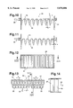
- FIG. 7 shows a front view of another embodiment of a mounting frame
- FIG. 8 shows a sectional view of the embodiment according to FIG. 7, taken along line VIII--VIII;
- FIG. 9 shows a sectional view similar to that of FIG. 8, but of a different embodiment, with the lamella grid in the fully open position;
- FIG. 10 shows a cross-sectional representation to that of FIG. 9, but in a position with partially reduced air flow
- FIG. 11 shows a cross-sectional view identical to that of FIG. 9, but with the flow cross-section fully closed;
- FIG. 12 shows a front view similar to that of FIG. 7, but of a different variant of a mounting frame
- FIG. 13 shows a sectional view of the mounting frame according to FIG. 12, taken along XIII--XIII, in the open position;
- FIG. 14 shows a sectional view of the representation of FIG. 13, taken along line XIV;
- FIG. 15 shows a view similar to that of FIG. 12, but of still another variant of a mounting frame with a lamella arrangement where the lamellae are slidable in the frame, one parallel to the other;
- FIG. 16 shows a top view of the mounting frame according to FIG. 15, viewed in the direction of arrow XVI.
- FIG. 1 shows a housing (1) of a heating and/or air-conditioning installation for a motor vehicle, including a vaporizer (2) and a heater (3).
- the housing (1) comprises an inlet (4) and an outlet (5) for an air flow that is introduced into the housing (1) in the direction of arrow (6), aided for example by a blower, and that leaves the housing (1) in the direction of arrow (7) in order to be discharged into the passenger compartment of a motor vehicle in a manner not shown in detail.
- the inlet (4) and the outlet (5) there are provided in this example two flow paths in the form of channels (8 and 9), the arrangement being such that one of the channels (8) can be opened and closed by a mounting frame (10) with hinged lamellae (11), while the channel (9) can be opened and closed by a mounting frame (10) of substantially identical design and likewise provided with lamellae (11), as will be described in more detail further below with reference to FIGS. 3 to 6.
- the channel (9) leads into a chamber (12) in which the heater (3) is arranged.
- the chamber (12) in its turn can be closed and opened, at its junction with the outlet chamber (13) extending next to the channel (8) behind the mounting frame (10), by another mounting frame (10') of principally the same design as the mounting frame (10) in the channel (8 and 9).
- the swing angle of the lamellae permits the air flow to be directed, whereby improved intermixing of two air flows can be achieved.
- the three mounting frame (10 and 10') provided with the lamellae (11) are disposed in substantially star-like arrangement and can be introduced, in a direction perpendicular to the drawing plane, into mounting openings of the housing (1), or can be fitted in corresponding receiving pockets (61) during assembly of the housing. As is indicated schematically, they are driven by a common drive (14), which is equipped with a rotatable cam disk (15).
- the design of the cam disk (15) is such that depending on the swing angle the opening and closing actions of the two mounting frames (10) are matched in such a way that one of the frame will be closed when the other one is open.
- the lamellae of the mounting frame (10') are in their fully open position when the lamellae (11) of the mounting frame in channel (9) are in their fully open position. They are closed when the lamellae (11) of the mounting frame in the channel (9) are also closed and the lamellae (11) of the mounting frame (10) in channel (8) are in their fully open position.
- the flow channel (8) is open.
- the flow channel (9) and the chamber (12) are closed.
- Fresh air entering the system in the direction of arrow (6) is guided through the vaporizer (2) and is permitted to enter the passenger compartment for cooling, in the direction indicated by arrow (7).
- the channel (8) is closed, whereas the channel (9) and the chamber (12) are open.
- Fresh air then flows through the vaporizer (2) and the heater (3), is dried and heated up and then permitted to enter the passenger compartment. If the lamellae (11) are partially open, as indicated in FIG. 1, then part of the fresh air will enter the passenger compartment directly, while another part will be directed additionally across the heater (3).
- FIG. 2 shows the analogous housing (1a) of a heating and/or air-conditioning installation of the prior art. Identical parts are designated here by the same reference numerals, supplemented only by an (a).
- the control means for opening or closing the channels which in the case of FIG.
- the means in the present case are configured as a control flap (17) supported to swing about the axis (16), which flap, when in its position (17a), closes the channel (9) and, thus, the chamber (12a), so that fresh air will be directed into the passenger compartment. In its position (17) the flap closes the channel (8a) so that in this position the air will be guided through the vaporizer and the heater (3a).
- the flap (17) being designed as a double-armed lever, requires relatively much space for its pivotal movement. This has the result that the overall length (L 2 ) of the prior-art installation is greater than the overall length (L 1 ) of the installation according to the invention, as indicated for comparison in FIG. 1.
- the length L 1 is equal only to approximately 0.6 times the length of L 2 . In the case of smaller opening angles, the air flow may become layered, and this phenomenon may obstruct effective intermixing.
- FIGS. 3 to 6 show the structure of the mounting frames 10 and 10' according to FIG. 1.
- the frames consist of a frame (18) whose dimensions are adapted to the dimensions of the channels (8) and (9), respectively, or to the outlet from the chamber (12), and which supports the ends of the lamellae, the latter being provided with pivot pins (19).
- Each of the lamellae (11) has one of its longitudinal edges mounted, via a firmly attached lug (20), on a common adjusting lever (21) so that the lamellae can be adjusted by means of a common drive.
- FIGS. 7 and 8 show a variant of a mounting frame with lamella grid insofar as in this case no hinged lamellae (11) are arranged in the frame (24); instead, drop-shaped flow profiles that taper in a direction opposite to the direction of flow (25) are distributed over the rectangular cross-section. All these lamellae (26), that are configured as flow profiles, are each provided with an end cap (27) that points in a direction opposite to the direction of flow and that can be displaced relative to the fixed portion (26) of the profile lamellae, in the direction indicated by arrows (28)--as can be seen in FIG. 8.
- FIG. 8 shows a variant of a mounting frame with lamella grid insofar as in this case no hinged lamellae (11) are arranged in the frame (24); instead, drop-shaped flow profiles that taper in a direction opposite to the direction of flow (25) are distributed over the rectangular cross-section. All these lamellae (26), that are configured as flow profiles, are each provided with an end
- FIG. 8 illustrates the position in which the cap portions (27), being again arranged on a common sliding frame (29), have been moved into an intermediate position between the profile lamellae (26) which are arranged at an equal spacing (a).
- This position permits a reduced flow through the mounting frame (24).
- the cap portions (27) are moved farther to the left until they completely close the free space between neighboring profiles (26), then the free cross-section is fully closed.
- the flow cross-section is fully open.
- the sliding frame (29) is retained in a guide--not shown in detail--for displacement in the direction of arrow (28).
- FIGS. 9 to 11 show a variant of a mounting frame (31) that operates principally in the same manner as the grid frame according to FIGS. 7 and 8.
- a number of lamellae (33) with a drop-shaped flow profile are provided in the mounting frame (31) in equally spaced distribution over the cross-sectional surface, and again their heads, that point in a direction opposite to the direction of flow (25), are arranged in a frame (32) capable of sliding relative to the frame (31).
- passage openings (35) of circular cross-section are formed between the movable heads (34) and the fixed profiles (33).
- the heads (34) cover just half of the free flow cross-section between neighboring lamella profiles (33), because the mutual spacing between all profiles is such that the free passage width between two profiles (33) is equal to the value (b). Due to the particular design of the opening (35) between the head (34) and the profile element (33), however, S-shaped flow channels are obtained on each profile (33, 34), in the position illustrated in FIG.
- FIG. 11 finally shows the closed position in which the sliding frame (32) has been displaced from the right to the left by an amount (b). The flow cross-section is fully closed in this position.
- FIGS. 12 to 14 show another variant of a mounting frame using a closure grid with lamellae (36) in the form of a flow profile.
- two substantially equal arrays of lamella profiles (36) and (37) are provided, with the lamella profiles (37) arranged in a stationary part, serving as mounting frame, and the lamellae (36) arranged in a frame (39) that can be displaced relative to the frame (38) in the flow direction (25) and in opposite direction, in the sense indicated by arrows (40).
- the dimensions are selected in such a way that the free flow width (b) between the lamellae (37) corresponds to the width of the individual lamella profiles (37 and 36).
- the profiles (36) can be moved into the space between the profiles (37) in a manner such that the free flow cross-section between the lamella profiles (37) becomes fully closed.
- connection pieces (41) located between the fixed lamella profiles (27) at their front ends, which connection pieces serve to provide a terminal portion at the upper and lower ends of the movable lamella profiles (36).
- FIGS. 15 and 16 finally show a last variant of a mounting frame (42) comprising an array of lamellae (34) mounted in a guide in the frame (42) for being displaced in parallel one to the other, in the manner of shutters.
- the mounting frame (42) which just like the other mounting frames illustrated in the previous figures is conveniently made from a plastic material, is provided with two lamella arrays (43) and (44), each of which individually closes or opens a right-hand or left-hand flow opening (45) or (46), respectively.
- groove-like guides (47) for the lamellae (44) and (43), respectively, are provided in the frame (42), which serve as guides for the upper and lower edges of the lamellae (43 and 44).
- the innermost lamella of each set (43 and 44) is connected, via a toothed rod (48), with a bevel gear (49) that engages the bevel pinion (51) of an electric motor (50). As appears from FIG.
- FIG. 15 thus shows the toothed rod (48) in its left position, in which the lamella (44) connected to it via the pivot lug (52) has been moved to its outermost left position. Since this lamella (44)--just as all other lamellae (44)--is provided with a guide edge (53) on both its lateral edges, each lamella that is driven by the toothed rod (48) will entrain its neighboring lamella so that in the case of the embodiment illustrated in FIG. 15 the displaceable lamellae (44) are all in their left end positions so that the opening (46) is clear.
- the second toothed rod (48') occupies the position illustrated in FIG. 15, with its pivot lug in the position facing the center of the frame (42), in which the innermost lamella (43), which just as the lamellae (44) is provided with guide edges (53) on both ends, has entrained the respective neighboring lamellae so that the three lamellae (43) all overlap each other and close the flow opening (45) in full.
- Such a design may be employed with advantage, for example, when flow channels must be alternately opened and closed in the housing of the heating and/or air-conditioning installation, as has been described above with reference to FIG. 1 and the channels (8 and 9).
- FIG. 16 show once more, by way of comparison of the required mounting dimensions, a solution where a hinged flap (54) is used for opening or closing the respective flow channels, that are now formed by the openings (46 and 45). It can be clearly seen that, due to the swing radius of the flap (54) and the housing configuration required for this purpose, a considerably larger overall space is needed in this case.
Landscapes
- Engineering & Computer Science (AREA)
- Mechanical Engineering (AREA)
- Physics & Mathematics (AREA)
- Thermal Sciences (AREA)
- Chemical & Material Sciences (AREA)
- Combustion & Propulsion (AREA)
- General Engineering & Computer Science (AREA)
- Air-Conditioning For Vehicles (AREA)
- Air-Flow Control Members (AREA)
Applications Claiming Priority (3)
| Application Number | Priority Date | Filing Date | Title |
|---|---|---|---|
| DE4442000.5 | 1994-11-28 | ||
| DE4442000A DE4442000A1 (de) | 1994-11-28 | 1994-11-28 | Heizungs- und/oder Klimaeinrichtung |
| PCT/EP1995/004462 WO1996016827A1 (de) | 1994-11-28 | 1995-11-14 | Heizungs- und/oder klimaeinrichtung |
Publications (1)
| Publication Number | Publication Date |
|---|---|
| US5878806A true US5878806A (en) | 1999-03-09 |
Family
ID=6534144
Family Applications (1)
| Application Number | Title | Priority Date | Filing Date |
|---|---|---|---|
| US08/682,664 Expired - Fee Related US5878806A (en) | 1994-11-28 | 1995-11-14 | Heating and/or air-conditioning installation |
Country Status (8)
| Country | Link |
|---|---|
| US (1) | US5878806A (ko) |
| EP (1) | EP0740617B1 (ko) |
| JP (1) | JP2908032B2 (ko) |
| KR (1) | KR100419794B1 (ko) |
| BR (1) | BR9506595A (ko) |
| DE (2) | DE4442000A1 (ko) |
| ES (1) | ES2119497T3 (ko) |
| WO (1) | WO1996016827A1 (ko) |
Cited By (22)
| Publication number | Priority date | Publication date | Assignee | Title |
|---|---|---|---|---|
| EP1044833A2 (en) * | 1999-04-13 | 2000-10-18 | Calsonic Kansei Corporation | Air conditioning apparatus for vehicle |
| US6189801B1 (en) * | 1998-05-16 | 2001-02-20 | Behr Gmbh & Co. | Device for heating and/or air conditioning a vehicle interior |
| EP1138532A1 (en) * | 2000-02-10 | 2001-10-04 | Korea Delphi Automotive Systems Corporation | Air conditioning system for automobile and door assembly thereof |
| US20020000307A1 (en) * | 2000-05-18 | 2002-01-03 | Walter Denk | Flow control device for gas stream |
| US20020004368A1 (en) * | 2000-05-18 | 2002-01-10 | Walter Denk | Flap for an air-guide duct |
| US6607029B2 (en) * | 1997-03-25 | 2003-08-19 | Valeo Climatisation | Heating and ventilating apparatus for a motor vehicle with selective control in different zones of the cabin |
| US20040069481A1 (en) * | 2001-02-13 | 2004-04-15 | Toshiyuki Ebara | On-vehicle air-conditioner for air-conditioning |
| US6761210B1 (en) * | 1999-04-30 | 2004-07-13 | Daimlerchrysler Ag | Airconditioner for a passenger cell of a vehicle |
| US6772833B2 (en) * | 2002-07-23 | 2004-08-10 | Visteon Global Technologies, Inc. | HVAC system with modular inserts |
| US6786278B2 (en) * | 2000-06-23 | 2004-09-07 | Halla Climate Control Corp. | Compact air conditioner for automobiles |
| US6823935B1 (en) * | 1998-04-11 | 2004-11-30 | Daimlerchrysler Ag | Heating or air-conditioning system |
| US20050217738A1 (en) * | 2002-08-16 | 2005-10-06 | Dietrich Klingler | Roller belt cassette for use in a control device |
| US6971440B1 (en) * | 1997-07-24 | 2005-12-06 | Behr Gmbh & Co. | Heating or air-conditioning system for a motor vehicle |
| US6994157B1 (en) * | 1998-02-04 | 2006-02-07 | Daimlerchrysler Ag | Air conditioner |
| US20060060343A1 (en) * | 2002-06-21 | 2006-03-23 | Behr Gmbh & Co. Kg | Modular heating and or air conditioning system for a motor vehicle |
| US20060073780A1 (en) * | 2004-09-29 | 2006-04-06 | Caterpillar Inc. | Airflow control system |
| US20090013706A1 (en) * | 2007-07-10 | 2009-01-15 | Denso Corporation | Air conditioning apparatus for vehicle |
| US20100006258A1 (en) * | 2008-07-10 | 2010-01-14 | Gerald Richter | Vehicle air conditioner |
| US20100017038A1 (en) * | 2008-07-18 | 2010-01-21 | Liu jing-ming | Device For Controlling A Fixed-Capacity Compressor |
| US20120138174A1 (en) * | 2010-12-03 | 2012-06-07 | Hyundai Motor Company | Apparatus for regulating flow rate of cooling air for vehicle and cooling apparatus for hybrid vehicle using the same |
| US20120305818A1 (en) * | 2011-06-03 | 2012-12-06 | GM Global Technology Operations LLC | Active aero shutters |
| US10518610B2 (en) | 2016-03-25 | 2019-12-31 | Ford Global Technologies Llc | Air outlet assemblies for vehicle ventilation systems |
Families Citing this family (23)
| Publication number | Priority date | Publication date | Assignee | Title |
|---|---|---|---|---|
| DE19631024B4 (de) * | 1996-08-01 | 2005-11-10 | Behr Gmbh & Co. Kg | Heiz- oder Klimaanlage |
| DE19632147B4 (de) * | 1996-08-09 | 2005-09-01 | Behr Gmbh & Co. Kg | Heiz- oder Klimaanlage |
| DE19637783A1 (de) * | 1996-09-17 | 1998-03-26 | Mannesmann Vdo Ag | Heizungs- und/oder Klimaeinrichtung |
| DE19644159A1 (de) * | 1996-10-24 | 1998-04-30 | Behr Gmbh & Co | Heiz- oder Klimaanlage |
| FR2758769B1 (fr) | 1997-01-29 | 1999-04-02 | Valeo Climatisation | Registre a volets multiples, notamment pour un systeme de climatisation de vehicule automobile |
| DE19726535C1 (de) * | 1997-06-23 | 1998-05-28 | Daimler Benz Ag | Heizungs- oder Klimaanlage für Fahrzeuge |
| FR2768662B1 (fr) * | 1997-09-19 | 2000-01-28 | Valeo Climatisation | Dispositif de chauffage/climatisation de vehicule automobile comportant un obturateur de reglage de flux d'air |
| DE19748425C1 (de) * | 1997-11-03 | 1998-10-29 | Daimler Benz Ag | Klimaanlage |
| DE19757194B4 (de) * | 1997-12-22 | 2010-06-02 | Behr Gmbh & Co. Kg | Vorrichtung zur Luftmengensteuerung und Luftverteilung in Heizungs- und Klimageräten |
| DE19854539C1 (de) | 1998-11-26 | 2000-04-06 | Daimler Chrysler Ag | Belüftungsvorrichtung für Fahrzeuge |
| US6453991B1 (en) * | 1999-03-29 | 2002-09-24 | Calsonickansei Corporation | Automotive air conditioner |
| DE19949932C2 (de) * | 1999-10-16 | 2003-08-21 | Daimler Chrysler Ag | Luftsteuerorgan für Luftauslässe in Belüftungs-, Heizungs- und/oder Klimaanlage von Fahrzeugen |
| DE10018268B4 (de) * | 2000-04-13 | 2010-11-04 | Behr Gmbh & Co. Kg | Luftstromsteuerelement für eine Heizungs- oder Klimaanlage eines Kraftfahrzeuges |
| DE10024693A1 (de) * | 2000-05-18 | 2001-11-22 | Behr Gmbh & Co | Steuereinrichtung für einen in einem Kanal geführten Gasstrom |
| DE10027284A1 (de) * | 2000-05-31 | 2001-12-06 | Behr Gmbh & Co | Einrichtung zum Verschwenken einer Klappe |
| DE10213177A1 (de) * | 2002-03-23 | 2003-10-02 | Behr Gmbh & Co | Steuereinrichtung für Heizungs- und/oder Klimaanlagen |
| DE10320750B4 (de) * | 2003-05-09 | 2006-06-14 | Daimlerchrysler Ag | Fahrzeug-Klimaanlage |
| DE102004027914A1 (de) * | 2003-06-26 | 2005-03-17 | Behr Gmbh & Co. Kg | Verschluss für mindestens eine Öffnung |
| DE102005022208A1 (de) * | 2005-05-13 | 2006-11-16 | Volkswagen Ag | Verfahren zum Betreiben einer Kraftfahrzeug-Klimaanlage |
| DE102005057392A1 (de) * | 2005-11-30 | 2007-05-31 | Behr Gmbh & Co. Kg | Klappenanordnung |
| JP2015101175A (ja) * | 2013-11-25 | 2015-06-04 | 株式会社日本クライメイトシステムズ | 空調装置用ダンパ |
| JP6286190B2 (ja) * | 2013-11-25 | 2018-02-28 | 株式会社日本クライメイトシステムズ | 空調装置用ダンパ |
| JP2015123780A (ja) * | 2013-12-25 | 2015-07-06 | 株式会社ヴァレオジャパン | 車両用空調装置 |
Citations (7)
| Publication number | Priority date | Publication date | Assignee | Title |
|---|---|---|---|---|
| US3366141A (en) * | 1966-01-26 | 1968-01-30 | Richard N. Foster | Support for zone control dampers |
| US3894481A (en) * | 1972-04-03 | 1975-07-15 | American Warming Ventilation | Multi-blade damper |
| US4518012A (en) * | 1982-08-23 | 1985-05-21 | Hara Robert J O | Air damper assembly with movable blades |
| US4534507A (en) * | 1982-03-03 | 1985-08-13 | Honda Giken Kogyo Kabushiki Kaisha | Air temperature regulating apparatus for vehicles |
| US4852639A (en) * | 1987-04-13 | 1989-08-01 | Hitachi, Ltd. | Air conditioning system for vehicle |
| SU1643202A2 (ru) * | 1989-04-27 | 1991-04-23 | Запорожский автомобильный завод "Коммунар" | Устройство дл отоплени и вентил ции салона транспортного средства |
| US5162020A (en) * | 1990-03-30 | 1992-11-10 | Nippondenso Co., Ltd. | Automotive air-conditioner with variable-length damper |
Family Cites Families (7)
| Publication number | Priority date | Publication date | Assignee | Title |
|---|---|---|---|---|
| DE3203927A1 (de) * | 1981-09-15 | 1983-03-31 | Audi Nsu Auto Union Ag, 7107 Neckarsulm | Heiz- und belueftungseinrichtung fuer den fahrgastraum eines kraftfahrzeuges |
| CH654639A5 (de) * | 1982-01-18 | 1986-02-28 | Luwa Ag | Explosionsschutzventil an luftdurchlaessen, insbesondere fuer schutzraeume. |
| JPS611527A (ja) * | 1984-06-15 | 1986-01-07 | Hitachi Ltd | 自動車用空気調和装置 |
| DE3602120A1 (de) * | 1986-01-24 | 1987-08-06 | Guenter Junkes Heizung Klima G | Steuerklappe fuer ein kombiniertes zu- und abluftgeraet |
| DE3618292C3 (de) * | 1986-05-30 | 1995-12-07 | Rainer Herma | Motorisch betätigbares Druckventil für Kabinen von Eisenbahnwagen |
| DE3836374A1 (de) * | 1988-10-26 | 1990-01-11 | Daimler Benz Ag | Kuehlluftabdeckung fuer einen fahrzeugkuehler |
| DE4119474C2 (de) * | 1991-06-13 | 1995-02-23 | Opel Adam Ag | Heiz- oder Klimaanlage für den Fahrgastraum eines Kraftfahrzeuges |
-
1994
- 1994-11-28 DE DE4442000A patent/DE4442000A1/de not_active Withdrawn
-
1995
- 1995-11-14 EP EP95939273A patent/EP0740617B1/de not_active Expired - Lifetime
- 1995-11-14 US US08/682,664 patent/US5878806A/en not_active Expired - Fee Related
- 1995-11-14 DE DE59502826T patent/DE59502826D1/de not_active Expired - Lifetime
- 1995-11-14 JP JP8518122A patent/JP2908032B2/ja not_active Expired - Fee Related
- 1995-11-14 ES ES95939273T patent/ES2119497T3/es not_active Expired - Lifetime
- 1995-11-14 KR KR1019960704062A patent/KR100419794B1/ko not_active IP Right Cessation
- 1995-11-14 BR BR9506595A patent/BR9506595A/pt not_active IP Right Cessation
- 1995-11-14 WO PCT/EP1995/004462 patent/WO1996016827A1/de active IP Right Grant
Patent Citations (7)
| Publication number | Priority date | Publication date | Assignee | Title |
|---|---|---|---|---|
| US3366141A (en) * | 1966-01-26 | 1968-01-30 | Richard N. Foster | Support for zone control dampers |
| US3894481A (en) * | 1972-04-03 | 1975-07-15 | American Warming Ventilation | Multi-blade damper |
| US4534507A (en) * | 1982-03-03 | 1985-08-13 | Honda Giken Kogyo Kabushiki Kaisha | Air temperature regulating apparatus for vehicles |
| US4518012A (en) * | 1982-08-23 | 1985-05-21 | Hara Robert J O | Air damper assembly with movable blades |
| US4852639A (en) * | 1987-04-13 | 1989-08-01 | Hitachi, Ltd. | Air conditioning system for vehicle |
| SU1643202A2 (ru) * | 1989-04-27 | 1991-04-23 | Запорожский автомобильный завод "Коммунар" | Устройство дл отоплени и вентил ции салона транспортного средства |
| US5162020A (en) * | 1990-03-30 | 1992-11-10 | Nippondenso Co., Ltd. | Automotive air-conditioner with variable-length damper |
Cited By (39)
| Publication number | Priority date | Publication date | Assignee | Title |
|---|---|---|---|---|
| US6607029B2 (en) * | 1997-03-25 | 2003-08-19 | Valeo Climatisation | Heating and ventilating apparatus for a motor vehicle with selective control in different zones of the cabin |
| US7275586B2 (en) | 1997-07-24 | 2007-10-02 | Behr Gmbh & Co. | Heating or air-conditioning system for a motor vehicle |
| US20060042780A1 (en) * | 1997-07-24 | 2006-03-02 | Behr Gmbh & Co. | Heating or air-conditioning system for a motor vehicle |
| US6971440B1 (en) * | 1997-07-24 | 2005-12-06 | Behr Gmbh & Co. | Heating or air-conditioning system for a motor vehicle |
| US6994157B1 (en) * | 1998-02-04 | 2006-02-07 | Daimlerchrysler Ag | Air conditioner |
| US6823935B1 (en) * | 1998-04-11 | 2004-11-30 | Daimlerchrysler Ag | Heating or air-conditioning system |
| US6189801B1 (en) * | 1998-05-16 | 2001-02-20 | Behr Gmbh & Co. | Device for heating and/or air conditioning a vehicle interior |
| EP1044833A3 (en) * | 1999-04-13 | 2003-01-02 | Calsonic Kansei Corporation | Air conditioning apparatus for vehicle |
| US6609563B1 (en) | 1999-04-13 | 2003-08-26 | Calsonic Kansei Corporation | Vehicular air conditioning apparatus including a detachably installed mix door assembly |
| EP1044833A2 (en) * | 1999-04-13 | 2000-10-18 | Calsonic Kansei Corporation | Air conditioning apparatus for vehicle |
| US6814138B2 (en) * | 1999-04-13 | 2004-11-09 | Calsonic Kansei Corporation | Air conditioning apparatus for vehicle |
| US6761210B1 (en) * | 1999-04-30 | 2004-07-13 | Daimlerchrysler Ag | Airconditioner for a passenger cell of a vehicle |
| EP1138532A1 (en) * | 2000-02-10 | 2001-10-04 | Korea Delphi Automotive Systems Corporation | Air conditioning system for automobile and door assembly thereof |
| US6997240B2 (en) | 2000-05-18 | 2006-02-14 | Behr Gmbh & Co. | Flap for an air-guide duct |
| US7334628B2 (en) | 2000-05-18 | 2008-02-26 | Behr Gmbh & Co. | Flow control device for gas stream |
| US20020000307A1 (en) * | 2000-05-18 | 2002-01-03 | Walter Denk | Flow control device for gas stream |
| US20020004368A1 (en) * | 2000-05-18 | 2002-01-10 | Walter Denk | Flap for an air-guide duct |
| US6786278B2 (en) * | 2000-06-23 | 2004-09-07 | Halla Climate Control Corp. | Compact air conditioner for automobiles |
| US7066245B2 (en) * | 2001-02-13 | 2006-06-27 | Sanyo Electric Co., Ltd. | On-vehicle air-conditioner for air-conditioning |
| US20040069481A1 (en) * | 2001-02-13 | 2004-04-15 | Toshiyuki Ebara | On-vehicle air-conditioner for air-conditioning |
| US20060060343A1 (en) * | 2002-06-21 | 2006-03-23 | Behr Gmbh & Co. Kg | Modular heating and or air conditioning system for a motor vehicle |
| US7748441B2 (en) | 2002-06-21 | 2010-07-06 | Behr Gmbh & Co. Kg | Modular heating and/or air conditioning system for a motor vehicle |
| US6772833B2 (en) * | 2002-07-23 | 2004-08-10 | Visteon Global Technologies, Inc. | HVAC system with modular inserts |
| US20050217738A1 (en) * | 2002-08-16 | 2005-10-06 | Dietrich Klingler | Roller belt cassette for use in a control device |
| US7246788B2 (en) | 2002-08-16 | 2007-07-24 | Behr Gmbh & Co. Kg | Roller belt cassette for use in a control device |
| US20050233686A1 (en) * | 2002-08-16 | 2005-10-20 | Dietrich Klingler | Control device comprising a roller band cassette |
| US7670215B2 (en) | 2002-08-16 | 2010-03-02 | Behr Gmbh & Co. Kg | Control device comprising a roller band cassette |
| US7189158B2 (en) * | 2004-09-29 | 2007-03-13 | Caterpillar Inc | Airflow control system |
| US20060073780A1 (en) * | 2004-09-29 | 2006-04-06 | Caterpillar Inc. | Airflow control system |
| US20090013706A1 (en) * | 2007-07-10 | 2009-01-15 | Denso Corporation | Air conditioning apparatus for vehicle |
| US7967063B2 (en) | 2007-07-10 | 2011-06-28 | Denso Corporation | Air conditioning apparatus for vehicle |
| US8757245B2 (en) * | 2008-07-10 | 2014-06-24 | Halla Visteon Climate Control Corporation | Vehicle air conditioner |
| US20100006258A1 (en) * | 2008-07-10 | 2010-01-14 | Gerald Richter | Vehicle air conditioner |
| US20100017038A1 (en) * | 2008-07-18 | 2010-01-21 | Liu jing-ming | Device For Controlling A Fixed-Capacity Compressor |
| US9157672B2 (en) * | 2008-07-18 | 2015-10-13 | Valeo Systemes Thermiques | Device for controlling a fixed-capacity compressor |
| US20120138174A1 (en) * | 2010-12-03 | 2012-06-07 | Hyundai Motor Company | Apparatus for regulating flow rate of cooling air for vehicle and cooling apparatus for hybrid vehicle using the same |
| US20120305818A1 (en) * | 2011-06-03 | 2012-12-06 | GM Global Technology Operations LLC | Active aero shutters |
| US8807166B2 (en) * | 2011-06-03 | 2014-08-19 | GM Global Technology Operations LLC | Active aero shutters |
| US10518610B2 (en) | 2016-03-25 | 2019-12-31 | Ford Global Technologies Llc | Air outlet assemblies for vehicle ventilation systems |
Also Published As
| Publication number | Publication date |
|---|---|
| KR100419794B1 (ko) | 2004-05-31 |
| JPH09508875A (ja) | 1997-09-09 |
| EP0740617A1 (de) | 1996-11-06 |
| WO1996016827A1 (de) | 1996-06-06 |
| EP0740617B1 (de) | 1998-07-15 |
| ES2119497T3 (es) | 1998-10-01 |
| BR9506595A (pt) | 1997-09-16 |
| DE59502826D1 (de) | 1998-08-20 |
| DE4442000A1 (de) | 1996-05-30 |
| KR970700601A (ko) | 1997-02-12 |
| JP2908032B2 (ja) | 1999-06-21 |
Similar Documents
| Publication | Publication Date | Title |
|---|---|---|
| US5878806A (en) | Heating and/or air-conditioning installation | |
| DE3203424C3 (de) | Klimaanlage für Kraftfahrzeuge | |
| US5399120A (en) | Air conditioning system control valve | |
| US6959754B2 (en) | Air conditioning system for a vehicle | |
| DE10351409B4 (de) | Fahrzeug-Klimaanlage | |
| EP1110769B1 (de) | Heizungs- oder Klimaanlage für ein Kraftfahrzeug | |
| KR100316163B1 (ko) | 공기조화장치 | |
| DE19858727B4 (de) | Klimaanlage für ein Fahrzeug | |
| US6743089B2 (en) | Air-guiding nozzle | |
| DE29504860U1 (de) | Nach dem Mischluftprinzip arbeitendes Heiz- bzw. Klimagerät | |
| US6106386A (en) | Air flow mixing apparatus | |
| DE19919975C1 (de) | Klimaanlage für eine Fahrgastzelle eines Fahrzeugs | |
| DE19816329C2 (de) | Heizungs- und Klimaanlage | |
| DE112014001663T5 (de) | Fahrzeugklimaanlage | |
| KR101154477B1 (ko) | 공조모드 구현용 도어 조립체 | |
| DE102007013432B4 (de) | Warmluftkanal für ein Klimagerät eines Kraftfahrzeuges | |
| DE4243165A1 (de) | Klimagerät für ein Kraftfahrzeug | |
| US3752223A (en) | Air conditioning apparatus for automotive vehicles | |
| DE10345188A1 (de) | Fahrzeugklimaanlage | |
| KR101393091B1 (ko) | 차량용 공조장치 | |
| EP0090136B1 (de) | Heizungs- und Belüftungsanlage für Kraftfahrzeuge | |
| EP0296556B1 (en) | Air-conditioning device for motor vehicles | |
| US11351840B2 (en) | Air conditioner for vehicle | |
| DE112020002521T5 (de) | Klimagerät für fahrzeuge | |
| DE19951101C1 (de) | Klimaanlage für eine Fahrgastzelle eines Fahrzeugs |
Legal Events
| Date | Code | Title | Description |
|---|---|---|---|
| AS | Assignment |
Owner name: BEHR GMBH & CO., GERMANY Free format text: ASSIGNMENT OF ASSIGNORS INTEREST;ASSIGNORS:DENK, WALTER;MARTIN, RALF;RAULAND, WERNER;AND OTHERS;REEL/FRAME:008135/0524;SIGNING DATES FROM 19960715 TO 19960718 |
|
| FPAY | Fee payment |
Year of fee payment: 4 |
|
| FPAY | Fee payment |
Year of fee payment: 8 |
|
| REMI | Maintenance fee reminder mailed | ||
| LAPS | Lapse for failure to pay maintenance fees | ||
| STCH | Information on status: patent discontinuation |
Free format text: PATENT EXPIRED DUE TO NONPAYMENT OF MAINTENANCE FEES UNDER 37 CFR 1.362 |
|
| FP | Lapsed due to failure to pay maintenance fee |
Effective date: 20110309 |