US5850737A - Process for controlling the charging pressure in an exhaust gas turbocharger with an adjustable turbine geometry - Google Patents
Process for controlling the charging pressure in an exhaust gas turbocharger with an adjustable turbine geometry Download PDFInfo
- Publication number
- US5850737A US5850737A US08/706,318 US70631896A US5850737A US 5850737 A US5850737 A US 5850737A US 70631896 A US70631896 A US 70631896A US 5850737 A US5850737 A US 5850737A
- Authority
- US
- United States
- Prior art keywords
- pressure
- control
- charging pressure
- exhaust gas
- process according
- Prior art date
- Legal status (The legal status is an assumption and is not a legal conclusion. Google has not performed a legal analysis and makes no representation as to the accuracy of the status listed.)
- Expired - Fee Related
Links
Images
Classifications
-
- F—MECHANICAL ENGINEERING; LIGHTING; HEATING; WEAPONS; BLASTING
- F02—COMBUSTION ENGINES; HOT-GAS OR COMBUSTION-PRODUCT ENGINE PLANTS
- F02B—INTERNAL-COMBUSTION PISTON ENGINES; COMBUSTION ENGINES IN GENERAL
- F02B37/00—Engines characterised by provision of pumps driven at least for part of the time by exhaust
- F02B37/12—Control of the pumps
- F02B37/24—Control of the pumps by using pumps or turbines with adjustable guide vanes
-
- F—MECHANICAL ENGINEERING; LIGHTING; HEATING; WEAPONS; BLASTING
- F02—COMBUSTION ENGINES; HOT-GAS OR COMBUSTION-PRODUCT ENGINE PLANTS
- F02D—CONTROLLING COMBUSTION ENGINES
- F02D41/00—Electrical control of supply of combustible mixture or its constituents
- F02D41/0002—Controlling intake air
- F02D41/0007—Controlling intake air for control of turbo-charged or super-charged engines
-
- F—MECHANICAL ENGINEERING; LIGHTING; HEATING; WEAPONS; BLASTING
- F02—COMBUSTION ENGINES; HOT-GAS OR COMBUSTION-PRODUCT ENGINE PLANTS
- F02D—CONTROLLING COMBUSTION ENGINES
- F02D41/00—Electrical control of supply of combustible mixture or its constituents
- F02D41/02—Circuit arrangements for generating control signals
- F02D41/14—Introducing closed-loop corrections
- F02D41/1401—Introducing closed-loop corrections characterised by the control or regulation method
- F02D41/1404—Fuzzy logic control
-
- Y—GENERAL TAGGING OF NEW TECHNOLOGICAL DEVELOPMENTS; GENERAL TAGGING OF CROSS-SECTIONAL TECHNOLOGIES SPANNING OVER SEVERAL SECTIONS OF THE IPC; TECHNICAL SUBJECTS COVERED BY FORMER USPC CROSS-REFERENCE ART COLLECTIONS [XRACs] AND DIGESTS
- Y02—TECHNOLOGIES OR APPLICATIONS FOR MITIGATION OR ADAPTATION AGAINST CLIMATE CHANGE
- Y02T—CLIMATE CHANGE MITIGATION TECHNOLOGIES RELATED TO TRANSPORTATION
- Y02T10/00—Road transport of goods or passengers
- Y02T10/10—Internal combustion engine [ICE] based vehicles
- Y02T10/12—Improving ICE efficiencies
Definitions
- This invention relates to a process for controlling the charging pressure in an internal-combustion engine exhaust gas turbocharger having an adjustable turbine geometry, to a predetermined operating-point-dependent desired value.
- German Patent Document DE 40 25 901 C1 discloses a process for preventing the occurrence of uncontrolled super elevations of pressure after a positive load change when the charging pressure p2 in the exhaust pipe upstream of the turbine is still rising. Thereby the internal-combustion engine needs no longer exhaust against a super elevated exhaust back pressure, facilitating increased efficiency of the internal-combustion engine.
- a limit pressure switch is provided in the exhaust pipe to control the exhaust back pressure p3.
- the limit pressure switch changes its switching condition upon the occurrence of a certain limit pressure; that is, in the case of an exhaust back pressure which exceeds a limit pressure or a threshold value, the limit pressure switch is changed from a closed position into an open position.
- the disadvantage of this process is that, in the case of such a monitoring of the exhaust back pressure p3, only the momentary exhaust back pressure existing upstream of the turbine is detected and compared with a limit or threshold value. This measurement does not reflect the current atmospheric pressure (that is, the elevation above the sea level); also, the current charging pressure p2 cannot be taken into account during monitoring.
- the limit pressure switch permits only a larger or smaller differentiation but not continuous evaluation.
- Japanese Patent Document JP 62-182437 discloses a process for controlling the charging pressure in an internal-combustion engine exhaust gas turbocharger with an adjustable turbine geometry of the generic type referred to above.
- the above-mentioned disadvantages are mitigated by measuring the pressure difference between the exhaust gas pressure and the current charging pressure, rather than the absolute value of the exhaust gas pressure, for controlling exhaust gas turbocharger. It is a disadvantage of this process, however, that, according to the block diagram described therein, a high-expenditure sequence of successive computing steps is required which are detected and evaluated by a high-expenditure control device.
- This object is achieved according to the invention by means of a process which, in transient operation of the internal-combustion engine, in the case of a positive load change during the rise of the charging pressure, prevents in a simple manner unacceptable exhaust back pressure super elevations which (because of the correspondingly occurring negative load change) tend to counteract the engine torque, reducing it in an unacceptable manner.
- unacceptable super elevations of pressure are detected directly by a comparison of the exhaust back pressure with an engine operation-dependent limit pressure, taking into account the current charging pressure.
- the charge pressure is controlled by adjusting the blade position of the variable turbine geometry exhaust gas turbocharger toward the opening direction, so that the exhaust gas pressure in front of the turbine is reduced to the maximum permissible limit pressure.
- Such adjustment is performed by means of a control element connected with a turbine guide apparatus, based on the regulator current emitted by a fuzzy control unit.
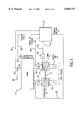
- FIG. 1 is a schematic diagram of an advantageous arrangement for implementing the process according to the invention
- FIG. 2 is a functional block diagram of a method of operation of the electronic control unit according to the invention which has the reference number 20 in FIG. 1;
- FIG. 3 is functional block diagram of the method of operation of the fuzzy control unit according to the invention illustrated in FIG. 2.
- FIG. 1 illustrates an internal-combustion engine 11 with an exhaust gas turbocharger 12 whose turbine 13 is arranged in the exhaust pipe 14 and whose compressor 15 is arranged in the intake pipe 16.
- its turbine 13 has a turbine guide apparatus 17, which for reasons of clarity, is outlined only schematically in the drawing.
- the turbine guide apparatus 17 is actuated by a servo motor 18 which, in turn, can be controlled by way of the control line 19 by an electronic control unit 20.
- a signal which corresponds to the current charging pressure p2 is fed to the control unit 20 by a sensor 21, via a measuring line 22.
- a sensor 23 and a measured-value line 24 supply a signal which corresponds to the current exhaust gas pressure p3 in front of the turbine 13, while a sensor 25 and a measured-value line 26 provide a signal which corresponds to the current rotational speed n of the internal-combustion engine, both of which signals are fed to the electric control unit 20.
- the control unit 20 also receives a signal which corresponds to the current injection quantity of the internal-combustion engine 11.
- the current injection quantity is determined from the position of the accelerator pedal (not shown), which in turn is determined by the driver in the case of a positive load change, as, for example, from idling to a full load.
- the turbine guide apparatus 17 is first changed into a closed position; that is, into a position which reduces to a minimum the approach flow cross-section for the exhaust gases onto the turbine 13. Because the approach flow cross-section of the turbine 13 is constructed to be very small, the exhaust gas pressure p3 rises very rapidly so that, even before the charging pressure p2 has reached the desired value p2 corresponding to this operating point, the exhaust back pressure p3 is considerably super elevated which is a detriment to the efficiency of the internal-combustion engine 11. As a result, it is necessary that the super elevation of the exhaust back pressure p3 is monitored and controlled so that an optimal torque buildup can be achieved which results in a high efficiency of the internal-combustion engine 11.
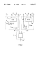
- FIG. 2 is a functional block diagram of an electronic control unit 20 which has a control structure for controlling the exhaust gas turbocharger 12 with a variable turbine geometry, by means of a control difference block 31, a monitoring block 32 and a controller 33.
- the control difference block 31 and the monitoring block 32 furnish the required control deviations or monitoring values for the controller 33 which, as illustrated in FIG. 1, controls the servo motor 18 by way of a regulator current 34.
- the control element 18 causes the opening or closing of the turbine guide apparatus with respect to the approach flow cross-section.
- the current charging pressure p2 of the internal-combustion engine 11 is received from the sensor 21 via the measured-value line 22.
- a fundamental charging pressure value is determined in the control difference block 31 from an applicable characteristic charging pressure diagram, based on the detected measured data by way of the sensors 25 and 27 as a function of the rotational engine speed and the injection quantity, as illustrated by block 37.
- an elevation-dependent correction value is formed in block 38, based on atmospheric pressure and an applicable characteristic correction curve. The sum of the fundamental charging pressure value and of the elevation-dependent correction value results in a desired charging pressure value p2 des at which the internal-combustion engine 11 achieves an optimal efficiency.
- the differential pressure between the desired charging pressure value p2 des and the current charging pressure p2 behind the turbine 15 in the intake pipe 16 is determined by subtraction. This differential pressure is emitted as the control difference dp2 by the control difference block 31, and is transmitted to the controller 33.
- a maximum permissible differential pressure P3* max is determined in an applicable characteristic differential pressure diagram 39, as a function of rotational engine speed and injection quantity (from the data of the sensors 25, 27).
- the current value of the exhaust back pressure p3 detected by the sensor 23 is compared to the actual value of the charging pressure p2, resulting in an effective differential pressure p3*.
- the advantage of this determination of differential pressure is that the monitoring is largely independent of the current atmospheric pressure; in addition, the currently existing charging pressure p2 is taken into account during the monitoring which takes place in this monitoring block.
- a control quantity dp3* is now determined by subtraction of the current differential pressure p3* from the maximum permissible differential pressure p3* max .
- This control quantity dp3* is provided as another input to the controller 33.
- the control quantity dp3* can assume values which are negative, approximately equal to zero or zero as well as positive.
- a control quantity dp3* which is much lower than zero, for example, means that the exhaust back pressure p3 is too high for optimal torque buildup.
- the controller 33 must be designed such that in this case the charge pressure p2 is controlled by adjusting the blade position of the exhaust gas turbocharger 12 with the variable turbine geometry in the opening direction. In this manner, the exhaust gas pressure p3 in front of the turbine 13 is therefore reduced to the maximum permissible limit pressure.
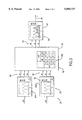
- a fuzzy logic control unit is used as the controller 33, as illustrated in FIG. 3.
- Such a fuzzy logic controller 33 has the advantage that, in addition to the control deviation dp2, other control quantities can be used to calculate the regulator current 34.
- other control quantities can be used to calculate the regulator current 34.
- an additional control element limitation can be provided from the start in order to permit only certain operating conditions, as described below.
- the fuzzy logic controller 33 implements a first step 51--a fuzzification. That is, for example, the input quantities dp3* and dp2 are divided into the linguistic terms “negative” (NE), “Positive” (PO) and “zero” (ZE) (designated generally by reference number 56, as illustrated in blocks 41A and 41B.
- a second step 52 by means of an inference matrix 52A, the relationship between the input quantities dp2 and dp3* and the output quantity I is defined in an application-specific manner.
- the output quantity I is also divided into the linguistic terms "negative” (NE), “positive” (PO) and “zero” (ZE). This division can be differentiated further, for example, into “very much smaller” and “very much larger” or the like, if it is required by the control system.
- the inference matrix 52A in block 42 assigns a linguistic term for the output quantity I to possible combinations of the linguistic terms of the input quantity dp3* (1st line) and dp2 (1st column).
- the linguistic term 57 for the output quantity I is converted into a regulator current 34 in a third step 53--a defuzzification--according to block 43.
- the function and method of operation of the fuzzy controller 33 is described for the case in which the dp3* input is "negative" (NE).
- NE exhaust back pressure
- the inference matrix 52A in block 42 only the linguistic terms NE and ZE are possible as the output quantity for the regulator current 34, so that positive reinforcement range of the fuzzy logic controller 33 is reduced.
- the opening of the turbine blades (which are open in the case of an output variable NE) is accelerated.
- the fuzzy logic controller 33 has a P-behavior with respect to the dp2-input.
- the control member 18 of the turbine guide apparatus 17 is constructed as a servo motor with an I-characteristic so that, in the case of a constant regulator current 34, because of the I-characteristic, a constant control speed can be achieved.
- control element 18 with a P-behavior is used for the turbine guide apparatus 17, in which case a fuzzy logic controller 33 with an I- or PI-behavior must then be used in order to avoid remaining control differences.
- the conversion of the linguistic output terms 57 takes place into an analogous current value 34 according to the known defuzzification methods, which is input to the servo motor 18 to drive the turbine guide apparatus 17, as shown in FIG. 1.
Landscapes
- Engineering & Computer Science (AREA)
- Chemical & Material Sciences (AREA)
- Combustion & Propulsion (AREA)
- Mechanical Engineering (AREA)
- General Engineering & Computer Science (AREA)
- Physics & Mathematics (AREA)
- Fuzzy Systems (AREA)
- Mathematical Physics (AREA)
- Software Systems (AREA)
- Supercharger (AREA)
Applications Claiming Priority (2)
| Application Number | Priority Date | Filing Date | Title |
|---|---|---|---|
| DE19531871.4 | 1995-08-30 | ||
| DE19531871A DE19531871C1 (de) | 1995-08-30 | 1995-08-30 | Verfahren zur Regelung des Ladedrucks bei einer mittels eines Abgasturboladers mit verstellbarer Turbinengeometrie aufgeladenen Brennkraftmaschine |
Publications (1)
| Publication Number | Publication Date |
|---|---|
| US5850737A true US5850737A (en) | 1998-12-22 |
Family
ID=7770740
Family Applications (1)
| Application Number | Title | Priority Date | Filing Date |
|---|---|---|---|
| US08/706,318 Expired - Fee Related US5850737A (en) | 1995-08-30 | 1996-08-30 | Process for controlling the charging pressure in an exhaust gas turbocharger with an adjustable turbine geometry |
Country Status (5)
| Country | Link |
|---|---|
| US (1) | US5850737A (it) |
| DE (1) | DE19531871C1 (it) |
| FR (1) | FR2738287B1 (it) |
| GB (1) | GB2304823B (it) |
| IT (1) | IT1284238B1 (it) |
Cited By (19)
| Publication number | Priority date | Publication date | Assignee | Title |
|---|---|---|---|---|
| FR2788560A1 (fr) * | 1999-01-14 | 2000-07-21 | Daimler Chrysler Ag | Moteur a combustion interne equipe d'une unite pilotable de reglage du debit de refoulement d'air d'alimentation |
| WO2001055575A1 (en) * | 2000-01-25 | 2001-08-02 | International Engine Intellectual Property Company, Llc | Control of a variable geometry turbocharger by sensing exhaust pressure |
| WO2001066921A1 (de) * | 2000-03-07 | 2001-09-13 | Robert Bosch Gmbh | Verfahren und vorrichtung zur regelung des ladedrucks einer brennkraftmaschine |
| US6295816B1 (en) | 2000-05-24 | 2001-10-02 | General Electric Company | Turbo-charged engine combustion chamber pressure protection apparatus and method |
| US6298718B1 (en) | 2000-03-08 | 2001-10-09 | Cummins Engine Company, Inc. | Turbocharger compressor diagnostic system |
| WO2003012272A1 (en) * | 2001-07-27 | 2003-02-13 | Detroit Diesel Corporation | Engine control based on exhaust back pressure |
| FR2829530A1 (fr) * | 2001-09-12 | 2003-03-14 | Renault | Procede et systeme de reglage du flux d'air dans le collecteur d'admission d'un moteur a combustion interne d'un vehicule automobile |
| US6830121B1 (en) * | 2001-10-10 | 2004-12-14 | Robert E. Johnson | Fuel economizer system |
| US20070151240A1 (en) * | 2006-01-04 | 2007-07-05 | Cummins, Inc. | Temperature determination technique for a turbocharger |
| US20070251233A1 (en) * | 2006-04-26 | 2007-11-01 | Dr. Ing. H.C. F. Porsche Ag | Method and control unit for adjusting a variable turbocharger turbine flow cross section |
| GB2460163A (en) * | 2008-05-19 | 2009-11-25 | Ford Global Tech Llc | Reducing the transient specific fuel consumption of a turbocharged i.c. engine having an electronically controlled turbine inlet flow control device |
| US20100083657A1 (en) * | 2008-09-24 | 2010-04-08 | Audi Ag | Method for Controlling and/or Adjusting a Charging Pressure of an Exhaust Gas Turbocharger as well as an Internal Combustion Engine |
| EP2307868A1 (fr) * | 2008-06-30 | 2011-04-13 | Renault S.A.S. | Systeme et procede de correction de la mesure d'un capteur de pression avant turbine |
| US20120017869A1 (en) * | 2010-07-26 | 2012-01-26 | Man Nutzfahrzeuge Osterreich Ag | Method and device for engine braking |
| EP2009264A3 (en) * | 2007-06-26 | 2014-08-06 | Hitachi Ltd. | Method and apparatus for controlling an internal combustion engine |
| US20170276067A1 (en) * | 2016-03-24 | 2017-09-28 | Ford Global Technologies, Llc | Methods and systems for boost control |
| CN110382847A (zh) * | 2017-04-05 | 2019-10-25 | 大众汽车有限公司 | 根据排气背压运行具有具备可变涡轮几何形状的废气涡轮增压器的内燃机的方法 |
| US11015538B2 (en) | 2018-11-22 | 2021-05-25 | Volkswagen Aktiengesellschaft | Method for controlling a supercharging system |
| US12025066B1 (en) * | 2023-03-28 | 2024-07-02 | Shanhai Jiao Tong University | Intelligent variable mode control method for variable altitude turbocharging system of diesel engine |
Families Citing this family (16)
| Publication number | Priority date | Publication date | Assignee | Title |
|---|---|---|---|---|
| GB9611015D0 (en) * | 1996-05-25 | 1996-07-31 | Holset Engineering Co | Variable geometry turbocharger control |
| DE19715237A1 (de) * | 1997-04-12 | 1998-10-15 | Daimler Benz Ag | Verfahren zur Steuerung bzw. Regelung des Ladeluftmassenstroms einer Brennkraftmaschine mit einem Abgasturbolader mit verstellbarer Turbinengeometrie |
| DE19750445C1 (de) * | 1997-11-14 | 1999-06-24 | Daimler Chrysler Ag | Verfahren zur Steuerung eines VTG-Abgasturboladers |
| DE19808832C2 (de) * | 1998-03-03 | 2000-04-13 | Daimler Chrysler Ag | Verfahren zur Regelung des Ladeluftmassenstroms einer aufgeladenen Brennkraftmaschine |
| DE19814572B4 (de) * | 1998-04-01 | 2008-05-15 | Daimler Ag | Verfahren und Bremseinrichtung für einen Abgasturbolader mit variabler Turbinengeometrie |
| DE19821902A1 (de) * | 1998-05-15 | 1999-11-18 | Siemens Ag | Verfahren zur Regelung des Ladedrucks |
| DE19844213C1 (de) * | 1998-09-26 | 1999-05-27 | Daimler Chrysler Ag | Verfahren zur Regelung oder Steuerung einer aufgeladenen Brennkraftmaschine |
| DE19844214C1 (de) * | 1998-09-26 | 1999-05-27 | Daimler Chrysler Ag | Verfahren zur Regelung oder Steuerung einer aufgeladenen Brennkraftmaschine |
| DE19846526C1 (de) * | 1998-10-09 | 2000-04-20 | Daimler Chrysler Ag | Prüfverfahren für eine aufgeladene Brennkraftmaschine |
| FR2840027B1 (fr) * | 2002-05-24 | 2004-10-15 | Renault Sa | Dispositif de commande d'un moteur suralimente comprenant l'utilisation d'un element de logique loue |
| US6928817B2 (en) | 2002-06-28 | 2005-08-16 | Honeywell International, Inc. | Control system for improved transient response in a variable-geometry turbocharger |
| US6672060B1 (en) * | 2002-07-30 | 2004-01-06 | Ford Global Technologies, Llc | Coordinated control of electronic throttle and variable geometry turbocharger in boosted stoichiometric spark ignition engines |
| FR2856431B1 (fr) * | 2003-06-20 | 2006-06-23 | Renault Sa | Dispositif de commande d'un moteur suralimente comprenant l'utilisation d'un element de logique floue |
| FR2885648A1 (fr) * | 2005-05-12 | 2006-11-17 | Renault Sas | Procede de commande d'un moteur de vehicule et moteur de vehicule comprenant un dispositif de suralimentation |
| FR2948977A3 (fr) * | 2009-08-07 | 2011-02-11 | Renault Sa | Procede de fonctionnement d'un systeme d'admission d'un moteur a combustion interne suralimente |
| US9217362B2 (en) | 2013-09-11 | 2015-12-22 | GM Global Technology Operations LLC | Two-stage turbocharger flow control |
Citations (7)
| Publication number | Priority date | Publication date | Assignee | Title |
|---|---|---|---|---|
| GB2172340A (en) * | 1985-03-08 | 1986-09-17 | Hitachi Shipbuilding Eng Co | Turbocharger for diesel engine and method of controlling same |
| JPS62182437A (ja) * | 1986-02-05 | 1987-08-10 | Toyota Motor Corp | 可変ノズル付過給機の制御方法 |
| DE3624248A1 (de) * | 1986-07-18 | 1988-01-28 | Daimler Benz Ag | Verfahren zur ladedruckabhaengigen steuerung des turbinenleitapparates des turboladers einer brennkraftmaschine |
| EP0323256A2 (en) * | 1987-12-29 | 1989-07-05 | Honda Giken Kogyo Kabushiki Kaisha | Supercharging pressure control method for internal combustion engines |
| JPH03105022A (ja) * | 1989-09-19 | 1991-05-01 | Ishikawajima Harima Heavy Ind Co Ltd | 可変容量ターボチャージャの制御装置 |
| US5174119A (en) * | 1990-08-16 | 1992-12-29 | Mercedes-Benz Ag | Process for controlling the boost pressure in an internal-combustion engine supercharged by an exhaust-gas turbocharger of adjustable turbine geometry |
| US5440879A (en) * | 1992-11-27 | 1995-08-15 | Iveco Fiat S.P.A. | Electronic control system for the speed of rotation of a variable geometry turbocompressor |
Family Cites Families (3)
| Publication number | Priority date | Publication date | Assignee | Title |
|---|---|---|---|---|
| US4428199A (en) * | 1979-02-28 | 1984-01-31 | Semco Instruments, Inc. | Turbocharger control system |
| DE2943729C2 (de) * | 1979-10-30 | 1984-06-07 | M.A.N. Maschinenfabrik Augsburg-Nürnberg AG, 8900 Augsburg | Steuerung einer selbstzündenden Brennkraftmaschine mit Stauaufladung |
| JPS6312829A (ja) * | 1986-07-02 | 1988-01-20 | Hitachi Ltd | タ−ボチヤ−ジヤ |
-
1995
- 1995-08-30 DE DE19531871A patent/DE19531871C1/de not_active Expired - Fee Related
-
1996
- 1996-07-29 IT IT96RM000540A patent/IT1284238B1/it active IP Right Grant
- 1996-08-19 GB GB9617376A patent/GB2304823B/en not_active Expired - Fee Related
- 1996-08-27 FR FR9610483A patent/FR2738287B1/fr not_active Expired - Fee Related
- 1996-08-30 US US08/706,318 patent/US5850737A/en not_active Expired - Fee Related
Patent Citations (7)
| Publication number | Priority date | Publication date | Assignee | Title |
|---|---|---|---|---|
| GB2172340A (en) * | 1985-03-08 | 1986-09-17 | Hitachi Shipbuilding Eng Co | Turbocharger for diesel engine and method of controlling same |
| JPS62182437A (ja) * | 1986-02-05 | 1987-08-10 | Toyota Motor Corp | 可変ノズル付過給機の制御方法 |
| DE3624248A1 (de) * | 1986-07-18 | 1988-01-28 | Daimler Benz Ag | Verfahren zur ladedruckabhaengigen steuerung des turbinenleitapparates des turboladers einer brennkraftmaschine |
| EP0323256A2 (en) * | 1987-12-29 | 1989-07-05 | Honda Giken Kogyo Kabushiki Kaisha | Supercharging pressure control method for internal combustion engines |
| JPH03105022A (ja) * | 1989-09-19 | 1991-05-01 | Ishikawajima Harima Heavy Ind Co Ltd | 可変容量ターボチャージャの制御装置 |
| US5174119A (en) * | 1990-08-16 | 1992-12-29 | Mercedes-Benz Ag | Process for controlling the boost pressure in an internal-combustion engine supercharged by an exhaust-gas turbocharger of adjustable turbine geometry |
| US5440879A (en) * | 1992-11-27 | 1995-08-15 | Iveco Fiat S.P.A. | Electronic control system for the speed of rotation of a variable geometry turbocompressor |
Cited By (38)
| Publication number | Priority date | Publication date | Assignee | Title |
|---|---|---|---|---|
| US6314737B1 (en) | 1999-01-14 | 2001-11-13 | Daimler Chrysler Ag | Internal combustion engine having an activatable boost air delivery capacity adjusting |
| FR2788560A1 (fr) * | 1999-01-14 | 2000-07-21 | Daimler Chrysler Ag | Moteur a combustion interne equipe d'une unite pilotable de reglage du debit de refoulement d'air d'alimentation |
| WO2001055575A1 (en) * | 2000-01-25 | 2001-08-02 | International Engine Intellectual Property Company, Llc | Control of a variable geometry turbocharger by sensing exhaust pressure |
| KR100751672B1 (ko) | 2000-01-25 | 2007-08-23 | 인터내셔널 엔진 인터렉츄얼 프로퍼티 캄파니, 엘엘씨 | 배기압의 검출에 의한 가변형상의 터보 과급기 제어방법및 시스템 |
| US6418719B2 (en) | 2000-01-25 | 2002-07-16 | International Engine Intellectual Property Company, L.L.C. | Control of a variable geometry turbocharger by sensing exhaust pressure |
| KR100752456B1 (ko) * | 2000-03-07 | 2007-08-24 | 로베르트 보쉬 게엠베하 | 내연기관의 과급압 제어 방법 및 장치 |
| US6662562B2 (en) | 2000-03-07 | 2003-12-16 | Robert Bosch Gmbh | Method and device for regulating the boost pressure of an internal combustion engine |
| WO2001066921A1 (de) * | 2000-03-07 | 2001-09-13 | Robert Bosch Gmbh | Verfahren und vorrichtung zur regelung des ladedrucks einer brennkraftmaschine |
| DE10010978B4 (de) * | 2000-03-07 | 2005-03-24 | Robert Bosch Gmbh | Verfahren und Vorrichtung zur Regelung des Ladedrucks einer Brennkraftmaschine |
| US6298718B1 (en) | 2000-03-08 | 2001-10-09 | Cummins Engine Company, Inc. | Turbocharger compressor diagnostic system |
| US6295816B1 (en) | 2000-05-24 | 2001-10-02 | General Electric Company | Turbo-charged engine combustion chamber pressure protection apparatus and method |
| WO2003012272A1 (en) * | 2001-07-27 | 2003-02-13 | Detroit Diesel Corporation | Engine control based on exhaust back pressure |
| GB2414305B (en) * | 2001-07-27 | 2006-03-15 | Detroit Diesel Corp | Engine control based on exhaust back pressure |
| GB2395576A (en) * | 2001-07-27 | 2004-05-26 | Detroit Diesel Corp | Engine control based on exhaust back pressure |
| GB2395576B (en) * | 2001-07-27 | 2005-10-26 | Detroit Diesel Corp | Engine control based on exhaust back pressure |
| GB2414305A (en) * | 2001-07-27 | 2005-11-23 | Detroit Diesel Corp | Engine control based on exhaust back pressure |
| EP1293658A1 (fr) * | 2001-09-12 | 2003-03-19 | Renault s.a.s. | Procédé et système de réglage du flux d'air dans le collecteur d'admission d'un moteur à combustion interne d'un véhicule automobile |
| FR2829530A1 (fr) * | 2001-09-12 | 2003-03-14 | Renault | Procede et systeme de reglage du flux d'air dans le collecteur d'admission d'un moteur a combustion interne d'un vehicule automobile |
| US6830121B1 (en) * | 2001-10-10 | 2004-12-14 | Robert E. Johnson | Fuel economizer system |
| US8082736B2 (en) * | 2006-01-04 | 2011-12-27 | Cummins Inc. | Temperature determination technique for a turbocharger |
| US20070151240A1 (en) * | 2006-01-04 | 2007-07-05 | Cummins, Inc. | Temperature determination technique for a turbocharger |
| US20070251233A1 (en) * | 2006-04-26 | 2007-11-01 | Dr. Ing. H.C. F. Porsche Ag | Method and control unit for adjusting a variable turbocharger turbine flow cross section |
| EP2009264A3 (en) * | 2007-06-26 | 2014-08-06 | Hitachi Ltd. | Method and apparatus for controlling an internal combustion engine |
| GB2460163B (en) * | 2008-05-19 | 2012-05-16 | Ford Global Tech Llc | A method and system for reducing the transient specific fuel consumption of an engine |
| GB2460163A (en) * | 2008-05-19 | 2009-11-25 | Ford Global Tech Llc | Reducing the transient specific fuel consumption of a turbocharged i.c. engine having an electronically controlled turbine inlet flow control device |
| EP2307868A1 (fr) * | 2008-06-30 | 2011-04-13 | Renault S.A.S. | Systeme et procede de correction de la mesure d'un capteur de pression avant turbine |
| US8661813B2 (en) * | 2008-09-24 | 2014-03-04 | Audi Ag | Method for controlling and/or adjusting a charging pressure of an exhaust gas turbocharger as well as an internal combustion engine |
| US20100083657A1 (en) * | 2008-09-24 | 2010-04-08 | Audi Ag | Method for Controlling and/or Adjusting a Charging Pressure of an Exhaust Gas Turbocharger as well as an Internal Combustion Engine |
| US20120017869A1 (en) * | 2010-07-26 | 2012-01-26 | Man Nutzfahrzeuge Osterreich Ag | Method and device for engine braking |
| US8931456B2 (en) * | 2010-07-26 | 2015-01-13 | Man Nutzfahrzeuge Oesterreich Ag | Method and device for engine braking |
| US20170276067A1 (en) * | 2016-03-24 | 2017-09-28 | Ford Global Technologies, Llc | Methods and systems for boost control |
| CN107228026A (zh) * | 2016-03-24 | 2017-10-03 | 福特环球技术公司 | 用于增压控制的方法和系统 |
| US9909490B2 (en) * | 2016-03-24 | 2018-03-06 | Ford Global Technologies, Llc | Methods and systems for boost control |
| CN107228026B (zh) * | 2016-03-24 | 2021-12-03 | 福特环球技术公司 | 用于增压控制的方法和系统 |
| CN110382847A (zh) * | 2017-04-05 | 2019-10-25 | 大众汽车有限公司 | 根据排气背压运行具有具备可变涡轮几何形状的废气涡轮增压器的内燃机的方法 |
| US11339711B2 (en) | 2017-04-05 | 2022-05-24 | Volkswagen Aktiengesellschaft | Method for operating an internal combustion engine with an exhaust-gas turbocharger having variable turbine geometry |
| US11015538B2 (en) | 2018-11-22 | 2021-05-25 | Volkswagen Aktiengesellschaft | Method for controlling a supercharging system |
| US12025066B1 (en) * | 2023-03-28 | 2024-07-02 | Shanhai Jiao Tong University | Intelligent variable mode control method for variable altitude turbocharging system of diesel engine |
Also Published As
| Publication number | Publication date |
|---|---|
| DE19531871C1 (de) | 1996-11-21 |
| ITRM960540A0 (it) | 1996-07-29 |
| GB2304823A (en) | 1997-03-26 |
| FR2738287B1 (fr) | 1999-06-11 |
| GB9617376D0 (en) | 1996-10-02 |
| FR2738287A1 (fr) | 1997-03-07 |
| GB2304823B (en) | 1997-08-27 |
| IT1284238B1 (it) | 1998-05-14 |
| ITRM960540A1 (it) | 1998-01-29 |
Similar Documents
| Publication | Publication Date | Title |
|---|---|---|
| US5850737A (en) | Process for controlling the charging pressure in an exhaust gas turbocharger with an adjustable turbine geometry | |
| US5174119A (en) | Process for controlling the boost pressure in an internal-combustion engine supercharged by an exhaust-gas turbocharger of adjustable turbine geometry | |
| EP0901569B1 (en) | Variable geometry turbocharger control system | |
| EP0376945B1 (en) | Control of supercharged internal combustion engines | |
| US5782092A (en) | Arrangement controlling the output pressure of a turbocharger for an internal combustion engine | |
| US4748567A (en) | Method of performing a fail safe control for an engine and a fail safe control unit thereof | |
| US6681575B2 (en) | Turbocompound internal combustion engine | |
| KR900003858B1 (ko) | 차량용 엔진의 제어장치 | |
| EP0232957B1 (en) | Control apparatus for a motor vehicle variable geometry turbocharger | |
| EP0151523B1 (en) | Method of controlling an internal combustion engine | |
| US6615584B2 (en) | Method for controlling the boost pressure on a piston internal combustion engine with a turbocharger | |
| EP1653067A2 (en) | Abnormality diagnosis apparatus and method for water temperature sensor | |
| US5228292A (en) | Arrangement for controlling the boost pressure in an internal-combustion engine supercharged by an exhaust-gas turbocharger of adjustable turbine geometry | |
| US6766785B2 (en) | Electronic throttle control apparatus | |
| US9708988B2 (en) | Control device of engine with turbocharger and method of controlling the engine | |
| US4603552A (en) | Safety device for turbocharged engine | |
| US4385596A (en) | Fuel supply control system for an internal combustion engine | |
| US4651561A (en) | Acceleration detecting device for a turbocharger system and method of operation | |
| EP0177318B1 (en) | Idling speed feedback control method for internal combustion engines | |
| GB2117936A (en) | Automatic control of idling speed | |
| JPS62153523A (ja) | タ−ボチヤ−ジヤ付エンジンの過給圧制御装置 | |
| US5269272A (en) | Engine idling speed control apparatus | |
| EP0887532B1 (en) | Control apparatus of intake air control valve for an internal combustion engine | |
| JP4518045B2 (ja) | 過給機付き内燃機関の制御装置 | |
| US4599981A (en) | Method of controlling air-fuel ratio of an engine |
Legal Events
| Date | Code | Title | Description |
|---|---|---|---|
| AS | Assignment |
Owner name: MERCEDES BENZ AG, GERMANY Free format text: ASSIGNMENT OF ASSIGNORS INTEREST;ASSIGNORS:ASCHNER, WERNER;HANAUER, HORST;HERTWECK, GERNOT;REEL/FRAME:008237/0700;SIGNING DATES FROM 19960815 TO 19960826 |
|
| FEPP | Fee payment procedure |
Free format text: PAYOR NUMBER ASSIGNED (ORIGINAL EVENT CODE: ASPN); ENTITY STATUS OF PATENT OWNER: LARGE ENTITY |
|
| AS | Assignment |
Owner name: DAIMLERCHRYSLER AG, GERMANY Free format text: ASSIGNMENT OF ASSIGNORS INTEREST;ASSIGNOR:DAIMLER-BENZ AKTIENGESELLSCHAFT;REEL/FRAME:010175/0416 Effective date: 19990108 Owner name: DAIMLER-BENZ AKTIENGESELLSCHAFT, GERMANY Free format text: MERGER;ASSIGNOR:MERCEDES-BENZ AKTIENGESELLSCHAFT;REEL/FRAME:010188/0101 Effective date: 19970605 |
|
| FEPP | Fee payment procedure |
Free format text: PAYER NUMBER DE-ASSIGNED (ORIGINAL EVENT CODE: RMPN); ENTITY STATUS OF PATENT OWNER: LARGE ENTITY Free format text: PAYOR NUMBER ASSIGNED (ORIGINAL EVENT CODE: ASPN); ENTITY STATUS OF PATENT OWNER: LARGE ENTITY |
|
| FPAY | Fee payment |
Year of fee payment: 4 |
|
| REMI | Maintenance fee reminder mailed | ||
| LAPS | Lapse for failure to pay maintenance fees | ||
| STCH | Information on status: patent discontinuation |
Free format text: PATENT EXPIRED DUE TO NONPAYMENT OF MAINTENANCE FEES UNDER 37 CFR 1.362 |
|
| FP | Lapsed due to failure to pay maintenance fee |
Effective date: 20061222 |