US5833447A - Combustion process and apparatus therefore containing separate injection of fuel and oxidant streams - Google Patents
Combustion process and apparatus therefore containing separate injection of fuel and oxidant streams Download PDFInfo
- Publication number
- US5833447A US5833447A US08/714,743 US71474396A US5833447A US 5833447 A US5833447 A US 5833447A US 71474396 A US71474396 A US 71474396A US 5833447 A US5833447 A US 5833447A
- Authority
- US
- United States
- Prior art keywords
- fuel
- oxidant
- hollow
- hollow cylinder
- cavities
- Prior art date
- Legal status (The legal status is an assumption and is not a legal conclusion. Google has not performed a legal analysis and makes no representation as to the accuracy of the status listed.)
- Expired - Lifetime
Links
Images


Classifications
-
- C—CHEMISTRY; METALLURGY
- C03—GLASS; MINERAL OR SLAG WOOL
- C03B—MANUFACTURE, SHAPING, OR SUPPLEMENTARY PROCESSES
- C03B5/00—Melting in furnaces; Furnaces so far as specially adapted for glass manufacture
- C03B5/16—Special features of the melting process; Auxiliary means specially adapted for glass-melting furnaces
- C03B5/235—Heating the glass
- C03B5/2353—Heating the glass by combustion with pure oxygen or oxygen-enriched air, e.g. using oxy-fuel burners or oxygen lances
-
- F—MECHANICAL ENGINEERING; LIGHTING; HEATING; WEAPONS; BLASTING
- F23—COMBUSTION APPARATUS; COMBUSTION PROCESSES
- F23D—BURNERS
- F23D14/00—Burners for combustion of a gas, e.g. of a gas stored under pressure as a liquid
- F23D14/20—Non-premix gas burners, i.e. in which gaseous fuel is mixed with combustion air on arrival at the combustion zone
- F23D14/22—Non-premix gas burners, i.e. in which gaseous fuel is mixed with combustion air on arrival at the combustion zone with separate air and gas feed ducts, e.g. with ducts running parallel or crossing each other
-
- F—MECHANICAL ENGINEERING; LIGHTING; HEATING; WEAPONS; BLASTING
- F23—COMBUSTION APPARATUS; COMBUSTION PROCESSES
- F23D—BURNERS
- F23D14/00—Burners for combustion of a gas, e.g. of a gas stored under pressure as a liquid
- F23D14/32—Burners for combustion of a gas, e.g. of a gas stored under pressure as a liquid using a mixture of gaseous fuel and pure oxygen or oxygen-enriched air
-
- F—MECHANICAL ENGINEERING; LIGHTING; HEATING; WEAPONS; BLASTING
- F23—COMBUSTION APPARATUS; COMBUSTION PROCESSES
- F23M—CASINGS, LININGS, WALLS OR DOORS SPECIALLY ADAPTED FOR COMBUSTION CHAMBERS, e.g. FIREBRIDGES; DEVICES FOR DEFLECTING AIR, FLAMES OR COMBUSTION PRODUCTS IN COMBUSTION CHAMBERS; SAFETY ARRANGEMENTS SPECIALLY ADAPTED FOR COMBUSTION APPARATUS; DETAILS OF COMBUSTION CHAMBERS, NOT OTHERWISE PROVIDED FOR
- F23M5/00—Casings; Linings; Walls
- F23M5/02—Casings; Linings; Walls characterised by the shape of the bricks or blocks used
- F23M5/025—Casings; Linings; Walls characterised by the shape of the bricks or blocks used specially adapted for burner openings
-
- F—MECHANICAL ENGINEERING; LIGHTING; HEATING; WEAPONS; BLASTING
- F23—COMBUSTION APPARATUS; COMBUSTION PROCESSES
- F23D—BURNERS
- F23D2900/00—Special features of, or arrangements for burners using fluid fuels or solid fuels suspended in a carrier gas
- F23D2900/00012—Liquid or gas fuel burners with flames spread over a flat surface, either premix or non-premix type, e.g. "Flächenbrenner"
- F23D2900/00013—Liquid or gas fuel burners with flames spread over a flat surface, either premix or non-premix type, e.g. "Flächenbrenner" with means for spreading the flame in a fan or fishtail shape over a melting bath
-
- Y—GENERAL TAGGING OF NEW TECHNOLOGICAL DEVELOPMENTS; GENERAL TAGGING OF CROSS-SECTIONAL TECHNOLOGIES SPANNING OVER SEVERAL SECTIONS OF THE IPC; TECHNICAL SUBJECTS COVERED BY FORMER USPC CROSS-REFERENCE ART COLLECTIONS [XRACs] AND DIGESTS
- Y02—TECHNOLOGIES OR APPLICATIONS FOR MITIGATION OR ADAPTATION AGAINST CLIMATE CHANGE
- Y02P—CLIMATE CHANGE MITIGATION TECHNOLOGIES IN THE PRODUCTION OR PROCESSING OF GOODS
- Y02P40/00—Technologies relating to the processing of minerals
- Y02P40/50—Glass production, e.g. reusing waste heat during processing or shaping
Definitions
- the present invention relates to a combustion process and an apparatus therefor containing separate injectors to introduce separately a fuel and an oxidant in the combustion chamber of a furnace, so that the fuel burns with the oxidant in a wide luminous flame, and whereby the combustion of the fuel with the oxidant generates reduced quantities of nitrogen oxides (NO x ).
- Industrial high temperature processes such as glass or frit melting, ferrous and non ferrous materials smelting, use large amounts of energy to transform a variety of raw materials into a hot molten product, that is then casted, formed or otherwise disposed of in further stages of the industrial process.
- This operation is generally performed in large furnaces, that can produce as much as 500 tons per day of molten material.
- Combustion in the furnace of a fossil fuel such as natural gas, atomized fuel oil, propane, or the like, with an oxidant that contains oxygen is a preferred method of supplying the energy. In some cases, the combustion is supplemented by electric heating.
- the fuel and the oxidant are introduced in the furnace through burners, in order to generate flames.
- the transfer of energy from the flames to the material to be melted results from the combination of convection at the surface of the material, and radiation to the surface or into the material if it is transparent to the radiation.
- Flames that are highly radiative are usually preferred, because they provide better heat transfer and, thus, higher fuel efficiency.
- the fuel usually contains some nitrogen, and oxygen supplied from non-cryogenic sources, such as oxygen produced by a Vacuum Swing Adsorption plant (VSA), contains a small residual nitrogen concentration.
- VSA Vacuum Swing Adsorption plant
- Conventional methods of combusting fuel and oxygen for heating furnaces utilize post mix oxy-fuel burners.
- Conventional oxy-fuel burners have a metallic body with inlets for a fuel and an oxidant with a high concentration of molecular oxygen, and means to transport the streams with separate coaxially oriented channels to multiple injectors located at the burner tip. These burners generate high temperature flames with the shape of a narrow pencil at the burner tip, which needs to be located far enough into the furnace, to avoid or reduce overheating of the furnace walls.
- a circulating fluid such as water provides the cooling.
- Such a burner is described, for example, in British Patent 1,215,925. Severe corrosion problems for the cooling jacket can arise particularly when the furnace atmosphere contains condensable vapors.
- the gas cooled oxy-fuel burner is an improvement of the water-cooled burner.
- the body of the burner is protected from the furnace radiation by a refractory brick often referred to as a burner block, that possesses a substantially cylindrical cavity that opens into the furnace.
- the burner is usually mounted at the back of the cavity, and it usually contains concentric injectors of fuel and oxidant located in the cavity, recessed from the furnace inner wall.
- the brick and the burner are cooled by a peripheral annular flow of gas, usually the oxidant gas.
- Such burners are described e.g. in U.S. Pat. Nos. 5,346,390 and 5,267,850. With this type of burner, combustion starts in the burner block before reaching the furnace.
- the flame is confined in and directed by the cylindrical cavity as a narrow axisymmetric jet, and provides insufficient covering of the melt in the furnace.
- These flames have high peak temperatures and generate relatively large amounts of NO x , because there is a direct contact between the oxygen and the fuel without dilution by the combustion products.
- Burners in use today typically are only designed to use gaseous fuel or liquid fuels (perhaps by spray of the liquid fuel), but cannot burn both types of fuel simultaneously, or switch easily from gaseous fuel to liquid fuel.
- Liquid fuels present their own problems to the combustion artisan.
- the liquid fuel is typically atomized, and there are several different techniques available for the atomization of liquid fluids.
- the object is to produce jets of liquid fluid droplets (also called “spray") which have defined geometric characteristics.
- the usual liquid fuels are not particularly flammable in the liquid state: only in the gaseous state are they able to support an oxidation reaction sufficiently rapid to give rise to the appearance of a flame.
- the principal difficulty is thus to "shrewdly condition" this liquid in such a way that it evaporates rapidly in order to support oxidation reactions in the interior of the flame.
- the method currently used to achieve this "shrewd conditioning" consists of atomizing the fuel in the form of droplets: thus, for a given quantity of fuel, this makes possible a substantial increase in the amount of liquid surface exposed to the oxidant (the smaller the drops are, the greater will be the interfacial surface--the site of evaporation).
- rotating cup atomization involves shredding the fluid with the air of a moving mechanical element.
- gaseous-fluid-assisted atomization can be used to arrive at a similar result while achieving a saving on high pressures (2 to 6 bars).
- Internal atomization is characterized by confinement of the liquid fuel and atomizing fluid in an emulsion chamber.
- the mode of introduction of the two fluids into this chamber can vary considerably and has a direct influence on the characteristics of the emulsion that exits from the chamber.
- the internal geometry of this chamber also affects the specific characteristics of the fuel/atomizing fluid mixture to be burned.
- This mode of atomization generally affords an excellent quality of atomization, that is, an emulsion composed of very small particles with a very narrow particle size distribution about these small diameters.
- this emulsion quality is naturally a function of the atomizing fluid delivery rate employed and the pressure level prevailing in the interior of the atomizing chamber.
- the emulsion is created mainly by shearing of the jet of liquid fuel by the atomizing fluid.
- the geometry of the outlets for the two fluids completely determines the quality of the atomization, and particle size analysis of the drops resulting from the contact shows a relatively wide diameter distribution (simultaneous presence of small and large particles).
- Another disclosed liquid fuel atomization device is the one disclosed in European Patent Application No. 0335728 A2, which claims a device for the introduction of a fluid into a combustion enclosure through the expedient of several distinct conduits branching from a common main conduit.
- a burner having the capability of burning gaseous fuels and liquid fuels, either at the same time or in the alternative.
- a fuel with oxygen contained in an oxidant gas are presented, wherein the fuel and oxidant gas are injected in separate fluid streams into a combustion chamber of a high temperature furnace (having a temperature of at least, 820° C. or 1500° F.) in such proportions that the molar ratio of oxygen in the oxidant flow to fuel flow is between about 0.95 and about 1.05 (stoichiometric ratio), the fuel and oxidant producing a wide, luminous, well-defined flame.
- Methods and systems of the present invention generate reduced quantities of NO x .
- the inventive burner assembly comprises at least one fuel fluid inlet and at least one oxidant fluid inlet, means for transporting the fuel fluid from the fuel inlet to a plurality of fuel outlets, the fuel fluid leaving the fuel outlets in fuel streams that are injected into a combustion chamber, means for transporting the oxidant fluid from the oxidant inlets to at least one oxidant outlet, the oxidant fluid leaving the oxidant outlets in oxidant fluid streams that are injected into the combustion chamber, with the fuel and oxidant outlets being physically separated, and geometrically arranged in order to impart to the fuel fluid streams and the oxidant fluid streams angles (referred to herein as "final" angles) and velocities (as the fuel and oxidant enter the combustion chamber) that allow combustion of the fuel fluid with the oxidant in a stable, wide, and luminous flame.
- one aspect of the invention is a burner assembly having improved flame length and shape control, comprising:
- a refractory block adapted to be in fluid connection with sources of oxidant and fuel, the refractory block having a fuel and oxidant entrance end and a fuel and oxidant exit end, the exit end having fuel exits and oxidant exits, the refractory block further having a plurality of fuel cavities, at least two of the fuel cavities defining a first fuel plane, and a plurality of oxidant cavities defining a second oxidant plane, the fuel cavities being more numerous than the oxidant cavities.
- Preferred refractory blocks have at least five cavities, three cavities at a lower portion thereof for injection of fuel into a furnace combustion chamber, and two cavities at an upper portion thereof for injection of an oxidant into a furnace combustion chamber.
- the oxidant cavities are preferably more numerous than the fuel cavities.
- the refractory block has at least one liquid fuel cavity and at least one gaseous fuel cavity.
- the liquid fuel cavity be positioned below that gaseous fuel cavities, and the gaseous fuel cavities positioned below the oxidant cavities, as further described herein.
- the fuel and oxidant exits are circular and contoured.
- the cavities are preferably straight holes through the refractory block form a fluid entrance end of the block to a fluid exit end of the block.
- the burner assembly of the invention may in some preferred embodiments comprise a fuel distributor or atomizer which is a single, integral component which fits inside a cavity of the refractory block, the fuel distributor having multiple fuel exits.
- Another burner assembly embodiment of the invention is that comprising a refractory block having a fuel and oxidant entrance end and a fuel and oxidant exit end, and further having a single liquid fuel cavity and a plurality of oxidant cavities, the oxidant cavities defining an oxidant plane which is positioned at an upper portion of the refractory block and above the liquid fuel cavity.
- Yet another burner assembly of the invention comprises a refractory block having a fuel and oxidant entrance end and a fuel and oxidant exit end, and further having a plurality of fuel cavities and a plurality of oxidant cavities, at least two of the oxidant cavities defining a first oxidant plane which is positioned at an upper portion of the refractory block and above a portion of the fuel cavities defining a fuel plane, wherein at least some of the oxidant cavities form a second plane at a position lower in the refractory block than the first oxidant plane, and wherein at least one of the oxidant cavities in the second oxidant plane has positioned therein a fuel injector having a diameter smaller than its corresponding oxidant cavity.
- Another burner assembly embodiment of the invention comprises a refractory block having a fuel and oxidant entrance end and a fuel and oxidant exit end, and further having a plurality of fuel cavities and a single oxidant cavity, said oxidant cavity positioned at an upper portion of the refractory block and above a portion of the fuel cavities defining a fuel plane.
- the oxidant cavity itself (cross-section) and its exit may be non-circular, such as rectangular, oval, ellipsoidal, and the like, in all cases preferably with contoured edges at the block exit face as described herein.
- Another burner assembly of the invention comprises:
- oxidant injectors are positioned at a converging angle toward the first plane in the combustion chamber ranging from about 0° to about 15°.
- Another aspect of the invention is a method of combustion of a fuel with an oxidant, the method comprising:
- two adjacent fuel fluid streams have a final diverging angle which is not greater than about 15°.
- Other preferred methods are those wherein gaseous and liquid fuels are burned simultaneously, and methods wherein gaseous fuel (or liquid fuel) is burned first, followed by liquid fuel (or gaseous fuel).
- the flame breadth can be increased (without significant decrease in the flame length) by providing the fuel and/or oxidant flow cavities with a final divergence angle slightly more than their initial divergence angle, as further described herein.
- oxidant and fuel injectors are used (especially for fuel) which fit inside the fuel and/or oxidant cavities.
- oxidant cavities and fuel cavities include the provision of different distances between oxidant cavities and fuel cavities, depending on the type of fuel being burned (for example gaseous fuel vs. liquid fuel); non-parallel oxidant cavities (i.e. having diverging angles); and the provision, especially for fuel oil purposes, of a fuel injector having multiple diverging fuel sub-injectors, the fuel injector being located in one cavity of the refractory block.
- FIG. 1 illustrates one embodiment of a refractory block component of a burner assembly of the present invention, wherein the fuel "sheet” is made by using three (3) fuel injectors located in a first plane, and wherein the oxidant is supplied by two (2) injectors located in a second plane;
- FIG. 2 is a front view of the arrangement of FIG. 1;
- FIG. 3 is a schematic side view of the combustion process that occurs in a furnace when the configuration of FIGS. 1 or 2 is used;
- FIG. 4 is a top view of the process of FIG. 3;
- FIG. 5 illustrates a second burner assembly embodiment of the present invention, where the fuel "sheet” is formed by using two fuel cavities in a first fuel plane, the oxidant being supplied by two cavities in a second plane, and flame stabilization being supplied by an auxiliary fuel injection in the second plane;
- FIG. 6 illustrates a third burner assembly embodiment of the present invention, where the fuel "sheet" is formed by using two fuel cavities in a first fuel plane, the oxidant being supplied by two cavities in a second plane, and wherein the flame is being stabilized by an auxiliary oxidant cavity in the first fuel plane, between the fuel cavities.
- FIG. 7 illustrates a perspective view of one burner assembly embodiment of the present invention
- FIGS. 8(a), (b) and (c) illustrate top, back and side views, respectively, of a burner assembly of the present invention including cavities;
- FIGS. 9(a) and (b) illustrate a refractory block of the present invention, showing various cavities
- FIGS. 10(a), (b), (c) and (d) illustrate a burner block assembly, oxygen distributor and fuel distributor of the present invention
- FIGS. 11(a), (b), (c), (d), and (e) illustrate another burner block assembly, oxygen distributor and fuel distributor of the present invention
- FIGS. 12(a), (b), (c) and (d) illustrate a burner assembly of the invention in top, side, bottom, and detail views, showing in particular, the tube sealing detail;
- FIG. 13a is a perspective view of a refractory block useful in the invention, illustrating two oxidant cavities, three fuel gas cavities, and one fuel oil cavity;
- FIG. 13b is a side elevation view of the refractory block of FIG. 13b;
- FIG. 13c is a side elevation view of an alternate design for the refractory block of FIG. 13a;
- FIG. 14 is a side elevation view of a burner assembly without a refractory block, having only oxidant and fuel injectors;
- FIG. 15 is a plan view of a refractory block, illustrating cavities
- FIG. 16 is a plan view of the refractory block of FIG. 15, illustrating an embodiment having short injectors inside the cavities;
- FIG. 17 is a plan view of the refractory block of FIG. 15, illustrating an embodiment having long injectors protruding outside of the cavities;
- FIG. 18 is a side elevation view of a liquid fuel atomizer useful in the invention.
- FIGS. 19a and 19b are sectional and front end elevation views, respectively, of the liquid fuel atomizer of FIG. 18;
- FIG. 20a is a schematic illustration of a refractory block and cavity in same
- FIG. 20b is a schematic illustrating a preferred relationship between throat diameter and gas exit diameter for an injector or cavity.
- FIGS. 21, 22, 23, 24, 25, 26, 27, 28, 29, 30, 31, 32, and 33 are front elevation views of thirteen refractory block embodiments within the invention.
- the combustion process and apparatus therefor are provided which operates with low oxidant supply pressure, such as the pressure delivered by a vacuum swing adsorption oxygen production unit.
- Low oxidant pressure means a pressure ranging from about 105,000 to about 170,000 Pa (absolute pressure) (50 m bar to 0.7 bar/relative pressure).
- the fuel and the oxidant are introduced in the furnace through separate cavities in the burner assembly.
- fuel means, for example, methane, natural gas, liquefied natural gas, propane, atomized oil or the like (either in gaseous or liquid form) at either room temperature (about 25° C.) or in preheated form.
- oxidant means a gas with an oxygen molar concentration of at least 50%.
- Such oxidants include oxygen-enriched air containing at least 50% vol., oxygen such as "industrially” pure oxygen (99.5%) produced by a cryogenic air separation plant or non-pure oxygen produced by e.g. a vacuum swing adsorption process (about 88% vol. O 2 or more) or "impure” oxygen produced from air or any other source by filtration, adsorption, absorption, membrane separation, or the like, at either room temperature (about 25° C.) or in preheated form.
- the cavities are passages through a ceramic block or through a furnace wall, and preferably have a generally cylindrical cross section. Any equivalent cross section can be used, such as square, rectangular, ellipsoid, oval, and the like.
- Injectors are defined herein as tubular members having an outer shape which mates with its respective cavity, and which can be placed in its respective cavity to prolong the use of the refractory burner block. Injectors can be either metallic tubes, metallic tubes or pipes with ceramic ends, ceramic tubes, or a combination thereof. Examples of suitable ceramic materials for injector tubes include alumina, zirconia, yttria, silicon carbide, and the like. Various stainless steels may be used for the injectors if the injectors are metallic, and metallic injectors having heat-protective refractory coatings, employing materials such as those mentioned for ceramic injectors, are also possible.
- injectors are preferred but not absolutely necessary.
- injectors would not be necessary if the cavities are covered or coated with a layer of ceramic or any other material which withstands the high temperature and has adequate non-porosity to avoid penetration of gas through the refractory block
- the injectors are installed in cavities opened through the furnace walls, or through a refractory or ceramic brick mounted in the furnace wall.
- the length of the injector is purposely made insufficient to span the respective length of its cavity in the burner block: the fuel or oxidant flows from the injector into the cavity, then from the cavity into the combustion chamber of the furnace.
- the injector stops before any change in direction of the gas flow that can be imparted by the geometry of the cavity; in other embodiments, the injector may protrude out of the refractory block and into the combustion chamber. In other embodiments there may be no injectors at all.
- the fuel injection is preferably made by at least two, preferably identical, cavities which axis are located preferably in a same plane, further referred to as the first fuel plane.
- the fuel and oxidant outlets are physically separated and geometrically arranged in order to impart to the fuel fluid streams and the oxidant fluid streams angles and velocities that allow combustion of the fuel fluid with the oxidant in a stable, wide, and luminous flame.
- the fuel cavities diverge at an initial angle, and then this initial divergence angle increases slightly just before the fuel enters the combustion chamber to the final divergence angle.
- This final divergence angle is preferably only a few degrees larger than the first divergence angle.
- a preferred final angle between two adjacent fuel cavities is between about 3 and 10 degrees.
- the distance l between the extremities of the cavities when the fuel enters the combustion chamber of the furnace is comprised preferably between about 4 and 10 times the inner diameter d of each fuel injector in the first plane.
- the first plane is preferably but not necessarily parallel to the melt surface.
- the dimension "d" is an equivalent diameter corresponding to the cross-sectional area of an equalivalent circular injector or cavity.
- the combination of the fuel jets from the fuel cavities is such that it creates a fuel “sheet”.
- fuel “sheet” it is meant a substantially continuous cloud of fuel droplets (if liquid) or fuel gas in an angle of the first plane of at most about 120°, preferably between about 20° and 60°, and preferably about symmetrical relative to the longitudinal axis of symmetry of the fuel cavities.
- the velocity of the fuel gas in the cavities is preferably at least about 15 m/s.
- a process wherein a "sheet" of fuel fluid is generated above the surface to be heated, e.g. by means of at least two fuel cavities that make a final diverging angle preferably smaller than about 15 degrees, said fuel cavities being located in a first plane, an oxidant fluid having a lower velocity than that of the fuel fluid (preferably not exceeding about 60 meters per second (m/s)) being injected above the surface to be heated, preferably with at least two oxygen cavities, two adjacent oxygen cavities making a final diverging angle smaller than about 15 degrees.
- These cavities are preferably located in a second plane, which converges to and intersects with the first plane in the combustion chamber.
- the low velocity oxidant fluid jets which intersect with the fuel sheet are dragged by the fuel flow along the fuel sheet, and create a combustion zone that stretches along the "sheet". Accordingly, at the beginning of the combustion zone of the combustion chamber, a fuel-rich region is maintained at the underside of the fuel cloud where significant amounts of soot are formed. The soot and the fuel are then progressively oxidized by the oxidant that diffuses along the combustion zone.
- a method of combustion in a combustion zone for a burner assembly containing at least two fuel fluid cavities, at least one oxidant fluid cavity and at least one exit face at which the fuel fluid cavities and oxidant fluid cavity terminates, the process entailing:
- the invention also provides stabilization of the flame with an auxiliary injection of fuel and/or oxidant gases.
- additional fuel cavities e.g. located in a second fuel plane, beneath the first fuel plane and preferably parallel to or slightly converging with the first fuel plane.
- the injection of the oxidant fluid is made by at least two, preferably identical, cavities whose axis are located in the same plane, namely a first oxidant plane.
- the axial distance L between the tips of the oxidant cavities where the oxidant flow enters the combustion chamber of the furnace is comprised preferably between about 2 and about 10 times the inner diameter D (or equivalent diameter, as defined previously for "d") of each oxidant injector in the second plane.
- Two adjacent oxidant cavities make a final diverging angle (in the direction of the flow) between about 0 and 15 degrees, preferably between about 0 and 7 degrees.
- the oxidant velocity in the cavities is smaller than the fuel velocity in the cavities of the first oxidant plane, and preferably smaller than about 60 meters per second (m/s).
- the oxidant cavities contain so-called swirlers, intended to give to the oxidant streams a swirling motion to increase the spreading of the oxidant streams in the combustion zone, and improve the mixing between the oxidant and the fuel sheet.
- Suitable swirlers are metallic fins or twisted stripes of metal placed in the cavities or injectors.
- the total quantities of fuel and oxidant used by the combustion system are such that the flow of oxygen ranges from about 0.95 to about 1.05 of the theoretical stoichiometric flow of oxygen necessary to obtain the complete combustion of the fuel flow. Another expression of this statement is that the combustion ratio is between 0.95 and 1.05.
- the angle ⁇ between the first fuel plane and the second (oxidant) plane is between about 0 and 20 degrees, the first fuel plane and second plane converging toward the combustion chamber.
- the distance h between the first fuel plane and the second plane is at least equal to 2 times the diameter D, in the vertical plane at the exit of the cavities, with the first fuel plane being considered as substantially horizontal.
- the present invention also relates to a burner assembly comprising at least two fuel fluid cavities, at least one oxidant fluid cavity and at least one exit face at which the fuel fluid cavities and the oxidant fluid cavity terminates, comprising:
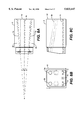
- a first refractory block component 5 of a burner assembly embodiment of the invention is illustrated in FIG. 1, having three fuel fluid cavities 1a, 1b, and 1c in a first plane 2, and two oxidant fluid cavities 3a and 3b in the second plane 4.
- the two first and second planes (2 and 4) make an angle ⁇ .
- the three fuel fluid cavities 1a, 1b, and 1c make an angle ⁇ between two adjacent ones, preferably the same.
- the axis of the middle fuel cavity 1b is perpendicular to an exit face 10 of refractory block 5.
- FIG. 2 illustrates a front view of block 5 of FIG. 1.
- d represents the diameter of fuel cavities 1a, 1b, and 1c at exit face 10;
- l represents their respective axial separation distance at exit face 10;
- D represents the diameter of oxidant cavities 3a and 3b at exit face 10;
- L their respective axial separation distance at exit face 10.
- "h” represents the distance between planes 2 and 4 at exit face 10 of block 5. It is to be recognized that all dimensions described herein with reference to FIG. 2 may be modified based on the particular fuel used. For example, if fuel oil is used, the distance h would tend to be greater than if natural gas were used as the fuel.
- FIG. 3 represents a schematic side elevation view of the operation of the combustion system of FIGS. 1 and 2 as used in, for example, a glass melting tank 12, while FIG. 4 illustrates a perspective view of the system of FIGS. 1-3.
- a fuel "sheet” or “cloud” is formed by fuel fluid streams exiting the fuel cavities in the first plane 2. Jets of oxidant 6 exit the cavities of the second plane 4, and intersect the fuel sheet in the combustion chamber 70 of the furnace. Combustion of the fuel with the oxidant occurs at an interface between the two flows to generate a flame 8 above the melt 9.
- the region located under the flame is fuel rich, which promotes the formation of carbon particles (soot) and thus enhances the luminosity of the flame.
- FIGS. 1 to 3 The configuration illustrated in FIGS. 1 to 3 was tested in a pilot scale furnace of square cross section (1 m wide and 2.5 meters long).
- the furnace was heated up to 820° C. (1500° F.) by an assist oxygen natural gas burner.
- the combustion system of the invention was started and the assist burner shut down.
- the flame was viewed from the side of the furnace which had viewing ports.
- the burner assembly including the refractory block illustrated in FIG. 1 was rotated (e.g. by 90 degrees), so that the flame could be better monitored from the side viewports.
- the first plane of the natural gas cavities was parallel to one of the furnace walls (side or bottom).
- the combustion system that was tested used natural gas flowing at about 32 nm 3 /hr (1200 scfh) as a fuel fluid and pure oxygen flowing at about 64 nm 3 /hr (2400 scfh) as the oxidant fluid under a pressure of about 100 m bar above the furnace pressure. This represents a combustion ratio of about 1.
- the distance L between the oxygen cavities was 15 cm.
- the angle between the natural gas cavities was 5 degrees.
- the arrangement allowed to vary the distance h between the first plane and the second plane from 2.5 cm to 10 cm, and the relative angle of the two oxygen cavities from 0 to 5 degrees.
- the cavities included injectors made of ceramic mullite tubes (stainless steel tubes have been further tested too).
- All cavities were mounted in cavities drilled through refractory material (referred to as the refractory block 5).
- the diameter of the natural gas cavities was varied between 0.925 cm and 1.58 cm (0.364 inches and 0.622 inches) so that fuel fluid velocities of 44 m/s, 26 m/s, and 16 m/s, were respectively achieved.
- the diameter of the oxygen cavities was varied between 1.9 and 2.66 cm (0.75 and 1.049 inches) so that oxygen velocities of 16 m/s, 27 m/s, and 31 m/s were achieved.
- the CO, O 2 , CO 2 , NO x contents in the flue gases were continuously monitored.
- the average furnace temperature was about 1450° C. for all the tests.
- a sampling probe was also introduced in the furnace, at a distance of two meters from the block 5 to measure the local CO concentration in the flame. Low measured CO concentrations at the sampling probe indicate short flames. Another indication of short flames for this particular furnace is the observation of relatively low temperature flue gases, with about the same stoichiometric conditions.
- the flame stability could be significantly improved without affecting the flame luminosity and the flame length if one natural gas injector is located in between the two oxygen cavities of the second plane, such as indicated on FIG. 5, preferably if one of the natural gas injector 21 in the first plane 2 is moved to the second plane 4, or close to it, substantially at the same distance from each oxygen injector 23, 24.
- the other two fuel cavities 20, 22 keep the same position.
- a combustion system according to the invention can thus be used to increase the heat transfer toward the load and reduce the furnace crown temperature.
- an equivalent improvement of the flame stability can be obtained if an auxiliary oxygen injector 25 is installed in the first plane 2 of the fuel cavities 20, 22, as shown for example on FIG. 6. (The same relative locations of this oxygen injector and the gas cavities applies, as disclosed on FIG. 5.) In this configuration, there are two oxygen cavities 23, 24 in the second plane 4 and two fuel cavities 20, 22 and one oxygen injector 25 in the first fuel plane 2.
- the flame length can be varied by changing the angle a between the second plane 4 of the oxygen cavities and the first fuel plane 2 of the fuel cavities.
- the flame stability is enhanced and maintained over the range of flame length adjustment by an auxiliary injection of fuel near the oxygen cavities, or an auxiliary injection of oxygen near the fuel cavities.
- Changing the angle between the two flames can also be used to increase the heat transfer towards the load of the furnace, and thus improve the efficiency of the fuel burnt.
- additional heat transfer in some areas of furnaces can be useful to enhance the convective circulations of the molten glass and/or increase the residence time of the molten glass in the furnace, which improves the glass quality.
- Combustion systems of the present invention are intended to be used, for example, to replace air-fuel combustion systems in already existing furnaces, and/or to be used as the main source of energy in new furnaces.
- a burner having oxidant exits which are slightly angled to the sides, and generally contoured, preferably rounded, at their tips (i.e. at the exit face 10). Quite surprisingly, it has been discovered that the angled exits allow the oxygen flow and, thus, the flame to be wider and prevent fuel from exiting unburned. Additionally, the rounded tips cause less turbulence, and, hence, afford a greater control over flame shape.
- the principal components of a preferred burner assembly depicted in FIG. 7 are: 1) a refractory block 5; 2) a mounting bracket assembly 72; 3) a fuel distributor 74, located at the bottom of the mounting bracket assembly, and 4) an oxidant distributor 76, located at the top of the mounting bracket assembly. Fuel is supplied through an inlet 78. Oxidant is supplied to the burner assembly through an inlet 80.
- FIGS. 8a plan view
- 8b end elevation
- 8c side elevation
- the fuel and oxidant cavities are straight holes through refractory block 5.
- the gas exit of each oxidant cavity and each fuel cavity have rounded edges at the gas exit face 10 as opposed to straight edges.
- the rounded edges reduce the velocity gradient between the gas flows ejected from the block and the surrounding atmosphere, which prevents particulates or volatile species contained in the atmosphere to build-up around the outlets of the cavities which in turn would alter the geometry of the cavities. This is particularly important in the case of the natural gas cavities, because the build-up process can be aggravated by the thermal cracking of the natural gas and the formation of coke deposits at the natural gas exits from the refractory blocks, which can alter flow direction in the furnace.
- the bottom cavities used for the fuel make a diverging angle ⁇ in order to distribute the fuel gas flow in a sheet pattern.
- the refractory block 5 illustrated in FIGS. 9a (side elevation) and 9b (plan view) has five cavities: three cavities at the bottom for the injection of fuel in the furnace, and two cavities at the top for the oxidant injection.
- the refractory block 5 depicted in FIGS. 9a and 9b is preferably a single piece of refractory material having multiple cavities or through holes therethrough, such as cavities 91 and 92 for oxidant, and cavities 94, 96, and 98 for fuel.
- cavities 91 and 92 for oxidant such as cavities 91 and 92 for oxidant
- cavities 94, 96, and 98 for fuel.
- oxidant cavities 91 and 92 are initially parallel to each other and with the fuel cavities (see portions 91a and 92a), but then angle away from each other at an angle of 2 ⁇ , and toward the fuel cavities at an angle ⁇ .
- fuel cavities 94 and 98 (the two on either side of the block 5) angle away from the central fuel cavity 96 at an angle, preferably also ⁇ . This design allows the ability to position the exits of the fuel cavities closer to one another than in the embodiment illustrated in FIG. 8. Closer fuel exits might be useful when the fuel is fuel oil.
- Suitable materials for the refractory block are fused zirconia (ZrO 2 ), fused cast AZS (alumina-zirconia-silica) rebonded AZS, or fused cast alumina (Al 2 O 3 ).
- ZrO 2 fused zirconia
- fused cast AZS alumina-zirconia-silica rebonded AZS
- fused cast alumina Al 2 O 3
- FIGS. 10a plan view illustrating oxidant cavities only
- 10b plan view illustrating fuel and oxidant cavities
- 10c back end elevation
- 10d side elevation
- Each of the oxidant cavities 91 and 92 comprise two straight flow paths 91a and 92a, initially parallel, that make a small outward angle near the exit (flow paths). The purpose of the small angle is to direct the flow of oxidant outwards, in a similar fashion as the jets of fuel gas.
- angling out the oxidant (in the tests oxygen was used) cavities proved to give more stability to the flame and is beneficial to the burner operation by widening flame width without significantly decreasing flame length.
- a preferred configuration is when the angle between the two oxidant cavities at their exits is equal to the angle between the two side fuel gas cavities.
- FIGS. 11a-e is similar to the embodiment illustrated in FIG. 10, except that FIG. 11e illustrates that the two side fuel injectors make a small angle outward near their exit; thus both of the oxidant cavities 91b and 92b veer outward near exit face 10, as well as the two side fuel injectors 94b and 98b.
- the oxygen cavities are preferably angled downward toward the natural gas cavities.
- the angle shown on the drawings is 10 degrees. Under certain conditions, a smaller angle (such as 7.5 degrees) can be used. Again angling out the last few inches of the cavities is enough to impart a converging angle between the oxygen jets and the natural jets.
- the burner assembly illustrated in FIG. 12 includes a mounting bracket made of two parts that are positioned on each of the upper and lower portions of refractory block 5, fastened together by bolts 32 screwed in plate P.
- the mounting bracket assembly slides in vertical grooves G 1 and G 2 in the refractory block, and is thus well anchored to the block once the bolts 60 and 61 are in place.
- An oxidant distributor 30 of FIG. 12 is mounted directly on the mounting bracket assembly with bolts 32 and plate 34. Tightness between the distributor and the block is insured by a gasket 36.
- the distributor comprises a plate 38 on which oxidant injectors 40 and 41 are welded. When mounted on the burner, the oxidant injectors penetrate into cavities in burner block 5, and stop about 10 cm (4 inches) away from exit face 10 of the block, before any change in direction of the flow that can be imparted by the geometry of the oxidant cavities.
- a fuel gas distributor 50 is mounted on a plate 52 with quick connect clamps 53a and 53b.
- Plate 52 is attached to the mounting bracket by bolts 54a and 54b.
- Tightness between plate 52 and refractory block 5 is insured by a gasket 56.
- Three gas injectors 58a, 58b, and 58c penetrate into refractory block 5, and stop about 10 cm (4 inches) away from exit face 10 of block 5 before any change in direction of the flow that can be imparted by the geometry of the fuel gas cavities.
- the inlet heads of the fuel gas injectors are imprisoned between the injector 60 and plate 52.
- Fuel gas injector tightness is insured by O-rings 62 and 64 positioned on the inlet head of the fuel gas injectors.
- the tube sealing detail in FIG. 12(d) is noted, in particular.
- FIG. 13a is a perspective view of a refractory block 5 useful in the invention, illustrating the exits of two oxidant cavities 91a and 91b, the exits of three fuel gas cavities 94a, 94b, and 94c, and the exit of one liquid fuel cavity 95.
- FIG. 13b is a gas exit end elevation view of the refractory block of FIG. 13b, illustrating distances d 1 and d 2 , wherein d 2 is the distance between a plane containing the axial center of the two oxidant cavities 91 (second plane) and the liquid fuel cavity 95, and d 1 is the distance between the second plane and a plane containing the three fuel gas cavities 94. (Note that d 1 is the same distance as h in FIG.
- FIG. 13c is a gas exit end elevation view of an alternate design for the refractory block of FIG. 13a, illustrating an embodiment wherein there are in fact no gaseous fuel exits, and only one liquid fuel exit 97 is present (the two oxidant gas exits are the same as in FIG. 13a).
- P is the burner capacity in kilowatts (kW), and about 500 mm ⁇ A ⁇ about 150 mm.
- the preferred value for A is about 110 mm.
- I FO liquid fuel momentum in the cavity or injector
- I AIR atomizing air momentum in the injector or cavity
- ⁇ NG gaseous fuel specific gravity
- FIG. 14 is a side elevation view of a burner assembly without a refractory block, having only oxidant injectors 102 and fuel injectors 104 inserted through and secured in a wall 100 of a furnace or glass melt tank, in accordance with another burner assembly embodiment of the present invention.
- the oxidant injectors are illustrated as being straight, with no change in angle, but of course the injectors may initially be parallel with the fuel injectors, and then change direction, so that the fuel and oxidant mix in the combustion chamber.
- This embodiment may also be used when the fuel is a liquid fuel.
- This arrangement, as well as the embodiment illustrated in FIG. 17, may be useful in that the fuel and oxidant may be preheated by combusted fuel in the combustion chamber, adding to the efficiency of fuel combustion.
- FIG. 15 is a plan view of a refractory block, illustrating cavities (oxidant or fuel) 91a and 91b;
- FIG. 16 is a plan view of the refractory block of FIG. 15, illustrating an embodiment having short injectors 102a and 102b inside the cavities;
- FIG. 17 is a plan view of the refractory block of FIG. 15, illustrating an embodiment having long injectors 102a and 102b protruding outside of the cavities.
- FIG. 18 is a sectional view of a liquid fuel atomizer 200 useful in the invention.
- the present aspect of the invention falls within the scope of the third mode of liquid fuel atomization; it describes a complete device that makes possible control of the atomization of a liquid fuel using a gaseous fluid and the application of this device to a burner, such as the inventive burner assemblies described herein.
- the fluid introduction into the combustion zone is a two-phase mixture of atomizing gas and droplets of liquid fuel.
- specific characteristics of the invention reside in the fact that atomization takes place outside of the nozzle (external atomization) and yet permits forming distinct spray jets having high relative angles (5° to 30°).
- the inventive liquid fuel atomizer is capable of ensuring the production of a single broad flame, a single long flame, or several short flames simultaneously.
- the atomization principle adopted in the atomizer of the present invention is external atomization. This choice was essentially imposed by the constraints of thermal resistance and maintenance of the injector when used in a third generation burner (self-cooled burner with separate injection). In effect, the temperature levels potentially reached by the fuel injectors in burners of this type are very much higher than those previously encountered with first and second generation burners.
- the liquid fuel is constantly "sheathed" by the atomizing fluid, which, being heated preferentially, draws off the heat flux transmitted to the injector.
- the atomizing fluid thus protects the liquid fuel from any excessive heating that could produce the beginnings of coke formation.
- the liquid fuel atomizer of the present invention comprises:
- this outer nozzle is composed of two symmetrical cowls which, when they are positioned face to face, form channels for flow of atomization fluid, as further explained in part IIB.
- the liquid fuel atomizer 200 is composed of a first hollow cylinder 202 having an internal surface 204 of inside diameter D OI , and an outside surface 206 having outside diameter D OE .
- Hollow cylinder 202 has a fuel exit end 203 having a single fuel exit fluidly connected to a plurality of hollow elementary conduits C 1 , C 2 , and C 3 .
- Liquid fuel is delivered into first hollow cylinder 202 having diameter D OI and then to the interior of all the hollow elementary conduits to emerge from an atomized fuel exit end 208 of the liquid fuel atomizer 200 (combustion chamber side).
- the number of hollow elementary conduits C can range from 2 to 5 (typically 2 or 3).
- the axes of all the hollow elementary conduits C are in the same plane ("spray plane"); this plane contains the axis of the first hollow cylinder 202.
- Each of the hollow elementary conduits C will have an inside diameter D i 1 (into which the liquid fuel will flow) and an outside “diameter" D i 2 .
- the external shape of the hollow elementary conduits C is not necessarily cylindrical: it can be parallelepipedal with square section. In such a case, D i 2 is the side of the square, the side parallel to the "spray plane.”
- Each of these hollow elementary conduits C has an inclination angle ⁇ i 1 , with respect to the axis of the cylinder (D OI ; D OE ); this angle is in the "spray plane.”
- each of these hollow elementary conduits C (distance between the first hollow cylinder 202 and the end of the hollow elementary conduit) is L i 1 .
- the outer nozzle 210 is formed of a second hollow cylinder 212 (having an inside surface 214 of diameter D FI , and an external surface 216 of outside diameter D FE ) which is extended by a profiled part 218 comprised of two symmetrical cowls 219 and 221.
- the interior of profiled part 218 of nozzle 210 is pierced by channels 220, 222, 224 which merge with the second hollow cylinder 212.
- the number of channels 220, 222, 224 is equal to the number of hollow elementary conduits C present in outer nozzle 210. All the axes of these channels 220, 222, 224 are located in the "spray plane", denoted by solid line eff which also contains the axis of second hollow cylinder 212.
- Solid line e ff denotes the separation between symmetrical cowls 219 and 221.
- the channels 220, 222, 224 have a length L i 2 and a diameter D i 3 .
- the shape of the channels is the same as that of the elementary conduits of the fuel injector: it can be cylindrical or parallelepipedal with square section (in the former case, D i 3 is the diameter of the cylinder; in the latter case D i 3 is the length of the side of the square, the side parallel to the "spray plane").
- Each of channels 220, 222, 224 has an inclination angle ⁇ i 2 with respect to the axis of the second hollow cylinder 212; this angle is in the "spray plane.”
- first hollow cylinder 202 coincides with that of second hollow cylinder 212.
- the atomizing fluid is delivered through second hollow cylinder 212, between surfaces 206 and 214, and then to the interior of the outer nozzle 210 and through channels 220, 222, and 224, and to exit end 208.
- An elementary atomizer is comprised of
- a hollow elementary conduit C 3 inside which the liquid fuel flows.
- the outside surface 226 of a hollow elementary conduit C 3 can be cylindrical or parallelepipedal with square section; the internal geometry of the hollow elementary conduit C 3 is cylindrical.
- a machined channel 224 in which hollow elementary conduit C 3 is arranged.
- the geometry of this channel 224 is the same as the external geometry of hollow elementary conduit C 3 .
- the atomizing fluid circulates in channel 224, around hollow elementary conduit C 3 .
- all the elementary atomizers composing the atomization device 200 of the invention conform to precise technical criteria.
- the thickness of the hollow elementary conduit C must be as small as possible in order to permit immediate shearing of the jet of liquid fuel as it exits from the hollow elementary conduit C by the atomizing fluid which flows along its periphery: the smaller the thickness of material separating the fuel from the atomizing fluid is, the more rapidly the two fluids will be brought in contact and thus the more effective the shearing between the two jets will be. Furthermore, a reduction in the thickness of the conduit also favors the formation of a spray having a low solid angle.
- a decrease in this thickness also serves to decrease the amount of material subjected to the thermal radiation from the combustion chamber: the smaller the thickness of the conduit is, the more limited the amount of heat captured by the conduit will be. The temperature of the conduit will be lowered as a consequence.
- this thickness must be sufficient to provide mechanical resistance to the shocks that occur during manipulation of the atomization device.
- V atomizing fluid V atomizing fluid
- each of the elementary atomizers is to eject a spray of droplets in a precise direction. This direction is the direction of the axis of channel 224 and hollow elementary conduit C 3 for liquid fuel.
- the Length of the hollow elementary conduit and the length of its respective channel must be sufficient to secure establishment of the flows of the two fluids in their respective conduits. If one wishes that the two fluids enter the combustion chamber with the same orientation of the axial components of their respective velocity vectors, it is preferred that:
- the criterion to be satisfied is:
- Letting i and j be two elementary atomizers, L i 1 L j 1 .
- D i 1 values specific to each of the hollow elementary conduits C.
- D i 1 the more fuel will be carried by hollow elementary atomizer i.
- the criterion to be satisfied is:
- Letting i and j be two elementary atomizers, L i 2 L j 2 .
- the relative angle between the different elementary atomizers is a function of the number of elementary atomizers composing the atomization device and the flame morphology one wishes to obtain.
- Length of visible flame 3.5 m.
- Width of visible flame 1.5 m.
- Length of visible flame 4.5 m.
- Width of visible flame 0.7 m.
- Length of 3 separate visible flames 1.5 m.
- Width of 3 separate visible flames 0.5 m.
- the liquid fuel atomizer of the invention In the case of continuous use of the inventive liquid fuel atomizer 200 in glass furnaces (combustion chambers with elevated temperatures ranging from 1500° C. to 1670° C.) the liquid fuel atomizer of the invention must be capable of ensuring production of a stable flame for periods on the order of months.
- the atomization principle selected makes it possible to keep the temperature of the metal parts composing the device below 1100° C. Thus, the temperature measured at the tip of the device during an industrial test for one month in a glass furnace at 1600° C. never exceeded 800° C.
- outer nozzle 210 To avoid the formation of a layer of glass condensates on the outside of outer nozzle 210, two symmetrical orifices 230, 232 are provided in the outer nozzle 210 (FIG. 19a and FIG. 19b) generally vertically aligned in a plane designated 240.
- the diameter D OR and the elevation H OR are established in such a way that the jet of atomizing fluid emerging from the orifices 230, 232 covers the entire surface of the exit end 208 of the outer nozzle 210.
- the liquid fuel atomizer 200 of the present invention it is possible to significantly vary the length of the flame (or flames) produced by a burner using this device.
- the flexibility (in terms of flame length at constant fuel delivery rate) observed when the liquid fuel atomizer 200 is deployed in a glass furnace corresponds to a ratio of one to three (flame length varying from about 3.7 to about 1.2 m).
- This control of the flame length is achieved by increasing or decreasing the delivery rate of the atomizing fluid flowing between the outer nozzle 210 and the hollow elementary conduits C. This variation in delivery rate is directly linked to the variation in pressure of the atomizing fluid upstream from the liquid fuel atomizer 200.
- the liquid fuel atomizer 200 functions at an atomizing fluid pressure between about 1 and 6 bars relative.
- This phenomenon is directly attributable to the change in the particle size distribution of the droplets of liquid fuel composing the spray that is formed: the increase in the rate of delivery of atomizing fluid has the effect of decreasing the average spray droplet diameter and narrowing the distribution of the diameters about this mean value. Conversely, a decrease in the rate of delivery of atomizing fluid will increase the average diameter while widening the distribution.
- the overall mechanism of combustion of a liquid fuel reveals three characteristic times which, according to their respective weights, completely determine the type of flame resulting from a given atomization. These three characteristic times are: the evaporation time, the chemical time, and the hydrodynamic time. Obtaining a particle size distribution confined narrowly about small drop diameters leads to a decreased time for vaporization of the droplets and thus an increased rapidity of deflagration since the chemical time remains nearly constant. A spray characterized by such a distribution (high atomizing fluid delivery rate) will thus produce a short flame typical of a rapid combustion and very localized in space.
- Preferred pressurized atomization fluids are employed, such as pressurized air, steam, water vapor, and the like.
- FIG. 20a is a schematic illustration of a refractory block 5 and fuel gas cavity 94 in same, while FIG. 20b is a schematic illustrating a cavity throat diameter D' and gas a exit diameter D for an injector or cavity.
- the ratio of 1 (from FIG. 2, the distance between adjacent fuel gas exits) and D' (fuel cavity or injector throat diameter) ranges from about 1.5 to about 10, more preferably from about 1.5 to about 3, and most preferably about 2.
- FIG. 20a also illustrates that the cavities in the refractory block may have varying diameter in the direction of gas flow, and that the gas exits are generally contoured at the exits, allowing the exits to be less likely to be plugged.
- FIGS. 21 and 22 are gas exit end elevation views of two other refractory block embodiments within the invention, illustrating oxidant cavities 91a and 91b.
- the embodiment of FIG. 21 illustrates that the fuel gas cavities 94 may have concentric gas injectors in each cavity, whereby for example, fuel may injected in small diameter fuel gas injector 94' for low power operation, and through either the large diameter fuel gas injector 94 only, or through both injectors 94 and 94' for high power burner operation. Control of fuel flow between 94 and 94' may be controlled by suitable valving arrangements, or through the use of an orifice in the line feeding one or the other of 94 and 94'.
- a liquid fuel injector 95 is also illustrated.
- FIG. 22 illustrates a very important alternative refractory block embodiment within the invention, wherein it has been discovered that flame stability is significantly increased when the peripheral oxidant injectors 91a and 91b, when positioned as illustrated, have a distance separating them of L, is greater than two times the distance l between adjacent fuel injectors, that is when L>21. This is true also when the fuel and oxidant are injected via the use only of injectors, rather than the use of a refractory block.
- FIGS. 23-31 illustrate, in front elevation views, other embodiments of burner assemblies of the invention.
- FIG. 23 illustrates an embodiment wherein the two oxidant cavities 91a and 91b have exits which are rectangular, also illustrating three fuel gas exits 94 and a liquid fuel exit 95.
- FIG. 24 illustrates an embodiment wherein oxidant emanates from two oxidant exits 91a and 91b, and oxidant also emanates from three annular portions 91' which surround respectively three fuel exits 94'.
- FIG. 25 illustrates an embodiment wherein a single oxidant exit 91 is present as a rectangle having a width much greater than its height.
- the ratio of width to height of the oxidant cavity exit may range from 1:1 up to about 4:1.
- FIG. 26 illustrates an embodiment wherein the two oxidant cavities 91a and 91b have exits which are ellipsoid, also illustrating three fuel gas exits 94.
- FIG. 27 illustrates an embodiment similar to the embodiment of FIG. 26, with the addition of a liquid fuel cavity 95 having a circular exit.
- FIG. 28 illustrates an embodiment wherein a single ellipsoid oxidant exit 91 is present with three fuel gas cavities 94 having circular exits.
- FIG. 29 illustrates an embodiment similar to the embodiment of FIG. 28, with the addition of a liquid fuel cavity 95 having a circular exit.
- FIG. 30 illustrates an embodiment wherein a single ellipsoid oxidant exit 91 is present with two fuel gas cavities 94 having circular exits.
- FIG. 31 illustrates an embodiment similar to the embodiment of FIG. 30 wherein a single ellipsoid oxidant exit 91 is present with two fuel gas cavities 94 having circular exits, with the addition of a liquid fuel cavity 95 having a circular exit.
- FIGS. 32 and 33 illustrate embodiments wherein oxidant emanates from one or more positions both above and below the fuel exit(s).
- the fuel cavities are essentially parallel to the lower oxidant cavities, while the upper oxidant cavities are angled down so that the upper oxidant fluid flow converges with the fuel fluid flow and the lower oxidant fluid flows in the combustion chamber.
- duel oxidant exits 91a and 91b are positioned above and below, respectively, of a single fuel exit 94.
- FIG. 33 illustrates a similar embodiment, except that there are two oxidant exits 91a and 91b above two fuel exits 94, and two oxidant exits 91a' and 91b' below the duel fuel exits. More than two fuel exits, with corresponding upper and lower oxidant exits, can be envisioned.
- exits of oxidant and fuel in all embodiments are preferably contoured, as depicted for example in FIGS. 8-11.
Landscapes
- Engineering & Computer Science (AREA)
- Chemical & Material Sciences (AREA)
- Combustion & Propulsion (AREA)
- Mechanical Engineering (AREA)
- General Engineering & Computer Science (AREA)
- Materials Engineering (AREA)
- Organic Chemistry (AREA)
- Combustion Of Fluid Fuel (AREA)
- Pre-Mixing And Non-Premixing Gas Burner (AREA)
- Air Supply (AREA)
- Nozzles For Spraying Of Liquid Fuel (AREA)
Priority Applications (1)
| Application Number | Priority Date | Filing Date | Title |
|---|---|---|---|
| US08/714,743 US5833447A (en) | 1995-07-17 | 1996-09-13 | Combustion process and apparatus therefore containing separate injection of fuel and oxidant streams |
Applications Claiming Priority (3)
| Application Number | Priority Date | Filing Date | Title |
|---|---|---|---|
| US50333695A | 1995-07-17 | 1995-07-17 | |
| US08/668,758 US5984667A (en) | 1995-07-17 | 1996-06-24 | Combustion process and apparatus therefore containing separate injection of fuel and oxidant streams |
| US08/714,743 US5833447A (en) | 1995-07-17 | 1996-09-13 | Combustion process and apparatus therefore containing separate injection of fuel and oxidant streams |
Related Parent Applications (1)
| Application Number | Title | Priority Date | Filing Date |
|---|---|---|---|
| US08/668,758 Continuation US5984667A (en) | 1995-07-17 | 1996-06-24 | Combustion process and apparatus therefore containing separate injection of fuel and oxidant streams |
Publications (1)
| Publication Number | Publication Date |
|---|---|
| US5833447A true US5833447A (en) | 1998-11-10 |
Family
ID=27054469
Family Applications (2)
| Application Number | Title | Priority Date | Filing Date |
|---|---|---|---|
| US08/714,743 Expired - Lifetime US5833447A (en) | 1995-07-17 | 1996-09-13 | Combustion process and apparatus therefore containing separate injection of fuel and oxidant streams |
| US09/093,495 Expired - Lifetime US6068468A (en) | 1995-07-17 | 1998-06-08 | Refractory block for use in a burner assembly |
Family Applications After (1)
| Application Number | Title | Priority Date | Filing Date |
|---|---|---|---|
| US09/093,495 Expired - Lifetime US6068468A (en) | 1995-07-17 | 1998-06-08 | Refractory block for use in a burner assembly |
Country Status (7)
| Country | Link |
|---|---|
| US (2) | US5833447A (zh) |
| EP (1) | EP0754912B1 (zh) |
| JP (2) | JP3989984B2 (zh) |
| CN (1) | CN1195172C (zh) |
| CA (1) | CA2181292C (zh) |
| DE (1) | DE69632666T2 (zh) |
| ES (1) | ES2220965T3 (zh) |
Cited By (69)
| Publication number | Priority date | Publication date | Assignee | Title |
|---|---|---|---|---|
| EP0967440A2 (en) | 1998-06-25 | 1999-12-29 | L'air Liquide, Societe Anonyme Pour L'etude Et L'exploitation Des Procedes Georges Claude | Optical monitoring and control system for oil combustion |
| US6068468A (en) * | 1995-07-17 | 2000-05-30 | American Air Liquide, Inc. | Refractory block for use in a burner assembly |
| US6074197A (en) * | 1996-11-25 | 2000-06-13 | American Air Liquide, Inc. | Combustion process and apparatus therefore containing separate injection of fuel and oxidant streams |
| US6113389A (en) * | 1999-06-01 | 2000-09-05 | American Air Liquide, Inc. | Method and system for increasing the efficiency and productivity of a high temperature furnace |
| US6132204A (en) * | 1998-06-30 | 2000-10-17 | Praxair Technology, Inc. | Wide flame burner |
| US6196831B1 (en) * | 1998-09-02 | 2001-03-06 | L'air Liquide, Societe Anonyme Pour L'etude Et L'exploitation Des Procedes Georges Claude | Combustion process for burning a fuel |
| US6461151B1 (en) * | 1999-03-31 | 2002-10-08 | Alstom (Switzerland) Ltd | Burner for a heat generator |
| US6524097B2 (en) * | 1999-10-18 | 2003-02-25 | Air Products And Chemicals, Inc. | Method and apparatus for backing-up oxy-fuel combustion with air-fuel combustion |
| US6540508B1 (en) | 2000-09-18 | 2003-04-01 | The Boc Group, Inc. | Process of installing roof mounted oxygen-fuel burners in a glass melting furnace |
| US6705117B2 (en) | 1999-08-16 | 2004-03-16 | The Boc Group, Inc. | Method of heating a glass melting furnace using a roof mounted, staged combustion oxygen-fuel burner |
| US6926516B1 (en) | 1999-08-17 | 2005-08-09 | Nippon Furnace Kogyo Kabushiki Kiasha | Combustion method and burner |
| US20070037106A1 (en) * | 2005-08-12 | 2007-02-15 | Kobayashi William T | Method and apparatus to promote non-stationary flame |
| US20070141522A1 (en) * | 2005-12-21 | 2007-06-21 | Borders Harley A | Burner apparatus and methods for making inorganic fibers |
| US20070172780A1 (en) * | 2004-09-15 | 2007-07-26 | Aga Ab | Method pertaining to combustion, and a burner |
| US20070281264A1 (en) * | 2006-06-05 | 2007-12-06 | Neil Simpson | Non-centric oxy-fuel burner for glass melting systems |
| WO2008003909A2 (fr) * | 2006-07-06 | 2008-01-10 | L'air Liquide Societe Anonyme Pour L'etude Et L'exploitation Des Procedes Georges Claude | Procédé de chauffage d'une charge |
| US20080020334A1 (en) * | 2004-07-01 | 2008-01-24 | Air Products And Chemicals, Inc. | Staged Combustion System With Ignition-Assisted Fuel Lances |
| US20090148797A1 (en) * | 2005-10-24 | 2009-06-11 | L'air Liquide Societe Anonyme Pour L'etude Et Exloitation Des Procedes Georges Claude | Method for Carrying Out combined Burning in a Recovering Furnace |
| US20100050912A1 (en) * | 2006-12-22 | 2010-03-04 | Khd Humboldt Wedag Gmbh | Method for controlling the operation of a rotary furnace burner |
| US20100159409A1 (en) * | 2006-06-05 | 2010-06-24 | Richardson Andrew P | Non-centric oxy-fuel burner for glass melting systems |
| US20100183990A1 (en) * | 2009-01-16 | 2010-07-22 | Air Products And Chemicals, Inc. | Multi-Mode Combustion Device and Method for Using the Device |
| US7802452B2 (en) | 2005-12-21 | 2010-09-28 | Johns Manville | Processes for making inorganic fibers |
| US20110154950A1 (en) * | 2009-07-06 | 2011-06-30 | Air Products And Chemicals, Inc. | Burner and Method for Processing Oxidizable Materials |
| EP2375482A1 (en) * | 2010-04-12 | 2011-10-12 | Samsung SDI Co., Ltd. | Nozzle assembly and fuel reforming apparatus |
| WO2013052086A2 (en) * | 2011-10-03 | 2013-04-11 | Saint-Gobain Containers, Inc. | Reduced emissions combustor |
| US8707740B2 (en) | 2011-10-07 | 2014-04-29 | Johns Manville | Submerged combustion glass manufacturing systems and methods |
| EP2743623A1 (en) * | 2012-12-11 | 2014-06-18 | Linde Aktiengesellschaft | Furnace and method for heating an atmosphere in a combustion chamber of a furnace |
| US8875544B2 (en) | 2011-10-07 | 2014-11-04 | Johns Manville | Burner apparatus, submerged combustion melters including the burner, and methods of use |
| US8973405B2 (en) | 2010-06-17 | 2015-03-10 | Johns Manville | Apparatus, systems and methods for reducing foaming downstream of a submerged combustion melter producing molten glass |
| US8973400B2 (en) | 2010-06-17 | 2015-03-10 | Johns Manville | Methods of using a submerged combustion melter to produce glass products |
| US8991215B2 (en) | 2010-06-17 | 2015-03-31 | Johns Manville | Methods and systems for controlling bubble size and bubble decay rate in foamed glass produced by a submerged combustion melter |
| US8997525B2 (en) | 2010-06-17 | 2015-04-07 | Johns Manville | Systems and methods for making foamed glass using submerged combustion |
| US9021838B2 (en) | 2010-06-17 | 2015-05-05 | Johns Manville | Systems and methods for glass manufacturing |
| US9096452B2 (en) | 2010-06-17 | 2015-08-04 | Johns Manville | Methods and systems for destabilizing foam in equipment downstream of a submerged combustion melter |
| US9492831B2 (en) | 2010-06-17 | 2016-11-15 | Johns Manville | Methods and systems for destabilizing foam in equipment downstream of a submerged combustion melter |
| US9533905B2 (en) | 2012-10-03 | 2017-01-03 | Johns Manville | Submerged combustion melters having an extended treatment zone and methods of producing molten glass |
| US9676644B2 (en) | 2012-11-29 | 2017-06-13 | Johns Manville | Methods and systems for making well-fined glass using submerged combustion |
| USRE46462E1 (en) | 2011-10-07 | 2017-07-04 | Johns Manville | Apparatus, systems and methods for conditioning molten glass |
| US9731990B2 (en) | 2013-05-30 | 2017-08-15 | Johns Manville | Submerged combustion glass melting systems and methods of use |
| US9751792B2 (en) | 2015-08-12 | 2017-09-05 | Johns Manville | Post-manufacturing processes for submerged combustion burner |
| US9777922B2 (en) | 2013-05-22 | 2017-10-03 | Johns Mansville | Submerged combustion burners and melters, and methods of use |
| US9776903B2 (en) | 2010-06-17 | 2017-10-03 | Johns Manville | Apparatus, systems and methods for processing molten glass |
| US9815726B2 (en) | 2015-09-03 | 2017-11-14 | Johns Manville | Apparatus, systems, and methods for pre-heating feedstock to a melter using melter exhaust |
| US9926219B2 (en) | 2012-07-03 | 2018-03-27 | Johns Manville | Process of using a submerged combustion melter to produce hollow glass fiber or solid glass fiber having entrained bubbles, and burners and systems to make such fibers |
| US9982884B2 (en) | 2015-09-15 | 2018-05-29 | Johns Manville | Methods of melting feedstock using a submerged combustion melter |
| USRE46896E1 (en) | 2010-09-23 | 2018-06-19 | Johns Manville | Methods and apparatus for recycling glass products using submerged combustion |
| US10041666B2 (en) | 2015-08-27 | 2018-08-07 | Johns Manville | Burner panels including dry-tip burners, submerged combustion melters, and methods |
| US10081563B2 (en) | 2015-09-23 | 2018-09-25 | Johns Manville | Systems and methods for mechanically binding loose scrap |
| US10131563B2 (en) | 2013-05-22 | 2018-11-20 | Johns Manville | Submerged combustion burners |
| US10138151B2 (en) | 2013-05-22 | 2018-11-27 | Johns Manville | Submerged combustion burners and melters, and methods of use |
| US20180339927A1 (en) * | 2015-01-27 | 2018-11-29 | Knauf Insulation | Burner for submerged combustion melter |
| US10144666B2 (en) | 2015-10-20 | 2018-12-04 | Johns Manville | Processing organics and inorganics in a submerged combustion melter |
| US10183884B2 (en) | 2013-05-30 | 2019-01-22 | Johns Manville | Submerged combustion burners, submerged combustion glass melters including the burners, and methods of use |
| US10196294B2 (en) | 2016-09-07 | 2019-02-05 | Johns Manville | Submerged combustion melters, wall structures or panels of same, and methods of using same |
| US10233105B2 (en) | 2016-10-14 | 2019-03-19 | Johns Manville | Submerged combustion melters and methods of feeding particulate material into such melters |
| US10246362B2 (en) | 2016-06-22 | 2019-04-02 | Johns Manville | Effective discharge of exhaust from submerged combustion melters and methods |
| US10301208B2 (en) | 2016-08-25 | 2019-05-28 | Johns Manville | Continuous flow submerged combustion melter cooling wall panels, submerged combustion melters, and methods of using same |
| US10322960B2 (en) | 2010-06-17 | 2019-06-18 | Johns Manville | Controlling foam in apparatus downstream of a melter by adjustment of alkali oxide content in the melter |
| US10337732B2 (en) | 2016-08-25 | 2019-07-02 | Johns Manville | Consumable tip burners, submerged combustion melters including same, and methods |
| EP3453683A4 (en) * | 2016-08-19 | 2020-01-15 | Jushi Group Co., Ltd. | METHOD FOR HEATING A LIQUID GLASS CHANNEL OF A GLASS FIBER TUBE |
| US10654740B2 (en) | 2013-05-22 | 2020-05-19 | Johns Manville | Submerged combustion burners, melters, and methods of use |
| US10670261B2 (en) | 2015-08-27 | 2020-06-02 | Johns Manville | Burner panels, submerged combustion melters, and methods |
| US20200309366A1 (en) * | 2019-03-26 | 2020-10-01 | L'air Liquide, Societe Anonyme Pour L'etude Et L?Exploitation Des Procedes Georges Claude | Method and device for automatically adapting a flame to variable operating conditions |
| US10837705B2 (en) | 2015-09-16 | 2020-11-17 | Johns Manville | Change-out system for submerged combustion melting burner |
| US10858278B2 (en) | 2013-07-18 | 2020-12-08 | Johns Manville | Combustion burner |
| US11142476B2 (en) | 2013-05-22 | 2021-10-12 | Johns Manville | Burner for submerged combustion melting |
| US11161764B2 (en) * | 2017-07-21 | 2021-11-02 | Engie | Combustion method applied to melting materials such as glass in an end-fired furnace |
| US11613488B2 (en) | 2012-10-03 | 2023-03-28 | Johns Manville | Methods and systems for destabilizing foam in equipment downstream of a submerged combustion melter |
| EP4103880A4 (en) * | 2020-02-12 | 2024-01-10 | Selas Heat Tech Company Llc | OXYGEN FLAT BURNER AND BLOCK ARRANGEMENT |
Families Citing this family (38)
| Publication number | Priority date | Publication date | Assignee | Title |
|---|---|---|---|---|
| US6071116A (en) | 1997-04-15 | 2000-06-06 | American Air Liquide, Inc. | Heat recovery apparatus and methods of use |
| JP3522506B2 (ja) * | 1997-09-01 | 2004-04-26 | 東京瓦斯株式会社 | 酸素燃焼バーナと該バーナを持つ燃焼炉 |
| FR2777068B1 (fr) * | 1998-04-02 | 2000-05-05 | Air Liquide | Procede de combustion par injections separees du combustible et du comburant |
| JP3960444B2 (ja) * | 1998-08-28 | 2007-08-15 | 東京瓦斯株式会社 | 蓄熱燃焼装置 |
| JP3741883B2 (ja) * | 1998-11-20 | 2006-02-01 | 東京瓦斯株式会社 | 酸素燃焼バーナと該バーナを持つ燃焼炉 |
| JP3741884B2 (ja) * | 1998-11-27 | 2006-02-01 | 東京瓦斯株式会社 | 酸素燃焼バーナと該バーナを持つ燃焼炉 |
| US6126438A (en) * | 1999-06-23 | 2000-10-03 | American Air Liquide | Preheated fuel and oxidant combustion burner |
| US7168269B2 (en) | 1999-08-16 | 2007-01-30 | The Boc Group, Inc. | Gas injection for glass melting furnace to reduce refractory degradation |
| US6422041B1 (en) * | 1999-08-16 | 2002-07-23 | The Boc Group, Inc. | Method of boosting a glass melting furnace using a roof mounted oxygen-fuel burner |
| US6544029B2 (en) | 2000-09-27 | 2003-04-08 | L'air Liquide - Societe' Anonyme A Directoire Et Conseil De Surveillance Pour L'etude Et L'exploitation Des Procedes Georges Claude | Methods and apparatus for combustion in high volatiles environments |
| US6715319B2 (en) * | 2001-03-23 | 2004-04-06 | Pilkington Plc | Melting of glass |
| US7115226B2 (en) * | 2003-06-20 | 2006-10-03 | Mold-Masters Limited | Stack mold having a melt homogenizing element |
| ITMI20032327A1 (it) * | 2003-11-28 | 2005-05-29 | Techint Spa | Bruciatore a gas a basse emissioni inquinanti. |
| FR2863689B1 (fr) * | 2003-12-16 | 2006-05-05 | Air Liquide | Procede de combustion etagee mettant en oeuvre un oxydant prechauffe |
| US7500849B2 (en) * | 2004-01-16 | 2009-03-10 | Air Products And Chemicals, Inc. | Emulsion atomizer nozzle, and burner, and method for oxy-fuel burner applications |
| FR2879284B1 (fr) * | 2004-12-09 | 2007-01-19 | Air Liquide | Procede de fusion d'une composition de matieres premieres par un bruleur en voute |
| US20070231761A1 (en) * | 2006-04-03 | 2007-10-04 | Lee Rosen | Integration of oxy-fuel and air-fuel combustion |
| FR2917155A1 (fr) * | 2007-06-08 | 2008-12-12 | Saint Gobain Emballage Sa | Combustion diluee |
| US8454354B2 (en) * | 2008-05-08 | 2013-06-04 | Air Products And Chemicals, Inc. | Highly radiative burner and combustion process |
| EP2143999A1 (en) * | 2008-07-08 | 2010-01-13 | L'Air Liquide Société Anonyme pour l'Etude et l'Exploitation des Procédés Georges Claude | Burner assembly and method of combustion |
| CN102138040B (zh) * | 2008-08-29 | 2014-09-10 | 乔治洛德方法研究和开发液化空气有限公司 | 利用燃烧器组件产生燃烧的方法和所用的燃烧器组件 |
| US8172566B2 (en) * | 2010-02-18 | 2012-05-08 | Air Products And Chemicals, Inc. | Liquid fuel combustion process and apparatus |
| SE534084C2 (sv) * | 2010-05-04 | 2011-04-26 | Linde Ag | Förfarande för att öka värmehomogeniteten i en gropugn |
| TWI398613B (zh) * | 2010-07-01 | 2013-06-11 | Air Prod & Chem | 加工可氧化材料的燃燒器及方法 |
| US8827691B2 (en) * | 2010-07-12 | 2014-09-09 | L'air Liquide, Societe Anonyme Pour L'etude Et L'exploitation Des Procedes Georges Claude | Distributed combustion process and burner |
| KR101778655B1 (ko) * | 2010-09-14 | 2017-09-14 | 오사까 가스 가부시키가이샤 | 용해로용 연소 장치 및 용해로 |
| EP2479492A1 (en) | 2011-01-21 | 2012-07-25 | Technip France | Burner, furnace |
| JP5485193B2 (ja) * | 2011-01-26 | 2014-05-07 | 大陽日酸株式会社 | バーナの燃焼方法 |
| EP2500640A1 (en) | 2011-03-16 | 2012-09-19 | L'AIR LIQUIDE, Société Anonyme pour l'Etude et l'Exploitation des Procédés Georges Claude | Low NOx combustion process and burner therefor |
| JP5134736B1 (ja) * | 2012-03-23 | 2013-01-30 | 中外炉工業株式会社 | 燃焼装置及び加熱炉 |
| US9677758B2 (en) | 2013-09-06 | 2017-06-13 | Honeywell International Inc. | Gaseous fuel-oxygen burner |
| KR101518609B1 (ko) * | 2013-11-01 | 2015-05-11 | 주식회사 포스코 | 연소 장치 및 방법 |
| US9360257B2 (en) * | 2014-02-28 | 2016-06-07 | Air Products And Chemicals, Inc. | Transient heating burner and method |
| CN104728832B (zh) * | 2015-02-11 | 2017-04-19 | 中国石油化工股份有限公司 | 一种分段式燃烧装置 |
| JP6121024B1 (ja) * | 2016-04-22 | 2017-04-26 | 大阪瓦斯株式会社 | 溶解炉用の燃焼装置、及びそれを備えた溶解炉 |
| CN110963673B (zh) * | 2018-12-19 | 2022-07-12 | 液化空气(中国)研发有限公司 | 一种自冷却浸没式燃烧器及包括该燃烧器的玻璃窑炉 |
| US11598522B2 (en) * | 2019-10-21 | 2023-03-07 | Air Products And Chemicals, Inc. | Multi-burner rotary furnace melting system and method |
| CN111796051B (zh) * | 2020-07-10 | 2022-09-16 | 天津大学 | 无焰燃烧自燃温度测试装置、系统及方法 |
Citations (21)
| Publication number | Priority date | Publication date | Assignee | Title |
|---|---|---|---|---|
| US1899926A (en) * | 1930-01-29 | 1933-03-07 | Surface Combustion Corp | Furnace |
| US1931927A (en) * | 1932-07-02 | 1933-10-24 | Combustion Utilities Corp | Diffusion flame combustion using liquid fuel |
| US1950046A (en) * | 1933-05-12 | 1934-03-06 | Surface Combustion Corp | Gas burner |
| US2003943A (en) * | 1933-04-08 | 1935-06-04 | Combustion Utilities Corp | Heating process and apparatus |
| US2149980A (en) * | 1937-11-04 | 1939-03-07 | Jr Henry Wilbur Paret | Method and apparatus for controlling furnace combustion |
| US2649903A (en) * | 1949-05-17 | 1953-08-25 | Emhart Mfg Co | Forehearth burner block |
| US3174527A (en) * | 1962-06-13 | 1965-03-23 | Zink Co John | Combination oil and/or gaseous fuel burner |
| GB1074826A (en) * | 1965-03-26 | 1967-07-05 | Gas Council | Fuel gas/oxygen burner |
| GB1215925A (en) * | 1967-02-03 | 1970-12-16 | Gas Council | Fuel gas/oxygen burner |
| US4378205A (en) * | 1980-04-10 | 1983-03-29 | Union Carbide Corporation | Oxygen aspirator burner and process for firing a furnace |
| US4725299A (en) * | 1986-09-29 | 1988-02-16 | Gas Research Institute | Glass melting furnace and process |
| EP0335728A2 (en) * | 1988-04-01 | 1989-10-04 | The Boc Group, Inc. | Method and apparatus for gas lancing |
| US5267850A (en) * | 1992-06-04 | 1993-12-07 | Praxair Technology, Inc. | Fuel jet burner |
| US5299929A (en) * | 1993-02-26 | 1994-04-05 | The Boc Group, Inc. | Fuel burner apparatus and method employing divergent flow nozzle |
| US5302112A (en) * | 1993-04-09 | 1994-04-12 | Xothermic, Inc. | Burner apparatus and method of operation thereof |
| US5346390A (en) * | 1992-03-30 | 1994-09-13 | Air Products And Chemicals, Inc. | Method and apparatus for oxy-fuel heating with lowered NOx in high temperature corrosive environments |
| EP0687858A1 (en) * | 1994-06-13 | 1995-12-20 | Praxair Technology, Inc. | Narrow spray angle liquid fuel atomizers for combustion |
| EP0717238A2 (en) * | 1994-12-13 | 1996-06-19 | Praxair Technology, Inc. | Laminar flow burner |
| EP0717240A2 (en) * | 1994-12-15 | 1996-06-19 | The Boc Group, Inc. | Burner block and method for furnace |
| EP0723130A1 (en) * | 1995-01-23 | 1996-07-24 | The Boc Group, Inc. | Melt heating method |
| US5601425A (en) * | 1994-06-13 | 1997-02-11 | Praxair Technology, Inc. | Staged combustion for reducing nitrogen oxides |
Family Cites Families (6)
| Publication number | Priority date | Publication date | Assignee | Title |
|---|---|---|---|---|
| US1919764A (en) * | 1930-12-13 | 1933-07-25 | Air Reduction | Cutting torch |
| US2517642A (en) * | 1946-02-19 | 1950-08-08 | Dod Cedric | Oxygen jet metal-cutting nozzle |
| US2911035A (en) * | 1956-12-05 | 1959-11-03 | Bethlehem Apparatus Company In | Polymix gas burner |
| CN1195172C (zh) * | 1995-07-17 | 2005-03-30 | 液体空气乔治洛德方法利用和研究有限公司 | 用氧化剂燃烧燃料的方法以及燃烧器装置 |
| US5984667A (en) * | 1995-07-17 | 1999-11-16 | American Air Liquide, Inc. | Combustion process and apparatus therefore containing separate injection of fuel and oxidant streams |
| US5975886A (en) * | 1996-11-25 | 1999-11-02 | L'air Liquide, Societe Anonyme Pour L'etude Et L'exploitation Des Procedes Georges Claude | Combustion process and apparatus therefore containing separate injection of fuel and oxidant streams |
-
1996
- 1996-07-16 CN CNB961102799A patent/CN1195172C/zh not_active Expired - Lifetime
- 1996-07-16 ES ES96401578T patent/ES2220965T3/es not_active Expired - Lifetime
- 1996-07-16 EP EP96401578A patent/EP0754912B1/en not_active Expired - Lifetime
- 1996-07-16 DE DE69632666T patent/DE69632666T2/de not_active Expired - Lifetime
- 1996-07-16 CA CA002181292A patent/CA2181292C/en not_active Expired - Lifetime
- 1996-07-17 JP JP18794696A patent/JP3989984B2/ja not_active Expired - Lifetime
- 1996-09-13 US US08/714,743 patent/US5833447A/en not_active Expired - Lifetime
-
1998
- 1998-06-08 US US09/093,495 patent/US6068468A/en not_active Expired - Lifetime
-
2007
- 2007-04-09 JP JP2007101791A patent/JP4081129B2/ja not_active Expired - Lifetime
Patent Citations (21)
| Publication number | Priority date | Publication date | Assignee | Title |
|---|---|---|---|---|
| US1899926A (en) * | 1930-01-29 | 1933-03-07 | Surface Combustion Corp | Furnace |
| US1931927A (en) * | 1932-07-02 | 1933-10-24 | Combustion Utilities Corp | Diffusion flame combustion using liquid fuel |
| US2003943A (en) * | 1933-04-08 | 1935-06-04 | Combustion Utilities Corp | Heating process and apparatus |
| US1950046A (en) * | 1933-05-12 | 1934-03-06 | Surface Combustion Corp | Gas burner |
| US2149980A (en) * | 1937-11-04 | 1939-03-07 | Jr Henry Wilbur Paret | Method and apparatus for controlling furnace combustion |
| US2649903A (en) * | 1949-05-17 | 1953-08-25 | Emhart Mfg Co | Forehearth burner block |
| US3174527A (en) * | 1962-06-13 | 1965-03-23 | Zink Co John | Combination oil and/or gaseous fuel burner |
| GB1074826A (en) * | 1965-03-26 | 1967-07-05 | Gas Council | Fuel gas/oxygen burner |
| GB1215925A (en) * | 1967-02-03 | 1970-12-16 | Gas Council | Fuel gas/oxygen burner |
| US4378205A (en) * | 1980-04-10 | 1983-03-29 | Union Carbide Corporation | Oxygen aspirator burner and process for firing a furnace |
| US4725299A (en) * | 1986-09-29 | 1988-02-16 | Gas Research Institute | Glass melting furnace and process |
| EP0335728A2 (en) * | 1988-04-01 | 1989-10-04 | The Boc Group, Inc. | Method and apparatus for gas lancing |
| US5346390A (en) * | 1992-03-30 | 1994-09-13 | Air Products And Chemicals, Inc. | Method and apparatus for oxy-fuel heating with lowered NOx in high temperature corrosive environments |
| US5267850A (en) * | 1992-06-04 | 1993-12-07 | Praxair Technology, Inc. | Fuel jet burner |
| US5299929A (en) * | 1993-02-26 | 1994-04-05 | The Boc Group, Inc. | Fuel burner apparatus and method employing divergent flow nozzle |
| US5302112A (en) * | 1993-04-09 | 1994-04-12 | Xothermic, Inc. | Burner apparatus and method of operation thereof |
| EP0687858A1 (en) * | 1994-06-13 | 1995-12-20 | Praxair Technology, Inc. | Narrow spray angle liquid fuel atomizers for combustion |
| US5601425A (en) * | 1994-06-13 | 1997-02-11 | Praxair Technology, Inc. | Staged combustion for reducing nitrogen oxides |
| EP0717238A2 (en) * | 1994-12-13 | 1996-06-19 | Praxair Technology, Inc. | Laminar flow burner |
| EP0717240A2 (en) * | 1994-12-15 | 1996-06-19 | The Boc Group, Inc. | Burner block and method for furnace |
| EP0723130A1 (en) * | 1995-01-23 | 1996-07-24 | The Boc Group, Inc. | Melt heating method |
Cited By (119)
| Publication number | Priority date | Publication date | Assignee | Title |
|---|---|---|---|---|
| US6068468A (en) * | 1995-07-17 | 2000-05-30 | American Air Liquide, Inc. | Refractory block for use in a burner assembly |
| US6074197A (en) * | 1996-11-25 | 2000-06-13 | American Air Liquide, Inc. | Combustion process and apparatus therefore containing separate injection of fuel and oxidant streams |
| US6331107B1 (en) * | 1996-11-25 | 2001-12-18 | American Air Liquide, Inc. | Combustion process and apparatus therefore containing separate injection of fuel and oxidant streams |
| EP0967440A2 (en) | 1998-06-25 | 1999-12-29 | L'air Liquide, Societe Anonyme Pour L'etude Et L'exploitation Des Procedes Georges Claude | Optical monitoring and control system for oil combustion |
| US6132204A (en) * | 1998-06-30 | 2000-10-17 | Praxair Technology, Inc. | Wide flame burner |
| US6196831B1 (en) * | 1998-09-02 | 2001-03-06 | L'air Liquide, Societe Anonyme Pour L'etude Et L'exploitation Des Procedes Georges Claude | Combustion process for burning a fuel |
| US6461151B1 (en) * | 1999-03-31 | 2002-10-08 | Alstom (Switzerland) Ltd | Burner for a heat generator |
| US6113389A (en) * | 1999-06-01 | 2000-09-05 | American Air Liquide, Inc. | Method and system for increasing the efficiency and productivity of a high temperature furnace |
| US6264466B1 (en) | 1999-06-01 | 2001-07-24 | American Air Liquide, Inc. | Method for increasing efficiency and productivity of a furnace |
| US6276928B1 (en) | 1999-06-01 | 2001-08-21 | American Air Liquide, Inc. | Method of retrofitting a furnace to provide oxygen enrichment |
| US6705117B2 (en) | 1999-08-16 | 2004-03-16 | The Boc Group, Inc. | Method of heating a glass melting furnace using a roof mounted, staged combustion oxygen-fuel burner |
| US6926516B1 (en) | 1999-08-17 | 2005-08-09 | Nippon Furnace Kogyo Kabushiki Kiasha | Combustion method and burner |
| US6524097B2 (en) * | 1999-10-18 | 2003-02-25 | Air Products And Chemicals, Inc. | Method and apparatus for backing-up oxy-fuel combustion with air-fuel combustion |
| US6540508B1 (en) | 2000-09-18 | 2003-04-01 | The Boc Group, Inc. | Process of installing roof mounted oxygen-fuel burners in a glass melting furnace |
| US20080020334A1 (en) * | 2004-07-01 | 2008-01-24 | Air Products And Chemicals, Inc. | Staged Combustion System With Ignition-Assisted Fuel Lances |
| US7594811B2 (en) * | 2004-09-15 | 2009-09-29 | Aga Ab | Method pertaining to combustion, and a burner |
| US20070172780A1 (en) * | 2004-09-15 | 2007-07-26 | Aga Ab | Method pertaining to combustion, and a burner |
| US20070037106A1 (en) * | 2005-08-12 | 2007-02-15 | Kobayashi William T | Method and apparatus to promote non-stationary flame |
| WO2007021760A1 (en) * | 2005-08-12 | 2007-02-22 | Praxair Technology, Inc. | Method and apparatus to promote non-stationary flame |
| US20090148797A1 (en) * | 2005-10-24 | 2009-06-11 | L'air Liquide Societe Anonyme Pour L'etude Et Exloitation Des Procedes Georges Claude | Method for Carrying Out combined Burning in a Recovering Furnace |
| US7581948B2 (en) | 2005-12-21 | 2009-09-01 | Johns Manville | Burner apparatus and methods for making inorganic fibers |
| US7802452B2 (en) | 2005-12-21 | 2010-09-28 | Johns Manville | Processes for making inorganic fibers |
| US8192195B2 (en) | 2005-12-21 | 2012-06-05 | Johns Manville | Burner apparatus and methods for making inorganic fibers |
| US8650915B2 (en) | 2005-12-21 | 2014-02-18 | Johns Manville | Processes and systems for making inorganic fibers |
| US20070141522A1 (en) * | 2005-12-21 | 2007-06-21 | Borders Harley A | Burner apparatus and methods for making inorganic fibers |
| US20090297994A1 (en) * | 2005-12-21 | 2009-12-03 | Johns Manville | Burner apparatus and methods for making inorganic fibers |
| US20100319404A1 (en) * | 2005-12-21 | 2010-12-23 | Harley Allen Borders | Processes and systems for making inorganic fibers |
| US20070281264A1 (en) * | 2006-06-05 | 2007-12-06 | Neil Simpson | Non-centric oxy-fuel burner for glass melting systems |
| US20100159409A1 (en) * | 2006-06-05 | 2010-06-24 | Richardson Andrew P | Non-centric oxy-fuel burner for glass melting systems |
| FR2903478A1 (fr) * | 2006-07-06 | 2008-01-11 | Air Liquide | Procede de chauffage d'une charge, notamment d'aluminium |
| US9115016B2 (en) | 2006-07-06 | 2015-08-25 | L'Air Liquide Société Anonyme Pour L'Étude Et L'Exploitation Des Procedes Georges Claude | Method for heating a charge |
| WO2008003909A2 (fr) * | 2006-07-06 | 2008-01-10 | L'air Liquide Societe Anonyme Pour L'etude Et L'exploitation Des Procedes Georges Claude | Procédé de chauffage d'une charge |
| WO2008003909A3 (fr) * | 2006-07-06 | 2008-05-02 | Air Liquide | Procédé de chauffage d'une charge |
| US20100050912A1 (en) * | 2006-12-22 | 2010-03-04 | Khd Humboldt Wedag Gmbh | Method for controlling the operation of a rotary furnace burner |
| CN102282418A (zh) * | 2009-01-16 | 2011-12-14 | 气体产品与化学公司 | 多模式燃烧装置及其使用方法 |
| US8727767B2 (en) | 2009-01-16 | 2014-05-20 | Air Products And Chemicals, Inc. | Multi-mode combustion device and method for using the device |
| WO2010083410A1 (en) * | 2009-01-16 | 2010-07-22 | Air Products & Chemicals, Inc. | Multi-mode combustion device and method for using the device |
| RU2492389C2 (ru) * | 2009-01-16 | 2013-09-10 | Эр Продактс Энд Кемикалз, Инк. | Многорежимное устройство для осуществления горения и способ использования этого устройства |
| US20100183990A1 (en) * | 2009-01-16 | 2010-07-22 | Air Products And Chemicals, Inc. | Multi-Mode Combustion Device and Method for Using the Device |
| US20110154950A1 (en) * | 2009-07-06 | 2011-06-30 | Air Products And Chemicals, Inc. | Burner and Method for Processing Oxidizable Materials |
| US8404018B2 (en) | 2009-07-06 | 2013-03-26 | Air Products And Chemicals, Inc. | Burner and method for processing oxidizable materials |
| EP2375482A1 (en) * | 2010-04-12 | 2011-10-12 | Samsung SDI Co., Ltd. | Nozzle assembly and fuel reforming apparatus |
| US8603203B2 (en) | 2010-04-12 | 2013-12-10 | Samsung Sdi Co., Ltd. | Burner nozzle assembly and fuel reformer having the same |
| US9492831B2 (en) | 2010-06-17 | 2016-11-15 | Johns Manville | Methods and systems for destabilizing foam in equipment downstream of a submerged combustion melter |
| US9840430B2 (en) | 2010-06-17 | 2017-12-12 | Johns Manville | Methods and systems for controlling bubble size and bubble decay rate in foamed glass produced by a submerged combustion melter |
| US10472268B2 (en) | 2010-06-17 | 2019-11-12 | Johns Manville | Systems and methods for glass manufacturing |
| US10081565B2 (en) | 2010-06-17 | 2018-09-25 | Johns Manville | Systems and methods for making foamed glass using submerged combustion |
| US10322960B2 (en) | 2010-06-17 | 2019-06-18 | Johns Manville | Controlling foam in apparatus downstream of a melter by adjustment of alkali oxide content in the melter |
| US8973405B2 (en) | 2010-06-17 | 2015-03-10 | Johns Manville | Apparatus, systems and methods for reducing foaming downstream of a submerged combustion melter producing molten glass |
| US8973400B2 (en) | 2010-06-17 | 2015-03-10 | Johns Manville | Methods of using a submerged combustion melter to produce glass products |
| US8991215B2 (en) | 2010-06-17 | 2015-03-31 | Johns Manville | Methods and systems for controlling bubble size and bubble decay rate in foamed glass produced by a submerged combustion melter |
| US8997525B2 (en) | 2010-06-17 | 2015-04-07 | Johns Manville | Systems and methods for making foamed glass using submerged combustion |
| US9021838B2 (en) | 2010-06-17 | 2015-05-05 | Johns Manville | Systems and methods for glass manufacturing |
| US9096452B2 (en) | 2010-06-17 | 2015-08-04 | Johns Manville | Methods and systems for destabilizing foam in equipment downstream of a submerged combustion melter |
| US9776903B2 (en) | 2010-06-17 | 2017-10-03 | Johns Manville | Apparatus, systems and methods for processing molten glass |
| US9676652B2 (en) | 2010-06-17 | 2017-06-13 | Johns Manville | Systems and methods for making foamed glass using submerged combustion |
| US9481593B2 (en) | 2010-06-17 | 2016-11-01 | Johns Manville | Methods of using a submerged combustion melter to produce glass products |
| US9481592B2 (en) | 2010-06-17 | 2016-11-01 | Johns Manville | Submerged combustion glass manufacturing system and method |
| US9573831B2 (en) | 2010-06-17 | 2017-02-21 | Johns Manville | Systems and methods for glass manufacturing |
| US9533906B2 (en) | 2010-06-17 | 2017-01-03 | Johns Manville | Burner apparatus, submerged combustion melters including the burner, and methods of use |
| USRE46896E1 (en) | 2010-09-23 | 2018-06-19 | Johns Manville | Methods and apparatus for recycling glass products using submerged combustion |
| EA027085B1 (ru) * | 2011-10-03 | 2017-06-30 | Сэн-Гобэн Амбаллаж | Камера сгорания со сниженными выбросами |
| EP2766665A4 (en) * | 2011-10-03 | 2015-10-14 | Saint Gobain Emballage | COMBUSTION CHAMBER WITH REDUCED EMISSIONS |
| US20140242527A1 (en) * | 2011-10-03 | 2014-08-28 | Saint-Gobain Containers, Inc. | Reduced emissions combustor |
| WO2013052086A2 (en) * | 2011-10-03 | 2013-04-11 | Saint-Gobain Containers, Inc. | Reduced emissions combustor |
| WO2013052086A3 (en) * | 2011-10-03 | 2013-05-30 | Saint-Gobain Containers, Inc. | Reduced emissions combustor |
| US8707740B2 (en) | 2011-10-07 | 2014-04-29 | Johns Manville | Submerged combustion glass manufacturing systems and methods |
| US8875544B2 (en) | 2011-10-07 | 2014-11-04 | Johns Manville | Burner apparatus, submerged combustion melters including the burner, and methods of use |
| USRE46462E1 (en) | 2011-10-07 | 2017-07-04 | Johns Manville | Apparatus, systems and methods for conditioning molten glass |
| US9580344B2 (en) | 2011-10-07 | 2017-02-28 | Johns Manville | Burner apparatus, submerged combustion melters including the burner, and methods of use |
| US9957184B2 (en) | 2011-10-07 | 2018-05-01 | Johns Manville | Submerged combustion glass manufacturing system and method |
| US9776901B2 (en) | 2011-10-07 | 2017-10-03 | Johns Manville | Submerged combustion glass manufacturing system and method |
| US9650277B2 (en) | 2012-04-27 | 2017-05-16 | Johns Manville | Methods and systems for destabilizing foam in equipment downstream of a submerged combustion melter |
| US9926219B2 (en) | 2012-07-03 | 2018-03-27 | Johns Manville | Process of using a submerged combustion melter to produce hollow glass fiber or solid glass fiber having entrained bubbles, and burners and systems to make such fibers |
| US11233484B2 (en) | 2012-07-03 | 2022-01-25 | Johns Manville | Process of using a submerged combustion melter to produce hollow glass fiber or solid glass fiber having entrained bubbles, and burners and systems to make such fibers |
| US11613488B2 (en) | 2012-10-03 | 2023-03-28 | Johns Manville | Methods and systems for destabilizing foam in equipment downstream of a submerged combustion melter |
| US9533905B2 (en) | 2012-10-03 | 2017-01-03 | Johns Manville | Submerged combustion melters having an extended treatment zone and methods of producing molten glass |
| US10392285B2 (en) | 2012-10-03 | 2019-08-27 | Johns Manville | Submerged combustion melters having an extended treatment zone and methods of producing molten glass |
| US9676644B2 (en) | 2012-11-29 | 2017-06-13 | Johns Manville | Methods and systems for making well-fined glass using submerged combustion |
| EP2743623A1 (en) * | 2012-12-11 | 2014-06-18 | Linde Aktiengesellschaft | Furnace and method for heating an atmosphere in a combustion chamber of a furnace |
| US11623887B2 (en) | 2013-05-22 | 2023-04-11 | Johns Manville | Submerged combustion burners, melters, and methods of use |
| US9777922B2 (en) | 2013-05-22 | 2017-10-03 | Johns Mansville | Submerged combustion burners and melters, and methods of use |
| US11142476B2 (en) | 2013-05-22 | 2021-10-12 | Johns Manville | Burner for submerged combustion melting |
| US10654740B2 (en) | 2013-05-22 | 2020-05-19 | Johns Manville | Submerged combustion burners, melters, and methods of use |
| US10131563B2 (en) | 2013-05-22 | 2018-11-20 | Johns Manville | Submerged combustion burners |
| US10138151B2 (en) | 2013-05-22 | 2018-11-27 | Johns Manville | Submerged combustion burners and melters, and methods of use |
| US10618830B2 (en) | 2013-05-30 | 2020-04-14 | Johns Manville | Submerged combustion burners, submerged combustion glass melters including the burners, and methods of use |
| US9731990B2 (en) | 2013-05-30 | 2017-08-15 | Johns Manville | Submerged combustion glass melting systems and methods of use |
| US11186510B2 (en) | 2013-05-30 | 2021-11-30 | Johns Manville | Submerged combustion burners, submerged combustion glass melters including the burners, and methods of use |
| US10183884B2 (en) | 2013-05-30 | 2019-01-22 | Johns Manville | Submerged combustion burners, submerged combustion glass melters including the burners, and methods of use |
| US10858278B2 (en) | 2013-07-18 | 2020-12-08 | Johns Manville | Combustion burner |
| US10781126B2 (en) * | 2015-01-27 | 2020-09-22 | Knauf Insulation | Burner for submerged combustion melter |
| US20180339927A1 (en) * | 2015-01-27 | 2018-11-29 | Knauf Insulation | Burner for submerged combustion melter |
| US9751792B2 (en) | 2015-08-12 | 2017-09-05 | Johns Manville | Post-manufacturing processes for submerged combustion burner |
| US10442717B2 (en) | 2015-08-12 | 2019-10-15 | Johns Manville | Post-manufacturing processes for submerged combustion burner |
| US10041666B2 (en) | 2015-08-27 | 2018-08-07 | Johns Manville | Burner panels including dry-tip burners, submerged combustion melters, and methods |
| US10955132B2 (en) | 2015-08-27 | 2021-03-23 | Johns Manville | Burner panels including dry-tip burners, submerged combustion melters, and methods |
| US10670261B2 (en) | 2015-08-27 | 2020-06-02 | Johns Manville | Burner panels, submerged combustion melters, and methods |
| US9815726B2 (en) | 2015-09-03 | 2017-11-14 | Johns Manville | Apparatus, systems, and methods for pre-heating feedstock to a melter using melter exhaust |
| US9982884B2 (en) | 2015-09-15 | 2018-05-29 | Johns Manville | Methods of melting feedstock using a submerged combustion melter |
| US10837705B2 (en) | 2015-09-16 | 2020-11-17 | Johns Manville | Change-out system for submerged combustion melting burner |
| US10081563B2 (en) | 2015-09-23 | 2018-09-25 | Johns Manville | Systems and methods for mechanically binding loose scrap |
| US10435320B2 (en) | 2015-09-23 | 2019-10-08 | Johns Manville | Systems and methods for mechanically binding loose scrap |
| US10144666B2 (en) | 2015-10-20 | 2018-12-04 | Johns Manville | Processing organics and inorganics in a submerged combustion melter |
| US10793459B2 (en) | 2016-06-22 | 2020-10-06 | Johns Manville | Effective discharge of exhaust from submerged combustion melters and methods |
| US10246362B2 (en) | 2016-06-22 | 2019-04-02 | Johns Manville | Effective discharge of exhaust from submerged combustion melters and methods |
| EP3453683A4 (en) * | 2016-08-19 | 2020-01-15 | Jushi Group Co., Ltd. | METHOD FOR HEATING A LIQUID GLASS CHANNEL OF A GLASS FIBER TUBE |
| US20200299168A1 (en) * | 2016-08-19 | 2020-09-24 | Jushi Group Co., Ltd. | Method for heating liquid glass channel of glass fiber tank furnace |
| US10337732B2 (en) | 2016-08-25 | 2019-07-02 | Johns Manville | Consumable tip burners, submerged combustion melters including same, and methods |
| US10301208B2 (en) | 2016-08-25 | 2019-05-28 | Johns Manville | Continuous flow submerged combustion melter cooling wall panels, submerged combustion melters, and methods of using same |
| US11248787B2 (en) | 2016-08-25 | 2022-02-15 | Johns Manville | Consumable tip burners, submerged combustion melters including same, and methods |
| US11396470B2 (en) | 2016-08-25 | 2022-07-26 | Johns Manville | Continuous flow submerged combustion melter cooling wall panels, submerged combustion melters, and methods of using same |
| US10196294B2 (en) | 2016-09-07 | 2019-02-05 | Johns Manville | Submerged combustion melters, wall structures or panels of same, and methods of using same |
| US10233105B2 (en) | 2016-10-14 | 2019-03-19 | Johns Manville | Submerged combustion melters and methods of feeding particulate material into such melters |
| US11161764B2 (en) * | 2017-07-21 | 2021-11-02 | Engie | Combustion method applied to melting materials such as glass in an end-fired furnace |
| US11598521B2 (en) * | 2019-03-26 | 2023-03-07 | L'Air Liquide, Société Anonyme pour l'Etude et l'Exploitation des Procédés Georges Claude | Method and device for automatically adapting a flame to variable operating conditions |
| US20200309366A1 (en) * | 2019-03-26 | 2020-10-01 | L'air Liquide, Societe Anonyme Pour L'etude Et L?Exploitation Des Procedes Georges Claude | Method and device for automatically adapting a flame to variable operating conditions |
| EP4103880A4 (en) * | 2020-02-12 | 2024-01-10 | Selas Heat Tech Company Llc | OXYGEN FLAT BURNER AND BLOCK ARRANGEMENT |
| EP4306853A3 (en) * | 2020-02-12 | 2024-04-24 | Selas Heat Technology Company LLC | Oxy flat flame burner and block assembly |
Also Published As
| Publication number | Publication date |
|---|---|
| US6068468A (en) | 2000-05-30 |
| CN1195172C (zh) | 2005-03-30 |
| CA2181292C (en) | 2008-07-15 |
| ES2220965T3 (es) | 2004-12-16 |
| EP0754912B1 (en) | 2004-06-09 |
| JP2007232364A (ja) | 2007-09-13 |
| JPH09112814A (ja) | 1997-05-02 |
| JP4081129B2 (ja) | 2008-04-23 |
| EP0754912A3 (en) | 1998-12-16 |
| JP3989984B2 (ja) | 2007-10-10 |
| DE69632666D1 (de) | 2004-07-15 |
| EP0754912A2 (en) | 1997-01-22 |
| CN1148151A (zh) | 1997-04-23 |
| DE69632666T2 (de) | 2005-06-09 |
| CA2181292A1 (en) | 1997-01-18 |
Similar Documents
| Publication | Publication Date | Title |
|---|---|---|
| US5833447A (en) | Combustion process and apparatus therefore containing separate injection of fuel and oxidant streams | |
| US5984667A (en) | Combustion process and apparatus therefore containing separate injection of fuel and oxidant streams | |
| US6331107B1 (en) | Combustion process and apparatus therefore containing separate injection of fuel and oxidant streams | |
| US5823769A (en) | In-line method of burner firing and NOx emission control for glass melting | |
| US5490775A (en) | Forward injection oxy-fuel burner | |
| KR100272747B1 (ko) | 부피가 큰 저속난류화염을 사용한 산소/연료 점화식 노 | |
| PL200214B1 (pl) | Sposób spalania w piecu, do którego wtryskuje się oddzielnie co najmniej jedno paliwo i co najmniej jeden utleniacz oraz zespół palnikowy do oddzielnego wtryskiwania | |
| KR100207345B1 (ko) | 연료를 교대로 사용하기 위한 산소-연료 버너 시스템 | |
| CZ49393A3 (en) | DEVICE FOR GENERATING FLAME FROM AN OXYGEN-AND-FUEL MIXTURE WITH A LOW AMOUNT OF NOix, AND METHOD OF OPERATING SUCH DEVICE | |
| CN101263342A (zh) | 促进非固定火焰的方法和设备 | |
| CA2131863A1 (en) | Luminous combustion system | |
| EP0614044A2 (en) | Process and device for combustion-enhanced atomization and vaporization of liquid fuels | |
| US3127156A (en) | Figure | |
| JP3522506B2 (ja) | 酸素燃焼バーナと該バーナを持つ燃焼炉 | |
| JP3741883B2 (ja) | 酸素燃焼バーナと該バーナを持つ燃焼炉 | |
| EP0653591A1 (en) | Burner for liquid fuel | |
| JP2023504084A (ja) | 燃料燃焼のための燃焼器及びその燃焼方法 | |
| JP3741884B2 (ja) | 酸素燃焼バーナと該バーナを持つ燃焼炉 | |
| CN1186927A (zh) | 包括分开喷射燃料和氧化剂流的燃烧方法和设备 | |
| PL150931B1 (pl) | Sposób opalania wannowych pieców szklarskich paliwem płynnym |
Legal Events
| Date | Code | Title | Description |
|---|---|---|---|
| STCF | Information on status: patent grant |
Free format text: PATENTED CASE |
|
| FPAY | Fee payment |
Year of fee payment: 4 |
|
| FEPP | Fee payment procedure |
Free format text: PAYOR NUMBER ASSIGNED (ORIGINAL EVENT CODE: ASPN); ENTITY STATUS OF PATENT OWNER: LARGE ENTITY |
|
| FPAY | Fee payment |
Year of fee payment: 8 |
|
| FEPP | Fee payment procedure |
Free format text: PAYER NUMBER DE-ASSIGNED (ORIGINAL EVENT CODE: RMPN); ENTITY STATUS OF PATENT OWNER: LARGE ENTITY Free format text: PAYOR NUMBER ASSIGNED (ORIGINAL EVENT CODE: ASPN); ENTITY STATUS OF PATENT OWNER: LARGE ENTITY |
|
| FPAY | Fee payment |
Year of fee payment: 12 |