US5807256A - Medical information processing system for supporting diagnosis - Google Patents
Medical information processing system for supporting diagnosis Download PDFInfo
- Publication number
- US5807256A US5807256A US08/775,893 US77589397A US5807256A US 5807256 A US5807256 A US 5807256A US 77589397 A US77589397 A US 77589397A US 5807256 A US5807256 A US 5807256A
- Authority
- US
- United States
- Prior art keywords
- image
- data
- abnormality
- examination
- information
- Prior art date
- Legal status (The legal status is an assumption and is not a legal conclusion. Google has not performed a legal analysis and makes no representation as to the accuracy of the status listed.)
- Expired - Lifetime
Links
Images


Classifications
-
- G—PHYSICS
- G06—COMPUTING; CALCULATING OR COUNTING
- G06T—IMAGE DATA PROCESSING OR GENERATION, IN GENERAL
- G06T7/00—Image analysis
- G06T7/0002—Inspection of images, e.g. flaw detection
- G06T7/0012—Biomedical image inspection
-
- G—PHYSICS
- G06—COMPUTING; CALCULATING OR COUNTING
- G06T—IMAGE DATA PROCESSING OR GENERATION, IN GENERAL
- G06T7/00—Image analysis
- G06T7/10—Segmentation; Edge detection
- G06T7/11—Region-based segmentation
-
- G—PHYSICS
- G16—INFORMATION AND COMMUNICATION TECHNOLOGY [ICT] SPECIALLY ADAPTED FOR SPECIFIC APPLICATION FIELDS
- G16H—HEALTHCARE INFORMATICS, i.e. INFORMATION AND COMMUNICATION TECHNOLOGY [ICT] SPECIALLY ADAPTED FOR THE HANDLING OR PROCESSING OF MEDICAL OR HEALTHCARE DATA
- G16H30/00—ICT specially adapted for the handling or processing of medical images
- G16H30/20—ICT specially adapted for the handling or processing of medical images for handling medical images, e.g. DICOM, HL7 or PACS
-
- G—PHYSICS
- G16—INFORMATION AND COMMUNICATION TECHNOLOGY [ICT] SPECIALLY ADAPTED FOR SPECIFIC APPLICATION FIELDS
- G16H—HEALTHCARE INFORMATICS, i.e. INFORMATION AND COMMUNICATION TECHNOLOGY [ICT] SPECIALLY ADAPTED FOR THE HANDLING OR PROCESSING OF MEDICAL OR HEALTHCARE DATA
- G16H50/00—ICT specially adapted for medical diagnosis, medical simulation or medical data mining; ICT specially adapted for detecting, monitoring or modelling epidemics or pandemics
- G16H50/20—ICT specially adapted for medical diagnosis, medical simulation or medical data mining; ICT specially adapted for detecting, monitoring or modelling epidemics or pandemics for computer-aided diagnosis, e.g. based on medical expert systems
-
- G—PHYSICS
- G06—COMPUTING; CALCULATING OR COUNTING
- G06T—IMAGE DATA PROCESSING OR GENERATION, IN GENERAL
- G06T2207/00—Indexing scheme for image analysis or image enhancement
- G06T2207/10—Image acquisition modality
- G06T2207/10116—X-ray image
-
- G—PHYSICS
- G06—COMPUTING; CALCULATING OR COUNTING
- G06T—IMAGE DATA PROCESSING OR GENERATION, IN GENERAL
- G06T2207/00—Indexing scheme for image analysis or image enhancement
- G06T2207/30—Subject of image; Context of image processing
- G06T2207/30004—Biomedical image processing
- G06T2207/30061—Lung
- G06T2207/30064—Lung nodule
Definitions
- the present invention relates to a medical information processing system for comparing a plurality of diagnostic information including doctors' findings and results of computerized analysis of images and other examination data and thus supporting doctors in evaluating examination more efficiently.
- An examination requesting department requests the Department of Radiology to carry out an image examination for a patient (for example, X-rays, CT, MRI or the like). This request is performed by issuing an examination request sheet in which the following items are written:
- the items of the examination request sheet contain: a patient ID number, a patient name, a date of birth, a sex, a name of examination requesting department, a name of examination requesting doctor, an examination modality (an X-ray machine, an X-ray computed tomography machine, a magnetic resonance imaging machine etc.), a region to be examined, a procedure of examination, a purpose of examination, clinical information and the like;
- An examination engineer of the Department of Radiology makes an examination (an image acquisition) of a patient according to contents of the examination request sheet to develop it on a film;
- These items include a finding from interpretation, a conclusion, a name of the interpreting doctor, a date of the interpretation, and the like;
- CAD Computer-Aided Diagnosis
- FIG. 1 shows a display embodiment in which this detected abnormality changes itself in its shape according to its type and is superposed on such images to display it.
- a Picture Archiving Communication System (hereinafter, PACS) has been used to realize a smoothness in this image diagnosis business and space-saving for keeping data.
- the PACS stores, communicates, and displays medical images (X-ray images, CT images, MR images, or the like) produced in the medical institutes, thus contributing to assist doctors in the business of observing the medical images. Therefore, the PACS stores image data sent from various modalities in a database and transfers requested image data from a database in reply to a demand made from an image workstation located in each consultation room etc., and the image workstation displays such image on its Cathode Ray Tube (hereinafter, CRT) etc.
- CRT Cathode Ray Tube
- An interpretation report can be prepared on the image workstation in the PACS and stored therein.
- This PACS arranges and stores films in a storing rack. It becomes unnecessary to search objective films from the storing rack, carry films, hook or unhook films on a film viewer, or the like, thereby participating in the benefits of the system unusing films.
- This PACS has been disclosed in many literatures: Japanese Patent Laid-Open No. 62-121576, Japanese Patent Laid-Open No. 63-10269, Japanese Patent Laid-Open No. 64-13837, Japanese Patent Laid-Open No. 64-17154, Japanese Patent Laid-Open No. 2-103668, Japanese Patent Laid-Open No. 2-119840 etc.
- Japanese Patent Laid-Open No. 2-185240 has disclosed the PACS having IA (a function of inputting images), WS-ANA (a function of abstracting the feature amount by analyzing images), and WS-OUT (a function of displaying images and overlays), as shown in a function block of FIG. 11.
- a doctor inputs digital images (hereinafter referred to as an "original image") of a specific chest X-ray radiography by the IA.
- a Computer-Aided Diagnosis processing is performed for the original image by the WS-ANA.
- the original image is fractionated so that, for example, about 1 to 2 minute region(s) having 6.4 mm square exists among respective ribs.
- the original image is computer-analyzed to output the feature amount each region corresponding to a shadow scope of each region.
- Presence or absence of abnormalities of a pulmonary interstitial disease or its progressing degree is examined and a type of abnormalities is classified based on the feature amount in each region. For example, presence or absence of abnormalities is decided corresponding to a magnitude of the feature amount.
- the classification is carried out corresponding to comparative results of the feature amount with a plurality of threshold values set previously.
- the progressing degree is computed corresponding to the degree of difference between the feature amount and the feature value of the threshold value.
- the PACS displays in a condition that CAD processing results are superposed on the original image.
- a shape of marker is changed corresponding to a type of abnormalities and a magnitude of marker is changed corresponding to the progressing degree to display CAD processing results which are superposed on images.
- markers are distinguished as follows: a marker "square” is a reticular type; a marker “hexagon” is a honeycomb type; and a marker “circle” is a nodular type.
- various medical group examinations are made in Japan, including therein examinations accompanying a medical image diagnosis (one of medical examination data) such as a chest X-ray examination, a stomach X-ray radiography examination, or the like.
- a medical image diagnosis one of medical examination data
- a lung cancer examination picked up as an example, a flow of business from an examination to a report of results is carried out in the following procedures:
- Step 1) Decide a date of a medical examination and notify a person to be examined of the date.
- Step 2) Make an oral examination.
- Information such as a previous illness of the examined person, late conditions of the illness, a smoker or a non-smoker, a degree of smoking, or the like is available in the oral examination.
- Step 3) Perform a chest X-ray radiography.
- the radiography is performed in a car for a medical examination.
- Step 4) Interpret a chest X-ray image.
- the interpretation of an image is carried out by two or more doctors. If they recognize a doubtful abnormal finding, they judge that a close examination for the person is required.
- Step 5 Notify the examined person of the results.
- the examination of sputum is also made in the lung cancer examination, however its description is omitted here.
- Steps 1 to 5 There are two methods of executing such medical group examination, namely a case where a local self-government body or a public health center carries out Steps 1 to 5 and a case where a company to which a person to be examined belongs carries out Steps 1, 5 and a specific medical institute or a technical company for a medical examination carries out Steps 2 to 4.
- the place in which the procedures of Steps 2 to 4 are carried out is called a center.
- the center has a film storage for keeping examination films of each year and a data storage for keeping data such as doctors' interpretation results, oral information obtained by examining the person, and the like.
- the center prepares a chest X-ray radiography car and a radiologist on a reqested date for the radiography, and the center requests a doctor of the other medical institute to interpret an image to be examined. Further, the center delivers a doctor images and printed forms for interpretation findings and comes to receive the images and the printed forms into which the interpretation findings are filled after completing interpretation of the images. According to the interpretation results, the images are classified into ones requiring a close examination and ones being normal, and then the center sends the ordered company information such as classification results, doctor's interpretation results concerning a person requiring a close examination, examination images, oral examinations, or the like (carry out said Step 5).
- a doctor who is requested to interpret an image on a lung cancer examination works overtime after the normal business hours, and a time for interpreting an image is limited. Furthermore, it takes a few minutes per sheet of image to interpret an image in the normal business, while as the number of sheets of image which is requested to interpret expands to several hundred sheets at one time, it takes about 10 seconds per sheet of image to interpret an image and it is considerably short.
- a chest X-ray radiograph to be interpreted in the normal business is imaged in a direct radiography and its image has a size of 14 inches ⁇ 14 inches (about 35 cm) or more and excellent image quality
- an image for a lung cancer examination is imaged in a mirror indirect radiography, and has a small size of 10 cm ⁇ 10 cm with a roll film and inferior image quality. Accordingly, although the medical group examination is a job having an object of discovering a lung cancer in an earlier stage, it is pointed out that a lung cancer in an earlier stage is often overlooked.
- the center delivers an interpretation material to a first doctor after the medical examination and it also takes a week until the center receives interpretation results after the delivery to the doctor, and namely it takes two weeks by two doctors.
- the center reports the results to the examined person after the receipt of the results obtained by two doctors, and namely it takes a month until the examined person receives the results after the medical examination.
- the person is then made a close examination to be diagnosed as a tumor and judged as a malignancy or a benignancy so that, an operation or an appropriate medical treatment shall be performed. Accordingly, it is ordinary that a considerable time further passes after the medical examination.
- CAD Computer-Aided Diagnosis
- a doctor often overlooks abnormalities in interpreting an examination image of a medical group examination. It is considered to interpret it by making use of the CAD.
- an interpreting doctor makes use of the CAD in the conventional practice, whenever the interpreting doctor interprets just a sheet of image, diagnostic results of the doctor and the results of the CAD processing are displayed parallel and the interpreting doctor himself/herself successively compares the two results, and when the results are inconsistent by the doctor's overlooks of abnormalities or over-interpretations, it is necessary for the doctor to interpret the image again to carry out operations such as a correction of the diagnostic results or the like and consequently the work amount of the interpreting doctor increases and a time needed for the interpretation also increases.
- an interpreting doctor A desires to interpret once more all images concerning overlooks
- an interpreting doctor B desires to interpret once more all images having a contradiction between its own diagnostic results and the CAD processing results
- an interpreting doctor C also desires to confirm a type indicated as an abnormality and a discrepancy of its position, and the like.
- the center requests a plurality of doctors to interpret the examination images. Then, persons to be required a close examination are listed up by comparing the interpretation results obtained by the plurality of doctors, and the images of the specified persons are sent from the film storage and the data such as the doctor's interpretation results, information at oral examinations, or the like are retrieved and sent from the data storage. Furthermore, the examination results of persons who are not required a close examination must be sent to them. As the enormous work amount is entirely carried out by manpower, the work is troublesome.
- Another object of the present invention is to provide a medical information processing system capable of achieving a continuous and rapid interpretation for entire examination images in a mass survey so that work amount and time spent for interpretation by medical doctors are significantly reduced.
- Still another object of the present invention is to provide a medical information processing system in which patients having high probability of abnormality or normality are extracted by a CAD processing in the mass survey.
- Still another object of the present invention is to provide a medical information processing system capable of preparing previous images and typical disease images to be referred to for interpretation, without involving an operator.
- Still another object of the present invention is to provide to further optimize efficiency in forming interpretation report by using PACS.
- a medical information processing system comprising: detecting means for detecting location of abnormality from a first medical image in accordance with a predetermined algorithm; image forming means for forming a second medical image in which a marker indicating the location of the abnormality is overlapped; and display means for displaying the first medical image and the second medical image, wherein the display means include minification means by which a size of the second medical image is minified, and both the minified second image and the first medical image are displayed simultaneously in a single image frame.
- a system comprising: diagnosis result obtaining means for obtaining a first diagnosis result from a medical image, by detecting at least one of location and type of abnormality according to a predetermined algorithm; externally inputting means for externally inputting a second diagnosis result containing data on at least one of the location and type of the abnormality; and comparison means for comparing at least one of the location and type of the abnormality confirmed from the first diagnosis result and at least one of the location and type of the abnormality confirmed from the second diagnosis result.
- a system comprising: first diagnosis acquiring means for obtaining first diagnosis results by detecting abnormality in a plurality of medical images, in accordance with a predetermined algorithm; externally inputting means for externally inputting second diagnosis results for the plurality of medical images; comparison means by which the first diagnosis results and the second diagnosis results are compared, and the plurality of the medical images are classified into plural categories based on resultant comparison between the first and the second diagnosis results; and output means for outputting a medical image corresponding to at least one of a predetermined category and identifying data thereof among the plurality of medical images.
- a system comprising: storage means for storing a plurality of medical images; input means for inputting an examination medical image to be examined; abnormality detection means for detecting a type of abnormality in the examination medical image; selection means for selecting the medical image whose type of abnormality is same with the examination medical image; and display means for displaying simultaneously the medical image selected by the selection means, and the examination medical image.
- a system comprising: input means for inputting an image; detection means for detecting a type and location of abnormality existent in the image; memory means for storing the type and location of abnormality in a fixed sentence form so as to be expressed into a predetermined sentence structure; and generating means for generating a sentence including at least one of the type and the location of abnormality detected by the detection means, in accordance with the fixed sentence form.
- FIG. 1 is a block diagram showing the entire configuration of PACS.
- FIG. 2 is a block diagram showing construction of the workstation shown in FIG. 1.
- FIG. 3 is a block diagram showing construction of image display manager shown in FIG. 2.
- FIG. 4A and FIG. 4B are an original image and a minified image by image data reduction (minification) unit, respectively.
- FIG. 5 illustrates a display image obtained by display image overlay unit shown in FIG. 2.
- FIG. 6 is a schematic image obtained from schematic data making storage unit shown FIG. 2.
- FIG. 7 illustrates a diagram showing a position (location) of abnormality formed by overlay data forming portion.
- FIG. 8 shows overlay data made by overlay data forming portion shown in FIG. 3.
- FIG. 9 shows a display example at a final stage.
- FIG. 10 shows another display example at a final stage.
- FIG. 11 illustrates that data on abnormality are superposed on original image according to the conventional practice.
- FIG. 12 illustrates an image displayed in the conventional system.
- FIGS. 13A and 13B show flowcharts to explain the second embodiment according to the present invention.
- FIG. 14 shows a flowchart to explain the third embodiment.
- FIG. 15 shows an embodiment having a basic system configuration of the PACS.
- FIG. 16 is a table showing items described on the hearing sheet.
- FIG. 17 shows configuration of the image acquisition unit (IA).
- FIG. 18 is a table listing information including patient identifying number, accompanied data thereto and data structure.
- FIG. 19 shows configuration of database (DB).
- FIG. 20 is a configurational diagram showing the workstation (WS).
- FIG. 21 is a configurational diagram showing the image display manager (WS-IDM).
- FIG. 22 shows relationship between a display color and a bit value of each pixel.
- FIG. 23 is a table showing types of directory data.
- FIG. 24 illustrates a coordinate system of the image.
- FIG. 25 is a table showing data on abnormality.
- FIGS. 26 through 29 are tables showing abnormality data.
- FIG. 30 is a table showing remarks (findings) data.
- FIG. 31 is a table showing overlay display information created by image display manager (WS-IDM), indicating a doctor's remark (finding).
- WS-IDM image display manager
- FIG. 32 is a table showing overlay display information, indicating a CAD-processed result.
- FIG. 33 is a table showing a part of results, by doctor and CAD, compared and classified by control unit (WS-CTRL).
- FIG. 34 is a set diagram showing a classified comparison result.
- FIG. 35 is another set-expressed diagram showing a classified comparison result.
- FIG. 36A and FIG. 36B illustrate interpreting ways as doctors read (interpret) images, in a usual manner.
- FIG. 37 is a flowchart representing the fourth embodiment.
- FIG. 38 is a table showing types of data included in the examination request information.
- FIG. 39 is a configurational diagram showing the workstation (WS).
- FIG. 40 is a table showing the abnormality detecting means selecting data.
- FIG. 41 is a table showing relation between the imaging direction of image obtained from the chest plain X-ray image and the relative display position.
- FIG. 42 is a table showing a reading (interpreting) doctor's data.
- FIG. 43 is a table showing position data of the normal dissection structure.
- FIG. 44 is a table showing an interpreting reference priority order information.
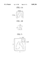
- FIG. 45 is a diagram showing a lung nodule detected by a CAD-processing.
- FIG. 46 is a diagram showing the region of interest (ROI) set by CAD in order to detect interstitial lung disease.
- ROI region of interest
- FIG. 47 is a diagram showing the interstitial lung disease detected by the CAD processing.
- FIG. 48 is a figure showing abnormality regions (Y1 and Y2) determined by the interstitial lung disease result obtained by CAD.
- FIG. 49 shows data representing a position (location) of abnormality.
- FIG. 50 is a table showing the abnormality data.
- FIG. 51 is a table showing overlay display information whereby the position (location) of abnormality is shown.
- FIG. 52 is a table showing the data attached to the image.
- FIG. 53 is a diagram showing remarks 8findings) on the image input by the reading (interpreting) doctor.
- FIG. 54 is an example of a format of the interpreting report which is displayed on a screen of the character display unit (WS-CDISP).
- FIG. 55 shows part of doctor's reading (interpreting) report.
- FIG. 56 shows a view showing abnormality regions inputted by the reading doctor, expressed in a coordinate system.
- FIG. 57 shows a view showing abnormality regions detected by the CAD, where an image therefor is expressed in the coordinate system.
- FIG. 58 and FIG. 59 show an example for voice input together with position input, according to the fourth embodiment.
- FIG. 60 and FIG. 61 show an example for reading of the characters or the like, according to the fourth embodiment.
- FIGS. 62A-107 show the fifth and sixth embodiments.
- FIGS. 62A and 62B are flowcharts and configurations for explaining the gist of the fifth embodiment in the broadest sense.
- FIGS. 63A and 63B are flowcharts and configurations for explaining the gist of the sixth embodiment in the broadest sense.
- FIG. 64 is tree-type chart showing relationship between the patient ID number, examination ID number and the examination data ID number.
- FIGS. 65A and 65B illustrates a case where the examination data ID number is searched from the examined patient ID number.
- FIGS. 66A and 66B illustrates a case where the examined patient ID number is searched from the examination data ID.
- FIGS. 67 through 69 show abnormality data tables with various judgment values set according to the first variation of the fifth embodiment.
- FIGS. 70 through 79 show abnormality data tables in the images of the examination ID numbers 920002 to 920010.
- FIG. 80 shows the classified results of the images of the examination ID numbers 920001 to 020010.
- FIGS. 81, 82, 83 show the created lists A, B, C, respectively.
- FIG. 84 shows a abnormality data table.
- FIG. 85 shows the classified result of the images of the examination ID numbers 930001 to 930010.
- FIGS. 86, 87, 88 are created lists A, B, C, respectively.
- FIG. 89 is a table showing a process for calculating abnormality values in the lung nodule of an image whose examination ID number is 940001.
- FIG. 90 is a table showing a process for calculating abnormality values in the interstitial lung disease of an image whose examination ID number is 940001.
- FIG. 91 is a table showing abnormality data of the image whose examination ID number is 940001.
- FIG. 92 is a table showing the classified result of the images of the examination ID numbers 940001 through 940010.
- FIGS. 93, 94, 95 are created lists A, B, C, respectively, where the classified results falling under case A, case B and case C are respectively registered in list A, list B and list C.
- FIG. 96 is an abnormality data table for the image whose examination ID number is 920001.
- FIG. 97 is a table showing the classified results of the images of examination ID numbers 920001 through 920030, according to embodiment no. 6-1.
- FIGS. 98, 99, 100 are the created lists A, B, C, respectively, where the second classified results falling under case A, case B and case C are respectively registered in list A, list B and list C.
- FIG. 101 is the abnormality detailed data table concerning the image of the examination ID number 920002.
- FIG. 102 is a finding data table for the image of the examination ID number 920002.
- FIG. 103 shows overlay display data for the doctor's reading.
- FIG. 104 shows overlay display data for the CAD-processed result, concerning the examination ID number 920002.
- FIG. 105 is a list showing the abnormality detection result.
- FIG. 106 is a table showing the results where the doctor's interpretation results and the CAD-processed results are compared and classified.
- FIG. 107 illustrates the classification obtained from the comparison result, expressed in a set (in a type of Venn diagram).
- FIG. 108 shows a schematic configuration of a medical archiving communication system (PACS) to describe the seventh embodiment.
- PACS medical archiving communication system
- FIG. 109 shows system manager 1 shown in FIG. 108.
- FIG. 110 illustrates construction of database 3 shown in FIG. 108.
- FIG. 111 illustrates construction of workstation 4 shown in FIG. 108.
- FIG. 112 shows typical disease images.
- FIG. 113 is an embodied configuration of the image aquisition units 2A, 2B shown in FIG. 108.
- FIG. 114 is a flowchart showing the procedures of judgments of necessity of the additional examination.
- FIG. 115 is a detailed flowchart of block A shown in FIG. 114.
- FIG. 116 is a detailed flowchart of block B shown in FIG. 114.
- FIG. 117 is a display image plane indicating a case where the next examination is not necessary.
- FIG. 119 is a display image plane indicating a case where the next examination is to be conducted.
- FIG. 120 is a table showing an example of the examination request information, according to embodiment no. 7-1.
- FIG. 121 is a table showing an example of the annexed information.
- FIG. 122 is a table showing an example of the interpretation report.
- FIGS. 123-128 show various reference order rules.
- FIG. 129 is a table showing an example of the abnormality data.
- FIG. 130 is a table showing an example of he examination histories.
- FIG. 131 is a table showing an embodiment of the annexed information.
- FIG. 132 is a table showing an embodiment of the examination request information.
- FIG. 133 is a table showing an embodiment of the annexed information.
- FIG. 134 is a table showing an embodiment of the renewed examination histories.
- FIG. 135 is a table showing an embodiment of the renewed abnormality data.
- FIG. 136 is a table where the first and second priority orders of the reference priority order information are written in this order.
- FIGS. 137A and 137B are tables showing an embodiment of the annexed information of the typical disease example image having the identical type of abnormality (interstitial lung disease) to the uninterpreted image.
- FIG. 138 is a table showing an embodiment of created reference priority order information.
- FIG. 139 is a table showing an example in the case where a type of abnormality is interstitial lung disease.
- FIG. 140 is a table showing an example in the case where the type of abnormality is lung nodule.
- FIG. 141 illustrates embodiment no. 7-4.
- FIG. 142 is a table showing an example of the typical sentences, according to the eighth embodiment.
- FIG. 143 is a table showing an example of the overlay display information.
- FIG. 144 is a table showing an embodiment of the overlay display information.
- FIG. 145 is a table showing an interpretation report made based on the overlay display information of FIG. 144.
- FIG. 146 is a table showing a new interpretation report.
- FIG. 147 is a table showing another new interpretation report to which paragraph "expanding to a wide scope" is added.
- FIG. 148 illustrates construction of workstation according to the eighth embodiment.
- FIG. 149 illustrates a moving pitch of a cursor displayed on the image plane.
- FIG. 150 shows a figure made in the overlay data forming portion.
- FIG. 151 illustrates an example of the display screen where a type of arrow in a solid line is used.
- FIG. 152 another example of the display screen where other type such as an arrow in a dotted line can be selectively added thereto.
- FIG. 153 shows an example where the minified image is displayed in an image display unit different from another image display unit displaying the original image thereon, according to the first embodiment.
- FIG. 1 is a block diagram showing the entire configuration of a Picture Archiving Communication System (hereinafter referred to as "PACS") containing a medical information processing system according to this embodiment.
- PACS Picture Archiving Communication System
- a network 5 serves as transmission paths for commands and data communicated among components.
- Optical fibers are used as transmission media.
- the network 5 is herein formed as a ring local area network. Of course, a star or other networks will also do.
- the network 5 is connected with a system manager (SM) 1, image acquisition apparatuses (IA) 2a, 2b, a database (DB) 3 for storing medical images acquired by the image acqusition apparatuses 2a, 2b, and workstations (WS) 4A, 4B, and this system can respectively be communicated each other with a communication protocol.
- SM system manager
- IA image acquisition apparatuses
- DB database
- WS workstations
- This network 5 is connected with an examination order system 7 through a gateway 6.
- This examination order system 7 is located in a room of an examination request; department and indicates the request of image examination by preparing examination request information.
- This examination request information contains respective items such as a patient ID number, a patient name, a date of birth, a sex, an examination requesting department, a name of examination requesting doctor, an examination modality (an X-ray machine, an X-ray computered tomography machine, a magnetic resonance imaging machine, or the like), a region to be examined, a procedure of examination, a purpose of examination, a clinical information, and the like.
- the information of each item is manually inputted into the examination order system 7 by the examination requesting doctor.
- This examination request information is transferred 35 to the system manager 1 after required items have been finished inputting and appropriate image acquisition apparatuses 2a, 2b are selected therein in accordance with this requesting contents to transfer the information again from the system manager 1 to such selected image acquisition apparatuses 2a, 2b.
- the image acquisition apparatuses 2a, 2b are apparatuses for aquiring a medical image (hereinafter referred simplly to as "image") such as an X-ray machine, an X-ray computed tomography machine, a magnetic resonance imaging machine, a film digitizer, or the like. Additional information as shown in Table 2 is attached to this image, which is transferred to the database 3 to be stored therein.
- the additional information or data is prepared per examination unit, including an examination ID, a date of examination, and the information of each image acquired by such examination. Furthermore, the information of image includes an image number, an image size, a data amount, and an imaging direction.
- the system manager 1 After the image acqusition has been completed, the system manager 1 creates an examination history from the examination request information (data) and the additional information (data). Furthermore, an interpreting doctor prepares an interpretation report of the image and manually inputs it by using the image acqusition apparatuses 2a, 2b. (Terms interpreting doctor, reading doctor and radiologist are interchangeably used throughout this application.) One example of the examination histories will be hereinafter described.
- the medical computer-aided diagnosis system is incorporated into the workstations 4A, 4B in this PACS.
- the workstations 4A, 4B will be hereinafter explained.
- the workstations 4A, 4B are provided with the following functions:
- the workstations 4A, 4B are constituted as shown in FIG. 2.
- control buses WS-CBUS
- WS-IBUS image bus
- a control 4a contains a central processing unit (CPU) or a system memory (for example, a semiconductor memory device), and controls the operations of the entire workstation and also executes various oparating processes.
- CPU central processing unit
- system memory for example, a semiconductor memory device
- a system disk 4b is, for example, a magnetic disk, and stores programs or data described below and also reads out these programs or data when an electric power is switched on to supply them to a system memory within the control 4a.
- the program (OS) and abnormality detection means selecting data for operating in relation to each part constituting the workstation.
- the abnormality detecting means denotes an algorithm capable of detecting a specified abnormality, and is stored in a CAD processor 4e.
- a typical device of the abnormality detecting means there are three species of abnormality detecting means capable of detecting a pulmonary interstitial disease, abnormality detecting means capable of detecting pulmonary nodules, and abnormality detecting means capable of detecting a fine calcification of a breast.
- the abnormality detection means selecting data is a table of a type of image (an examined region, a modality, a procedure of examination, an imaging direction) corresponding to a type of abnormalities.
- the type of abnormalities capable of detecting corresponding to the type of images is determined. The above correspondence is based on it.
- abnormality detection means select information is shown below.
- This abnormality detection means selecting information is used when selecting the abnormality detecting means capable of analizing such image at diagnosing images by the CAD processor 4e.
- this abnormality detection means selecting data can be rewritten (renewed) and added thereto.
- An input unit 4c is means for inputting various commands such as an image retrieval or the like by a doctor and also manually inputting finding data after he/she observes the image, and for example, a keyboard or a mouse is used.
- the finding data consists of a type of abnormality, its position (XY-coordinates of an image matrix), a degree of abnormality, or the like.
- these finding data are summarized in a finding data table for each type of abnormality. This finding data table is identical to the abnormality data table which is outputted as a result of diagnosis in the below-mentioned CAD processor 4e in items of its contents.
- a cursor is doubly displayed on the original image corresponding to movements of a mouse.
- the cursor is put upon the image showing abnormalities by moving the mouse.
- a left button of the mouse is clicked, the position is recognized.
- the system acknowledges that such input position has not be inputted by clicking an inside button of the mouse. It is fairly favorable in operating the system that a move pitch of the cursor is set as about 32 pixels when an image matrix is 2,048 ⁇ 2,048 pixels.
- the system synchronizes with the click of the left button of the mouse to display a message, for example, "input the type of abnormality" on the screen.
- a character display 4d is a device for displaying mainly characters such as interpretation (reading) reports etc., and for example, a CRT (Cathode Ray Tube) display, a liquid crystal panel display, or the like is used.
- CRT Cathode Ray Tube
- a CAD processor 4e is provided with a function of a Computer-Aided Diagnosis, receives an instruction of activation from the control 4a, performs the CAD processing (diagnosis processing) on inputted images by this function, and creates the abnormality data table finally.
- CAD processing diagnosis processing
- the abnormality data table consists of respective items of a reference number, an examination ID number, a type of abnormality, a central position of abnormality on an image, and a degree of abnormality.
- the CAD processor 4e contains the plural species of abnormality detecting means as described above. That is, as a typical embodiment, there are provided: (a) means for detecting a shadow of a pulmonary interstitial disease in a front side image of a chest plain X-ray image; (b) means for detecting a shadow of a pulmonary nodules in a front side image of a chest plain X-ray image; and (c) means for detecting a shadow of a fine calcification of a breast in a breast X-ray image.
- a digital image (hereinafter referred to as an "original image") is transferred from the database 3 to the CAD processor 4e. Furthermore, under an instruction of the control 4a, information of the type of abnormality corresponding to such original image of the abnormality detection means selecting data of the system disk 4b is transferred. Any abnormality detecting means is selected corresponding to the type of this abnormality. The original image is analyzed by the selected abnormality detecting means. If there is an abnormality, the central position on an image of this abnormality (XY-coordinates of an image matrix) and the degree of the abnormality are acquired. The above-mentioned abnormality data table containing these position and degree of abnormality is created by the CAD processor 4e. The abnormality data table is transferred to the below-mentioned image storage 4f and stored therein.
- An image storage 4f is, for example, a magnetic disk, and a device for temporarily storing examination request information derived from the examination order system 7, examination histories, an interpretation (reading) report, additional information to image, original image data, overlay display information (image data showing abnormalities), an abnormality data table, and a finding data table.
- An image frame memory 4g is, for example, a semiconductor memory and a device for temporarily storing at least a sheet of original image to be interpreted which is transferred from the database 3.
- An image display 4i is, for example, a color CRT display and a plurality of image displays, herein four image displays, are prepared.
- This image display 4i is a device for displaying mainly an image.
- respective image display units may present different resolutions and so on.
- An image data reduction unit 4p receives the original image of the image frame memory 4g through the image bus 4l, and for example, this is minified to a reduced image of 1/8. That is, as shown in FIGS. 4A, 4B, if an image matrix size of the original image is a ⁇ b pixels, the reduced image is an image matrix size of a/8 ⁇ b/8. For example, if the image matrix size of the original image is 2,048 ⁇ 2,048 pixels, the reduced image consists of 256 ⁇ 256 image matrixes.
- This reduction processing is, for example, a leveling reduction filter processing.
- the leveling reduction filter processing is that the original image is partitioned into a plurality of minute areas of 8 ⁇ 8 pixels and a simplified average or a weighted average of a pixel value in each area is defined as a pixel value of one pixel of the reduced image.
- the other reduction processing may be adopted.
- the reduced image created by the image data reduction unit 4p is sent to a display image data overlay unit 4q as described later.
- a minifying factor may be 1/1.
- a display image data overlay unit 4q synthesizes the original image to be interpreted which is stored in the image storage 4f with the reduced image of this original image which is created by the image data reduction unit 4p to generate a sheet of composite image to be displayed.
- a composite processing will be explained with reference to FIG. 5.
- the pixel matrix size of the reduced image is a/8 ⁇ b/8 pixels as described above.
- a part of the original image is completely substituted for pixels of the reduced image.
- a substituted area is specified by four points (a-a/8, 0), (a, 0), (a, b/8), (a-a/8, b/8) in the original image.
- the original image is synthesized with the reduced image to create a synthetic image. This synthetic image is transferred to the image storage 4f and stored therein.
- a schema data (or schematic diagram data) making storage 4r inputs an image, digitizes it to abstract an outline of lungs or ribs, makes a schema (or schematic) image (contour image) as shown in FIG. 6, and stores it.
- a threshold value of digitization is 512
- a pixel value f (x,y) of a certain pixel (x,y) is the threshold value or greater
- such pixel value is substituted for 1023.
- the pixel value f (x,y) of the certain pixel (x,y) is less than the threshold value, such pixel value is substituted for 0.
- An overlay display information maker 4n inputs either the abnormality data table or the finding data table concerning such original image stored in the image storage 4f, the overlay display information maker 4n makes overlay display information as shown in the following Table 7:
- this overlay display information information of each of items of a type of a graphic, a size of a graphic, and a display color is added to the items of the abnormality data table and the finding data table. These additional information is required to superimpose information of abnormalities on the synthetic images, and as shown in FIG. 7, the contents have beforehand been set.
- the type of a graphic indicates a graphic for showing the position of abnormality on the image, and for example, this is information indicating to display as a shape of an arrow.
- the size of a graphic is information indicating that such arrow should be shown in a size to be received within a scope of, for example, 32 ⁇ 32 pixels.
- the display color is one of such arrow, and information indicating that such arrow should be shown in white.
- the coordinates of overlay display information are that the coordinates indicating a central position of the abnormality which is written into the abnormality data table are converted into coordinates on the reduced image of the sysnthetic image.
- the overlay display information is transferred to the image storage 4d to be once stored therein.
- An image display manager 4h is a control concerning a display such as an original image etc. and constructed as shown in FIG. 3.
- An image memory 42 receives the synthetic image stored in the image storage 4f through the image bus 4l to be stored therein.
- the image memory 42 has storage capacity of, for example, 2,048 ⁇ 2,048 ⁇ 10 bits so as to store at least a sheet of synthetic image.
- Information of a display mode set by the input unit 4c (a mode displaying only an original image, a mode displaying only abnormality information, a mode displaying synthetic images of the original image and the abnormality image on one screen) and information specifying the image display 4i for use in the display are supplied to a control unit 40 through the control bus 4k.
- overlay display information is supplied from the image storage 4d to the control unit 40.
- An overlay data creator 41 receives the overlay display information from the control unit 40 and creates overlay data to display the abnormality information (the information showing a type, a position, and a degree) on the reduced image based on this overlay display information. These overlay data are temporarily stored in one overlay memory 43a.
- the other overlay memory 43b is a memory for storing data of a cursor displayed on a display screen in response to movements of a mouse.
- An overlay unit 44 creates an overlay display image by superimposing the overlay data on the synthetic image.
- This overlay display image is displayed on the set image display 4i through display memories 45 and D/A converters 46 corresponding to the image display 4i corresponding to information specifying the image display 4i for use in a display set by the input unit 4c.
- the examination request information inputted through the examination order system 7 is transferred to the system manager 1.
- One example of this examination request information is shown in table 8 as described below.
- This additional information is transferred to the database 3 together with the image to be stored therein and will stand by until it is read out to interpret it.
- a readout demand of the image to be interpreted is sent from the workstation 4A to the database 3.
- Such image (including the additional information) is sent back to the workstation 4A together with the examination histories of such patient, the past interpretation report, and the examination request information to be stored in the image storage 4f.
- the abnormality data table is created by the CAD processor 4e.
- image is displayed on the image display 4i and observed by an operator to input the results through the input unit 4c. Consequently, the finding data table is created.
- One example of the abnormality data table is shown in Table 10. Furthermore, one example of the finding data table is shown in Table 11.
- the original image is read out of the database 3 and stored in the image storage 4f. It is transferred to the image data reduction unit 4p and the display image overlay unit 4q.
- the original image is minified at a predetermined reduction rate, herein at 1/8, by the image data reduction unit 4p.
- This reduced image is sent to the display image overlay unit 4q and synthesized into the original image and a sheet of synthetic image therein. As this synthesis processing is above-mentioned, the description is omitted.
- this synthetic image can be made instead of the above-mentioned reduced image.
- the schema image made by the schema data making storage 4r can be reduced by the image data reduction unit 4p to create a reduced image which is synthesized with the original image to create the synthetic image.
- the abnormality data table (or the finding data table) is supplied from the image storage 4f to the overlay display information maker 4n to make the overlay display information based on this abnormality data table.
- the type thereof is an arrowheaded real line and a size thereof is 32 ⁇ 32 pixels and a display color is white.
- the position of abnormality in the abnormality data table is determined with coordinates defined by a coordinate system of the original image, it is necessary to transform these coordinates into coordinates on the reduced image of a display image. For example, if a pixel matrix size of the original image is 2048 ⁇ 2048 pixels and the position of abnormality in the abnormality data table in this coordinate system is (a,B), the coordinate of such position of abnormality is converted into coordinates (2048-2048/8+a/8, B/8).
- the information of abnormality is supperimposed on the reduced image by this coordinate transformation to be displayed.
- Table 12 One example of the overlay display information created based on the abnormality data table as shown in Table 10 is shown in Table 12 described below.
- the abnormality data table of Table 10 has data such as the position of abnormality on the image (350,1350), the degree of an abnormality "9", and the type of abnormality "pulmonary interstitial disease”. According to this information, the position of abnormality (1835,168) which is obtained as a result of the coordination transformation, the degree of abnormality "9", the type of abnormality "interstitial lung disease", the type of graphic "arrowheaded real (solid) line", and the display color "white” are written into the data number 1 in the overlay display information.
- the position of abnormality (1841, 187), the degree of abnormality "8", the type of abnormality "interstitial lung disease”, the type of graphic "arrowheaded real (solid) line”, and the display color "white” are written into the data number 2.
- the result of coordinate conversion contains a decimal point or less, it is rounded to the nearest whole number to be treated as an integer value.
- the thus-created overlay display information is stored in the image storage 4f.
- the synthetic image created by the display image overlay unit 4q is transferred from the image storage 4f to the image memory 42 of the image display manager 4h to be stored therein.
- the overlay display information created by the overlay display information maker 4n is sent from the image storage 4f to the overlay data creator 41 through the control unit 40 in the image display manager 4h.
- a display mode inputted from the input unit 4c herein, this is a display mode by superimposing the overlay image on the original image
- information specifying the image display 4i to be displayed are supplied to the control unit 40.
- the following overlay data are created based on the overlay display information in the overlay data creator 41 and stored in the overlay memory 43a.
- bits are erected in an arrowheaded shape in coordinates (1835,168) of the overlay memory 43a, and in the character display of the degree of abnormality "9" and the type of abnormality "interstitial lung disease", bits are erected in a character shape on the overlay memory 43a using a character font in the control 4a.
- bits are erected in an arrowheaded shape in coordinates (1841,187) of the overlay memory, and in the character display of the degree of abnormality "8" and the type of abnormality "interstitial lung disease”, bits are erected in a character shape on the overlay memory 43a using a character font in the control 4a.
- This overlay data are supplied to the overlay unit 44 together with the synthetic image of the image memory 42 and superimposed thereon to be displayed in the image display 4i specified by the input unit 4c.
- This display example is shown in FIG. 9.
- FIG. 10 when images in which the schema image is synthesized with the original image are displayed instead of the reduced image, its display example is shown in FIG. 10.
- An interpreting doctor interprets the images which are superimposed on the overlay data, and inputs its interpretation results from the input unit 4c to create the interpretation report.
- This interpretation report is transferred to the image storage 4f to be stored therein. Furthermore, the interpretation report is transferred from the image storage 4f to the database 3 through the system manager 1 to be stored therein.
- the reduced image (or -the reduced image of the schema image) is disposed in a part of the original image and the information of abnormalties is displayed on this reduced image, even if an object of the original image is interfered with the information of abnormalities, the image never disappears and a doctor can interpret the original image on one screen referring to the information of abnormalities. Accordingly, it becomes unnecessary to change between the display of only the original image and the display of the image which superimposes the information of abnormalities on the original image, thereby enhancing operator productivity.
- the present invention is not limited to the above-mentioned embodiments, which can be variously changed to execute the other embodiments.
- the original image is smoothened by the reduction filter processing.
- the other technique can be utilized.
- the reduced image can be created by sampling scattered pixels of the original image.
- a sheet of reduced (minified) image is superimposed on the original image, however a plurality of sheets of reduced image can be superimposed thereon each type of abnormality.
- a shape or display color of a graphic of the overlay data is one type only, however the shape or display color of a graphic can be changed for each type of abnormality.
- a position of abnormality is shown with an arrow, however the other graphics such as a round, a square, or the like can be used.
- the CAD processor is provided with three types of abnormality detecting means, however the other types of abnormality detecting means can be used and also the type of image to which the abnormality detecting means is applied is not limited.
- each pixel value of the schema (schematic) image is digitized at a threshold value to make the schema (schematic) image, however it may also be made by contour extracting means such as a contour line tracing tomography machine etc.
- the schema image is made from the original image at displaying the image, however the schema image has beforehand been made before displaying the image to be stored in a system disk so that it may be used at displaying the image.
- the reduced (minified) image may be displayed in other display unit than that displaying the original image.
- the original image is displayed in image display unit (WS-IDISP-1) 4i
- the reduced image, in which the arrow is superimposed is displayed in another image display unit (WS-IDISP-1) 4i.
- a medical information processing system comprises: means for inputting an image; means for inputting a position of an abnormal spot containing said image; means for making a reduced image by reducing (minifying) said image; means for creating a synthetic image by synthesizing said image with said reduced image; means for creating a display image by superimposing a graphic showing said abnormal spot on said reduced image of said synthetic image based on said position; and means for displaying said display image.
- the graphic showing the abnormal spot is superimposed on the reduced image of the synthetic image which synthesizes the image with the reduced image to display it, whereby even if an object of the image is interfered with the abnormal graphic, the object never disappears, and the original image can be interpreted referring to information of abnormalities on one screen. Accordingly, it is possible to provide the medical information processing system in which it becomes unnecessary to change between the display of only the original image and the display of the image which superimposes the information of abnormalities on the original image unlike the prior art, thereby enhancing operator productivity.
- FIGS. 13A, 13B and 14 are flowcharts for explaining the gist of the present invention.
- FIGS. 13A and 13B shows the gist of a second embodiment and
- FIG. 14 shows the gist of a third embodiment.
- FIG. 13A shows the gist having the broadest sense in the second embodiment.
- This is the embodiment in which a plurality of diagnostic results having one or more diagnostic data obtained by a medical group examination or mass survey or the like within a medical information processing system exist, and these diagnostic results are to be compared or classified. Assuming that a plurality of diagnostic results are diagnostic results A and diagnostic results B, these results are first compared and classified in each diagnostic information. Next, a great amount of diagnostic information is classified in a listing form etc. and selected and outputted to report.
- the diagnostic results A and the diagnostic results B may be diagnostic results obtained by the plurality of doctors and may be CAD processing (diagnostic) results and doctors' interpretation (diagnostic reading) results.
- the latter case will be explained in FIG. 13B and herein the former case will be explained. That is, doctors A and B interpret images in a workstation WS to obtain interpretation results, which are inputted into a database DB, and then a great amount of diagnostic information inputted is compared and classified to be divided into two categories in which a close examination is necessary or unnecessary.
- identification information of its medical examination data or the medical examination data and diagnostic information and information relating to the medical examination data are outputted.
- the diagnostic information is classified that a close examination is unnecessary, the identification information of the medical examination data and the doctor's diagnostic information are outputted.
- FIG. 13B is a case of comparing the CAD processing results with the doctor's diagnostic results.
- Information concerning a hearing examination or disease histories is inputted from a hearing information input unit HI and image data of a certain type of medical examination data are inputted from an image acquisition unit IA.
- each image data is CAD-processed to detect an abnormality to obtain the result to create an abnormality data table.
- the image data, the hearing information, or the like are sent from the database DB to the workstation WS to display the image data therein and a doctor interprets the images.
- An interpreting doctor creates a finding data table which is interpretation results for each image data to be input therein.
- the doctor When the doctor finishes interpreting the images, he/she compares this finding data table with the abnormality data table which is the CAD processing results and can classify it to create an abnormality detecting result list which is its results, in order to output it for each classification.
- the doctor re-interprets the images, he/she outputs (including a display) his/her own favorable classification to complete finding data, and sends the results from the workstation WS to the database DB to be registered therein.
- the interpretation in the medical group examination is carried out by two or more doctors, and this completed finding data is sent to the database DB in at least two sets. After a plurality of interpretations are inputted into the database DB, this system operates as described in FIG. 13A described above.
- FIG. 14 shows the gist of the third invention.
- Information concerning an oral examination or disese histories is inputted from the hearing information input unit HI, and image data which are a certain type of medical examination data are inputted from the image acqusition unit IA.
- each image data is CAD-processed to detect an abnormality before a doctor interprets the image data, in order to create the abnormality data table which is its results.
- a doctor interprets the images.
- the CAD processing results created previously can be referred to.
- FIG. 15 shows an embodiment having a basic system configuration of the PACS.
- This system is constructed of the following units (subsystem):
- the hearing information input unit (HI) is a device for inputting hearing information or disease histories which are obtained by an oral examination to examined persons.
- the image acquisition unit (IA) is a medical image acqusition unit for the PACS such as an X-ray machine, an X-ray CT machine, an MRI machine, a film digitizer or the like. Herein, it is defined as an X-ray machine which is placed on a medical examination car.
- the database (DB) is used for storing various data to be produced in operations of the medical examination.
- the workstation (WS) appropriately processes digital images etc. sent from the database (DB) or the image acquisition unit (IA) to obtain desired results to display or output them.
- the workstation is used for interpreting radiographed images.
- Communications among these four types of units are carried out by using a data memory medium capable of carrying and rewriting, such as an optical magnetic disk or the like.
- the hearing information input unit (HI) can readily be realized by adapting a personal computer to be obtained in the market. As the configuration has no connection with the gist of the present invention, the description is omitted.
- the configuration of the image acquisition unit (IA) is shown in FIG. 17.
- a control unit contains a central processing unit (CPU) or system memories (namely, semiconductor memory) etc. and controls operations of the entire image acqusition unit.
- CPU central processing unit
- system memories namely, semiconductor memory
- IA-SD IA-SD
- IA-INPUT Input Unit
- IA-DISP Display Unit
- the X-ray imaging unit for example, a semiconductor memory or a magnetic disk
- This is a device for reading data out of portable optical magnetic disk or writing data thereinto.
- a clock (not shown in FIG. 18) is integral with the image acquisition unit.
- the database stores identification information of an examined person, hearing information, image data, and information attached to examination information and an image.
- the database stores findings which are doctors' interpretation results.
- the database detects images having doubtful abnormalities from image data.
- the database can write various data into the portable optical magnetic disk or read them out of it.
- a configuration element and a function in the database (DB) will be described.
- the configuration of the database (DB) is shown in FIG. 19.
- CPU central processing unit
- system memories namely, semiconductor memory
- the search unit includes a directory of information stored in the database and searching means. A magnetic disk is used as storing means of the directory.
- (b) means for detecting shadows of interstitial lung disease in a front side image in a chest X-ray image.
- abnormalities such as a type of abnormalities (disease), a position and degree of abnormalities, or the like.
- FIG. 20 is a configurational diagram of the workstation (WS).
- CPU central processing unit
- system memories namely, semiconductor memory
- the touch screen is mounted onto a screen of the display unit (WS-DISP).
- FIG. 21 is a configurational diagram of the image display manager (WS-IDM) and a part of the image display manager (WS-IDM) is shown within a broken line.
- overlay data (color) from overlay display information.
- the overlay memories corresponding to one screen are constructed of three sheets of overlay memory for red, green, and blue.
- a matrix size is conceptionally 2,048 ⁇ 2,048 pixels, and a bit length of 1 pixel is 1 bit.
- FIG. 22 The relationship between a display color and a bit value of each pixel is shown in FIG. 22.
- a pixel value (a bit value of pixel) of a pixel coordinate (X, Y) of the overlay memory for red is 1, and a pixel value of the same coordinate of the overlay memory for both green and blue is 0, and a red color is displayed as to the coordinate.
- black in a display color means that any colors are not displayed, and when black is doubly displayed on an image, only the image is displayed;
- An overlay portion superimposes image data on overlay data
- This image display manager has two sheets of memory for displaying a sheet of image (a matrix size is 2,048 ⁇ 2,048 pixels). This is equal to the number of the display units (WS-DISP).
- the memories for displaying correspond to the display units (WS-DISP), respectively;
- the image display manager can receive the following information:
- One of three types can be displayed: an image only, an overlay only, an image and an overlay;
- the image display manager When displaying an image overlapping an overlay, the image display manager (WS-IDM) operates in the following manner:
- the control portion of the image display manager receives the below-mentioned three information from the control unit (WS-CTRL) of the workstation (WS):
- the image display manager receives image data and writes them into the image memories.
- the overlay data making portion makes overlay data based on overlay display information by an instruction of the control portion. Then, when control information of present or absence of display is "display", the overlay data making portion makes the overlay data with an indicated graphic, indicated coordinates, and indicated color data.
- the image data and overlay data are read out by an instruction of the control portion to input them into the overlay portion to synthesize the data.
- the synthesized data are written into dispalying memories with an indicated display unit number.
- the overlay data making portion writes the graphic into the overlay memories to display it.
- the overlay data making portion receives:
- a color display is available. In this embodiment, two units are set.
- a clock for referring to a date and a time (not shown in the figure) is integral with the workstation (WS).
- a hearing sheet is displayed on a display screen of the hearing information input unit (HI).
- An Operaator inputs examined person identification information from the hearing information input unit (HI).
- the examined person identification information is assigned to the examined person so as not to overlap each other within such medical examination area, and an examined person ID number described in a register shall here be inputted.
- the inputted data are displayed in a specific position on a screen.
- the control unit of the hearing information input unit reads out hearing information (examined person identification information and responses from the examined persons) stored in the system disk by an instruction of an operator, and writes it into the optical magnetic disk inserted into the optical magnetic disk drive (HI-MODD).
- An operator inputs examined person identification information from the input unit (IA-INPUT) of the image acquisition unit (IA).
- the inputted data are displayed in a specific position on a screen of the display unit (IA-DISP).
- the control unit (IA-CTRL) indicates to expose X-rays and image to the X-ray generator (IA-XGEN) and the X-ray imaging unit (IA-IMG).
- the X-ray generator (IA-XGEN) generates X-rays and irradiates them onto a person to be exposed (person to be examined).
- the X-rays transmitted through the person to be exposed are detected by the X-ray imaging unit (IA-IMG) to obtain digital images.
- the X-ray imaging unit (IA-IMG) transmits image data to the image bus (IA-IBUS).
- the image data unit (IA-IM) receives the image data to write them to itself.
- the control unit (IA-CTRL) writes information attached to imaging conditions or images together with examined person identification information into the system disk (IA-SD).
- the control unit reads out information attached to an examination and an image which is stored in the system disk (IA-SD) by an instruction of an operator, and writes it into an optical magnetic disk inserted into the optical magnetic disk drive (IA-MODD).
- control unit (ii) The control unit (IA-CTRL) successively reads out image data from the image data unit (IA-IM) and writes them into the optical magnetic disk inseted into the optical magnetic disk drive (IA-MODD).
- An operator inserts the optical magnetic disk registering hearing information into the optical magnetic disk drive (DB-MODD) of the database (DB), and inputs a hearing information readout command of the optical magnetic disk from the input unit (DB-INPUT). Then, by an instruction of the control unit (DB-CTRL), the optical magnetic disk drive (DB-MODD) reads out the hearing information registered in the optical magnetic disk and writes it into the data storing unit (DB-STRG).
- the control unit (DB-CTRL) extracts information (hereinafter, referred to as directory information. Refer to FIG. 2;3) registered in a data directory from the hearing information to send it to the search unit (DB-SRCH).
- the search unit (DB-SRCH) stores the received directory information.
- control unit extracts the previously radiographed image data of examined persons (hereinafter, called previous image data or image data in the past) from the examined person identification information of the hearing information from the data storing unit (DB-STRG) to send them to the search unit (DB-SRCH).
- search unit adds the received previous image data to the directory information.
- the control unit (DB-CTRL) of the database (DB) indicates to search the images (comprisised of images to be interpreted and previous images) registered in the search unit (DB-SRCH) to obtain a response. Successively, the control unit (DB-CTRL) indicates to perform the following abnormality detecting operations for each sheet of images.
- the detected abnormality is represented by shadows of pulmonary nodules.
- Image data corresponding to a sheet of image are read out from the data storing unit (DB-STRG) to send them to the image processing unit (DB-IP).
- the image processing unit (DB-IP) receives the image data and operates pulmonary nodules shadow detecting means having inside to detect specific positions on the images having doubtful abnormalities.
- the detected positions of abnormalities are recognized by an absolute coordinate system on coordinate axes formed by an image upper end and an image left end as shown in FIG. 24, and written into the abnormality data table as shown in FIG. 25.
- abnormal shadows are detected at two positions of N1 (700, 1200) and N2 (1500, 1000).
- abnormality judgments on the entire image when the abnormality has not entirely been detected, "normal”, and when at least one abnormality has been detected, “doubtfully abnormal".
- the abnormality judgement on the entire image is made as a "doubtful abnormality”.
- the abnormality data table showing detection results are stored in the data storing unit (DB-STRG).
- the abnormality data tables in the images of the examination ID numbers 920002 to 920005 are shown in FIGS. 26 to 29.
- the control unit (DB-CTRL) of the database (DB) indicates the data storing unit (DB-STRG) to read out data of images to be interpreted, previous image data, hearing information, and information attached to an examination and an image (containing an abnormality data table), and indicates the optical magnetic disk drive (DB-MODD) to write them.
- the data storing unit (DB-STRG) reads out these data to be sent to the image bus (DB-IBUS).
- the optical magnetic disk drive (DB-MODD) receives these data to write into the optical magnetic disk.
- An operator inserts the optical magnetic disk registering data of images to be interpreted, previous image data, hearing information, and information attached to an examination and an image into the optical magnetic disk drive (DB-MODD) of the workstation (WS) and inputs a data readout command derived from the optical magnetic disk from the input unit (WS-INPUT). Then, by an instruction of the control unit (WS-CTRL), the optical magnetic disk drive (DB-MODD) reads out the data stored in the optical magnetic disk and writes them into the data memory (WS-MEM).
- the data of images to be interpreted, the previous image data, the hearing information, and the information attached to an examination and an image are memorized corrresponding to each examined person.
- the workstation displays the images to be interpreted.
- a sheet of image to be interpreted (the examination ID number 920001) is automatically displayed on the left-sided display unit (WS-DISP) and the previous image (the examination ID number 910041) is automatically displayed on the right-sided display unit (WS-DISP).
- the examination ID number 920001 is automatically displayed on the left-sided display unit (WS-DISP)
- the previous image is automatically displayed on the right-sided display unit (WS-DISP).
- an image is displayed on the display unit (WS-DISP)
- its examination ID number (existent in information attached to an image) is displayed.
- the control unit reads out the coordinates of the abnormality position inputted to store it, and creates a finding data table as shown in FIG. 30. Then, the image display manager (WS-IDM) creates overlay display information describing "arrow, coordinare of abnormality position, white, and display" as to the abnormality in each finding number referring to the finding data table. The created overlay display information is shown in FIG. 31.
- the image display manager (WS-IDM) reates an overlay according to the overlay display information to display it. As a result, an arrow is displayed in a position that a doctor indicates on the image.
- the control unit (WS-CTRL) writes the overlay display information created into the data memory (WS-MEM) corresponding to the examination ID number.
- a doctor carrys out the same operations and adds information relating to an abnormality to an overlay to be memorized and displays on the image.
- the control unit When the finding data table is inputted as an abnormality, the control unit (WS-CTRL) writes the diagnosed results of the entire image as an "abnormality" into the finding data table, and when the finding data table is not inputted as an abnormality, the control unit (WS-CTRL) writes the diagnosed results of the entire image as a "normality" into the finding data table to memorize into the data memory (WS-MEM).
- the control unit reads out a finding data table which is interpreting results and an abnormality data table which is the corresponding CAD processing results from the data memory (WS-MEM).
- the image display manager creates the overlay display information from the abnormality data table indicating that a display color is "red” and memorizes it into the data memory (WS-MEM) corresponding to the examination ID number.
- the overlay display information created from the abnormality data table of the CAD processing results concerning the examination ID number 920001 is shown in FIG. 32.
- the control unit extracts both the diagnostic results of the entire image from the finding data table and the judged results of the entire image of the CAD processing from the abnormality data table to compare the both results to classify the following four cases:
- Case b The doctor judges as an "abnormality", but the CAD judges as a "doubtful abnormality”.
- Case c The doctor judges as a "normality", and the CAD also judges as a "normality”.
- Case d The doctor judges as a "normality”, but the CAD judges as a "doubtful abnormality”.
- the control unit reads out the abnormality detecting result list (if it does not exist, create it) and writes it into an examination ID number to be memorized into the data memory (WS-MEM).
- the explanation is made according to an example of the examination ID number 920001.
- the type of an abnormality is pulmonary nodules.
- a scope to be processed by the CAD is the entire image.
- a method of indicating the position of an abnormality by a doctor is the same as that by the CAD to show it with an arrow on the overlay. Accordingly, it is determined that the position of an abnormality shall be shown with a tip of an arrow to seek its coordinate. From FIGS. 25 and 30, the respective coordinates are A1 (1520, 1040), A2 (1430, 659), N1 (700, 1200), and N2 (1500, 1000).
- A1 and N2 indicate the identical abnormality and the information of controlling presence or absence of a display of N2 in the overlay display information of the CAD processing results is rewritten from a "display" to a "non-display". Only the CAD shall detect N1 and the doctor shall not indicate it, and the information of controlling presence or absence of a display is still a "display”. Also, only the doctor shall discover A2 and the CAD shall not detect it.
- the control unit writes the examination ID number of this image into the abnormality detecting result list.
- the control unit extracts the diagnostic results and the judging results for the entire image from the finding data table of the doctor and the abnormality data table of the CAD, and a part of results compared and classified is shown in FIG. 33.
- the interpreted images are 50 sheets of the examination ID numbers 920001 to 920050.
- the classified results were:
- control unit displays the classified results in Section 5, Subsection (4) in the display unit (WS-DISP) as shown in FIG. 34.
- the doctor selects the operations after classified as described in Section 5, Subsection (4).
- the doctor inputs an operation selection command from the input unit (WS-INPUT) to select an operation conforming to his/her way of thinking.
- the doctor shall select (a-2), (b-2), and (d-1).
- the control unit (WS-CTRL) operates (d-1) and creates an abnormality detecting result list.
- a doctor inputs a re-interpretation command.
- the control unit reads out the data of images to be interpreted which register the examination ID number in the abnormality detecting result list and the information relating to the examined persons (hearing information, information attached to an examination and an image (an abnormality data table, a finding data table, overlay display information), previous image data) from the data memory (WS--MEM), and superimposes the image to be interpreted on the overlay meaning his/her finding to display it on the left-sided display unit (WS-DISP) of two display units (WS-DISP), and superimposes the overlay meaning the CAD processing results concerning the image on the image to display it on the right-sided display unit (WS-DISP).
- the doctor reads an image and compares his/her finding with the CAD processing results.
- the doctor When displaying the images and the interpretation reports other than those displayed, the doctor inputs a command for it from the input unit (WS-INPUT) and operates.
- the control unit memorizes the corrected finding data table into the data memory (WS-MEM), and the overlay of the next image and the doctor's finding and the overlay of the CAD processing result, which are registered into the abnormality detecting result list, are displayed in the display unit (WS-DISP).
- the control unit reads out the finding data table concerning all the images to be interpreted from the data memory (WS-MEM) and writes it into the optical magnetic disk inserted into the optical magnetic disk drive (WS-MODD).
- An operator inserts the optical magnetic disk memorizing the finding data additionally into the optical magnetic disk drive (DB-MODD) of the database (DB), and inputs a finding data readout command of the optical magnetic disk from the input unit (DB-INPUT). Then, by an instruction of the control unit (CB-CTRL), the optical magnetic disk drive (DB-MODD) reads out the finding data memorized in the optical magnetic disk and writes them into the data storing unit (DB-STRG).
- the control unit (DB-STRL) extracts directory information from the finding data to be sent to the search unit (DB-SRCH).
- the search unit (DB-SRCH) stores the received directory information.
- Another sheet of optical magnetic disk is also registered into the database in the same manner.
- the two doctors' finding data concerning the identical examination image have been inputted into the database.
- An operator inputs an extracting command of persons to be made a close examination and an operation selecting command from the input unit (DB-INPUT) of the database (DB). Then, by an instruction of the control unit (DB-CTRL), the search unit (DB-SRCH) searches a finding data table of a chest X-ray examination which has not been made overall judgments of interpretation results (judgements as to whether a close examination is necessary or not), and reads out the examined person identification information and the two doctors' diagnostic result information in the system memory of the control unit (DB-CTRL).
- the control unit (ii) extracts the two doctors' diagnostic results of each examined person from the finding data table and the following comparison will be made:
- a deciding method of overall judgements can be selected. Selection may be made in the following manner:
- an operator inputs, from input unit (DB-INPUT), a command for selecting the above-mentioned operation ( ⁇ -1) and ( ⁇ -1) concurrently with a command of extracting persons to be made a close examination. Then, the overall judgements are transferred to the data storing unit (DB-STRG) and the search unit (DB-SRCH) corresponding to the examined person identification information to be stored therein.
- DB-STRG data storing unit
- DB-SRCH search unit
- the control unit reads out the overall judgements from the data storing unit (DB-STRG). According to results of the overall judgement, the following operations are available:
- control unit indicates the search unit (DB-SRCH) to search the image to be interpreted from the data storing unit (DB-STRG) to be read out.
- the two doctors' finding data table and overall judgements and the images to be interpreted are written into the optical magnetic disk corresponding to the examined person identification information and the name of examined person.
- the optical magnetic disk is carried to a person to receive the report.
- the control unit (DB-CTRL) of the database (DB) indicates to search images registered in the search unit (DB-SRCH) (an image to be interpreted and a previous image) and obtains a response. Successively, the following abnormality detecting operation is carried out for each image.
- the abnormality to be detected is shadows of pulmonary nodules.
- the control unit reads out data corresponding to a sheet of image from the data storing unit (DB-STRG) to be sent to the image processing unit (DB-IP).
- DB-CTRL image processing unit
- the image processing unit activates and operates means for detecting shadows of pulmonary nodules which is provided therein to detect a position of a doubtful abnormality on the image.
- the detected position of the abnormalities is on the coordinate axis of a left end of the image. It is recognized on the absolute coordinate system as shown in FIG. 24 and written into the abnormality data table as shown in FIG. 25.
- the abnormal shadows are detected at two positions of N1 (700, 1200) and N2 (1500, 1000).
- N1 700, 1200
- N2 1500, 1000.
- the abnormality judgement of the entire image when an abnormality is not entirely detected, "normal”, and when at least one abnormality is detected, "doubtfully abnormal".
- the abnormality judgement of the entire image is "doubtfully abnormal”.
- the abnormality data table which is detected results is stored in the data storing unit (DB-STRG).
- the abnormality data tables in the image of the examination ID numbers 920002 to 920005 are shown in FIGS. 26 to 29.
- the control unit (DB-CTRL) of the database (DB) indicates the data storing unit (DB-STRG) to read out data of images to be interpreted, previous image data, hearing information, and information attached to an examination and an image (containing the abnormality data table), and indicates the optical magnetic disk drive (DB-MODD) to write them.
- the data storing unit (DB-STRG) reads out these data to send to the image bus (DB-IBUS).
- the optical magnetic disk drive (DB-MODD) receives these data to write into the optical magnetic disk.
- An operator inserts the optical magnetic disk memorizing data of images to be interpreted, previous image data, hearing information, and information attached to an examination and an image into the optical magnetic disk drive (WS-MODD) of the workstation (WS), and inputs a data readout command derived from the optical magnetic disk from the input unit (WS-INPUT). Then, by an instruction of the control unit (WS-CTRL), the optical magnetic disk drive (WS-MODD) reads out the data memorized in the optical magnetic disk and writes them into the data memory (WS-MEM).
- the data of images to be interpreted, the previous image data, the hearing information, and the information attached to an examination and an image are memorized corresponding to each examined person.
- the control unit creates the overlay display information from the abnormality data table and the overlay display information is memorized in the data memory (WS--MEM) corresponding to the examination ID numbers.
- the overlay display information created from the abnormality data table of the examination ID number 920001 is shown in FIG. 32. Similarly, the overlay display information is created for each examination ID number.
- the workstation displays images to be interpreted.
- a sheet of image to be interpreted (the examination ID number 910001) is automatically displayed in the left-sided display unit (WS-DISP).
- WS-DISP left-sided display unit
- an image is displayed in the display unit (WS-DISP)
- its examination ID number is displayed
- the doctor When displaying an image or an interpretation report other than the displayed image, the doctor inputs a command for it from the input unit (WS-INPUT) and operates.
- the doctor When displaying the CAD processing results in the case of referring to the CAD processing results, the doctor inputs a CAD processing result display command from the input unit (WS-INPUT). Then, the control unit (WS-CTRL) indicates the image display manager (WS-IDM) to create an overlay according to the overlay display information and to superimpose it on the image to be interpreted in the left-sided display unit (WS-DISP) to display it, and also to register the examination ID number in the CAD processing result reference list to memorize it in the data memory (WS-MEM).
- the control unit When an operator desires to delete the CAD processing results, he/she inputs a CAD processing result deleting command from the input unit (WS-INPUT). Then, the control unit (WS-CTRL) indicates the image display manager (WS-IDM) to delete the overlay.
- the control unit reads a coordinate of the inputted position of an abnormality to memorize to create the finding data table as shown in FIG. 30. Then, the image display manager (WS-IDM) creates overlay display information describing "arrow, coordinate of position of abnormalities, white, display" as to the abnormality of each finding number with reference to the finding data table. The created overlay display information is shown in FIG. 31.
- the image display manager (WS-IDM) creates the overlay according to the overlay display information to display it. As a result, an arrow is diplayed in a position where the doctor points out on the image.
- the control unit (WS-CTRL) writes the created overlay display information into the data memory (WS-MEM) corresponding to the examination ID number.
- a doctor carrys out the same operations and adds information relating to an abnormality to an overlay to be memorized and displays on the image.
- the control unit When the finding data table is inputted as an abnormality, the control unit (WS-CTRL) writes the diagnosed results of the entire image as an "abnormality" into the finding data table, and when the finding data table is not inputted as an abnormality, the control unit (WS-CTRL) writes the diagnosed results of the entire image as a "normality" into the finding data table to memorize into the data memory (WS-MEM).
- the control unit reads out a finding data table which is interpreted results and an abnormality data table which is the corresponding CAD processing results and the CAD processing result reference list from the data memory (WS-MEM).
- the control unit compares diagnostic information. In this case, it classifies into the following case e to complete Subsection (4).
- Case e A doctor has already referred to the CAD processing results as interpreting images.
- the control unit extracts the diagnosed results of the entire image from the finding data table and the judged results of the entire image of the CAD processing from the abnormality data table, and compares the both results to classify them into the following four cases:
- Case b The doctor judges as an "abnormality", but the CAD judges as a "doubtful abnormality”.
- Case c The doctor judges as a "normality” and the CAD also judges as a "normality”.
- Case d The doctor judges as a "normality”, but the CAD judges as a "doubtful abnormality”.
- the control unit reads out the abnormality detecting result list (if it does not exist, create it) and writes it into the examination ID number to be memorized into the data mamory (WS-MEM).
- the explanation is made according to an example of the examination ID number 920001.
- the type of an abnormality is pulmonary nodules.
- a scope to be processed by the CAD is the entire image.
- a method of indicating the position of an abnormality by a doctor is the same as that by the CAD to show it with an arrow in the overlay. Accordingly, it is determined that the position of an abnormality shall be shown with a tip of an arrow to seek its coordinate. From FIGS. 25 and 30, the respective coordinates are A1 (1520, 1040), A2 (1430, 659), N1 (700, 1200), and N2 (1500, 1000).
- A1 and N2 indicate the identical abnormality and the information of controlling presence or absence of a display of N2 in the overlay display information of the CAD processing results is rewritten from a "display" to a "non-display". Only the CAD shall detect N1 and the doctor shall not indicate it, and the information of controlling presence or absence of a display is still a "display”. Also, only the doctor shall discover A2 and the CAD shall not detect it.
- the control unit writes the examination ID number of this image into the abnormality detecting result list.
- the control unit extracts the diagnostic results and the judging results for the entire image from the finding data table of the doctor and the abnormality data table of the CAD, and a part of results compared and classified is shown in FIG. 33.
- the interpreted images are 60 sheets of the examination ID numbers 920001 to 920060.
- the classified results were:
- control unit displays the classified results in Section 5, Subsection (4) on the display unit (WS-DISP) as shown in FIG. 34.
- the doctor selects the operations after classified as described in Section 5, subsection (4).
- the doctor inputs an operation selection command from the input unit (WS-INPUT) to select an operation conforming to his/her way of thinking.
- the doctor shall select (a-2), (b-2), and (d-1).
- the control unit (WS-CTRL) operates (d-1) and creates an abnormality detecting result list.
- a doctor inputs a re-interpreting command.
- the control unit reads out the data of images to be interpreted which register the examination ID number in the abnormality detecting result list and the information relating to the examined persons (hearing information, information attached to an examination and an image (an abnormality data table, a finding data table, overlay display information), previous image data) from the data memory (WS-MEM), and superimposes the image to be interpreted on the overlay meaning his/her finding to display it on the left-sided display unit (WS-DISP) of two display units (WS-DISP), and superimposes the overlay meaning the CAD processing results concerning a specific image on the image to display it on the right-sided display unit (WS-DISP).
- the doctor reads an image and compares his/her finding with the CAD processing results.
- the doctor When displaying the images and the interpretation reports other than those displayed, the doctor inputs a command for it from the input unit (WS-INPUT) and operates.
- the control unit memorizes the corrected finding data table into the data memory (WS-MEM), and the overlay of the next image and the doctor's finding and the overlay of the CAD processing results, which are registered into the abnormality detecting result list, are displayed in the display unit (WS-DISP).
- the control unit reads out the finding data table concerning all the images to be interpreted from the data memory (WS.-MEM) and writes it into the optical magnetic disk inserted into the optical magnetic disk drive (WS-MODD).
- An operator inserts the optical magnetic disk memorizing the finding data additionally into the optical magnetic disk drive (DB-MODD) of the database (DB), and inputs a finding data readout command of the optical magnetic disk from the input unit (DB-INPUT). Then, by an instruction of the control unit (DB-CTRL), the optical magnetic disk drive (DB-MODD) reads out the finding data memorized in the optical magnetic disk and writes them into the data storing unit (DB-STRG).
- the control unit (DB-STRL) extracts directory information from the finding data to be sent to the screen unit (DB-SRCH).
- the search unit (DB-SRCH) stores the received directory information.
- Another sheet of optical magnetic disk is also registered into the database in the same manner.
- the two doctors' finding data concerning the identical examination image have been inputted into the database.
- An operator inputs an extracting command of persons to be made a close examination and an operation selecting command from the input unit (DB-INPUT) of the detabase (DB). Then, by an instruction of the control unit (DB-CTRL), the search unit (DB-SRCH) searches a finding data table of a chest X-ray examination which has not been made overall judgements of interpretation results (judgements as to whether a close examination is necessary or not), and reads out the examined person identification information and the two doctors' diagnostic result information in the system memory of the control unit (DB-CTRL).
- the control unit (ii) extracts the two doctors' diagnostic results of each examined person from the finding data table and the following comparison will be made:
- a deciding method of overall judgements can be selected.Select in the following.
- an operator inputs, from input unit (DB-INPUT) a command for selecting the above-mentioned operations ( ⁇ -1) and ( ⁇ -1) concurrently with a command of extracting persons to be made a close examination. Then, the overall judgements are transferred to the data storing unit (DB-STRG) and the search unit (DB-SRCH) corresponding to the examined person identification information to be stored therein.
- DB-STRG data storing unit
- DB-SRCH search unit
- the control unit reads out the overall judgements from the data storing unit (DB-STRG). According to results of the overall judgement, the following operations are available:
- control unit indicates the search unit (DB-SRCH) to search the image to be interpreted from the data storing unit (DB-STRG) to be read out.
- the two doctors' finding data table and overall judgements and the images to be interpreted are written into the optical magnetic disk corresponding to the examined person identification information and the name of examined person.
- the optical magnetic disk is carried to a person to receive the report.
- the findings of the doctor's interpretation results and the CAD processing results are compared and classified and the classified results can be selected after the comparison, and a time of selection may beforehand be indicated before the interpretation or the time of selection may be indicated after interpreting a plurality of images, or the time of selection may be fixed in a recommending form without selecting the time.
- the operations after comparing a plurality of doctors' findings may be selected, and the time of selection may be carried out before inputting data into the database or at an inputting time, or at a comparing time, or may be fixed in a recommending form without selecting the time.
- a form of an elliptic set has been used as a method of displaying comparison results, which is however not limited to its form, and any methods of various sets such as a rectangle etc., various graphics such as a rod, a circle etc., and an itemization can be used.
- the time of referring to the CAD processing results was decided before a doctor inputs his/her findings, however the reference time is not limited to this time and the reference time may be decided after the doctor inputs his/her findings.
- the medical examination of a lung cancer was described in an example of the chest X-ray images, however this embodiment can be applied to a medical examination or a detection of an organ of a digestive system such as a stomach or the like other than a chest.
- the doctor can reduce his/her work amount. Also, as the doctor can make use of the CAD at interpreting the images, it is possible to prevent the doctor's overlooks in a medical examination or the like. Furthermore, even if the doctor uses the CAD, his/her operation hours do not almost increase.
- the images diagnosed with reference to the CAD processing results can be removed when the doctor re-interprets the images, so that the interpreting time can be saved.
- FIG. 37 is a flowchart for explaining the gist of the present invention.
- a digital image which is a species of medical examination data is inputted into the PACS from an image acquisition unit and stored in a database and can be supplied to a workstation as occasion demands.
- the digital image is first sent from the database to the workstation.
- the CAD is applied to the digital image transmitted to the workstation and the digital image is CAD-processed to obtain its analyzing results 100.
- a doctor etc. interprets digital images and inputs its resultant findings 101.
- the interpreting finding 101 and the CAD processing result 100 about each disease are compared in detail (102), and in advance of the comparison, the images are classified into two categories: ones judged contents of the interpreting findings 101 as a normality (103); and ones diagnosed as an abnormality (104).
- the images diagnosed as a normality (103) are deemed as an object of the comparison 102 as it is.
- the images diagnosed as an abnormality (104) are first judged as to whether or not the images are existent within an objective scope (ROI) of the CAD processing (105). Its decided results can be outputted and displayed.
- ROI objective scope
- the comparison 102 is made as it is.
- the objective scope (ROI) of the CAD processing is next judged as to whether the images are existent within or external to an applicable scope of the CAD processing (106). If the images are existent within the applicable scope of the CAD processing as a result of the judgement 106, the objective scope (ROI) of the CAD processing is automatically reset (107) and the images are CAD-processed once more to obtain its results 100. Also, if the images are existent external to the applicable scope of the CAD processsing, the CAD does not make anything concerning this abnormality. Accordingly, doctor's interpretation findings as it is are used concerning this abnormality (108). Then, in this case, the effect can be outputted and displayed.
- CAD processing results 100 and the interpretation findings (101) of a doctor etc. are compared in detail (102).
- the images are classified into two categories as to whether the CAD processing results 109 are consistent or inconsistent with the interpretation findings 101 of a doctor etc. (109).
- doctor's interpretation findings as it is are used concerning the consistent images (108).
- the effect is displayed (110) to arouse attentions to an interpreting doctor etc.
- the images displayed (110) are re-interpreted by a doctor etc. (111), and the interpretation findings are corrected if necessary (101) to complete the findings (112) containing the interpretation findings as it is (108).
- a part indicated by a broken line in the figure is not a major part in this novel embodiment.
- FIG. 1 An embodiment of a basic system configuration of the PACS will be shown in FIG. 1.
- This system comprises various; systems (subsystems) of:
- a network (NW) 5 is a transmission path between commands and data for communicating among respective units and an optical fiber etc. is used as a transmission medium.
- the network (NW) 5 shown in FIG. 1 is a ring-type local area network, however the other types such as a star-type one or the like can be used..
- Each unit of a system manager (SM) 1, an image acquisition unit (IA) 2, a database (DB) 3, and a workstation (WS) 4 is connected with the network (NW) 5, and these units have a communication protocol and can communicate each other through the network (NW) 5.
- SM system manager
- IA image acquisition unit
- DB database
- WS workstation
- the network (NW) 5 in the PACS is connected with an examination order system 7 for making examination request information through a gateway 6 and the examination request information is sent from the examination order system 7 to the system manager (SM) 1 in the PACS through the gateway 6.
- SM system manager
- the image acquisition unit (IA) 2 is a medical image acquisition unit for the PACS such as an X-ray machine, an X-ray CT machine, an MRI machine, a film digitizer or the like, and a plurality of image acquisition units (the same type of unit or the different type of unit) can be connected with one network (NW) 5.
- NW network
- the database (DB) 3 is a storage of a digital image created in the image acquisition unit (IA) 2 and is provided with a low-speed medium (optical disk etc.) or a high-speed medium (magnetic disk etc.).
- the workstation (WS) 4 appropriately processes digital images etc. sent from the database (DB) 3 or the image acquisition unit (IA) 2 to obtain desired results and displays or outputs them.
- a film digitizer is picked up as the image acquisition unit (IA) 2.
- the system manager (SM) 1 receives examination request information from the examination order system 7 and issues an examination ID number. Types of data included in the examination request information received from the examination order system 7 are shown in FIG. 38.
- the system manager (SM) 1 stores the examination request information and the examination ID number.
- the system manager (SM) 1 prepares examination histories of a patient and stores them.
- the system manager (SM) 1 stores interpretation reports.
- the system manager (SM) 1 stores interpreting reference image preparation rule information and indicates the database (DB) 3 to prepare images inside (readout from a low-speed medium to a high-speed medium) based on the information.
- the system manager (SM) 1 stores information as to which workstation (WS) 4 interprets and what kind of inspection is interpreted by the image, and the system manager (SM) 1 notifies each workstation (WS) 4 of what kind of inspection is scheduled to be interpreted therein.
- a film digitizer serves as the image acquisition unit (IA) 2, and the main functions and acts therefor will be described.
- the film digitizer reads film concentration of, for example, an X-ray film and digitizes it to produce a digital image.
- the film digitizer demands the system manager (SM) 1 to transfer the examination request information and receives the examination request information sent from the system manager (SM) 1.
- the film digitizer inputs information attached to an examination or an image to be displayed.
- the film digitizer transfers image data and the information attached to an examination or an image to the database (DB) 3.
- the database (DB) 3 stores the image data and information attached to examination information and an image.
- the image of the indicated examination is read out from a low-speed medium (optical disk etc.) to a high-speed medium (magnetic disk etc.).
- the database (DB) 3 supplies data to the other units as occasion demands.
- the workstation (WS) 4 can display examination request information, examination histories, images, an interpretation report, and the like.
- the workstation (WS) 4 can input newly created interpretation reports.
- the workstation (WS) 4 processes for a computer-aided diagnosis (CAD). This process is called a CAD processing.
- CAD computer-aided diagnosis
- the workstation (WS) 4 stores results of the CAD processing and compares the results with findings of the inputted interpretation reports for each interpretation point.
- the workstation (WS) 4 When the results of the CAD processing are different from the findings of the inputted interpretation reports in the meaning, the workstation (WS) 4 outputs the effect.
- the workstation (WS) 4 When the results of the CAD processing indicate to be abnormal as to a certain interpretation point and the findings of the interpretation report as to the interpretation point have not been inputted, the workstation (WS) 4 outputs the results of the CAD processing.
- the workstation (WS) 4 outputs the results of the CAD processing in accordance with doctor's demands.
- the workstation (WS) 4 creates a list of the image to be re-interpreted.
- FIG. 39 is a configurational diagram of the workstation (WS) 4.
- a control unit contains a central processing unit (CPU), a system memory (semiconductor memory), and the like and controls the entire operation of the workstation.
- CPU central processing unit
- system memory semiconductor memory
- the abnormality detecting means selecting information of (b) is a table which corresponds a type of image (an examination portion, a modality, a medical examination method, an imaging direction) to a type of an abnormality which can be detected in the image, and more specifically it is the data as shown in FIG. 40.
- the detectable data showing the type of an abnormality are used as data indicating the abnoramality detecting means for the CAD processing unit (WS-CADP).
- the abnormality detecting means selecting means can be rewritten.
- the relating information of a temporal change of an abnormality and a display color of (c) is information showing which color is displayed when the temporal change of an abnormality is superimposed on the image to be displayed.
- the relating information of the imaging direction of the image of the chest plain X-ray radiographing image and the relative display position of (d) is information for deciding automatically a display position of an image, and table data shown in FIG. 41.
- the meaning of the decription of this table is as follows:
- P ⁇ A indicates that X-rays irradiate from the back side of a patient and in this case, an image is a frontal one.
- L ⁇ R indicates that X-rays irradiate from the left side of a patient and in this case, an image is a right-sided one.
- R ⁇ L indicates that X-rays irradiate from the right side of a patient and in this case, an image is a left-sided one.
- C indicates to display in a center.
- L indicates to display on the left side of the image (frontal image) of "P ⁇ A".
- R indicates to display on the right side of the image (frontal image) of "P ⁇ A".
- table data shown in FIG. 41 can be rewritten.
- the interpreting doctor's information is a table which corresponds an interpreting doctor ID number to a name of an interpreting doctor, and table data as shown in FIG. 42.
- This is a unit for mainly displaying characters such as examination request information, examination histories, interpretation reports, or the like, and a CRT display, a liquid crystal panel display, or the like is used.
- the control unit (WS-CTRL) can read out results obtained by the CAD processing.
- the CAD processing unit contains means for detecting a plurality of types of an abnormality. That is:
- These detecting means are disclosed in the following literatures:(1) Japanese Patent Application Laid-Open No. 2-185240; (2) Japanese Patent Application Laid-Open No. 2-152443; and (3) Japanese Patent Application Laid-Open No. 1-125675.
- a normal dissection structure or a region on an image diagnosis by an indication of the control unit (WS-CTRL), its position or region is partially memorized in the inside memorizing means.
- a recognition of the normal dissection structure or the region on the image diagnosis is required to decide the region to detect an abnormality, and for example, by using a technique disclosed in Japanese Patent Application Laid-Open No. 1-125675 (Japanese Patent Application No. 63-192171), a center line in the longitudinal direction of vertical intervals, or a lower edge of the collarbone, an upper edge of the diaphragm and a position of ribs of each right and left lung can be recognized.
- the ribs recognized it is inputted what number of ribs a certain rib is, by recognizing successively that upper and lower ribs are the n-th ribs, it can be recognized that the position of the disease is between the n-th rib and the m-th rib and is one having a value of a relative distance from the vertical intervals (a value that a distance from the vertical intervals is divided by a distance between the vertical intervals and a rib end). This can make a comparison with the different images, for example, the image in the past examination of the identical patient.
- the CAD processing unit seeks the absolute position or region of an abnormality with a coordinate system in which an upper end and a left end of the image are the reference (the origin), and further the relative position or region of an abnormality can be obtained based on the coordinate of the position of ribs by the following procedures:
- Position data of the normal dissection structure are shown in FIG. 43. This shows an example of the coordinate of each rib with the coordinate system shown in the procedure (iii).
- This is a unit for temporarily memorizing a plurality of sheets of image data, and is a semiconductor memory.
- FIG. 21 is a configurational diagram of the image display manager (WS-IDM) and a portion enclosed with a broken line is the image display manager (WS-IDM).
- This has memories corresponding to a sheet of image (a matrix size is 2,048 ⁇ 2,048 pixels).
- the overlay memory of one screen is constructed of three sheets of overlay memory for red, green, and blue.
- a matrix size is 2,048 ⁇ 2,048 pixels and a bit length of 1 pixel is 1 bit.
- FIG. 22 The relationship between a display color and a bit value of each pixel is shown in FIG. 22.
- a pixel value (a bit value of a pixel) on the pixel coordinate (X, Y) of the overlay memory for red is 1 and that a pixel value on the same coordinate of the overlay memory for both green and blue is 0, red is displayed on the coordinates.
- the display color black means that any colors are not displayed, and when a color is displayed by superimposing it on the image, only the image is displayed.
- This image display manager has two sheets of displaying memory corresponding to a sheet of image (a matrix size is 2,048 ⁇ 2,048 pixels).
- the displaying memory corresponds to each image display unit (WS-IDISP).
- the image display manager (WS-IDM) can receive the following information.
- One graphic has a type of a graphic, a size of a graphic, a coordinate, a display color, control information of presence or absence of display (containing a flicker), or the like.
- the control portion 40 of the image display manager (WS-IDM) receives the following three information from the control unit (WS-CTRL) of the workstation (WS) 4.
- the image display manager receives image data and writes them into the image memory 42.
- the overlay data making unit 41 makes overlay data based on overlay display information and makes a specified graphic on a specified coordinate with specified color data.
- the image data and the overlay data are read out and inputted into the overlay 44 to synthesize the data.
- the synthesized data are converted into analog data by the D/A converter 46.
- the overlay data making portion 41 writes the graphic into the overlay memory 43 to display it.
- control portion 41 receives:
- This embodiment has two units.
- a clock for referring to a date and a time (not shown) is integral with the worstation (WS) 4.
- the information sent from the database (DB) 3, the image acquisition unit (IA) 2, or the system manager (SM) 1 to the workstation (WS) 4 is as follows:
- the system manager (SM) 1 sends data concerning the examination request information (in this case, the examination ID number is 103541 and the patient ID number is 870802), the examination history data of the patient, the interpreting reference priority order information (referring to FIG. 44), and the interpretation report of previous examination of the patient (in this case, three medical examinations) to the workstation WS-1.
- the examination request information in this case, the examination ID number is 103541 and the patient ID number is 870802
- the examination history data of the patient the interpreting reference priority order information (referring to FIG. 44)
- the interpretation report of previous examination of the patient in this case, three medical examinations
- the control unit (WS-CTRL) writes the data concerning the examination request information, the examination history data, the interpreting reference priority order information, and the interpretation report of the previous examination of the patient into the image data unit (WS-IM).
- the control unit (WS-CTRL) of the worstation WS-1 refers to the interpreting reference priority order information and transfers the examination ID number of the examination having the minimum reference priority order number to the network interface (WS-NWIF) and indicates an image transfer demand to the database (DB) 3.
- the network interface (WS-NWIF) sends the assigned examination ID number and an image demand command to the database (DB) 3.
- the database (DB) 3 receives this demand and reads out the image data and the information attached to an image from the inside memories and sends the data to the workstation WS-1.
- the control unit (WS-CTRL) of the workstation WS-1 demands the database (DB) to transfer the image data and the information attached to an image concerning the other examinations included in the interpreting reference priority order information according to the above-described same procedures, and writes the data into the image data unit (WS-IM).
- DB database
- the image transfer demand to the database (DB) 3 is carried out in order of the minimum reference priority order number, the image data and the information attached to an image concerning the images of the previous examination are available in the order of the examination ID numbers 100902, 102287, and 60563.
- the workstation performs the CAD processing concerning images to which the CAD processing can be applied to all received images. This CAD processing is performed before an interpretation of a doctor etc.
- the control unit (WS-CTRL) of the workstation WS-1 refers to abnormality detecting means selection information (refer to FIG. 40) concerning respective images of the examination to be interpreted (the examination ID number is 103541), and judges as to whether the CAD processing can be applied or not. That is, the control unit (WS-CTRL) investigates as to whether or not a name of an examined portion, a name of a modality, and a combination of an examination method included in the examination information data are existent within the abnormality detecting means selection information.
- the examination of the examination ID number 103541 the image is frontal and the CAD processing can be applied to it.
- the type of a detectable abnormality is two types of the pulmonary nodules and interstitial lung disease. If the abnormality detecting means is not within the abnormality detecting means selection information, the control unit (WS-CTRL) of the workstation WS-1 moves into the processing of the next image.
- the control (WS-CTRL) of the workstation WS-1 reads out the image of the examination of the examination ID number 103541 from the image data unit (WS-IM), and inputs the image into the CAD processing unit (WS-CADP) together with data meaning a detection instruction of the "pulmonary nodules".
- the CAD processing unit (WS-CADP) acts the pulmonary nodule detecting means for the inputted image data and analyzes the image data.
- the scope to be CAD-processed in this analysis is applied to the entire image. In the abnormalities, as shown in FIG. 45, Z1 and Z2 are detected.
- the control unit (WS-CTRL) of the workstation WS-1 reads out the image of the examination of the examination ID number 103541 from the image data unit (WS-IM), and inputs the image into the CAD processing unit (WS-CADP) together with data meaning a detection instruction of the "interstitial lung disease". Also, the control unit (WS-CTRL) indicates to output a position of a normal dissection structure. If one number of ribs is inputted into this, a relative position among ribs in the detected abnormality position is obtained. This is necessary when the image is compared with the previous image.
- the CAD processing unit activates the interstitial lung disease detecting means for the inputted image data and analyzes the image data.
- a region of interest (ROI) is set among ribs as an analyzable scope to be CAD-processed within a dotted line region as shown in FIG. 46, namely within an applicable scope of the CAD processing, and an abnormality is detected by analyzing the region of interest (ROI).
- ROI region of interest
- FIG. 46 The conditions in which the region of interest (ROI) is set are shown in FIG. 46.
- This scope to be CAD-processed is analyzed.
- a judgement of an "abnormality” or a "normality” is given to each region of interest (ROI).
- the results of the analysis are shown in FIG. 47.
- ROI1, ROI2, R0I3, and ROI19 which are judged as an "abnormality”
- the ROI1, ROI2, or R0I3 is one of abnormalities distributing widely and the abnormal region is a region Y1 in which an area coupling respective vertexes of the ROI1, ROI2, and ROI3 is the maximum as shown in FIG. 48.
- the abnormal region Y2 is the ROI19 itself.
- data of the obtained abnormal region and data of a position of a normal dissection structure are memorized in memories within the CAD processing unit (WS-CADP).
- the control unit (WS-CTRL) of the workstation WS-l investigates, in the same manner as described above, as to whether or not the abnormality detecting means can be applied to the examination image of the other examination ID numbers, and if so, the abnormalities are detected as to the entire abnormality detecting means to be applied by making use of the CAD processing unit (WS-CADP). Also, the control unit (WS-CTRL) seeks a position of the normal dissection structure just once as to each image to be CAD-processed.
- FIG. 49 data representing a position of an abnormality which is memorized in memories integrated with the CAD processing unit (WS-CADP) are shown in FIG. 49.
- the position of an abnormaity has an absolute position coordinate defining an upper left end of an image as the 15 origin and a relative position among ribs using vertical intervals and ribs (refer to FIG. 43), however the absolute position coordinate only is shown in FIG. 49.
- the data shown in FIG. 49 are called an abnormality data table for clarity. Also, it can be decided which position (among ribs) a certain abnormality exists by using the position data of the normal dissection structure of ribs shown in FIG. 43. This is because the abnormality is detected only in a pulmonary field on the image.
- FIG. 43 is called a position data table for clarity.
- a coordinate transformation is required in order to correspond to each other. This is because the coordinate system shown in FIG. 43 is not the above-mentioned absolute position coordinate system.
- the control unit (WS-CTRL) of the workstation WS-l refers to position data of the normal dissection structure included in the position data table each data included in the abnormality data table, and judges which position of the normal dissection structure the abnormal position is included in.
- the data showing the position of each rib are written into the abnormality data table. In this case, the position data shown in FIG. 43 are converted into the above-mentioned absolute position coordinate system.
- the abnormality data table is read out from the inside memory of the CAD processing unit (WS-CADP) to the system memory of the control unit (WS-CTRL), it is processed with the following procedures and the renewed abnormality data table is written into the image data unit (WS-IM).
- a lateral coordinate of an abnormality position is compared with a lateral coordinate of a center line (mediastinum) of right and left lungs, and if a lateral coordinate of the abnormality position is smaller than a lateral coordinate of a center line (mediastinum) of the right and left lungs, a right lung field is determined to be abnormal, and if the former is larger than the latter, a left lung field is determined to be abnormal.
- an object of a frontal image is only an image radiographed by irradiating X-rays from the back of a patient, and this is because, in the case, the left side of the image is a right lung field and the right side thereof is a left lung field.
- the image radiographed by irradiating X-rays from the front side of a patient is also a frontal image and can be treated.
- data of "A ⁇ P" are used as the imaging direction and the position of the right lung field is reverse to that of the left lung field. This can be judged by referring to data of the imaging direction existing in information attached to an image.
- step (c) In the lateral coordinate of the position of an abnormality, the longitudinal coordinate of the position of the abnormality is compared with the longitudinal coordinate of the: fourth rib, and if the longitudinal coordinate of the position of the abnormality is smaller than that of the fourth rib, the position of the abnormality is decided to be on the fourth rib and proceed to step (e). If the longitudinal coordinate of the position of the abnormality is greater or equal, proceed to the next step.
- step (d) In the lateral coordinate of the position of an abnormality, the longitudinal coordinate of the position of the abnormality is compared with that of a rib directly under the rib compared at the last time, and if the longitudinal coordinate of the position of the abnormality is smaller, the position of the abnormality is decided to be between the rib compared at the last time and the rib compared at this time and proceed to step (e).
- step (d) Until the position of the abnormality is interposed between any ribs, repeat step (d).
- the above-mentioned procedures are carried out as to the entire abnormality in the abnormality data table.
- An example of the abnormality data table after the procedures are completed is shown in FIG. 50. This is the necessary procedures for making a quantitative comparison of the previous image, and by making a quantitative comparison with the previous image, a temporal change of the abnormality is recognized, thereby making a temporal change data table of the abnormality.
- two diagnostic information concerning the identical image is simply compared, it is sufficient if only the absolute position coordinate (data) is prepared, and the above-mentioned procedures are unnecessary.
- the control unit (WS-CTRL) of the workstation WS-1 refers to the abnormality data table (FIG. 49 or FIG. 50) and produces the overlay display information to show a position of an abnormality (FIG. 51), and the produced overlay data are stored in the image data unit (WS-IM).
- the position of the abnormality is expressed with a graphic such as an arrow etc. Also, a color of an arrow is red and the following procedures are carried out:
- the control unit (WS-CTRL) of the workstation WS-1 reads data of the position of an abnormality on an image as to the abnormality having the reference number 1 in the abnormal data table. As to the data number 1 of the overlay display information, a type of a graphic is written as an "arrow".
- An absolute position coordinate is written as a coordinate.
- a type of a graphic is different according to types of disease.
- a display color is decided to be red. "Red” is written as a display color.
- the control unit (WS-CTRL) of the workstation WS-1 stores the produced overlay display information in the image data unit (WS-IM) corresponding to the examination ID number and the image number.
- FIG. 51 is an example of the thus-produced overlay display information.
- images of a plurality of patients are prepared in the workstation.
- the doctor interprets (reads) images
- the doctor is ordinarily indifferent to a priority of interpreting an image of a patient. Therefore, as the doctor interprets from the older date of examination in an examination to be interpreted or in the sequential order of an examination ID number, the workstation automatically decides the order.
- the control unit (WS-CTRL) of the workstation WS-1 reads out an examination ID number, a patient ID number, and an examination request information from the image data unit (WS-IM) and writes them into the system memory within the control unit (WS-CTRL).
- the control unit (WS-CTRL) of the workstation WS-1 reads out examination history data having the patient ID number 870802 from the image data unit (WS-IM) and writes them into the system memory within the control unit (WS-CTRL).
- the control unit (WS-CTRL) of the workstation WS-1 refers to interpreting reference priority order information (refer to FIG. 44) and reads out the information attached to an image on the entire image (refer to FIG. 52, in this case, a sheet of image) as to the examination ID number having the priority order 0 which is interpreted in this case, from the image data unit (WS-IM), and writes it into the system memory within the control unit (WS-CTRL).
- control unit (WS-CTRL) successiveively reads out the information attached to an image on the entire image as to the examination ID numbers (100902, 102287, 60563, respectively) having the priority orders 1, 2, 3 and writes them into the system memory within the control unit (WS-CTRL).
- the control unit (WS-CTRL) of the workstation WS-1 refers to interpreting reference priority order information (refer to FIG. 44) and reads out a format of the interpretation report as to the examination ID number (in this case, 103541) having the priority order 0 which is interpreted in this case, and the interpretation report of the previous examination in the sequential order of the priority order number as to the other examination ID numbers, from the image data unit (WS-IM), and writes them into the system memory within the control unit (WS-CTRL).
- the control unit (WS-CTRL) of the workstation WS-1 reads out the previously created abnormality data table (refer to FIG. 49) from the image data unit (WS-IM), and writes it into the system memory within the control unit (WS-CTRL).
- the control unit (WS-CTRL) of the workstation WS-1 refers to the abnormality data table memorized in the system memory and reads out the overlay display information to show detection results of an abnormality memorized corresponding to a combination of the examination ID number and the image number, from the image data unit (WS-IM), and writes it into the system memory within the control unit (WS-CTRL).
- the overlay display information corresponding to the examination ID number 103541 and the image number 1 is read out.
- the workstation WS-1 displays an image of an examination to be interpreted.
- the workstation WS-1 automatically displays a sheet of image of an examination to be interpreted (the examination ID number 103541).
- the display is made according to the following procedures:
- the control unit (WS-CTRL) of the workstation WS-1 first acknowledges an imaging direction from the information attached to an image of a sheet of image having the examination ID number 103541 (refer to FIG. 52). As it is "P ⁇ A", the image is frontal.
- the control unit decides the imaging direction checking with a relation information table (referring to FIG. 41) of the imaging direction of the image of a chest plain X-ray image and a relative display position.
- the left-sided image display unit of the two image display units (WS-IDISP) arranged laterally displays the image (frontal image) in the image direction "P ⁇ A".
- the control unit (WS-CTRL) of the workstation WS-1 selects specified data such as an examination object, clinical information, a disease name disclosed previously to a patient, and the like, out of the examination request information read out previously into the system memory, and writes them into the character display unit (WS-CDISP).
- An interpreting (reading) doctor reads the displayed image.
- the doctor When displaying images other than the displayed image or interpretation reports, the doctor inputs commands for them from the input unit (WS-INPUT).
- the interpretation report is inputted by selecting a word, a phrase, or a sentense, and indicating a position of an abnormality on an image with a mouse, or enclosing a region of the abnormality on the image with a closed curved line with a mouse.
- the control unit (WS-CTRL) of the workstation WS-1 sends this information to the image display manager (WS-IDM) to create an overlay
- the position of the abnormality is shown by a white arrow and each type of the abnormality is displayed assigning a number.
- the place or the aspect of the abnormality on the image can be recognized by the overlay.
- the obtained image is shown in FIG. 53.
- the word, phrase, or sentense to be selected has previously been registered in the system disk (WS-SD) of the workstation WS-1, and this dictionary is used in common on the entire system.
- the control unit (WS-CTRL) of the workstation WS-1 displays a format of the interpretation report on the character display unit (WS-CDISP).
- the format of the interpretation report which is displayed on a screen of the character display unit (WS-CDISP) is shown in FIG. 54.
- the region enclosed with a dotted line is one for displaying the word, phase, or sentense to be selected by the interpreting doctor.
- An interpreting doctor inputs the following three items as to each finding according to the format of the interpretation report displayed:
- a method of inputting a position or a region of an abnormality is different in a type (disease) of the abnormality. Because pulmonary nodules are detected as circular shadows having a diameter from 5 mm to several cm, or an interstitial lung disease distributes within a wide scope of a lung field.
- the position of the abnormality like the pulmonary nodules is inputted by pointing out the position of the abnormality on the image with a mouse, and the region of the abnormality like the interstitial lung disease is inputted by enclosing a scope where the abnormalities distribute with a closed curved line by using a mouse etc.
- the indicated position or region is memorized corresponding to the indicated abnormality.
- the control unit (WS-CTRL) of the workstation WS-1 displays the inputted data in a specified position on a screen and also memorizes them into the system memory corresponding to the finding number.
- FIGS. 58 and 59 there will be shown an example for voice input plus position input.
- a doctor interprets an image, and indicates a abnormality location with pointing means such as a mouse while speaking his remarks to voice input means such as a microphone.
- the voice is recognized by voice recognizing means so that a name of disease is extracted from the doctor's voice. Thereafter, the location specified by the pointing means is corresponded to the name of disease extracted so that a doctor's remarks (findings) are made to be stored.
- FIGS. 60 and 61 there is shown an example for reading of the characters or the like.
- a doctor writes an abnormality position and remarks (findings) in report paper of a specified form.
- the report paper is inputted to character reading means and the like so as to read the abnormality location and the name of disease. Thereafter, the abnormality location is corresponded to the name of disease so as to be stored as the doctor's remarks (finding).
- a word, phrase or sentence concerning the type of abnormality or so on may be inputted directly from a keyboard by the doctor.
- Findings to be compared with diagosis information obtained from the CAD processing results will be extracted from the findings of interpretation reports.
- the control unit (WS-CTRL) of the workstation WS-1 investigates as to whether or not the following combination is existent in the abnormality detecting means selecting information (refer to FIG. 40) as to respective findings of the interpretation reports:
- a type of an abnormality (existing in the finding of an interpretation report)
- An examination portion of an examination to be interpreted (existing in the examination history)
- a modality (existing in the examination history)
- An imaging direction of an image (which is one concerning an image number in an examination to be interpreted in a finding of an interpretation report and which is existent in information attached to an image)
- the control unit (WS-CTRL) of the workstation WS-1 compares the abnormality corresponding to the finding with each abnormality of the abnormality data table as to the following four sets of data concerning the respective findings of the interpretation reports extracted in Section 4, Subsection (4-1), and extracts each abnormality of the abnormality data table in which the four sets coincident with each other:
- An examination ID number of an examination to be interpreted (which is not described in a finding of an interpretation report and which is existent in information attached to an image).
- a finding having the identical examination ID number and the image number and an abnormality data table will be extracted.
- the abnormality data table which is the results analyzed concerning this image (refer to FIGS. 49 and 50) will be extracted.
- the control unit reads as to whether the doctor's interpretation results are "abnormal” or "normal” from the finding (in which anything has not been described), and compares them with the abnormality data table.
- the finding number 1 when referring to the finding number 1, it is pulmonary nodules, and when referring to finding numbers 2, 3, and 4, they are interstitial lung diseases.
- the abnormality data table (refer to FIGS. 49 and 50) which shows the results of the CAD processing, these diseases were detected. Accordingly, the respective findings are compared with the results of the CAD processing as to each disease.
- a scope to be CAD-processed is the entire image.
- a scope to be interpreted by the doctor is the entire image.
- the method of indicating a position of an abnormality by the doctor is same as that by the CAD to be displayed by an arrow. Accordingly, if the position of an abnormality is on the coordinate of an arrow tip, as shown in FIGS. 56 and 57, the abnormality A1 of the finding number 1 is (1500, 1300), and abnormalities Z1 and Z2 detected as the results of the CAD processing are respectively Z1 (1450, 1350), Z2 (500, 1300).
- the idetical abnormality is pointed out by A1 and Z1 and it is recognized that Z2 is detected by the CAD but is not pointed out by the doctor.
- this case is divided into the following two cases: In the case where the region of interest (ROI) is not existent within the region of the abnormality pointed out by the doctor, and is without the applicable scope of the CAD processing (case 2), and in the case where the region of interest (ROI) is not existent within the region of the abnormality pointed out by the doctor, but is within the applicable scope of the CAD processing (case 3).
- the CAD processing unit (WS-CADP) automatically resets the region of interest (ROI) and carries out the CAD processing again to analyze the region of interest (ROI) and repeats from the initial stage of Subsection (b-2), (ii).
- the results of these judgements are memorized in the system memory of the control unit (WS-CTRL) and will be able to be outputted as occasion demands.
- the finding in this embodiment is applied to each case, as three ROIs from the ROI1 to the ROI3 exist within the region B1, this finding is the case 1, and as the ROI does not exist within the region B2 and is without the applicable scope of the CAD processing, this finding is the case 2.
- the CAD processing unit (WS-CADP) does not carry out anything concerning this region of the abnormality.
- the CAD processing unit (WS-CADP) automatically resets the ROI within the region B3 and carries out the CAD processing again to analyze the ROI. Then, in this embodiment, the CAD processing is carried out again, so that the ROI shall be judged as no abnormalities. Accordingly, as the results of the CAD processing, the detected regions of the abnormality are only Y1 and Y2.
- the region is judged as an abnormality as the results of the CAD processing, or that the doctor judges as an abnormality and the region is within the applicable scope of the CAD processing (accordingly, excluding the region B2).
- the center of the gravity in the respective regions is seeked to compute the coordinate.
- each center of the gravity in the regions is shown with a black round and the coordinates of the position are seeked as B1 (600, 720), B3 (500, 1300), Y1 (610, 710), and Y2 (1700, 1300).
- the B1 and Y1 are judged to show the identical abnormality.
- Case 1 An interpreting doctor judges as a normality (no findings), but the CAD detects as an abnormality.
- Case 2 An interpreting doctor judges as an abnormality, but the CAD cannot detect as an abnormality.
- the control unit (WS-CTRL) of the workstation WS-1 reads out the findings of the interpretation report having no coincident data and abnormalities of the abnormality data table from the interpretation reports and the abnormality data tables to memorize them in the system memory.
- the control unit (WS-CTRL) of the workstation WS-1 executes the following procedures in the case where the abnormality data belonging to the above-mentioned case 1 exist:
- the control unit (a)
- the control unit (WS-CTRL) outputs a "beep” sound, or flickers a screen.
- the control unit displays a message that "The CAD detects an abnormality which does not exist in the finding", in a term display region in a portion displaying the interpretation report created by the character display unit (WS-CDISP).
- the control unit (WS-CTRL) displays the image detecting an abnormality in the image display unit (WS-IDISP).
- the control unit (WS-CTRL) shows the overlay data showing the detecting results of an abnormality as to the image by superimposing the overlay data on the image.
- the control unit (WS-CTRL) displays only an arrow of the abnormality falling under this case out of arrows displayed as an overlay. That is, when the abnormality falls under this case, the data that the control information of presence or absence of a display in the overlay display information is still a "display" are sent to the image display manager.
- the control unit (WS-CTRL) of the workstation WS-1 arouses attentions to the interpreting doctor even in the case where the abnormality data belonging to the above-mentioned case 2 exist. That is, the control unit (WS-CTRL) displays a finding number and a message for arousing attentions, describing that "Finding 4:
- the CAD indicates as a normality", in a term display region of a portion displaying the interpretation report created by the character display unit (WS-CDISP).
- An interpreting doctor looks at the image displayed herein and the arrow on the overlay and refers to them.
- the interpreting doctor inputs a command, an examination ID number, and an image number from the input unit (WS-INPUT).
- the results of the CAD processing namely the abnormality data tables, can be displayed in the character display unit (WS-CDISP).
- the interpreting doctor is required to input a command, an examination ID number, and an image number from the input unit (WS-INPUT).
Priority Applications (1)
| Application Number | Priority Date | Filing Date | Title |
|---|---|---|---|
| US08/775,893 US5807256A (en) | 1993-03-01 | 1997-01-02 | Medical information processing system for supporting diagnosis |
Applications Claiming Priority (14)
| Application Number | Priority Date | Filing Date | Title |
|---|---|---|---|
| JP5039996A JPH06251038A (ja) | 1993-03-01 | 1993-03-01 | 医用診断支援システム |
| JP5-039996 | 1993-03-01 | ||
| JP4836693A JPH06259486A (ja) | 1993-03-09 | 1993-03-09 | 医用診断支援システム |
| JP5-048366 | 1993-03-09 | ||
| JP5-084296 | 1993-04-12 | ||
| JP08429693A JP3450371B2 (ja) | 1993-04-12 | 1993-04-12 | 医用診断支援システム |
| JP5-177859 | 1993-07-19 | ||
| JP17785993A JP3332104B2 (ja) | 1993-07-19 | 1993-07-19 | 読影レポート作成支援装置 |
| JP5178934A JPH0737061A (ja) | 1993-07-20 | 1993-07-20 | 医用診断支援装置 |
| JP5-178934 | 1993-07-20 | ||
| JP18231993A JP3192834B2 (ja) | 1993-07-23 | 1993-07-23 | 参照画像準備支援装置 |
| JP5-182319 | 1993-07-23 | ||
| US20274494A | 1994-02-28 | 1994-02-28 | |
| US08/775,893 US5807256A (en) | 1993-03-01 | 1997-01-02 | Medical information processing system for supporting diagnosis |
Related Parent Applications (1)
| Application Number | Title | Priority Date | Filing Date |
|---|---|---|---|
| US20274494A Continuation | 1993-03-01 | 1994-02-28 |
Publications (1)
| Publication Number | Publication Date |
|---|---|
| US5807256A true US5807256A (en) | 1998-09-15 |
Family
ID=27549969
Family Applications (1)
| Application Number | Title | Priority Date | Filing Date |
|---|---|---|---|
| US08/775,893 Expired - Lifetime US5807256A (en) | 1993-03-01 | 1997-01-02 | Medical information processing system for supporting diagnosis |
Country Status (3)
| Country | Link |
|---|---|
| US (1) | US5807256A (de) |
| EP (2) | EP0616290B1 (de) |
| DE (1) | DE69432089T2 (de) |
Cited By (165)
| Publication number | Priority date | Publication date | Assignee | Title |
|---|---|---|---|---|
| US6001060A (en) * | 1996-06-04 | 1999-12-14 | Regents Of The University Of California | Video data representation of physiological data |
| EP1056046A2 (de) * | 1999-04-14 | 2000-11-29 | Heimann Systems GmbH | Verfahren zur Bearbeitung eines Röntgenbildes |
| US6269178B1 (en) * | 1996-09-11 | 2001-07-31 | Fuji Photo Film Co., Ltd. | Method and apparatus for detecting prospective abnormal patterns |
| US20010032099A1 (en) * | 1999-12-18 | 2001-10-18 | Joao Raymond Anthony | Apparatus and method for processing and/or for providing healthcare information and/or healthcare-related information |
| US20010044576A1 (en) * | 1994-10-27 | 2001-11-22 | Vining David J. | Method and system for producing interactive three-dimensional renderings of selected body organs having hollow lumens to enable simulated movement through the lumen |
| US20020012386A1 (en) * | 1998-12-09 | 2002-01-31 | Shanbhag Abhijit G. | Method and apparatus for the construction and transmission of binary quasi orthogonal vectors |
| US20020032583A1 (en) * | 1999-12-18 | 2002-03-14 | Joao Raymond Anthony | Apparatus and method for processing and/or for providing healthcare information and/or healthcare-related information |
| WO2002035468A2 (en) * | 2000-10-25 | 2002-05-02 | Geus, Inc. | Method and system for remote image reconstitution and processing and imaging data collectors communicating with the system |
| US20020122579A1 (en) * | 2000-11-24 | 2002-09-05 | Fuji Photo Film Co., Ltd | Image information processing system |
| US20020131625A1 (en) * | 1999-08-09 | 2002-09-19 | Vining David J. | Image reporting method and system |
| US20020164059A1 (en) * | 2001-05-04 | 2002-11-07 | Difilippo Frank P. | Remote medical image analysis |
| US20020193687A1 (en) * | 1994-10-27 | 2002-12-19 | Vining David J. | Automatic analysis in virtual endoscopy |
| US20030018395A1 (en) * | 2001-07-18 | 2003-01-23 | Crnkovich Martin J. | Method and system for controlling a medical device |
| US20030016850A1 (en) * | 2001-07-17 | 2003-01-23 | Leon Kaufman | Systems and graphical user interface for analyzing body images |
| US20030018245A1 (en) * | 2001-07-17 | 2003-01-23 | Accuimage Diagnostics Corp. | Methods for generating a lung report |
| US20030028401A1 (en) * | 2001-07-17 | 2003-02-06 | Leon Kaufman | Customizable lung report generator |
| US20030028368A1 (en) * | 2001-08-01 | 2003-02-06 | Grandy Woodrow W. | Method for entering, recording, distributing and reporting data |
| US20030095696A1 (en) * | 2001-09-14 | 2003-05-22 | Reeves Anthony P. | System, method and apparatus for small pulmonary nodule computer aided diagnosis from computed tomography scans |
| US20030095693A1 (en) * | 2001-11-20 | 2003-05-22 | Acculmage Diagnostics Corp. | Method and software for improving coronary calcium scoring consistency |
| US20030149342A1 (en) * | 2002-02-01 | 2003-08-07 | Hanover Barry Keith | System and method for wireless voice control of an interventional or diagnostic medical device |
| US20030167001A1 (en) * | 2001-11-23 | 2003-09-04 | Allain Pascal Raymond | Method for the detection and automatic characterization of nodules in a tomographic image and a system of medical imaging by tomodensimetry |
| US20030179915A1 (en) * | 2000-06-30 | 2003-09-25 | Yoshihiro Goto | Image diagnosis supporting device |
| US20030187362A1 (en) * | 2001-04-30 | 2003-10-02 | Gregory Murphy | System and method for facilitating cardiac intervention |
| US20030190064A1 (en) * | 2002-04-03 | 2003-10-09 | Hitoshi Inoue | Radiographic image processing method, radiographic image processing apparatus, radiographic image processing system, program, computer-readable storage medium, image diagnosis assisting method, and image diagnosis assisting system |
| US20030191671A1 (en) * | 2001-08-06 | 2003-10-09 | Ulrich Dennis A. | System and method for implementing medical risk algorithms at the point of care |
| US20030233215A1 (en) * | 2002-06-13 | 2003-12-18 | Claude Scher | Diagnostic system for a data acquisition system |
| US20040003001A1 (en) * | 2002-04-03 | 2004-01-01 | Fuji Photo Film Co., Ltd. | Similar image search system |
| US6675039B2 (en) | 2001-08-31 | 2004-01-06 | Ge Medical Systems Global Technology Company, Llc | Computed tomography scan protocol |
| US20040024612A1 (en) * | 2002-07-31 | 2004-02-05 | Gerntholtz Otto Carl | Infectious disease surveillance system |
| US20040024292A1 (en) * | 2002-07-25 | 2004-02-05 | Meddetect Inc. | System and method for assigning a computer aided detection application to a digital image |
| US6690914B2 (en) | 2000-12-22 | 2004-02-10 | Aidentity Matrix Medical, Inc. | Multi-agent collaborative architecture for problem solving and tutoring |
| US20040041807A1 (en) * | 2002-06-19 | 2004-03-04 | Joachim Hornegger | Method for generating a 3D image dataset |
| US20040049115A1 (en) * | 2001-04-30 | 2004-03-11 | Chase Medical, L.P. | System and method for facilitating cardiac intervention |
| US20040078232A1 (en) * | 2002-06-03 | 2004-04-22 | Troiani John S. | System and method for predicting acute, nonspecific health events |
| US20040086160A1 (en) * | 2001-02-21 | 2004-05-06 | Sirona Dental Systems Gmbh | Tooth identification digital X-ray images and assignment of information to digital X-ray images |
| US6738531B1 (en) * | 1999-05-10 | 2004-05-18 | Fuji Photo Film Co., Ltd. | Image processing method and apparatus |
| US20040102689A1 (en) * | 2002-11-27 | 2004-05-27 | Metz Stephen W. | Workflow for computer aided detection |
| US20040105527A1 (en) * | 2002-11-22 | 2004-06-03 | Matthieu Ferrant | Methods and apparatus for the classification of nodules |
| US20040120580A1 (en) * | 2002-12-18 | 2004-06-24 | Sabol John M. | Computer-assisted reconciliation of multiple image reads |
| US20040122719A1 (en) * | 2002-12-18 | 2004-06-24 | Sabol John M. | Medical resource processing system and method utilizing multiple resource type data |
| US20040122707A1 (en) * | 2002-12-18 | 2004-06-24 | Sabol John M. | Patient-driven medical data processing system and method |
| US20040122702A1 (en) * | 2002-12-18 | 2004-06-24 | Sabol John M. | Medical data processing system and method |
| US20040122706A1 (en) * | 2002-12-18 | 2004-06-24 | Walker Matthew J. | Patient data acquisition system and method |
| US20040122709A1 (en) * | 2002-12-18 | 2004-06-24 | Avinash Gopal B. | Medical procedure prioritization system and method utilizing integrated knowledge base |
| US20040122703A1 (en) * | 2002-12-19 | 2004-06-24 | Walker Matthew J. | Medical data operating model development system and method |
| US20040122787A1 (en) * | 2002-12-18 | 2004-06-24 | Avinash Gopal B. | Enhanced computer-assisted medical data processing system and method |
| US20040122704A1 (en) * | 2002-12-18 | 2004-06-24 | Sabol John M. | Integrated medical knowledge base interface system and method |
| US20040122708A1 (en) * | 2002-12-18 | 2004-06-24 | Avinash Gopal B. | Medical data analysis method and apparatus incorporating in vitro test data |
| US20040120558A1 (en) * | 2002-12-18 | 2004-06-24 | Sabol John M | Computer assisted data reconciliation method and apparatus |
| US20040122705A1 (en) * | 2002-12-18 | 2004-06-24 | Sabol John M. | Multilevel integrated medical knowledge base system and method |
| US20040122790A1 (en) * | 2002-12-18 | 2004-06-24 | Walker Matthew J. | Computer-assisted data processing system and method incorporating automated learning |
| US20040120561A1 (en) * | 2000-06-30 | 2004-06-24 | Yoshihiro Goto | Image diagnosis supporting device |
| US6760468B1 (en) | 1996-02-06 | 2004-07-06 | Deus Technologies, Llc | Method and system for the detection of lung nodule in radiological images using digital image processing and artificial neural network |
| US20040153128A1 (en) * | 2003-01-30 | 2004-08-05 | Mitta Suresh | Method and system for image processing and contour assessment |
| US20040151356A1 (en) * | 2003-01-31 | 2004-08-05 | University Of Chicago | Method, system, and computer program product for computer-aided detection of nodules with three dimensional shape enhancement filters |
| US6819785B1 (en) * | 1999-08-09 | 2004-11-16 | Wake Forest University Health Sciences | Image reporting method and system |
| US20040249806A1 (en) * | 1999-03-31 | 2004-12-09 | Fuji Photo Film Co., Ltd. | Server and method for searching for images using image pre-fetch, designating database and storage devices for searching, and setting retrieval and processing parameters for search |
| US20040254763A1 (en) * | 2003-03-05 | 2004-12-16 | Shuji Sakai | Medical system |
| US20050010107A1 (en) * | 2003-06-23 | 2005-01-13 | Hong Shen | Thoracic cage coordinate system for recording pathologies in lung CT volume data |
| US20050043609A1 (en) * | 2003-01-30 | 2005-02-24 | Gregory Murphy | System and method for facilitating cardiac intervention |
| US20050041772A1 (en) * | 2003-08-20 | 2005-02-24 | Akihiko Nishide | X-ray CT system, information processing method, and storage medium |
| US20050053190A1 (en) * | 2003-09-05 | 2005-03-10 | Makoto Gohno | Imaging condition determining method and an X-ray CT apparatus |
| US20050053270A1 (en) * | 2003-09-05 | 2005-03-10 | Konica Minolta Medical & Graphic, Inc. | Image processing apparatus and signal processing apparatus |
| US20050070783A1 (en) * | 2003-09-30 | 2005-03-31 | Akiko Yanagita | Medical image processing apparatus |
| US20050069184A1 (en) * | 2003-09-26 | 2005-03-31 | Konica Minolta Medical & Graphic, Inc. | Medical image processing apparatus |
| US20050113961A1 (en) * | 2003-11-26 | 2005-05-26 | Sabol John M. | Image temporal change detection and display method and apparatus |
| US20050152592A1 (en) * | 2003-12-25 | 2005-07-14 | Konica Minolta Medical & Graphic, Inc. | Medical image processing apparatus and medical image processing system |
| US20050163357A1 (en) * | 2002-05-22 | 2005-07-28 | Sherif Makram-Ebeid | Medical viewing system and image processing for integrated visualisation of medical data |
| US20050187461A1 (en) * | 2004-01-30 | 2005-08-25 | Gregory Murphy | System and method for facilitating cardiac intervention |
| US20050201599A1 (en) * | 2004-03-11 | 2005-09-15 | Konica Minolta Medical & Graphic, Inc. | Diagnostic imaging support apparatus and diagnostic imaging support method |
| US20050223045A1 (en) * | 2004-03-30 | 2005-10-06 | Fuji Photo Film Co., Ltd. | Diagnosis support system and method and server to be used therein |
| US20050238218A1 (en) * | 2004-01-07 | 2005-10-27 | Fuji Photo Film Co., Ltd. | Image display method, apparatus and program |
| US20050254729A1 (en) * | 2004-05-12 | 2005-11-17 | Motoaki Saito | Reporting system in a networked environment |
| US20050259882A1 (en) * | 2004-05-18 | 2005-11-24 | Agfa-Gevaert N.V. | Method for automatically mapping of geometric objects in digital medical images |
| US20050265606A1 (en) * | 2004-05-27 | 2005-12-01 | Fuji Photo Film Co., Ltd. | Method, apparatus, and program for detecting abnormal patterns |
| US20060025671A1 (en) * | 2004-07-27 | 2006-02-02 | Fuji Photo Film Co., Ltd. | Image display apparatus, image display method and the program |
| US20060031093A1 (en) * | 2004-08-04 | 2006-02-09 | Serrano Laura K | Computerized method and system for communicating agreements and/or discrepancies in image interpretation |
| US20060034521A1 (en) * | 2004-07-16 | 2006-02-16 | Sectra Imtec Ab | Computer program product and method for analysis of medical image data in a medical imaging system |
| US20060034503A1 (en) * | 2004-08-12 | 2006-02-16 | Fuji Photo Film Co., Ltd. | Medical image processing system |
| US20060050654A1 (en) * | 2004-05-10 | 2006-03-09 | Dieter Feichtinger | Method for checking the completeness and consistency of an information library |
| US20060059145A1 (en) * | 2004-09-02 | 2006-03-16 | Claudia Henschke | System and method for analyzing medical data to determine diagnosis and treatment |
| US20060067568A1 (en) * | 2002-02-21 | 2006-03-30 | Sirona Dental Systems Gmbh | Tooth identification in digital X-ray images and assignment of information to digital X-ray images |
| US20060136259A1 (en) * | 2004-12-17 | 2006-06-22 | General Electric Company | Multi-dimensional analysis of medical data |
| US20060136417A1 (en) * | 2004-12-17 | 2006-06-22 | General Electric Company | Method and system for search, analysis and display of structured data |
| US20060155585A1 (en) * | 2005-01-13 | 2006-07-13 | Konica Minolta Medical & Graphic, Inc. | Image information processing apparatus, image information processing method and medical image information processing system |
| US20060190805A1 (en) * | 1999-01-14 | 2006-08-24 | Bo-In Lin | Graphic-aided and audio-commanded document management and display systems |
| US7119841B1 (en) * | 1999-04-27 | 2006-10-10 | Canon Kabushiki Kaisha | Image processing apparatus method and storage medium therefor |
| US20060241404A1 (en) * | 2005-02-04 | 2006-10-26 | De La Barrera Jose Luis M | Enhanced shape characterization device and method |
| US7149331B1 (en) | 2002-09-03 | 2006-12-12 | Cedara Software Corp. | Methods and software for improving thresholding of coronary calcium scoring |
| US20070014452A1 (en) * | 2003-12-01 | 2007-01-18 | Mitta Suresh | Method and system for image processing and assessment of a state of a heart |
| US20070014448A1 (en) * | 2005-06-30 | 2007-01-18 | Wheeler Frederick W | Method and system for lateral comparative image analysis and diagnosis |
| US20070036415A1 (en) * | 1999-01-22 | 2007-02-15 | Fuji Photo Film Co., Ltd. | Abnormal pattern detection processing method and system |
| US20070078873A1 (en) * | 2005-09-30 | 2007-04-05 | Avinash Gopal B | Computer assisted domain specific entity mapping method and system |
| US7206462B1 (en) | 2000-03-17 | 2007-04-17 | The General Hospital Corporation | Method and system for the detection, comparison and volumetric quantification of pulmonary nodules on medical computed tomography scans |
| US20070172103A1 (en) * | 2004-04-28 | 2007-07-26 | Takayuki Kadomura | Image diagnosis supporting system and method |
| US20070195061A1 (en) * | 2006-01-16 | 2007-08-23 | Fujifilm Corporation | Image reproduction apparatus and program therefor |
| US20070201735A1 (en) * | 2006-02-23 | 2007-08-30 | Lutz Gundel | Method and apparatus for the improved automatic detection of salient features in medical image data |
| US20070217667A1 (en) * | 2003-12-19 | 2007-09-20 | Koninklijke Philips Electronics, N.V. | Image processing device for processing x-ray images |
| US20070248252A1 (en) * | 2006-04-18 | 2007-10-25 | Sylvia Heywang-Kobrunner | Method for monitoring during an image-based clinical study |
| US20070260488A1 (en) * | 2006-04-18 | 2007-11-08 | Sylvia Heywang-Kobrunner | Medical reference image data, and method for producing them |
| US20070286469A1 (en) * | 2006-06-08 | 2007-12-13 | Hitoshi Yamagata | Computer-aided image diagnostic processing device and computer-aided image diagnostic processing program product |
| US20080044800A1 (en) * | 2006-06-28 | 2008-02-21 | Fujifilm Corporation | Examination information management apparatus |
| US20080095416A1 (en) * | 2006-10-18 | 2008-04-24 | Varian Medical Systems Technologies, Inc. | Marker system and method of using the same |
| US20080215525A1 (en) * | 2007-02-28 | 2008-09-04 | Kabushiki Kaisha Toshiba | Medical image retrieval system |
| US20080228061A1 (en) * | 2004-01-19 | 2008-09-18 | Koninklijke Philips Electronic, N.V. | Method and Apparatus Providing Flexible Measurement Functionality for Medical Images |
| US20080249807A1 (en) * | 2007-04-03 | 2008-10-09 | Kabushiki Kaisha Toshiba | Interpretation support system |
| US20080262874A1 (en) * | 2006-10-03 | 2008-10-23 | Kabushiki Kaisha Toshiba | Medical report generating system and a medical report generating method |
| US7483919B2 (en) | 1999-08-09 | 2009-01-27 | Almen Laboratories | Object based image retrieval |
| US20090041324A1 (en) * | 2007-08-09 | 2009-02-12 | Hitoshi Yamagata | Image diagnosis support system, medical image management apparatus, image diagnosis support processing apparatus and image diagnosis support method |
| US20090083075A1 (en) * | 2004-09-02 | 2009-03-26 | Cornell University | System and method for analyzing medical data to determine diagnosis and treatment |
| US20090136111A1 (en) * | 2007-11-25 | 2009-05-28 | General Electric Company | System and method of diagnosing a medical condition |
| US20090287663A1 (en) * | 2007-01-19 | 2009-11-19 | Fujitsu Limited | Disease name input support program, method and apparatus |
| US20090292210A1 (en) * | 2008-04-17 | 2009-11-26 | Washington University In St. Louis | Task-less optical mapping of brain function using resting state functional connectivity |
| US20100099974A1 (en) * | 2008-10-20 | 2010-04-22 | Siemens Medical Solutions Usa, Inc. | System for Generating a Multi-Modality Imaging Examination Report |
| US7747055B1 (en) | 1998-11-25 | 2010-06-29 | Wake Forest University Health Sciences | Virtual endoscopy with improved image segmentation and lesion detection |
| US20100238175A1 (en) * | 2007-12-13 | 2010-09-23 | Gilbert Harry M | Graphing Device and Method |
| US20100256459A1 (en) * | 2007-09-28 | 2010-10-07 | Canon Kabushiki Kaisha | Medical diagnosis support system |
| US20100256991A1 (en) * | 2007-09-27 | 2010-10-07 | Canon Kabushiki Kaisha | Medical diagnosis support apparatus |
| US20100265251A1 (en) * | 1997-02-25 | 2010-10-21 | Vining David J | Virtual Endoscopy with Improved Image Segmentation and Lesion Detection |
| US20100318510A1 (en) * | 2007-02-08 | 2010-12-16 | Olaworks, Inc. | Method for attaching tag to image of person |
| US7860283B2 (en) | 2006-10-25 | 2010-12-28 | Rcadia Medical Imaging Ltd. | Method and system for the presentation of blood vessel structures and identified pathologies |
| US7873194B2 (en) | 2006-10-25 | 2011-01-18 | Rcadia Medical Imaging Ltd. | Method and system for automatic analysis of blood vessel structures and pathologies in support of a triple rule-out procedure |
| US20110019882A1 (en) * | 2007-09-28 | 2011-01-27 | Canon Kabushiki Kaisha | Information processing apparatus and information processing method |
| US20110022553A1 (en) * | 2009-06-03 | 2011-01-27 | Canon Kabushiki Kaisha | Diagnosis support system, diagnosis support method therefor, and information processing apparatus |
| US20110087115A1 (en) * | 1997-03-17 | 2011-04-14 | Adidas Ag | Systems and Methods For Ambulatory Monitoring of Physiological Signs |
| US7940970B2 (en) | 2006-10-25 | 2011-05-10 | Rcadia Medical Imaging, Ltd | Method and system for automatic quality control used in computerized analysis of CT angiography |
| US7940977B2 (en) | 2006-10-25 | 2011-05-10 | Rcadia Medical Imaging Ltd. | Method and system for automatic analysis of blood vessel structures to identify calcium or soft plaque pathologies |
| WO2011066597A1 (en) * | 2009-12-04 | 2011-06-09 | Enotefile Pty Ltd | Method of and apparatus for recording information |
| US20110268336A1 (en) * | 2008-12-23 | 2011-11-03 | Koninklijke Philips Electronics N.V. | System for monitoring medical abnormalities and method of operation thereof |
| US8103074B2 (en) | 2006-10-25 | 2012-01-24 | Rcadia Medical Imaging Ltd. | Identifying aorta exit points from imaging data |
| GB2485883A (en) * | 2010-11-26 | 2012-05-30 | Siemens Medical Solutions | Retrieval and reviewing of medical image processing |
| US20130169674A1 (en) * | 2012-01-04 | 2013-07-04 | Samsung Medison Co., Ltd. | Method and apparatus for displaying medical image |
| US20130190593A1 (en) * | 2012-01-24 | 2013-07-25 | Canon Kabushiki Kaisha | Image diagnosis assistance apparatus, processing method thereof, and storage medium |
| US20130218026A1 (en) * | 2009-05-29 | 2013-08-22 | Convergent Medical Solutions, Inc. | Automated assessment of skin lesions using image library |
| US20130278764A1 (en) * | 2004-09-28 | 2013-10-24 | Objectvideo, Inc. | View handling in video surveillance systems |
| US20140140591A1 (en) * | 2012-11-21 | 2014-05-22 | Mckesson Financial Holdings | Method and apparatus integrating clinical data with the review of medical images |
| US8751039B1 (en) | 2013-02-22 | 2014-06-10 | Remedev, Inc. | Remotely-executed medical therapy device |
| US20140253544A1 (en) * | 2012-01-27 | 2014-09-11 | Kabushiki Kaisha Toshiba | Medical image processing apparatus |
| US9092851B2 (en) | 2011-01-31 | 2015-07-28 | Nec Corporation | Information processing system, information processing method, information processing apparatus, control method therefor, and storage medium storing control program therefor |
| US9129361B2 (en) * | 2011-05-24 | 2015-09-08 | Jianguo Zhang | Visual indexing system for medical diagnostic data |
| US9202253B2 (en) | 2011-11-23 | 2015-12-01 | Remedev, Inc. | Remotely-executed medical diagnosis and therapy including emergency automation |
| US20160100810A1 (en) * | 2004-08-02 | 2016-04-14 | Searete Llc | Medical Overlay Mirror |
| US20160328517A1 (en) * | 2014-01-27 | 2016-11-10 | Koninklijke Philips N.V. | Extraction of information from an image and inclusion thereof in a clinical report |
| US9495604B1 (en) * | 2013-01-09 | 2016-11-15 | D.R. Systems, Inc. | Intelligent management of computerized advanced processing |
| US9672477B1 (en) | 2006-11-22 | 2017-06-06 | D.R. Systems, Inc. | Exam scheduling with customer configured notifications |
| US9684762B2 (en) | 2009-09-28 | 2017-06-20 | D.R. Systems, Inc. | Rules-based approach to rendering medical imaging data |
| US9727938B1 (en) | 2004-11-04 | 2017-08-08 | D.R. Systems, Inc. | Systems and methods for retrieval of medical data |
| US9734576B2 (en) | 2004-11-04 | 2017-08-15 | D.R. Systems, Inc. | Systems and methods for interleaving series of medical images |
| US9836202B1 (en) | 2004-11-04 | 2017-12-05 | D.R. Systems, Inc. | Systems and methods for viewing medical images |
| US20180008226A1 (en) * | 2016-07-05 | 2018-01-11 | Canon Kabushiki Kaisha | Radiation imaging apparatus, radiation imaging system, radiation imaging method, and storage medium |
| US20180025112A1 (en) * | 2016-07-22 | 2018-01-25 | Topcon Corporation | Medical information processing system and medical information processing method |
| US20180286048A1 (en) * | 2013-10-11 | 2018-10-04 | Mauna Kea Technologies | Method for characterizing images acquired through a video medical device |
| US10417792B2 (en) | 2015-09-28 | 2019-09-17 | Canon Kabushiki Kaisha | Information processing apparatus to display an individual input region for individual findings and a group input region for group findings |
| US10540763B2 (en) | 2004-11-04 | 2020-01-21 | Merge Healthcare Solutions Inc. | Systems and methods for matching, naming, and displaying medical images |
| US10579903B1 (en) | 2011-08-11 | 2020-03-03 | Merge Healthcare Solutions Inc. | Dynamic montage reconstruction |
| US10592688B2 (en) | 2008-11-19 | 2020-03-17 | Merge Healthcare Solutions Inc. | System and method of providing dynamic and customizable medical examination forms |
| US10614615B2 (en) | 2004-11-04 | 2020-04-07 | Merge Healthcare Solutions Inc. | Systems and methods for viewing medical 3D imaging volumes |
| US20200111558A1 (en) * | 2018-10-05 | 2020-04-09 | Konica Minolta, Inc. | Information processing apparatus, medical image display apparatus, and storage medium |
| US20200160993A1 (en) * | 2018-11-16 | 2020-05-21 | International Business Machines Corporation | Artificial Intelligence Based Alert System |
| CN111344569A (zh) * | 2017-11-20 | 2020-06-26 | 美国西门子医学诊断股份有限公司 | 用于管理多重诊断引擎环境的用户接口 |
| US10909168B2 (en) | 2015-04-30 | 2021-02-02 | Merge Healthcare Solutions Inc. | Database systems and interactive user interfaces for dynamic interaction with, and review of, digital medical image data |
| CN112419405A (zh) * | 2019-08-23 | 2021-02-26 | 杭州海康威视数字技术股份有限公司 | 一种目标跟踪联合显示方法、安防系统及电子设备 |
| US11197645B1 (en) * | 2020-09-04 | 2021-12-14 | Kaohsiung Chang Gung Memorial Hospital | System and method of throat abnormal object recognition |
| US11574112B2 (en) * | 2017-11-06 | 2023-02-07 | Keya Medical Technology Co., Ltd. | System and method for generating and editing diagnosis reports based on medical images |
| US11587688B2 (en) | 2014-03-27 | 2023-02-21 | Raymond Anthony Joao | Apparatus and method for providing healthcare services remotely or virtually with or using an electronic healthcare record and/or a communication network |
Families Citing this family (13)
| Publication number | Priority date | Publication date | Assignee | Title |
|---|---|---|---|---|
| US6961700B2 (en) | 1996-09-24 | 2005-11-01 | Allvoice Computing Plc | Method and apparatus for processing the output of a speech recognition engine |
| KR100394529B1 (ko) * | 2000-10-24 | 2003-08-09 | 주식회사 마로테크 | 디콤 기반의 피에이씨에스 뷰 장치 및 그 방법 |
| DE10106394C2 (de) * | 2001-02-12 | 2003-11-13 | Siemens Ag | Verfahren zur Erzeugung einer dokumentierten medizinischen Bildinformation |
| US20020128873A1 (en) * | 2001-03-08 | 2002-09-12 | Fuji Photo Film Co., Ltd. | Method of and system for reading medical image |
| US7577573B2 (en) * | 2001-12-12 | 2009-08-18 | General Electric Company | Medical support system |
| DE60226841D1 (de) * | 2002-03-27 | 2008-07-10 | Agfa Healthcare Nv | Verfahren zur geometrischen Vermessung von digitalen Röntgenbildern unter Benutzung graphischer Vorlagen |
| US6792071B2 (en) | 2002-03-27 | 2004-09-14 | Agfa-Gevaert | Method of performing geometric measurements on digital radiological images |
| FR2853979B1 (fr) * | 2003-04-15 | 2005-10-21 | Ge Med Sys Global Tech Co Llc | Procede de chainage d'informations issues d'examens medicaux |
| GB2418094B (en) | 2004-09-10 | 2010-05-12 | Medicsight Plc | User interface for CT scan analysis |
| US7630531B2 (en) * | 2006-01-31 | 2009-12-08 | Mevis Medical Solutions, Inc. | Enhanced navigational tools for comparing medical images |
| KR20110090919A (ko) | 2008-10-10 | 2011-08-10 | 카디오배스큘러 디시젼 테크놀로지스, 인코포레이티드 | 위험 평가 및 진단을 위해 적용된 복잡성 과학 및 전문 지식을 사용한 의료 데이터의 자동 관리 |
| DE102017203315A1 (de) * | 2017-03-01 | 2018-09-06 | Siemens Healthcare Gmbh | Verfahren und Datenverarbeitungseinheit zur Auswahl eines Protokolls für eine medizinische Bildgebungsuntersuchung |
| EP3893091A1 (de) | 2020-04-09 | 2021-10-13 | Koninklijke Philips N.V. | Steuerung einer datenprüfung durch einen benutzer |
Citations (6)
| Publication number | Priority date | Publication date | Assignee | Title |
|---|---|---|---|---|
| US4839807A (en) * | 1987-08-03 | 1989-06-13 | University Of Chicago | Method and system for automated classification of distinction between normal lungs and abnormal lungs with interstitial disease in digital chest radiographs |
| US4851984A (en) * | 1987-08-03 | 1989-07-25 | University Of Chicago | Method and system for localization of inter-rib spaces and automated lung texture analysis in digital chest radiographs |
| US4945476A (en) * | 1988-02-26 | 1990-07-31 | Elsevier Science Publishing Company, Inc. | Interactive system and method for creating and editing a knowledge base for use as a computerized aid to the cognitive process of diagnosis |
| EP0487110A2 (de) * | 1990-11-22 | 1992-05-27 | Kabushiki Kaisha Toshiba | Rechnergestütztes System zur Diagnose für medizinischen Gebrauch |
| US5233519A (en) * | 1989-06-26 | 1993-08-03 | Fuji Photo Film Co., Ltd. | Radiation image diagnostic apparatus |
| US5289374A (en) * | 1992-02-28 | 1994-02-22 | Arch Development Corporation | Method and system for analysis of false positives produced by an automated scheme for the detection of lung nodules in digital chest radiographs |
Family Cites Families (1)
| Publication number | Priority date | Publication date | Assignee | Title |
|---|---|---|---|---|
| JP2851057B2 (ja) * | 1988-08-02 | 1999-01-27 | 株式会社東芝 | ディジタルx線画像における自動化分析のための方法および装置 |
-
1994
- 1994-02-28 DE DE69432089T patent/DE69432089T2/de not_active Expired - Fee Related
- 1994-02-28 EP EP94102996A patent/EP0616290B1/de not_active Expired - Lifetime
- 1994-02-28 EP EP99119619A patent/EP0973116A1/de not_active Withdrawn
-
1997
- 1997-01-02 US US08/775,893 patent/US5807256A/en not_active Expired - Lifetime
Patent Citations (6)
| Publication number | Priority date | Publication date | Assignee | Title |
|---|---|---|---|---|
| US4839807A (en) * | 1987-08-03 | 1989-06-13 | University Of Chicago | Method and system for automated classification of distinction between normal lungs and abnormal lungs with interstitial disease in digital chest radiographs |
| US4851984A (en) * | 1987-08-03 | 1989-07-25 | University Of Chicago | Method and system for localization of inter-rib spaces and automated lung texture analysis in digital chest radiographs |
| US4945476A (en) * | 1988-02-26 | 1990-07-31 | Elsevier Science Publishing Company, Inc. | Interactive system and method for creating and editing a knowledge base for use as a computerized aid to the cognitive process of diagnosis |
| US5233519A (en) * | 1989-06-26 | 1993-08-03 | Fuji Photo Film Co., Ltd. | Radiation image diagnostic apparatus |
| EP0487110A2 (de) * | 1990-11-22 | 1992-05-27 | Kabushiki Kaisha Toshiba | Rechnergestütztes System zur Diagnose für medizinischen Gebrauch |
| US5289374A (en) * | 1992-02-28 | 1994-02-22 | Arch Development Corporation | Method and system for analysis of false positives produced by an automated scheme for the detection of lung nodules in digital chest radiographs |
Non-Patent Citations (10)
| Title |
|---|
| Diagnostic Imaging International, vol. 8, No. 5, pp. 29 31 and 35 37, Jul. 1992, Swett, Computers: Power Tool For Imaging Diagnosis . * |
| Diagnostic Imaging International, vol. 8, No. 5, pp. 29-31 and 35-37, Jul. 1992, Swett, "Computers: Power Tool For Imaging Diagnosis". |
| Medical Physics, vol. 15, No. 2, pp. 158 166, Mar. 1988, Giger, et al., Image Feature Analysis And Computer Aided Diagnosis In Digital Radiography. 3. Automated Detection Of Modules In Peripheral Lung Fields . * |
| Medical Physics, vol. 15, No. 2, pp. 158-166, Mar. 1988, Giger, et al., "Image Feature Analysis And Computer-Aided Diagnosis In Digital Radiography. 3. Automated Detection Of Modules In Peripheral Lung Fields". |
| Patent Abstracts of Japan, vol. 14, No. 581 (P 1147), Dec. 26, 1990, JP A 02 250180, Oct. 5, 1990. * |
| Patent Abstracts of Japan, vol. 14, No. 581 (P-1147), Dec. 26, 1990, JP-A-02 250180, Oct. 5, 1990. |
| Proceedings of the Fourth Annual IEEE Symposium on Computer Based Medical Systems, pp. 28 35, May 1991, Chong Yen Lee, et al., Recommending Tests In A Multimembership Bayesian Diagnostic Expert System . * |
| Proceedings of the Fourth Annual IEEE Symposium on Computer-Based Medical Systems, pp. 28-35, May 1991, Chong-Yen Lee, et al., "Recommending Tests In A Multimembership Bayesian Diagnostic Expert System". |
| Shortcliffe et al, Readings in Medical Artificial Intelligence, "Knowledge Engineering For Medical Decision Making: A Review Of Computer-Based Clinical Decision Aids", pp. 35-71, 1984. |
| Shortcliffe et al, Readings in Medical Artificial Intelligence, Knowledge Engineering For Medical Decision Making: A Review Of Computer Based Clinical Decision Aids , pp. 35 71, 1984. * |
Cited By (291)
| Publication number | Priority date | Publication date | Assignee | Title |
|---|---|---|---|---|
| US8145292B2 (en) | 1994-10-27 | 2012-03-27 | Wake Forest University Health Sciences | Method and system for producing interactive, three-dimensional renderings of selected body organs having hollow lumens to enable simulated movement through the lumen |
| US7792565B2 (en) | 1994-10-27 | 2010-09-07 | Wake Forest University Health Sciences | Method and system for producing interactive, three-dimensional renderings of selected body organs having hollow lumens to enable simulated movement through the lumen |
| US6909913B2 (en) | 1994-10-27 | 2005-06-21 | Wake Forest University Health Sciences | Method and system for producing interactive three-dimensional renderings of selected body organs having hollow lumens to enable simulated movement through the lumen |
| US20020193687A1 (en) * | 1994-10-27 | 2002-12-19 | Vining David J. | Automatic analysis in virtual endoscopy |
| US20010044576A1 (en) * | 1994-10-27 | 2001-11-22 | Vining David J. | Method and system for producing interactive three-dimensional renderings of selected body organs having hollow lumens to enable simulated movement through the lumen |
| US7149564B2 (en) | 1994-10-27 | 2006-12-12 | Wake Forest University Health Sciences | Automatic analysis in virtual endoscopy |
| US7853310B2 (en) | 1994-10-27 | 2010-12-14 | Wake Forest University Health Sciences | Automatic analysis in virtual endoscopy |
| US20060023966A1 (en) * | 1994-10-27 | 2006-02-02 | Vining David J | Method and system for producing interactive, three-dimensional renderings of selected body organs having hollow lumens to enable simulated movement through the lumen |
| US20110118596A1 (en) * | 1994-10-27 | 2011-05-19 | Vining David J | Automatic analysis in virtual endoscopy |
| US8275446B2 (en) | 1994-10-27 | 2012-09-25 | Wake Forest University Health Sciences | Automatic analysis in virtual endoscopy |
| US20070276228A1 (en) * | 1994-10-27 | 2007-11-29 | Vining David J | Automatic analysis in virtual endoscopy |
| US20100328305A1 (en) * | 1994-10-27 | 2010-12-30 | Vining David J | Method and System for Producing Interactive, Three-Dimensional Renderings of Selected Body Organs Having Hollow Lumens to Enable Simulated Movement Through the Lumen |
| US6760468B1 (en) | 1996-02-06 | 2004-07-06 | Deus Technologies, Llc | Method and system for the detection of lung nodule in radiological images using digital image processing and artificial neural network |
| US6001060A (en) * | 1996-06-04 | 1999-12-14 | Regents Of The University Of California | Video data representation of physiological data |
| US6269178B1 (en) * | 1996-09-11 | 2001-07-31 | Fuji Photo Film Co., Ltd. | Method and apparatus for detecting prospective abnormal patterns |
| US20100265251A1 (en) * | 1997-02-25 | 2010-10-21 | Vining David J | Virtual Endoscopy with Improved Image Segmentation and Lesion Detection |
| US8682045B2 (en) | 1997-02-25 | 2014-03-25 | Wake Forest University Health Sciences | Virtual endoscopy with improved image segmentation and lesion detection |
| US20110087115A1 (en) * | 1997-03-17 | 2011-04-14 | Adidas Ag | Systems and Methods For Ambulatory Monitoring of Physiological Signs |
| US9462975B2 (en) * | 1997-03-17 | 2016-10-11 | Adidas Ag | Systems and methods for ambulatory monitoring of physiological signs |
| US7747055B1 (en) | 1998-11-25 | 2010-06-29 | Wake Forest University Health Sciences | Virtual endoscopy with improved image segmentation and lesion detection |
| US20020012386A1 (en) * | 1998-12-09 | 2002-01-31 | Shanbhag Abhijit G. | Method and apparatus for the construction and transmission of binary quasi orthogonal vectors |
| US20060190805A1 (en) * | 1999-01-14 | 2006-08-24 | Bo-In Lin | Graphic-aided and audio-commanded document management and display systems |
| US20070036415A1 (en) * | 1999-01-22 | 2007-02-15 | Fuji Photo Film Co., Ltd. | Abnormal pattern detection processing method and system |
| US20040249806A1 (en) * | 1999-03-31 | 2004-12-09 | Fuji Photo Film Co., Ltd. | Server and method for searching for images using image pre-fetch, designating database and storage devices for searching, and setting retrieval and processing parameters for search |
| US6954767B1 (en) * | 1999-03-31 | 2005-10-11 | Fuji Photo Film Co., Ltd. | Server and method for searching for image using image prefetch, designating database and storage devices for searching, and setting retrieval and processing parameters for search |
| EP1056046A3 (de) * | 1999-04-14 | 2003-06-25 | Heimann Systems GmbH | Verfahren zur Bearbeitung eines Röntgenbildes |
| US7062074B1 (en) | 1999-04-14 | 2006-06-13 | Heimann Systems Gmbh | Method of processing X-ray images |
| EP1056046A2 (de) * | 1999-04-14 | 2000-11-29 | Heimann Systems GmbH | Verfahren zur Bearbeitung eines Röntgenbildes |
| US7538812B2 (en) | 1999-04-27 | 2009-05-26 | Canon Kabushiki Kaisha | Image processing apparatus having plural display units |
| US7119841B1 (en) * | 1999-04-27 | 2006-10-10 | Canon Kabushiki Kaisha | Image processing apparatus method and storage medium therefor |
| US6738531B1 (en) * | 1999-05-10 | 2004-05-18 | Fuji Photo Film Co., Ltd. | Image processing method and apparatus |
| US7116813B2 (en) * | 1999-05-10 | 2006-10-03 | Fuji Photo Film Co., Ltd. | Image processing method and apparatus |
| US20040131240A1 (en) * | 1999-05-10 | 2004-07-08 | Fuji Photo Film Co., Ltd. | Image processing method and apparatus |
| US7289651B2 (en) | 1999-08-09 | 2007-10-30 | Wake Forest University Health Science | Image reporting method and system |
| US7483919B2 (en) | 1999-08-09 | 2009-01-27 | Almen Laboratories | Object based image retrieval |
| US6819785B1 (en) * | 1999-08-09 | 2004-11-16 | Wake Forest University Health Sciences | Image reporting method and system |
| US7835560B2 (en) | 1999-08-09 | 2010-11-16 | Wake Forest University Health Sciences | Image reporting method and system |
| US6785410B2 (en) | 1999-08-09 | 2004-08-31 | Wake Forest University Health Sciences | Image reporting method and system |
| US8775451B2 (en) | 1999-08-09 | 2014-07-08 | Almen Laboratories, Inc. | Object based image retrieval |
| US20020131625A1 (en) * | 1999-08-09 | 2002-09-19 | Vining David J. | Image reporting method and system |
| US20080152206A1 (en) * | 1999-08-09 | 2008-06-26 | Vining David J | Image reporting method and system |
| US7693317B2 (en) | 1999-08-09 | 2010-04-06 | Wake Forest University Health Sciences | Image reporting method and system |
| US20050135662A1 (en) * | 1999-08-09 | 2005-06-23 | Vining David J. | Image reporting method and system |
| US20050147284A1 (en) * | 1999-08-09 | 2005-07-07 | Vining David J. | Image reporting method and system |
| US8320651B2 (en) | 1999-08-09 | 2012-11-27 | Wake Forest University Health Sciences | Image reporting method and system |
| US7995823B2 (en) | 1999-08-09 | 2011-08-09 | Wake Forest University Health Sciences | Image reporting method and system |
| US20110135174A1 (en) * | 1999-08-09 | 2011-06-09 | Vining David J | Image reporting method and system |
| US20010032099A1 (en) * | 1999-12-18 | 2001-10-18 | Joao Raymond Anthony | Apparatus and method for processing and/or for providing healthcare information and/or healthcare-related information |
| US20020032583A1 (en) * | 1999-12-18 | 2002-03-14 | Joao Raymond Anthony | Apparatus and method for processing and/or for providing healthcare information and/or healthcare-related information |
| US7464040B2 (en) | 1999-12-18 | 2008-12-09 | Raymond Anthony Joao | Apparatus and method for processing and/or for providing healthcare information and/or healthcare-related information |
| US7490048B2 (en) | 1999-12-18 | 2009-02-10 | Raymond Anthony Joao | Apparatus and method for processing and/or for providing healthcare information and/or healthcare-related information |
| US7206462B1 (en) | 2000-03-17 | 2007-04-17 | The General Hospital Corporation | Method and system for the detection, comparison and volumetric quantification of pulmonary nodules on medical computed tomography scans |
| US20040120561A1 (en) * | 2000-06-30 | 2004-06-24 | Yoshihiro Goto | Image diagnosis supporting device |
| US20030179915A1 (en) * | 2000-06-30 | 2003-09-25 | Yoshihiro Goto | Image diagnosis supporting device |
| US7245754B2 (en) * | 2000-06-30 | 2007-07-17 | Hitachi Medical Corporation | image diagnosis supporting device |
| US7298878B2 (en) * | 2000-06-30 | 2007-11-20 | Hitachi Medical Corporation | Image diagnosis supporting device |
| WO2002035468A3 (en) * | 2000-10-25 | 2003-11-06 | Geus Inc | Method and system for remote image reconstitution and processing and imaging data collectors communicating with the system |
| WO2002035468A2 (en) * | 2000-10-25 | 2002-05-02 | Geus, Inc. | Method and system for remote image reconstitution and processing and imaging data collectors communicating with the system |
| US20040030585A1 (en) * | 2000-10-25 | 2004-02-12 | Aviram Sariel | Method and system for remote image reconstitution and processing and imaging data collectors communicating with the system |
| US7006678B2 (en) * | 2000-11-24 | 2006-02-28 | Fuji Photo Film Co., Ltd. | Image information processing system |
| US20020122579A1 (en) * | 2000-11-24 | 2002-09-05 | Fuji Photo Film Co., Ltd | Image information processing system |
| US6690914B2 (en) | 2000-12-22 | 2004-02-10 | Aidentity Matrix Medical, Inc. | Multi-agent collaborative architecture for problem solving and tutoring |
| US20040086160A1 (en) * | 2001-02-21 | 2004-05-06 | Sirona Dental Systems Gmbh | Tooth identification digital X-ray images and assignment of information to digital X-ray images |
| US7010153B2 (en) * | 2001-02-21 | 2006-03-07 | Sirona Dental Systems Gmbh | Tooth identification digital X-ray images and assignment of information to digital X-ray images |
| US20040049116A1 (en) * | 2001-04-30 | 2004-03-11 | Chase Medical, L.P. | System and method for facilitating cardiac intervention |
| US7526112B2 (en) | 2001-04-30 | 2009-04-28 | Chase Medical, L.P. | System and method for facilitating cardiac intervention |
| US20050020929A1 (en) * | 2001-04-30 | 2005-01-27 | Chase Medical, Lp | System and method for facilitating cardiac intervention |
| US7327862B2 (en) | 2001-04-30 | 2008-02-05 | Chase Medical, L.P. | System and method for facilitating cardiac intervention |
| US7773785B2 (en) | 2001-04-30 | 2010-08-10 | Chase Medical, L.P. | System and method for facilitating cardiac intervention |
| US20040176678A1 (en) * | 2001-04-30 | 2004-09-09 | Chase Medical, L.P. | System and method for facilitating cardiac intervention |
| US20040049115A1 (en) * | 2001-04-30 | 2004-03-11 | Chase Medical, L.P. | System and method for facilitating cardiac intervention |
| US7646901B2 (en) | 2001-04-30 | 2010-01-12 | Chase Medical, L.P. | System and method for facilitating cardiac intervention |
| US20030187362A1 (en) * | 2001-04-30 | 2003-10-02 | Gregory Murphy | System and method for facilitating cardiac intervention |
| US7536042B2 (en) | 2001-04-30 | 2009-05-19 | Chase Medical, L.P. | System and method for facilitating cardiac intervention |
| US20020164059A1 (en) * | 2001-05-04 | 2002-11-07 | Difilippo Frank P. | Remote medical image analysis |
| US6829378B2 (en) * | 2001-05-04 | 2004-12-07 | Biomec, Inc. | Remote medical image analysis |
| US20050251021A1 (en) * | 2001-07-17 | 2005-11-10 | Accuimage Diagnostics Corp. | Methods and systems for generating a lung report |
| US20030016850A1 (en) * | 2001-07-17 | 2003-01-23 | Leon Kaufman | Systems and graphical user interface for analyzing body images |
| US20030028401A1 (en) * | 2001-07-17 | 2003-02-06 | Leon Kaufman | Customizable lung report generator |
| US7130457B2 (en) | 2001-07-17 | 2006-10-31 | Accuimage Diagnostics Corp. | Systems and graphical user interface for analyzing body images |
| US20030018245A1 (en) * | 2001-07-17 | 2003-01-23 | Accuimage Diagnostics Corp. | Methods for generating a lung report |
| US6901277B2 (en) * | 2001-07-17 | 2005-05-31 | Accuimage Diagnostics Corp. | Methods for generating a lung report |
| US20030018395A1 (en) * | 2001-07-18 | 2003-01-23 | Crnkovich Martin J. | Method and system for controlling a medical device |
| US6775577B2 (en) * | 2001-07-18 | 2004-08-10 | Fresenius Usa, Inc. | Method and system for controlling a medical device |
| US8898106B2 (en) * | 2001-08-01 | 2014-11-25 | T-System, Inc. | Method for entering, recording, distributing and reporting data |
| US20030028368A1 (en) * | 2001-08-01 | 2003-02-06 | Grandy Woodrow W. | Method for entering, recording, distributing and reporting data |
| US20030191671A1 (en) * | 2001-08-06 | 2003-10-09 | Ulrich Dennis A. | System and method for implementing medical risk algorithms at the point of care |
| US7716069B2 (en) * | 2001-08-06 | 2010-05-11 | Ulrich Medical Concepts Inc | System and method for implementing medical risk algorithms at the point of care |
| US6675039B2 (en) | 2001-08-31 | 2004-01-06 | Ge Medical Systems Global Technology Company, Llc | Computed tomography scan protocol |
| US20030095696A1 (en) * | 2001-09-14 | 2003-05-22 | Reeves Anthony P. | System, method and apparatus for small pulmonary nodule computer aided diagnosis from computed tomography scans |
| US20050281478A1 (en) * | 2001-11-20 | 2005-12-22 | Accuimage Diagnostics Corporation | Method and software for improving coronary calcium scoring consistency |
| US7409035B2 (en) | 2001-11-20 | 2008-08-05 | Cedara Software (Usa) Limited | Phantom for improving coronary calcium scoring consistency |
| US20030095693A1 (en) * | 2001-11-20 | 2003-05-22 | Acculmage Diagnostics Corp. | Method and software for improving coronary calcium scoring consistency |
| US7127096B2 (en) | 2001-11-20 | 2006-10-24 | Accuimage Diagnostics Corp. | Method and software for improving coronary calcium scoring consistency |
| US7295870B2 (en) | 2001-11-23 | 2007-11-13 | General Electric Company | Method for the detection and automatic characterization of nodules in a tomographic image and a system of medical imaging by tomodensimetry |
| US20030167001A1 (en) * | 2001-11-23 | 2003-09-04 | Allain Pascal Raymond | Method for the detection and automatic characterization of nodules in a tomographic image and a system of medical imaging by tomodensimetry |
| US6968223B2 (en) * | 2002-02-01 | 2005-11-22 | Ge Medical Systems Global Technology Company, Llc | System and method for wireless voice control of an interventional or diagnostic medical device |
| US20030149342A1 (en) * | 2002-02-01 | 2003-08-07 | Hanover Barry Keith | System and method for wireless voice control of an interventional or diagnostic medical device |
| US20060067568A1 (en) * | 2002-02-21 | 2006-03-30 | Sirona Dental Systems Gmbh | Tooth identification in digital X-ray images and assignment of information to digital X-ray images |
| US7324680B2 (en) | 2002-02-21 | 2008-01-29 | Sirona Dental Systems Gmbh | Tooth identification in digital X-ray images and assignment of information to digital X-ray images |
| US7374077B2 (en) * | 2002-04-03 | 2008-05-20 | Fujifilm Corporation | Similar image search system |
| US20030190064A1 (en) * | 2002-04-03 | 2003-10-09 | Hitoshi Inoue | Radiographic image processing method, radiographic image processing apparatus, radiographic image processing system, program, computer-readable storage medium, image diagnosis assisting method, and image diagnosis assisting system |
| US7158661B2 (en) * | 2002-04-03 | 2007-01-02 | Canon Kabushiki Kaisha | Radiographic image processing method, radiographic image processing apparatus, radiographic image processing system, program, computer-readable storage medium, image diagnosis assisting method, and image diagnosis assisting system |
| US20040003001A1 (en) * | 2002-04-03 | 2004-01-01 | Fuji Photo Film Co., Ltd. | Similar image search system |
| US20050163357A1 (en) * | 2002-05-22 | 2005-07-28 | Sherif Makram-Ebeid | Medical viewing system and image processing for integrated visualisation of medical data |
| US20040078232A1 (en) * | 2002-06-03 | 2004-04-22 | Troiani John S. | System and method for predicting acute, nonspecific health events |
| US20030233215A1 (en) * | 2002-06-13 | 2003-12-18 | Claude Scher | Diagnostic system for a data acquisition system |
| US7149656B2 (en) * | 2002-06-13 | 2006-12-12 | General Electric Company | Diagnostic system for a data acquisition system |
| US20040041807A1 (en) * | 2002-06-19 | 2004-03-04 | Joachim Hornegger | Method for generating a 3D image dataset |
| US7536040B2 (en) * | 2002-06-19 | 2009-05-19 | Siemens Aktiengesellschaft | Method for generating a 3D image dataset |
| US20040024292A1 (en) * | 2002-07-25 | 2004-02-05 | Meddetect Inc. | System and method for assigning a computer aided detection application to a digital image |
| US7840421B2 (en) | 2002-07-31 | 2010-11-23 | Otto Carl Gerntholtz | Infectious disease surveillance system |
| US20040024612A1 (en) * | 2002-07-31 | 2004-02-05 | Gerntholtz Otto Carl | Infectious disease surveillance system |
| US7149331B1 (en) | 2002-09-03 | 2006-12-12 | Cedara Software Corp. | Methods and software for improving thresholding of coronary calcium scoring |
| US20040105527A1 (en) * | 2002-11-22 | 2004-06-03 | Matthieu Ferrant | Methods and apparatus for the classification of nodules |
| US6891922B2 (en) | 2002-11-22 | 2005-05-10 | Ge Medical Systems Global Technology Company, Llc | Methods and apparatus for the classification of nodules |
| US8156210B2 (en) * | 2002-11-27 | 2012-04-10 | Ge Medical Systems Global Technology Company | Workflow for computer aided detection |
| US20040102689A1 (en) * | 2002-11-27 | 2004-05-27 | Metz Stephen W. | Workflow for computer aided detection |
| US20040122705A1 (en) * | 2002-12-18 | 2004-06-24 | Sabol John M. | Multilevel integrated medical knowledge base system and method |
| US20040122706A1 (en) * | 2002-12-18 | 2004-06-24 | Walker Matthew J. | Patient data acquisition system and method |
| US20040122719A1 (en) * | 2002-12-18 | 2004-06-24 | Sabol John M. | Medical resource processing system and method utilizing multiple resource type data |
| US20040122790A1 (en) * | 2002-12-18 | 2004-06-24 | Walker Matthew J. | Computer-assisted data processing system and method incorporating automated learning |
| US20040122787A1 (en) * | 2002-12-18 | 2004-06-24 | Avinash Gopal B. | Enhanced computer-assisted medical data processing system and method |
| US20040122709A1 (en) * | 2002-12-18 | 2004-06-24 | Avinash Gopal B. | Medical procedure prioritization system and method utilizing integrated knowledge base |
| US20040122704A1 (en) * | 2002-12-18 | 2004-06-24 | Sabol John M. | Integrated medical knowledge base interface system and method |
| US20040122707A1 (en) * | 2002-12-18 | 2004-06-24 | Sabol John M. | Patient-driven medical data processing system and method |
| US20040122708A1 (en) * | 2002-12-18 | 2004-06-24 | Avinash Gopal B. | Medical data analysis method and apparatus incorporating in vitro test data |
| US20040120580A1 (en) * | 2002-12-18 | 2004-06-24 | Sabol John M. | Computer-assisted reconciliation of multiple image reads |
| US20040122702A1 (en) * | 2002-12-18 | 2004-06-24 | Sabol John M. | Medical data processing system and method |
| US8401255B2 (en) * | 2002-12-18 | 2013-03-19 | General Electric Company | Computer-assisted reconciliation of multiple image reads |
| US20040120558A1 (en) * | 2002-12-18 | 2004-06-24 | Sabol John M | Computer assisted data reconciliation method and apparatus |
| US7490085B2 (en) | 2002-12-18 | 2009-02-10 | Ge Medical Systems Global Technology Company, Llc | Computer-assisted data processing system and method incorporating automated learning |
| US20040122703A1 (en) * | 2002-12-19 | 2004-06-24 | Walker Matthew J. | Medical data operating model development system and method |
| US20050043609A1 (en) * | 2003-01-30 | 2005-02-24 | Gregory Murphy | System and method for facilitating cardiac intervention |
| US7693563B2 (en) | 2003-01-30 | 2010-04-06 | Chase Medical, LLP | Method for image processing and contour assessment of the heart |
| US20040153128A1 (en) * | 2003-01-30 | 2004-08-05 | Mitta Suresh | Method and system for image processing and contour assessment |
| US6937776B2 (en) * | 2003-01-31 | 2005-08-30 | University Of Chicago | Method, system, and computer program product for computer-aided detection of nodules with three dimensional shape enhancement filters |
| US20040151356A1 (en) * | 2003-01-31 | 2004-08-05 | University Of Chicago | Method, system, and computer program product for computer-aided detection of nodules with three dimensional shape enhancement filters |
| US20040254763A1 (en) * | 2003-03-05 | 2004-12-16 | Shuji Sakai | Medical system |
| US20050010107A1 (en) * | 2003-06-23 | 2005-01-13 | Hong Shen | Thoracic cage coordinate system for recording pathologies in lung CT volume data |
| US7369693B2 (en) * | 2003-06-23 | 2008-05-06 | Siemens Medical Solutions Usa, Inc. | Thoracic cage coordinate system for recording pathologies in lung CT volume data |
| US20050041772A1 (en) * | 2003-08-20 | 2005-02-24 | Akihiko Nishide | X-ray CT system, information processing method, and storage medium |
| US7145984B2 (en) | 2003-08-20 | 2006-12-05 | Ge Medical Systems Global Technology Company, Llc | X-ray CT system, information processing method, and storage medium |
| US20050053270A1 (en) * | 2003-09-05 | 2005-03-10 | Konica Minolta Medical & Graphic, Inc. | Image processing apparatus and signal processing apparatus |
| US7050532B2 (en) | 2003-09-05 | 2006-05-23 | Ge Medical Systems Global Technology Company, Llc | Imaging condition determining method and an X-ray CT apparatus |
| US20050053190A1 (en) * | 2003-09-05 | 2005-03-10 | Makoto Gohno | Imaging condition determining method and an X-ray CT apparatus |
| US7403645B2 (en) * | 2003-09-26 | 2008-07-22 | Konica Minolta Medical & Graphic, Inc. | Medical image processing apparatus |
| US20050069184A1 (en) * | 2003-09-26 | 2005-03-31 | Konica Minolta Medical & Graphic, Inc. | Medical image processing apparatus |
| US20050070783A1 (en) * | 2003-09-30 | 2005-03-31 | Akiko Yanagita | Medical image processing apparatus |
| US7388974B2 (en) * | 2003-09-30 | 2008-06-17 | Konica Minolta Medical & Graphic, Inc. | Medical image processing apparatus |
| US7492931B2 (en) * | 2003-11-26 | 2009-02-17 | Ge Medical Systems Global Technology Company, Llc | Image temporal change detection and display method and apparatus |
| US20050113961A1 (en) * | 2003-11-26 | 2005-05-26 | Sabol John M. | Image temporal change detection and display method and apparatus |
| US20070014452A1 (en) * | 2003-12-01 | 2007-01-18 | Mitta Suresh | Method and system for image processing and assessment of a state of a heart |
| US20070217667A1 (en) * | 2003-12-19 | 2007-09-20 | Koninklijke Philips Electronics, N.V. | Image processing device for processing x-ray images |
| US7418121B2 (en) * | 2003-12-25 | 2008-08-26 | Konica Minolta Medical & Graphic Inc. | Medical image processing apparatus and medical image processing system |
| US20050152592A1 (en) * | 2003-12-25 | 2005-07-14 | Konica Minolta Medical & Graphic, Inc. | Medical image processing apparatus and medical image processing system |
| US20050238218A1 (en) * | 2004-01-07 | 2005-10-27 | Fuji Photo Film Co., Ltd. | Image display method, apparatus and program |
| US20080228061A1 (en) * | 2004-01-19 | 2008-09-18 | Koninklijke Philips Electronic, N.V. | Method and Apparatus Providing Flexible Measurement Functionality for Medical Images |
| US8131028B2 (en) * | 2004-01-19 | 2012-03-06 | Koninlijke Philips Electronics N.V. | Method and apparatus providing flexible measurement functionality for medical images |
| US20050187461A1 (en) * | 2004-01-30 | 2005-08-25 | Gregory Murphy | System and method for facilitating cardiac intervention |
| US7333643B2 (en) | 2004-01-30 | 2008-02-19 | Chase Medical, L.P. | System and method for facilitating cardiac intervention |
| US20050201599A1 (en) * | 2004-03-11 | 2005-09-15 | Konica Minolta Medical & Graphic, Inc. | Diagnostic imaging support apparatus and diagnostic imaging support method |
| US7720693B2 (en) * | 2004-03-30 | 2010-05-18 | Fujifilm Corporation | Diagnosis support system and method and server to be used therein |
| US20050223045A1 (en) * | 2004-03-30 | 2005-10-06 | Fuji Photo Film Co., Ltd. | Diagnosis support system and method and server to be used therein |
| US7747053B2 (en) * | 2004-04-28 | 2010-06-29 | Hitachi Medical Corporation | Image diagnosis supporting system and method |
| US20070172103A1 (en) * | 2004-04-28 | 2007-07-26 | Takayuki Kadomura | Image diagnosis supporting system and method |
| US7716188B2 (en) * | 2004-05-10 | 2010-05-11 | Siemens Aktiengesellschaft | Method for checking the completeness and consistency of an information library |
| US20060050654A1 (en) * | 2004-05-10 | 2006-03-09 | Dieter Feichtinger | Method for checking the completeness and consistency of an information library |
| US7492970B2 (en) * | 2004-05-12 | 2009-02-17 | Terarecon, Inc. | Reporting system in a networked environment |
| US20050254729A1 (en) * | 2004-05-12 | 2005-11-17 | Motoaki Saito | Reporting system in a networked environment |
| US7394946B2 (en) | 2004-05-18 | 2008-07-01 | Agfa Healthcare | Method for automatically mapping of geometric objects in digital medical images |
| US20050259882A1 (en) * | 2004-05-18 | 2005-11-24 | Agfa-Gevaert N.V. | Method for automatically mapping of geometric objects in digital medical images |
| US20050265606A1 (en) * | 2004-05-27 | 2005-12-01 | Fuji Photo Film Co., Ltd. | Method, apparatus, and program for detecting abnormal patterns |
| US20060034521A1 (en) * | 2004-07-16 | 2006-02-16 | Sectra Imtec Ab | Computer program product and method for analysis of medical image data in a medical imaging system |
| US20060025671A1 (en) * | 2004-07-27 | 2006-02-02 | Fuji Photo Film Co., Ltd. | Image display apparatus, image display method and the program |
| US9615799B2 (en) * | 2004-08-02 | 2017-04-11 | Invention Science Fund I, Llc | Medical overlay mirror |
| US20160100810A1 (en) * | 2004-08-02 | 2016-04-14 | Searete Llc | Medical Overlay Mirror |
| US20060031093A1 (en) * | 2004-08-04 | 2006-02-09 | Serrano Laura K | Computerized method and system for communicating agreements and/or discrepancies in image interpretation |
| US20060034503A1 (en) * | 2004-08-12 | 2006-02-16 | Fuji Photo Film Co., Ltd. | Medical image processing system |
| US20060059145A1 (en) * | 2004-09-02 | 2006-03-16 | Claudia Henschke | System and method for analyzing medical data to determine diagnosis and treatment |
| US20090083075A1 (en) * | 2004-09-02 | 2009-03-26 | Cornell University | System and method for analyzing medical data to determine diagnosis and treatment |
| US9204107B2 (en) * | 2004-09-28 | 2015-12-01 | Avigilon Fortress Corporation | View handling in video surveillance systems |
| US9936170B2 (en) | 2004-09-28 | 2018-04-03 | Avigilon Fortress Corporation | View handling in video surveillance systems |
| US20130278764A1 (en) * | 2004-09-28 | 2013-10-24 | Objectvideo, Inc. | View handling in video surveillance systems |
| US10437444B2 (en) | 2004-11-04 | 2019-10-08 | Merge Healthcare Soltuions Inc. | Systems and methods for viewing medical images |
| US10096111B2 (en) | 2004-11-04 | 2018-10-09 | D.R. Systems, Inc. | Systems and methods for interleaving series of medical images |
| US9836202B1 (en) | 2004-11-04 | 2017-12-05 | D.R. Systems, Inc. | Systems and methods for viewing medical images |
| US10790057B2 (en) | 2004-11-04 | 2020-09-29 | Merge Healthcare Solutions Inc. | Systems and methods for retrieval of medical data |
| US10540763B2 (en) | 2004-11-04 | 2020-01-21 | Merge Healthcare Solutions Inc. | Systems and methods for matching, naming, and displaying medical images |
| US10614615B2 (en) | 2004-11-04 | 2020-04-07 | Merge Healthcare Solutions Inc. | Systems and methods for viewing medical 3D imaging volumes |
| US9727938B1 (en) | 2004-11-04 | 2017-08-08 | D.R. Systems, Inc. | Systems and methods for retrieval of medical data |
| US11177035B2 (en) | 2004-11-04 | 2021-11-16 | International Business Machines Corporation | Systems and methods for matching, naming, and displaying medical images |
| US9734576B2 (en) | 2004-11-04 | 2017-08-15 | D.R. Systems, Inc. | Systems and methods for interleaving series of medical images |
| US20060136417A1 (en) * | 2004-12-17 | 2006-06-22 | General Electric Company | Method and system for search, analysis and display of structured data |
| US20060136259A1 (en) * | 2004-12-17 | 2006-06-22 | General Electric Company | Multi-dimensional analysis of medical data |
| US20060155585A1 (en) * | 2005-01-13 | 2006-07-13 | Konica Minolta Medical & Graphic, Inc. | Image information processing apparatus, image information processing method and medical image information processing system |
| US20060241404A1 (en) * | 2005-02-04 | 2006-10-26 | De La Barrera Jose Luis M | Enhanced shape characterization device and method |
| US7623250B2 (en) | 2005-02-04 | 2009-11-24 | Stryker Leibinger Gmbh & Co. Kg. | Enhanced shape characterization device and method |
| US20070014448A1 (en) * | 2005-06-30 | 2007-01-18 | Wheeler Frederick W | Method and system for lateral comparative image analysis and diagnosis |
| US20070078873A1 (en) * | 2005-09-30 | 2007-04-05 | Avinash Gopal B | Computer assisted domain specific entity mapping method and system |
| US20070195061A1 (en) * | 2006-01-16 | 2007-08-23 | Fujifilm Corporation | Image reproduction apparatus and program therefor |
| US8014582B2 (en) * | 2006-01-16 | 2011-09-06 | Fujifilm Corporation | Image reproduction apparatus and program therefor |
| US20070201735A1 (en) * | 2006-02-23 | 2007-08-30 | Lutz Gundel | Method and apparatus for the improved automatic detection of salient features in medical image data |
| US20070248252A1 (en) * | 2006-04-18 | 2007-10-25 | Sylvia Heywang-Kobrunner | Method for monitoring during an image-based clinical study |
| US20070260488A1 (en) * | 2006-04-18 | 2007-11-08 | Sylvia Heywang-Kobrunner | Medical reference image data, and method for producing them |
| US20070286469A1 (en) * | 2006-06-08 | 2007-12-13 | Hitoshi Yamagata | Computer-aided image diagnostic processing device and computer-aided image diagnostic processing program product |
| US7978897B2 (en) * | 2006-06-08 | 2011-07-12 | National University Corporation Kobe University | Computer-aided image diagnostic processing device and computer-aided image diagnostic processing program product |
| US20080044800A1 (en) * | 2006-06-28 | 2008-02-21 | Fujifilm Corporation | Examination information management apparatus |
| US8200507B2 (en) * | 2006-06-28 | 2012-06-12 | Shouji Kanada | Examination information management apparatus |
| US20080262874A1 (en) * | 2006-10-03 | 2008-10-23 | Kabushiki Kaisha Toshiba | Medical report generating system and a medical report generating method |
| US20080095416A1 (en) * | 2006-10-18 | 2008-04-24 | Varian Medical Systems Technologies, Inc. | Marker system and method of using the same |
| US7715606B2 (en) * | 2006-10-18 | 2010-05-11 | Varian Medical Systems, Inc. | Marker system and method of using the same |
| US7940970B2 (en) | 2006-10-25 | 2011-05-10 | Rcadia Medical Imaging, Ltd | Method and system for automatic quality control used in computerized analysis of CT angiography |
| US7940977B2 (en) | 2006-10-25 | 2011-05-10 | Rcadia Medical Imaging Ltd. | Method and system for automatic analysis of blood vessel structures to identify calcium or soft plaque pathologies |
| US7873194B2 (en) | 2006-10-25 | 2011-01-18 | Rcadia Medical Imaging Ltd. | Method and system for automatic analysis of blood vessel structures and pathologies in support of a triple rule-out procedure |
| US7860283B2 (en) | 2006-10-25 | 2010-12-28 | Rcadia Medical Imaging Ltd. | Method and system for the presentation of blood vessel structures and identified pathologies |
| US8103074B2 (en) | 2006-10-25 | 2012-01-24 | Rcadia Medical Imaging Ltd. | Identifying aorta exit points from imaging data |
| US9672477B1 (en) | 2006-11-22 | 2017-06-06 | D.R. Systems, Inc. | Exam scheduling with customer configured notifications |
| US10896745B2 (en) | 2006-11-22 | 2021-01-19 | Merge Healthcare Solutions Inc. | Smart placement rules |
| US9754074B1 (en) | 2006-11-22 | 2017-09-05 | D.R. Systems, Inc. | Smart placement rules |
| US20090287663A1 (en) * | 2007-01-19 | 2009-11-19 | Fujitsu Limited | Disease name input support program, method and apparatus |
| US20100318510A1 (en) * | 2007-02-08 | 2010-12-16 | Olaworks, Inc. | Method for attaching tag to image of person |
| US8306960B2 (en) * | 2007-02-28 | 2012-11-06 | Kabushiki Kaisha Toshiba | Medical image retrieval system |
| US20080215525A1 (en) * | 2007-02-28 | 2008-09-04 | Kabushiki Kaisha Toshiba | Medical image retrieval system |
| US20080249807A1 (en) * | 2007-04-03 | 2008-10-09 | Kabushiki Kaisha Toshiba | Interpretation support system |
| US9002075B2 (en) * | 2007-04-03 | 2015-04-07 | Kabushiki Kaisha Toshiba | Interpretation support system |
| US20090041324A1 (en) * | 2007-08-09 | 2009-02-12 | Hitoshi Yamagata | Image diagnosis support system, medical image management apparatus, image diagnosis support processing apparatus and image diagnosis support method |
| US20100256991A1 (en) * | 2007-09-27 | 2010-10-07 | Canon Kabushiki Kaisha | Medical diagnosis support apparatus |
| US20110019882A1 (en) * | 2007-09-28 | 2011-01-27 | Canon Kabushiki Kaisha | Information processing apparatus and information processing method |
| US10013727B2 (en) * | 2007-09-28 | 2018-07-03 | Canon Kabushiki Kaisha | Information processing apparatus and information processing method |
| US10068056B2 (en) * | 2007-09-28 | 2018-09-04 | Canon Kabushiki Kaisha | Medical diagnosis support system |
| US10529045B2 (en) | 2007-09-28 | 2020-01-07 | Canon Kabushiki Kaisha | Information processing apparatus and information processing method |
| US20100256459A1 (en) * | 2007-09-28 | 2010-10-07 | Canon Kabushiki Kaisha | Medical diagnosis support system |
| US20090136111A1 (en) * | 2007-11-25 | 2009-05-28 | General Electric Company | System and method of diagnosing a medical condition |
| US8392053B2 (en) * | 2007-12-13 | 2013-03-05 | Service Solutions U.S., Llc | Graphing device and method |
| US9165387B2 (en) | 2007-12-13 | 2015-10-20 | Bosch Automotive Service Solutions Inc. | Graphing device and method |
| US20100238175A1 (en) * | 2007-12-13 | 2010-09-23 | Gilbert Harry M | Graphing Device and Method |
| US20090292210A1 (en) * | 2008-04-17 | 2009-11-26 | Washington University In St. Louis | Task-less optical mapping of brain function using resting state functional connectivity |
| US9480425B2 (en) | 2008-04-17 | 2016-11-01 | Washington University | Task-less optical mapping of dynamic brain function using resting state functional connectivity |
| US20100099974A1 (en) * | 2008-10-20 | 2010-04-22 | Siemens Medical Solutions Usa, Inc. | System for Generating a Multi-Modality Imaging Examination Report |
| US10592688B2 (en) | 2008-11-19 | 2020-03-17 | Merge Healthcare Solutions Inc. | System and method of providing dynamic and customizable medical examination forms |
| US20110268336A1 (en) * | 2008-12-23 | 2011-11-03 | Koninklijke Philips Electronics N.V. | System for monitoring medical abnormalities and method of operation thereof |
| US20130218026A1 (en) * | 2009-05-29 | 2013-08-22 | Convergent Medical Solutions, Inc. | Automated assessment of skin lesions using image library |
| US9089303B2 (en) * | 2009-05-29 | 2015-07-28 | Lubax, Inc. | Automated assessment of skin lesions using image library |
| US20110022553A1 (en) * | 2009-06-03 | 2011-01-27 | Canon Kabushiki Kaisha | Diagnosis support system, diagnosis support method therefor, and information processing apparatus |
| US10607341B2 (en) | 2009-09-28 | 2020-03-31 | Merge Healthcare Solutions Inc. | Rules-based processing and presentation of medical images based on image plane |
| US9934568B2 (en) | 2009-09-28 | 2018-04-03 | D.R. Systems, Inc. | Computer-aided analysis and rendering of medical images using user-defined rules |
| US9684762B2 (en) | 2009-09-28 | 2017-06-20 | D.R. Systems, Inc. | Rules-based approach to rendering medical imaging data |
| US9892341B2 (en) | 2009-09-28 | 2018-02-13 | D.R. Systems, Inc. | Rendering of medical images using user-defined rules |
| WO2011066597A1 (en) * | 2009-12-04 | 2011-06-09 | Enotefile Pty Ltd | Method of and apparatus for recording information |
| US8638997B2 (en) | 2010-11-26 | 2014-01-28 | Siemens Medical Solutions Usa, Inc. | Methods and systems for medical image processing, retrieval, and reviewing |
| GB2485883A (en) * | 2010-11-26 | 2012-05-30 | Siemens Medical Solutions | Retrieval and reviewing of medical image processing |
| US9092851B2 (en) | 2011-01-31 | 2015-07-28 | Nec Corporation | Information processing system, information processing method, information processing apparatus, control method therefor, and storage medium storing control program therefor |
| US9129361B2 (en) * | 2011-05-24 | 2015-09-08 | Jianguo Zhang | Visual indexing system for medical diagnostic data |
| US10579903B1 (en) | 2011-08-11 | 2020-03-03 | Merge Healthcare Solutions Inc. | Dynamic montage reconstruction |
| US9224180B2 (en) | 2011-11-23 | 2015-12-29 | Remedev, Inc. | Remotely-executed medical diagnosis and therapy including emergency automation |
| US9202253B2 (en) | 2011-11-23 | 2015-12-01 | Remedev, Inc. | Remotely-executed medical diagnosis and therapy including emergency automation |
| US20130169674A1 (en) * | 2012-01-04 | 2013-07-04 | Samsung Medison Co., Ltd. | Method and apparatus for displaying medical image |
| US9277891B2 (en) * | 2012-01-24 | 2016-03-08 | Canon Kabushiki Kaisha | Image diagnosis assistance apparatus, processing method thereof, and storage medium |
| US20130190593A1 (en) * | 2012-01-24 | 2013-07-25 | Canon Kabushiki Kaisha | Image diagnosis assistance apparatus, processing method thereof, and storage medium |
| US20140253544A1 (en) * | 2012-01-27 | 2014-09-11 | Kabushiki Kaisha Toshiba | Medical image processing apparatus |
| US9095315B2 (en) * | 2012-11-21 | 2015-08-04 | Mckesson Financial Holdings | Method and apparatus integrating clinical data with the review of medical images |
| US20140140591A1 (en) * | 2012-11-21 | 2014-05-22 | Mckesson Financial Holdings | Method and apparatus integrating clinical data with the review of medical images |
| US10665342B2 (en) | 2013-01-09 | 2020-05-26 | Merge Healthcare Solutions Inc. | Intelligent management of computerized advanced processing |
| US10672512B2 (en) | 2013-01-09 | 2020-06-02 | Merge Healthcare Solutions Inc. | Intelligent management of computerized advanced processing |
| US11094416B2 (en) | 2013-01-09 | 2021-08-17 | International Business Machines Corporation | Intelligent management of computerized advanced processing |
| US9495604B1 (en) * | 2013-01-09 | 2016-11-15 | D.R. Systems, Inc. | Intelligent management of computerized advanced processing |
| US8751039B1 (en) | 2013-02-22 | 2014-06-10 | Remedev, Inc. | Remotely-executed medical therapy device |
| US11188873B2 (en) | 2013-02-22 | 2021-11-30 | Whenmed Vc Llc | Remotely-executed medical therapy device |
| US9907730B2 (en) | 2013-02-22 | 2018-03-06 | Remedev, Inc. | Remotely-executed medical therapy device |
| US10636147B2 (en) * | 2013-10-11 | 2020-04-28 | Mauna Kea Technologies | Method for characterizing images acquired through a video medical device |
| US20180286049A1 (en) * | 2013-10-11 | 2018-10-04 | Mauna Kea Technologies | Method for characterizing images acquired through a video medical device |
| US20180286048A1 (en) * | 2013-10-11 | 2018-10-04 | Mauna Kea Technologies | Method for characterizing images acquired through a video medical device |
| US10607346B2 (en) * | 2013-10-11 | 2020-03-31 | Mauna Kea Technologies | Method for characterizing images acquired through a video medical device |
| US10664567B2 (en) * | 2014-01-27 | 2020-05-26 | Koninklijke Philips N.V. | Extraction of information from an image and inclusion thereof in a clinical report |
| US20160328517A1 (en) * | 2014-01-27 | 2016-11-10 | Koninklijke Philips N.V. | Extraction of information from an image and inclusion thereof in a clinical report |
| US11587688B2 (en) | 2014-03-27 | 2023-02-21 | Raymond Anthony Joao | Apparatus and method for providing healthcare services remotely or virtually with or using an electronic healthcare record and/or a communication network |
| US10909168B2 (en) | 2015-04-30 | 2021-02-02 | Merge Healthcare Solutions Inc. | Database systems and interactive user interfaces for dynamic interaction with, and review of, digital medical image data |
| US10929508B2 (en) | 2015-04-30 | 2021-02-23 | Merge Healthcare Solutions Inc. | Database systems and interactive user interfaces for dynamic interaction with, and indications of, digital medical image data |
| US10417792B2 (en) | 2015-09-28 | 2019-09-17 | Canon Kabushiki Kaisha | Information processing apparatus to display an individual input region for individual findings and a group input region for group findings |
| US10945698B2 (en) * | 2016-07-05 | 2021-03-16 | Canon Kabushiki Kaisha | Radiation imaging apparatus, radiation imaging system, radiation imaging method, and storage medium |
| US20180008226A1 (en) * | 2016-07-05 | 2018-01-11 | Canon Kabushiki Kaisha | Radiation imaging apparatus, radiation imaging system, radiation imaging method, and storage medium |
| US20180025112A1 (en) * | 2016-07-22 | 2018-01-25 | Topcon Corporation | Medical information processing system and medical information processing method |
| US11574112B2 (en) * | 2017-11-06 | 2023-02-07 | Keya Medical Technology Co., Ltd. | System and method for generating and editing diagnosis reports based on medical images |
| CN111344569A (zh) * | 2017-11-20 | 2020-06-26 | 美国西门子医学诊断股份有限公司 | 用于管理多重诊断引擎环境的用户接口 |
| US20200111558A1 (en) * | 2018-10-05 | 2020-04-09 | Konica Minolta, Inc. | Information processing apparatus, medical image display apparatus, and storage medium |
| US10892056B2 (en) * | 2018-11-16 | 2021-01-12 | International Business Machines Corporation | Artificial intelligence based alert system |
| US20200160993A1 (en) * | 2018-11-16 | 2020-05-21 | International Business Machines Corporation | Artificial Intelligence Based Alert System |
| CN112419405A (zh) * | 2019-08-23 | 2021-02-26 | 杭州海康威视数字技术股份有限公司 | 一种目标跟踪联合显示方法、安防系统及电子设备 |
| CN112419405B (zh) * | 2019-08-23 | 2024-03-08 | 杭州海康威视数字技术股份有限公司 | 一种目标跟踪联合显示方法、安防系统及电子设备 |
| US11197645B1 (en) * | 2020-09-04 | 2021-12-14 | Kaohsiung Chang Gung Memorial Hospital | System and method of throat abnormal object recognition |
Also Published As
| Publication number | Publication date |
|---|---|
| DE69432089T2 (de) | 2004-02-12 |
| EP0616290A2 (de) | 1994-09-21 |
| EP0616290A3 (de) | 1995-09-06 |
| EP0973116A1 (de) | 2000-01-19 |
| EP0616290B1 (de) | 2003-02-05 |
| DE69432089D1 (de) | 2003-03-13 |
Similar Documents
| Publication | Publication Date | Title |
|---|---|---|
| US5807256A (en) | Medical information processing system for supporting diagnosis | |
| US10818048B2 (en) | Advanced medical image processing wizard | |
| US5779634A (en) | Medical information processing system for supporting diagnosis | |
| JP3085724B2 (ja) | 医用診断支援システム | |
| US8837794B2 (en) | Medical image display apparatus, medical image display method, and medical image display program | |
| US7130457B2 (en) | Systems and graphical user interface for analyzing body images | |
| US7986821B2 (en) | Processes and apparatus for imaging protocols and analysis | |
| US6901277B2 (en) | Methods for generating a lung report | |
| US20160321427A1 (en) | Patient-Specific Therapy Planning Support Using Patient Matching | |
| CN103222876B (zh) | 医用图像处理装置、图像诊断装置、计算机系统以及医用图像处理方法 | |
| US20030028401A1 (en) | Customizable lung report generator | |
| US20090022386A1 (en) | Methods and systems for computer aided targeting | |
| JP3495327B2 (ja) | 画像収集装置、データベース及びワークステーション | |
| US20100054630A1 (en) | Semi-automated registration of data based on a hierarchical mesh | |
| JPH0737056A (ja) | 医用診断支援装置 | |
| US20060047195A1 (en) | Combinational computer aided diagnosis | |
| JPH06251038A (ja) | 医用診断支援システム | |
| CA2492942A1 (en) | System and method for assisting a computer aided detection application to digital images | |
| JP3192834B2 (ja) | 参照画像準備支援装置 | |
| US20220399107A1 (en) | Automated protocoling in medical imaging systems | |
| JPH0737061A (ja) | 医用診断支援装置 | |
| JP3450371B2 (ja) | 医用診断支援システム | |
| JPH06259486A (ja) | 医用診断支援システム | |
| EP2206084B1 (de) | Bildbearbeitung mit computerunterstützter erkennung und/oder diagnose | |
| JPH04333971A (ja) | 医用画像保管通信システム |
Legal Events
| Date | Code | Title | Description |
|---|---|---|---|
| STCF | Information on status: patent grant |
Free format text: PATENTED CASE |
|
| CC | Certificate of correction | ||
| FPAY | Fee payment |
Year of fee payment: 4 |
|
| FPAY | Fee payment |
Year of fee payment: 8 |
|
| FEPP | Fee payment procedure |
Free format text: PAYOR NUMBER ASSIGNED (ORIGINAL EVENT CODE: ASPN); ENTITY STATUS OF PATENT OWNER: LARGE ENTITY Free format text: PAYER NUMBER DE-ASSIGNED (ORIGINAL EVENT CODE: RMPN); ENTITY STATUS OF PATENT OWNER: LARGE ENTITY |
|
| FPAY | Fee payment |
Year of fee payment: 12 |