US5734317A - Current limit controller for an air bag deployment system - Google Patents
Current limit controller for an air bag deployment system Download PDFInfo
- Publication number
- US5734317A US5734317A US08/674,067 US67406796A US5734317A US 5734317 A US5734317 A US 5734317A US 67406796 A US67406796 A US 67406796A US 5734317 A US5734317 A US 5734317A
- Authority
- US
- United States
- Prior art keywords
- terminal
- transistor
- capacitor
- air bag
- coupled
- Prior art date
- Legal status (The legal status is an assumption and is not a legal conclusion. Google has not performed a legal analysis and makes no representation as to the accuracy of the status listed.)
- Expired - Lifetime
Links
- 239000003990 capacitor Substances 0.000 claims abstract description 67
- 238000010304 firing Methods 0.000 claims abstract description 21
- 238000002955 isolation Methods 0.000 claims abstract description 7
- 239000004065 semiconductor Substances 0.000 claims description 7
- 230000008859 change Effects 0.000 claims description 5
- 229910044991 metal oxide Inorganic materials 0.000 claims description 2
- 150000004706 metal oxides Chemical class 0.000 claims description 2
- 230000004044 response Effects 0.000 claims description 2
- 230000033228 biological regulation Effects 0.000 abstract description 2
- 238000010586 diagram Methods 0.000 description 5
- 230000001105 regulatory effect Effects 0.000 description 3
- 230000003247 decreasing effect Effects 0.000 description 2
- 230000003213 activating effect Effects 0.000 description 1
- 230000003466 anti-cipated effect Effects 0.000 description 1
- 230000000903 blocking effect Effects 0.000 description 1
- 230000007423 decrease Effects 0.000 description 1
- 239000002360 explosive Substances 0.000 description 1
- 230000005669 field effect Effects 0.000 description 1
- 238000004519 manufacturing process Methods 0.000 description 1
- 239000000463 material Substances 0.000 description 1
- 238000012986 modification Methods 0.000 description 1
- 230000004048 modification Effects 0.000 description 1
- 238000012544 monitoring process Methods 0.000 description 1
- 238000002360 preparation method Methods 0.000 description 1
Images

Classifications
-
- B—PERFORMING OPERATIONS; TRANSPORTING
- B60—VEHICLES IN GENERAL
- B60R—VEHICLES, VEHICLE FITTINGS, OR VEHICLE PARTS, NOT OTHERWISE PROVIDED FOR
- B60R21/00—Arrangements or fittings on vehicles for protecting or preventing injuries to occupants or pedestrians in case of accidents or other traffic risks
- B60R21/01—Electrical circuits for triggering passive safety arrangements, e.g. airbags, safety belt tighteners, in case of vehicle accidents or impending vehicle accidents
- B60R21/017—Electrical circuits for triggering passive safety arrangements, e.g. airbags, safety belt tighteners, in case of vehicle accidents or impending vehicle accidents including arrangements for providing electric power to safety arrangements or their actuating means, e.g. to pyrotechnic fuses or electro-mechanic valves
Definitions
- the present invention relates, in general, to integrated circuit devices and, more particularly, to a semiconductor circuit for activating air bag deployment.
- the air bag deployment system for automotive vehicles generally employs an accelerometer as the sensor that is sensitive to vehicle motion, especially deceleration.
- the vehicle battery or ignition system voltage powers the deployment circuit and the firing circuit.
- the deployment circuit and the firing circuit are to a large extent controlled by a microprocessor on an integrated circuit chip that monitors the accelerometer, but an external harness leads to a squib at the site of each air bag.
- the squib is a wire that is heated for igniting explosive material that causes the air bag to inflate.
- Firing of the squib typically requires a pair of Field Effect Transistors (FETs) conducting current, one on each side of the squib.
- FETs Field Effect Transistors
- Charge pumps are used to boost the voltage for the firing circuits above that supplied by the vehicle battery.
- Charged capacitors can be used to supply power to the electronics if the vehicle battery becomes disconnected or damaged during a crash event.
- the air bag deployment system provides continuous diagnostic checks.
- One such diagnostic check monitors the resistivity parameter of the squib and another monitors the generated voltage of about twenty-four volts on a charged boost storage capacitor that stores the energy to fire the squib.
- the microprocessor When the accelerometer records a reading that the microprocessor interprets as a crash event, the microprocessor supplies the pair of FETs with a conduction current for firing the squib.
- the energy to initiate and sustain the firing comes from the generated voltage on the charged boost storage capacitor.
- the boost storage capacitor drops to about ten volts as the specified firing current is supplied to the squib.
- the charge pump actively tries to boost the voltage and replenish the charge dissipated by the squib.
- the circuitry generating the squib firing current should provide a constant current for approximately two milliseconds while the air bag is deployed and provide monitoring for diagnostic checks to assure readiness to fire and operability.
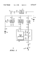
- FIG. 1 illustrates in partial block form and partial schematic form, a portion of an air bag deployment system in accordance with an embodiment of the present invention
- FIG. 2 is a schematic diagram of a simplified embodiment for a drive limit controller shown in FIG. 1;
- FIG. 3 is a schematic diagram of a switch circuit for the air bag deployment system shown in FIG. 1.
- FIG. 1 is a block diagram of a portion of an air bag deployment system 10 in accordance with an embodiment of the present invention.
- a battery 12 provides a positive voltage of about twelve to fourteen volts at terminal 14 in the preferred embodiment. The negative terminal of battery 12 is connected to ground.
- Input terminal 18 of boost pump circuit 16 receives the voltage of about twelve to fourteen volts and provides a voltage of about twenty-four volts at output terminal 20.
- a capacitor 22 with a value in the range of five-hundred microfarads ( ⁇ f) to ten-thousand microfarads is connected between terminal 24 and ground.
- Terminal 24 receives a boost voltage generated by boost pump circuit 16 at terminal 20 and stores that boost voltage on capacitor 22 (the opposite side of which is coupled to electrical ground).
- Terminal 28 of mechanical arm 26, terminal 34 of voltage monitor 32, terminal 40 of switch circuit 38 and the collector of NPN transistor 46 are connected to terminal 20 of boost pump circuit 16.
- Transistor 46 is a three-terminal semiconductor device with a base, a collector as a conducting electrode, and an emitter as a conducting electrode.
- Terminal 36 of voltage monitor 32 and terminal 50 of capacitor 48 are connected to the emitter of transistor 46.
- Capacitor 48 is connected between terminal 50 and ground.
- Terminal 44 of switch circuit 38 is connected to the base of transistor 46.
- Terminal 41 of switch circuit 38 is coupled for receiving a diagnostic check signal DISABLE.
- Terminal 43 of switch circuit 38 is coupled for receiving a signal NBIAS.
- High side current circuit 52 of FIG. 1 comprises drive limit controller 54, N-channel Metal Oxide Semiconductor (MOS) device 68, and resistor 70.
- Terminal 56 of drive limit controller 54 is coupled to terminal 50 for receiving a Charged Gate Drive (CGD) voltage of about twenty to thirty volts in the preferred embodiment.
- Terminal 58 of drive limit controller 54 provides a variable voltage output to the gate of MOS device 68 when the air bag is deployed.
- the drain of MOS device 68 is connected to output terminal 60 of high side current circuit 52.
- Terminal 60 receives a voltage from terminal 30 of mechanical arm 26 that indicates the air bag should be deployed.
- Resistor 70 is connected across terminals 64 and 66 of drive limit controller 54 and in series with MOS device 68.
- the source of MOS device 68 is coupled to terminal 64.
- Terminal 66 of drive limit controller 54 is connected to terminal 72 of high side current circuit 52.
- Squib 74 is a low resistive wire with a first terminal connected to terminal 72 of high side current circuit 52.
- the second terminal of squib 74 is connected to the drain of MOS device 76.
- the gate of MOS device 76 is connected to terminal 78 and the source of MOS device 76 is connected to ground.
- FIG. 2 is a schematic diagram of an embodiment for drive limit controller 54 shown in FIG. 1.
- a current source 82 is connected between terminal 56 and the collector of NPN transistor 84.
- a current source 88 is connected between terminal 56 and the collector of NPN transistor 86.
- the common bases of the transistors 84 and 86 are connected to the collector of transistor 86, thus forming a current mirror for transistors 84 and 86.
- the emitter of transistor 84 and the emitter of transistor 86 are connected to terminals 66 and 64, respectfully, of drive limit controller 54.
- drive limit controller 54 could be a current source connected between terminal 56 and terminal 58 should current limiting not be required for MOS device 68 during air bag deployment.
- FIG. 3 is a schematic diagram of switch circuit 38 for the air bag deployment system shown in FIG. 1.
- the gate of N-channel MOS device 92 is connected to terminal 41. Terminal 41 receives a signal DISABLE for diagnostic purposes.
- MOS device 92 has the source connected to ground and the drain connected to the source of MOS device 94, forming a node for terminal 44. Terminal 44 is coupled for providing a signal to the base of transistor 46 (see FIG. 1).
- the common gates of P-channel MOS devices 94 and 96 are connected to the drain of MOS device 96.
- the sources for both MOS devices 94 and 96 are connected to terminal 40.
- the drain of N-channel MOS device 98 is connected to the drain of MOS device 96.
- the source of MOS device 98 is connected to the drain of N-channel MOS device 100.
- the source of MOS device 100 is connected to ground and the gate is connected to terminal 43.
- Inverter 102 has an input and an output, with the input connected to terminal 41 and the output connected to the gate of MOS device 98.
- an air bag deployment system 10 sets a current limit and regulates that current into squib 74 when deployment is initiated.
- the vehicle battery 12 provides a voltage of about twelve to fourteen volts that is increased to about twenty to thirty volts by boost pump circuit 16.
- Capacitor 22 stores the boosted charge for supplying the current of about 2.1 amps to fire squib 74 when the air bag (not shown) is to be deployed.
- the deployment of the air bag is typically in response to an accelerometer output monitored by a microprocessor (not shown) for evaluating the deceleration and determining if a crash has occurred.
- Mechanical arm 26 safeguards the possibility that an inadvertent electrical connection could fire and cause deployment of the air bag.
- both high side MOS device 68 and low side MOS device 76 conduct current through the current path activated by the closing of mechanical arm 26.
- current from capacitor 22 flows through mechanical arm 26, high side MOS device 68, resistor 70, squib 74, low side MOS device 76, and into ground.
- High side current circuit 52 shown in FIG. 1 is powered by the electrically stored charge on capacitor 48.
- Resistor 70 monitors the current of about 2.1 amps conducting through squib 74 for modulating the gate voltage of MOS device 68.
- Drive limit controller 54 provides a variable gate voltage of about eighteen volts to high side MOS device 68, such that MOS device 68 functions as a current source in maintaining a relatively constant current of about 2.1 amps to squib 74 in the preferred embodiment.
- the embodiment shown in FIG. 2 for drive limit controller 54 provides a current source 82 with a current of about eight microamps into the collector of transistor 84.
- Current source 88 provides a current of about one microamp into the collector of transistor 86.
- the current limit to squib 74 is provided in accordance with the following equation in the preferred embodiment:
- I82 is the current supplied by current source 82
- I88 is the current supplied by current source 88
- V(R70) is the voltage across resistor 70 at terminals 64 and 66.
- a voltage is provided from the drain of transistor 84 to the gate of MOS device 68 for regulating the drain-to-source conduction current of power MOS device 68 at about 2.1 amps in the preferred embodiment.
- the voltage across resistor 70 summed with the base-emitter voltage (Vbe) for transistor 86 matches the Vbe for transistor 84 in the current mirror when in current regulation.
- MOS device 68 when the conduction current of MOS device 68 changes about a value, such as 2.0 amps, the current change in serially connected resistor 70 causes a voltage change across resistor 70.
- An increased current will increase the voltage at terminal 64 which when combined with the Vbe for transistor 86 provides for an increased Vbe for transistor 84.
- the voltage at the collector of transistor 84 decreases in accordance with the increased Vbe for transistor 84.
- the gate of MOS device 68 is connected to the collector of transistor 84, thus decreasing the gate-to-source voltage of MOS device 68.
- MOS device 68 an increasing conduction current above the 2.0 amps value in MOS device 68 is sensed in resistor 70 and the current mirror transistor 84 in drive limit controller 54 provides a decreasing gate voltage to MOS device 68, thus regulating the squib current to a value of about 2.0 amps.
- current sources 82 and 88 are supplied at terminal 56 with current stored in capacitor 48 (see FIG. 1) while squib 74 is supplied with current stored in capacitor 22.
- capacitor 48 provides about one microamp of current to current source 88 and about eight microamps of current to current source 82 while capacitor 22 provides a current of about 2.1 amps to squib 74.
- the separate storage capacitor 48 maintains a voltage in the range of eighteen to twenty four volts during deployment of the air bag compared with the voltage on capacitor 22 starting at about twenty-four volts and dropping to about ten volts.
- providing a separate capacitor 48 for supplying energy to drive limit controller 54 allows for the generation of a voltage for driving the gate of MOS device 68 such that a relatively constant current of about 2.1 amps is maintained for squib 74 during air bag deployment.
- capacitor 22 connected at terminal 24 is coupled to capacitor 48 connected at terminal 50 through NPN transistor 46.
- switch circuit 38 keeps transistor 46 conducting current such that the gate drive capacitor 48 is charged to about the same voltage as capacitor 22, i.e. twenty-four volts.
- Diagnostic checks disable the charging of capacitor 48 from capacitor 22 through transistor 46, or generate an isolation path of capacitor 48 from capacitor 22. While isolated, the voltage across capacitor 48 can be monitored to be above a minimal value of about 18 volts.
- the voltage across capacitor 48 remains relatively constant during the two milliseconds of time for air bag deployment in accordance with the small currents supplied from capacitor 48 to drive limit controller 54. During air bag deployment transistor 46 becomes reverse biased, thus blocking a conductive path between capacitors 22 and 48.
- An alternate embodiment for air bag deployment system 10, as shown in FIG. 1, would replace transistor 46 with a PN-diode (not shown) and also functionally eliminate switch circuit 38.
- the PN-diode would be connected such that the P-side of the diode is connected to terminal 24 and the N-side of the diode is connected to terminal 50.
- the diode is forward biased during normal operation and capacitor 48 is charged by capacitor 22.
- capacitor 22 discharges such that the diode becomes reversed biased.
- Switch circuit 38 in FIG. 3 functions in the following way.
- MOS device 92 When the input signal DISABLE at terminal 41 is high, MOS device 92 is conducting such that the voltage at terminal 44 is about zero volts. A gate voltage with the value of zero volts turns off transistor 46 (see FIG. 1), thus preventing an electrical conduction path between capacitor 22 and capacitor 48.
- the input signal DISABLE is high during diagnostic checks for determining the voltages on capacitors 22 and 48.
- MOS devices 96, 98, and 100 connected serially are conducting about twenty-five microamps of current.
- MOS device 94 is sized with a channel width about twenty times greater than the channel width for MOS device 96 in the preferred embodiment, such that M0S device 94 is conducting about four-hundred microamps of current.
- the approximate four-hundred microamps of current supplied by MOS device 94 is the base current into terminal 44 such that transistor 46 (see FIG. 1) provides the electrical conduction path allowing capacitor 48 to be charged from capacitor 22. In standby or normal operation, capacitor 48 is charged to a voltage of about twenty to thirty volts in preparation for the discharge of the air bag.
- a capacitor 48 separate from capacitor 22 that supplies energy for firing the squib, powers circuitry in drive limit controller 54 providing a variable voltage drive to MOS device 68 for regulating current at about 2.1 amps for firing the squib.
- Switch circuit 38 supplies gate current to transistor 46 such that an electrical connecting path allows capacitor 22 to charge capacitor 48. The charge stored on capacitor 48 is monitored through diagnostic checks to assure readiness to fire and operability.
- Switch circuit 38 also provides electrical isolation between capacitors 22 and 48 such that the voltage to drive limit controller 54 remains above eighteen volts during air bag deployment.
- An integrated circuit suitable for manufacture can be built to include boost pump circuit 16, voltage monitor 32, switch circuit 38, transistor 46, and drive limit controller 54.
- one embodiment has capacitors 22 and 48 supplying two loops of high side current circuit 52 for potentially firing two squibs 74 and deploying two air bags.
- air bag deployment system 10 could power high side current circuit 52 in a single loop system and fire a single squib 74 and deploy a single air bag.
- squib firing currents below the 2.1 amps are anticipated.
Landscapes
- Engineering & Computer Science (AREA)
- Mechanical Engineering (AREA)
- Air Bags (AREA)
Priority Applications (6)
| Application Number | Priority Date | Filing Date | Title |
|---|---|---|---|
| US08/674,067 US5734317A (en) | 1996-07-01 | 1996-07-01 | Current limit controller for an air bag deployment system |
| DE69716349T DE69716349T2 (de) | 1996-07-01 | 1997-06-25 | Regelschaltung zur Strombegrenzung für eine Airbag- Entfaltungsanordnung |
| EP97110374A EP0816186B1 (en) | 1996-07-01 | 1997-06-25 | Current limit controller for an air bag deployment system |
| JP18771797A JP3913321B2 (ja) | 1996-07-01 | 1997-06-26 | エア・バッグ拡張システム用限流制御装置 |
| CN97114012A CN1088015C (zh) | 1996-07-01 | 1997-06-27 | 用于气囊胀开的导电通路、系统及集成电路 |
| KR1019970030476A KR100507516B1 (ko) | 1996-07-01 | 1997-07-01 | 에어 백 전개 시스템, 에어 백 전개 시스템을 위한 전기적 도전 경로 및 집적 회로 |
Applications Claiming Priority (1)
| Application Number | Priority Date | Filing Date | Title |
|---|---|---|---|
| US08/674,067 US5734317A (en) | 1996-07-01 | 1996-07-01 | Current limit controller for an air bag deployment system |
Publications (1)
| Publication Number | Publication Date |
|---|---|
| US5734317A true US5734317A (en) | 1998-03-31 |
Family
ID=24705180
Family Applications (1)
| Application Number | Title | Priority Date | Filing Date |
|---|---|---|---|
| US08/674,067 Expired - Lifetime US5734317A (en) | 1996-07-01 | 1996-07-01 | Current limit controller for an air bag deployment system |
Country Status (6)
| Country | Link |
|---|---|
| US (1) | US5734317A (ko) |
| EP (1) | EP0816186B1 (ko) |
| JP (1) | JP3913321B2 (ko) |
| KR (1) | KR100507516B1 (ko) |
| CN (1) | CN1088015C (ko) |
| DE (1) | DE69716349T2 (ko) |
Cited By (12)
| Publication number | Priority date | Publication date | Assignee | Title |
|---|---|---|---|---|
| US5936313A (en) * | 1997-08-06 | 1999-08-10 | Siemens Automotive Corp. | Switched capacitor circuit for firing vehicle airbag squibs |
| US5977651A (en) * | 1996-06-05 | 1999-11-02 | Denso Corporation | Drive circuit for vehicle occupant safety apparatus |
| US6037674A (en) * | 1998-06-26 | 2000-03-14 | Motorola, Inc. | Circuit and method of current limiting a half-bridge driver |
| US6114777A (en) * | 1996-09-19 | 2000-09-05 | Siemens Aktiengesellschaft | Circuit configuration for current limiting in a protection system, in particular airbag control system |
| US6512308B2 (en) * | 2000-04-19 | 2003-01-28 | Koninklijke Philips Electronics N.V. | Fault tolerant air bag bus system without transformer |
| US20040108698A1 (en) * | 2002-11-26 | 2004-06-10 | Hubert Rothleitner | Drive circuit for a firing cap of a vehicle restraint system |
| US20050225924A1 (en) * | 2004-03-30 | 2005-10-13 | Dialog Semiconductor Gmbh | Squib driver for airbag application |
| US20050225925A1 (en) * | 2004-03-30 | 2005-10-13 | Dialog Semiconductor Gmbh | Low cost squib driver for airbag application |
| US20050231127A1 (en) * | 2004-03-30 | 2005-10-20 | Isao Yamamoto | Boost controller capable of step-up ratio control |
| US20070103001A1 (en) * | 2005-09-30 | 2007-05-10 | Giorgio Chiozzi | Power Switch Circuit for Driving an Airbag Squib Module |
| CN102681531A (zh) * | 2012-05-10 | 2012-09-19 | 四川金网通电子科技有限公司 | 一种实现电机控制器限流电流值自校准的方法 |
| US20150075401A1 (en) * | 2013-09-18 | 2015-03-19 | Freescale Semiconductor, Inc. | Squib driver diagnostic circuit and method |
Families Citing this family (6)
| Publication number | Priority date | Publication date | Assignee | Title |
|---|---|---|---|---|
| WO1999044867A1 (de) * | 1998-03-07 | 1999-09-10 | Temic Telefunken Microelectronic Gmbh | Verfahren zum betrieb einer insassensicherheitseinrichtung sowie ansteuereinheit |
| JP4668889B2 (ja) * | 2006-12-01 | 2011-04-13 | 日本化薬株式会社 | 点火素子搭載コンデンサ、ヘッダーアッシー、スクイブならびにエアバッグ用ガス発生装置およびシートベルトプリテンショナー用ガス発生装置 |
| EP2155521B1 (en) * | 2007-05-11 | 2014-07-09 | Freescale Semiconductor, Inc. | Digital squib driver circuit |
| WO2009058054A1 (en) * | 2007-10-29 | 2009-05-07 | Autoliv Development Ab | A backup power supply arrangement to a deployment circuit for triggering the activation of an occupant restraint system |
| DE102007055123B4 (de) * | 2007-11-19 | 2020-06-18 | Robert Bosch Gmbh | Steuergerät und Verfahren zur Ansteuerung von Personenschutzmitteln für ein Fahrzeug |
| US10014716B2 (en) * | 2015-12-22 | 2018-07-03 | Robert Bosch Gmbh | Discrete energy reservoir with diagnostics |
Citations (9)
| Publication number | Priority date | Publication date | Assignee | Title |
|---|---|---|---|---|
| US4933570A (en) * | 1987-02-24 | 1990-06-12 | Siemens Aktiengesellschaft | Circuit arrangement for triggering a safety system |
| US5101192A (en) * | 1989-07-11 | 1992-03-31 | Diesel Kiki Co., Ltd. | System for controlling activation of air bag for vehicle |
| US5155376A (en) * | 1989-06-15 | 1992-10-13 | Diesel Kiki Co., Ltd. | Vehicle safety device actuating circuit with monitoring current regulator |
| US5181011A (en) * | 1990-08-14 | 1993-01-19 | Zexel Corporation | Method for checking the operability of safety system for vehicles |
| US5194755A (en) * | 1991-03-04 | 1993-03-16 | Ford Motor Company | Airbag triggering system |
| US5234228A (en) * | 1991-02-12 | 1993-08-10 | Honda Giken Kogyo Kabushiki Kaisha | Air bag apparatus |
| US5309030A (en) * | 1992-10-19 | 1994-05-03 | Delco Electronics Corporation | Current source for a supplemental inflatable restraint system |
| US5432385A (en) * | 1993-03-18 | 1995-07-11 | Delco Electronics Corp. | Supplemental inflatable restraint energy management and deployment system |
| US5554890A (en) * | 1993-03-16 | 1996-09-10 | Fujitsu Ten Limited | Ignition circuit for a squib in an air bag in a vehicle |
Family Cites Families (6)
| Publication number | Priority date | Publication date | Assignee | Title |
|---|---|---|---|---|
| DE3506487A1 (de) * | 1985-02-23 | 1986-09-04 | Daimler-Benz Ag, 7000 Stuttgart | Spannungsversorgungseinrichtung fuer eine insassenschutzvorrichtung in einem fahrzeug |
| DE3626601A1 (de) * | 1986-08-06 | 1988-02-18 | Bosch Gmbh Robert | Sicherheitseinrichtung fuer fahrzeuginsassen |
| JPH04500147A (ja) * | 1988-08-17 | 1992-01-09 | ローベルト・ボッシュ・ゲゼルシャフト・ミット・ベシュレンクテル・ハフツング | エネルギー蓄積装置を充電するための変圧装置 |
| JP2510326B2 (ja) * | 1990-04-18 | 1996-06-26 | 日本電装株式会社 | エアバッグ作動装置 |
| DE4313124A1 (de) * | 1993-04-22 | 1994-10-27 | Bosch Gmbh Robert | Steuerschaltung für Zündpillen umfassende Zündkreise |
| JPH0781515A (ja) * | 1993-09-14 | 1995-03-28 | Nippondenso Co Ltd | 車両用乗員保護装置 |
-
1996
- 1996-07-01 US US08/674,067 patent/US5734317A/en not_active Expired - Lifetime
-
1997
- 1997-06-25 EP EP97110374A patent/EP0816186B1/en not_active Expired - Lifetime
- 1997-06-25 DE DE69716349T patent/DE69716349T2/de not_active Expired - Lifetime
- 1997-06-26 JP JP18771797A patent/JP3913321B2/ja not_active Expired - Lifetime
- 1997-06-27 CN CN97114012A patent/CN1088015C/zh not_active Expired - Lifetime
- 1997-07-01 KR KR1019970030476A patent/KR100507516B1/ko not_active IP Right Cessation
Patent Citations (9)
| Publication number | Priority date | Publication date | Assignee | Title |
|---|---|---|---|---|
| US4933570A (en) * | 1987-02-24 | 1990-06-12 | Siemens Aktiengesellschaft | Circuit arrangement for triggering a safety system |
| US5155376A (en) * | 1989-06-15 | 1992-10-13 | Diesel Kiki Co., Ltd. | Vehicle safety device actuating circuit with monitoring current regulator |
| US5101192A (en) * | 1989-07-11 | 1992-03-31 | Diesel Kiki Co., Ltd. | System for controlling activation of air bag for vehicle |
| US5181011A (en) * | 1990-08-14 | 1993-01-19 | Zexel Corporation | Method for checking the operability of safety system for vehicles |
| US5234228A (en) * | 1991-02-12 | 1993-08-10 | Honda Giken Kogyo Kabushiki Kaisha | Air bag apparatus |
| US5194755A (en) * | 1991-03-04 | 1993-03-16 | Ford Motor Company | Airbag triggering system |
| US5309030A (en) * | 1992-10-19 | 1994-05-03 | Delco Electronics Corporation | Current source for a supplemental inflatable restraint system |
| US5554890A (en) * | 1993-03-16 | 1996-09-10 | Fujitsu Ten Limited | Ignition circuit for a squib in an air bag in a vehicle |
| US5432385A (en) * | 1993-03-18 | 1995-07-11 | Delco Electronics Corp. | Supplemental inflatable restraint energy management and deployment system |
Cited By (19)
| Publication number | Priority date | Publication date | Assignee | Title |
|---|---|---|---|---|
| US5977651A (en) * | 1996-06-05 | 1999-11-02 | Denso Corporation | Drive circuit for vehicle occupant safety apparatus |
| US6114777A (en) * | 1996-09-19 | 2000-09-05 | Siemens Aktiengesellschaft | Circuit configuration for current limiting in a protection system, in particular airbag control system |
| US5936313A (en) * | 1997-08-06 | 1999-08-10 | Siemens Automotive Corp. | Switched capacitor circuit for firing vehicle airbag squibs |
| US6037674A (en) * | 1998-06-26 | 2000-03-14 | Motorola, Inc. | Circuit and method of current limiting a half-bridge driver |
| US6512308B2 (en) * | 2000-04-19 | 2003-01-28 | Koninklijke Philips Electronics N.V. | Fault tolerant air bag bus system without transformer |
| US20040108698A1 (en) * | 2002-11-26 | 2004-06-10 | Hubert Rothleitner | Drive circuit for a firing cap of a vehicle restraint system |
| US7209819B2 (en) * | 2002-11-26 | 2007-04-24 | Infineon Technologies Ag | Drive circuit for a firing cap of a vehicle restraint system |
| US20050231127A1 (en) * | 2004-03-30 | 2005-10-20 | Isao Yamamoto | Boost controller capable of step-up ratio control |
| US20050225925A1 (en) * | 2004-03-30 | 2005-10-13 | Dialog Semiconductor Gmbh | Low cost squib driver for airbag application |
| US7142407B2 (en) * | 2004-03-30 | 2006-11-28 | Dialog Semiconductor Gmbh | Squib driver for airbag application |
| US7154733B2 (en) * | 2004-03-30 | 2006-12-26 | Dialog Semiconductor Gmbh | Low cost squib driver for airbag application |
| US20050225924A1 (en) * | 2004-03-30 | 2005-10-13 | Dialog Semiconductor Gmbh | Squib driver for airbag application |
| US7307385B2 (en) * | 2004-03-30 | 2007-12-11 | Rohm Co., Ltd. | Boost controller capable of step-up ratio control |
| US20070103001A1 (en) * | 2005-09-30 | 2007-05-10 | Giorgio Chiozzi | Power Switch Circuit for Driving an Airbag Squib Module |
| US7932622B2 (en) | 2005-09-30 | 2011-04-26 | Infineon Technologies Ag | Power switch circuit for driving an airbag squib module |
| CN102681531A (zh) * | 2012-05-10 | 2012-09-19 | 四川金网通电子科技有限公司 | 一种实现电机控制器限流电流值自校准的方法 |
| CN102681531B (zh) * | 2012-05-10 | 2014-02-05 | 四川金网通电子科技有限公司 | 一种实现电机控制器限流电流值自校准的方法 |
| US20150075401A1 (en) * | 2013-09-18 | 2015-03-19 | Freescale Semiconductor, Inc. | Squib driver diagnostic circuit and method |
| US9139155B2 (en) * | 2013-09-18 | 2015-09-22 | Freescale Semiconductor, Inc. | Squib driver diagnostic circuit and method |
Also Published As
| Publication number | Publication date |
|---|---|
| DE69716349D1 (de) | 2002-11-21 |
| JP3913321B2 (ja) | 2007-05-09 |
| CN1175522A (zh) | 1998-03-11 |
| EP0816186B1 (en) | 2002-10-16 |
| KR100507516B1 (ko) | 2005-10-21 |
| KR980008874A (ko) | 1998-04-30 |
| JPH1067296A (ja) | 1998-03-10 |
| DE69716349T2 (de) | 2003-03-20 |
| EP0816186A1 (en) | 1998-01-07 |
| CN1088015C (zh) | 2002-07-24 |
Similar Documents
| Publication | Publication Date | Title |
|---|---|---|
| US5734317A (en) | Current limit controller for an air bag deployment system | |
| EP1769974B1 (en) | Power switch circuit for driving an airbag squib module | |
| US5596497A (en) | Control circuit for vehicle safety device | |
| JP3090037B2 (ja) | 車両用乗員保護装置 | |
| US6677734B2 (en) | Non-inverting dual voltage regulation set point power supply using a single inductor for restraint control module | |
| US5977651A (en) | Drive circuit for vehicle occupant safety apparatus | |
| US5135254A (en) | Vehicle air bag apparatus | |
| US11208067B2 (en) | Airbag control device and semiconductor device | |
| EP0615886A1 (en) | Supplemental inflatable restraint system | |
| US5420790A (en) | Energy reserve circuit for supplemental inflatable restraint | |
| JPH0626957B2 (ja) | 車両の乗客保護装置用給電装置 | |
| US5309030A (en) | Current source for a supplemental inflatable restraint system | |
| US20050225924A1 (en) | Squib driver for airbag application | |
| EP3715998A1 (en) | A voltage regulator circuit and corresponding method | |
| US5861681A (en) | Occupant crash protection device for a vehicle | |
| US7940513B2 (en) | Switch arrangement, integrated circuit, activation system | |
| US5701038A (en) | Current feedback control of AC deployment current for supplemental inflatable restraints | |
| EP0733960A2 (en) | Precision current limit circuit | |
| WO1990002440A1 (en) | Voltage transformer for charging energy stores | |
| JP3289620B2 (ja) | エアバッグシステム及びその診断方法 | |
| JP4223741B2 (ja) | 充電回路 | |
| KR100513081B1 (ko) | 에어백 컨트롤러용 전원 | |
| JPH08275511A (ja) | 昇圧装置 | |
| JPH06321052A (ja) | 車両用安全システムのための電源装置 | |
| JPH10278726A (ja) | 乗員保護装置 |
Legal Events
| Date | Code | Title | Description |
|---|---|---|---|
| AS | Assignment |
Owner name: MOTOROLA, INC., ILLINOIS Free format text: ASSIGNMENT OF ASSIGNORS INTEREST;ASSIGNORS:BENNETT, PAUL T.;GRAY, RANDALL C.;REEL/FRAME:008080/0712 Effective date: 19960624 |
|
| STCF | Information on status: patent grant |
Free format text: PATENTED CASE |
|
| FPAY | Fee payment |
Year of fee payment: 4 |
|
| AS | Assignment |
Owner name: FREESCALE SEMICONDUCTOR, INC., TEXAS Free format text: ASSIGNMENT OF ASSIGNORS INTEREST;ASSIGNOR:MOTOROLA, INC.;REEL/FRAME:015698/0657 Effective date: 20040404 Owner name: FREESCALE SEMICONDUCTOR, INC.,TEXAS Free format text: ASSIGNMENT OF ASSIGNORS INTEREST;ASSIGNOR:MOTOROLA, INC.;REEL/FRAME:015698/0657 Effective date: 20040404 |
|
| FPAY | Fee payment |
Year of fee payment: 8 |
|
| AS | Assignment |
Owner name: CITIBANK, N.A. AS COLLATERAL AGENT, NEW YORK Free format text: SECURITY AGREEMENT;ASSIGNORS:FREESCALE SEMICONDUCTOR, INC.;FREESCALE ACQUISITION CORPORATION;FREESCALE ACQUISITION HOLDINGS CORP.;AND OTHERS;REEL/FRAME:018855/0129 Effective date: 20061201 Owner name: CITIBANK, N.A. AS COLLATERAL AGENT,NEW YORK Free format text: SECURITY AGREEMENT;ASSIGNORS:FREESCALE SEMICONDUCTOR, INC.;FREESCALE ACQUISITION CORPORATION;FREESCALE ACQUISITION HOLDINGS CORP.;AND OTHERS;REEL/FRAME:018855/0129 Effective date: 20061201 |
|
| FPAY | Fee payment |
Year of fee payment: 12 |
|
| AS | Assignment |
Owner name: CITIBANK, N.A., AS COLLATERAL AGENT,NEW YORK Free format text: SECURITY AGREEMENT;ASSIGNOR:FREESCALE SEMICONDUCTOR, INC.;REEL/FRAME:024397/0001 Effective date: 20100413 Owner name: CITIBANK, N.A., AS COLLATERAL AGENT, NEW YORK Free format text: SECURITY AGREEMENT;ASSIGNOR:FREESCALE SEMICONDUCTOR, INC.;REEL/FRAME:024397/0001 Effective date: 20100413 |
|
| AS | Assignment |
Owner name: CITIBANK, N.A., AS NOTES COLLATERAL AGENT, NEW YOR Free format text: SECURITY AGREEMENT;ASSIGNOR:FREESCALE SEMICONDUCTOR, INC.;REEL/FRAME:030633/0424 Effective date: 20130521 |
|
| AS | Assignment |
Owner name: CITIBANK, N.A., AS NOTES COLLATERAL AGENT, NEW YOR Free format text: SECURITY AGREEMENT;ASSIGNOR:FREESCALE SEMICONDUCTOR, INC.;REEL/FRAME:031591/0266 Effective date: 20131101 |
|
| AS | Assignment |
Owner name: FREESCALE SEMICONDUCTOR, INC., TEXAS Free format text: PATENT RELEASE;ASSIGNOR:CITIBANK, N.A., AS COLLATERAL AGENT;REEL/FRAME:037354/0225 Effective date: 20151207 Owner name: FREESCALE SEMICONDUCTOR, INC., TEXAS Free format text: PATENT RELEASE;ASSIGNOR:CITIBANK, N.A., AS COLLATERAL AGENT;REEL/FRAME:037356/0143 Effective date: 20151207 Owner name: FREESCALE SEMICONDUCTOR, INC., TEXAS Free format text: PATENT RELEASE;ASSIGNOR:CITIBANK, N.A., AS COLLATERAL AGENT;REEL/FRAME:037356/0553 Effective date: 20151207 |
|
| AS | Assignment |
Owner name: MORGAN STANLEY SENIOR FUNDING, INC., MARYLAND Free format text: ASSIGNMENT AND ASSUMPTION OF SECURITY INTEREST IN PATENTS;ASSIGNOR:CITIBANK, N.A.;REEL/FRAME:037486/0517 Effective date: 20151207 |
|
| AS | Assignment |
Owner name: MORGAN STANLEY SENIOR FUNDING, INC., MARYLAND Free format text: ASSIGNMENT AND ASSUMPTION OF SECURITY INTEREST IN PATENTS;ASSIGNOR:CITIBANK, N.A.;REEL/FRAME:037518/0292 Effective date: 20151207 |
|
| AS | Assignment |
Owner name: MORGAN STANLEY SENIOR FUNDING, INC., MARYLAND Free format text: SUPPLEMENT TO THE SECURITY AGREEMENT;ASSIGNOR:FREESCALE SEMICONDUCTOR, INC.;REEL/FRAME:039138/0001 Effective date: 20160525 |
|
| AS | Assignment |
Owner name: NXP, B.V., F/K/A FREESCALE SEMICONDUCTOR, INC., NETHERLANDS Free format text: RELEASE BY SECURED PARTY;ASSIGNOR:MORGAN STANLEY SENIOR FUNDING, INC.;REEL/FRAME:040925/0001 Effective date: 20160912 Owner name: NXP, B.V., F/K/A FREESCALE SEMICONDUCTOR, INC., NE Free format text: RELEASE BY SECURED PARTY;ASSIGNOR:MORGAN STANLEY SENIOR FUNDING, INC.;REEL/FRAME:040925/0001 Effective date: 20160912 |
|
| AS | Assignment |
Owner name: NXP B.V., NETHERLANDS Free format text: RELEASE BY SECURED PARTY;ASSIGNOR:MORGAN STANLEY SENIOR FUNDING, INC.;REEL/FRAME:040928/0001 Effective date: 20160622 |
|
| AS | Assignment |
Owner name: MORGAN STANLEY SENIOR FUNDING, INC., MARYLAND Free format text: CORRECTIVE ASSIGNMENT TO CORRECT THE REMOVE PATENTS 8108266 AND 8062324 AND REPLACE THEM WITH 6108266 AND 8060324 PREVIOUSLY RECORDED ON REEL 037518 FRAME 0292. ASSIGNOR(S) HEREBY CONFIRMS THE ASSIGNMENT AND ASSUMPTION OF SECURITY INTEREST IN PATENTS;ASSIGNOR:CITIBANK, N.A.;REEL/FRAME:041703/0536 Effective date: 20151207 |
|
| AS | Assignment |
Owner name: SHENZHEN XINGUODU TECHNOLOGY CO., LTD., CHINA Free format text: CORRECTIVE ASSIGNMENT TO CORRECT THE TO CORRECT THE APPLICATION NO. FROM 13,883,290 TO 13,833,290 PREVIOUSLY RECORDED ON REEL 041703 FRAME 0536. ASSIGNOR(S) HEREBY CONFIRMS THE THE ASSIGNMENT AND ASSUMPTION OF SECURITYINTEREST IN PATENTS.;ASSIGNOR:MORGAN STANLEY SENIOR FUNDING, INC.;REEL/FRAME:048734/0001 Effective date: 20190217 |
|
| AS | Assignment |
Owner name: NXP B.V., NETHERLANDS Free format text: RELEASE BY SECURED PARTY;ASSIGNOR:MORGAN STANLEY SENIOR FUNDING, INC.;REEL/FRAME:050744/0097 Effective date: 20190903 |
|
| AS | Assignment |
Owner name: MORGAN STANLEY SENIOR FUNDING, INC., MARYLAND Free format text: CORRECTIVE ASSIGNMENT TO CORRECT THE REMOVE APPLICATION11759915 AND REPLACE IT WITH APPLICATION 11759935 PREVIOUSLY RECORDED ON REEL 037486 FRAME 0517. ASSIGNOR(S) HEREBY CONFIRMS THE ASSIGNMENT AND ASSUMPTION OF SECURITYINTEREST IN PATENTS;ASSIGNOR:CITIBANK, N.A.;REEL/FRAME:053547/0421 Effective date: 20151207 |
|
| AS | Assignment |
Owner name: NXP B.V., NETHERLANDS Free format text: CORRECTIVE ASSIGNMENT TO CORRECT THE REMOVEAPPLICATION 11759915 AND REPLACE IT WITH APPLICATION11759935 PREVIOUSLY RECORDED ON REEL 040928 FRAME 0001. ASSIGNOR(S) HEREBY CONFIRMS THE RELEASE OF SECURITYINTEREST;ASSIGNOR:MORGAN STANLEY SENIOR FUNDING, INC.;REEL/FRAME:052915/0001 Effective date: 20160622 |
|
| AS | Assignment |
Owner name: NXP, B.V. F/K/A FREESCALE SEMICONDUCTOR, INC., NETHERLANDS Free format text: CORRECTIVE ASSIGNMENT TO CORRECT THE REMOVEAPPLICATION 11759915 AND REPLACE IT WITH APPLICATION11759935 PREVIOUSLY RECORDED ON REEL 040925 FRAME 0001. ASSIGNOR(S) HEREBY CONFIRMS THE RELEASE OF SECURITYINTEREST;ASSIGNOR:MORGAN STANLEY SENIOR FUNDING, INC.;REEL/FRAME:052917/0001 Effective date: 20160912 |