US5630306A - Insulating spacer for creating a thermally insulating bridge - Google Patents
Insulating spacer for creating a thermally insulating bridge Download PDFInfo
- Publication number
- US5630306A US5630306A US08/589,633 US58963396A US5630306A US 5630306 A US5630306 A US 5630306A US 58963396 A US58963396 A US 58963396A US 5630306 A US5630306 A US 5630306A
- Authority
- US
- United States
- Prior art keywords
- bridge member
- leg members
- extensions
- insulating spacer
- leg
- Prior art date
- Legal status (The legal status is an assumption and is not a legal conclusion. Google has not performed a legal analysis and makes no representation as to the accuracy of the status listed.)
- Expired - Lifetime
Links
- 125000006850 spacer group Chemical group 0.000 title claims abstract description 142
- 239000000463 material Substances 0.000 claims abstract description 101
- 229910052751 metal Inorganic materials 0.000 claims abstract description 48
- 239000002184 metal Substances 0.000 claims abstract description 48
- 229920003002 synthetic resin Polymers 0.000 claims abstract description 45
- 239000000057 synthetic resin Substances 0.000 claims abstract description 45
- 239000002131 composite material Substances 0.000 claims abstract description 40
- 238000000034 method Methods 0.000 claims abstract description 23
- 238000004519 manufacturing process Methods 0.000 claims description 27
- 238000010030 laminating Methods 0.000 claims description 15
- 229910052782 aluminium Inorganic materials 0.000 claims description 11
- 229910000831 Steel Inorganic materials 0.000 claims description 8
- XAGFODPZIPBFFR-UHFFFAOYSA-N aluminium Chemical compound [Al] XAGFODPZIPBFFR-UHFFFAOYSA-N 0.000 claims description 8
- 229920005644 polyethylene terephthalate glycol copolymer Polymers 0.000 claims description 8
- 239000010959 steel Substances 0.000 claims description 8
- 238000002844 melting Methods 0.000 claims description 7
- 230000008018 melting Effects 0.000 claims description 7
- 239000010935 stainless steel Substances 0.000 claims description 7
- 229910001220 stainless steel Inorganic materials 0.000 claims description 7
- 229910001335 Galvanized steel Inorganic materials 0.000 claims description 6
- 239000008397 galvanized steel Substances 0.000 claims description 6
- ATJFFYVFTNAWJD-UHFFFAOYSA-N Tin Chemical compound [Sn] ATJFFYVFTNAWJD-UHFFFAOYSA-N 0.000 claims description 5
- 229910052718 tin Inorganic materials 0.000 claims description 5
- 239000011135 tin Substances 0.000 claims description 5
- 239000011521 glass Substances 0.000 description 53
- 229920005989 resin Polymers 0.000 description 22
- 239000011347 resin Substances 0.000 description 22
- 229920003023 plastic Polymers 0.000 description 14
- 239000004033 plastic Substances 0.000 description 14
- 239000000565 sealant Substances 0.000 description 12
- 238000009833 condensation Methods 0.000 description 7
- 230000005494 condensation Effects 0.000 description 7
- 239000002274 desiccant Substances 0.000 description 7
- 238000010276 construction Methods 0.000 description 6
- 238000001816 cooling Methods 0.000 description 5
- 239000006260 foam Substances 0.000 description 5
- 239000004800 polyvinyl chloride Substances 0.000 description 5
- 238000003466 welding Methods 0.000 description 5
- 230000005540 biological transmission Effects 0.000 description 4
- -1 e.g. Substances 0.000 description 4
- 229920001021 polysulfide Polymers 0.000 description 4
- 239000005077 polysulfide Substances 0.000 description 4
- 150000008117 polysulfides Polymers 0.000 description 4
- 229920002635 polyurethane Polymers 0.000 description 4
- 239000004814 polyurethane Substances 0.000 description 4
- 229920000915 polyvinyl chloride Polymers 0.000 description 4
- 230000008569 process Effects 0.000 description 4
- 238000012546 transfer Methods 0.000 description 4
- XLYOFNOQVPJJNP-UHFFFAOYSA-N water Chemical compound O XLYOFNOQVPJJNP-UHFFFAOYSA-N 0.000 description 4
- 229920001634 Copolyester Polymers 0.000 description 3
- LYCAIKOWRPUZTN-UHFFFAOYSA-N Ethylene glycol Chemical compound OCCO LYCAIKOWRPUZTN-UHFFFAOYSA-N 0.000 description 3
- 238000001125 extrusion Methods 0.000 description 3
- 238000010438 heat treatment Methods 0.000 description 3
- 230000006698 induction Effects 0.000 description 3
- 238000009434 installation Methods 0.000 description 3
- 229920000139 polyethylene terephthalate Polymers 0.000 description 3
- 239000005020 polyethylene terephthalate Substances 0.000 description 3
- 229920002367 Polyisobutene Polymers 0.000 description 2
- ATUOYWHBWRKTHZ-UHFFFAOYSA-N Propane Chemical class CCC ATUOYWHBWRKTHZ-UHFFFAOYSA-N 0.000 description 2
- VYPSYNLAJGMNEJ-UHFFFAOYSA-N Silicium dioxide Chemical compound O=[Si]=O VYPSYNLAJGMNEJ-UHFFFAOYSA-N 0.000 description 2
- YIMQCDZDWXUDCA-UHFFFAOYSA-N [4-(hydroxymethyl)cyclohexyl]methanol Chemical compound OCC1CCC(CO)CC1 YIMQCDZDWXUDCA-UHFFFAOYSA-N 0.000 description 2
- 239000000853 adhesive Substances 0.000 description 2
- 230000001070 adhesive effect Effects 0.000 description 2
- 230000015572 biosynthetic process Effects 0.000 description 2
- 238000005266 casting Methods 0.000 description 2
- 239000011248 coating agent Substances 0.000 description 2
- 238000000576 coating method Methods 0.000 description 2
- 239000004020 conductor Substances 0.000 description 2
- 239000007789 gas Substances 0.000 description 2
- WGCNASOHLSPBMP-UHFFFAOYSA-N hydroxyacetaldehyde Natural products OCC=O WGCNASOHLSPBMP-UHFFFAOYSA-N 0.000 description 2
- 230000006872 improvement Effects 0.000 description 2
- 238000009413 insulation Methods 0.000 description 2
- 238000010943 off-gassing Methods 0.000 description 2
- 229920000642 polymer Polymers 0.000 description 2
- 238000000926 separation method Methods 0.000 description 2
- 229920001169 thermoplastic Polymers 0.000 description 2
- 239000004416 thermosoftening plastic Substances 0.000 description 2
- 238000011144 upstream manufacturing Methods 0.000 description 2
- 229920002554 vinyl polymer Polymers 0.000 description 2
- OMIHGPLIXGGMJB-UHFFFAOYSA-N 7-oxabicyclo[4.1.0]hepta-1,3,5-triene Chemical compound C1=CC=C2OC2=C1 OMIHGPLIXGGMJB-UHFFFAOYSA-N 0.000 description 1
- 229910000975 Carbon steel Inorganic materials 0.000 description 1
- ZAMOUSCENKQFHK-UHFFFAOYSA-N Chlorine atom Chemical compound [Cl] ZAMOUSCENKQFHK-UHFFFAOYSA-N 0.000 description 1
- 239000004677 Nylon Substances 0.000 description 1
- 230000009471 action Effects 0.000 description 1
- 238000004026 adhesive bonding Methods 0.000 description 1
- 230000004888 barrier function Effects 0.000 description 1
- 239000011324 bead Substances 0.000 description 1
- 238000005452 bending Methods 0.000 description 1
- 239000007767 bonding agent Substances 0.000 description 1
- 239000010962 carbon steel Substances 0.000 description 1
- 230000008859 change Effects 0.000 description 1
- 229910052801 chlorine Inorganic materials 0.000 description 1
- 239000000460 chlorine Substances 0.000 description 1
- 230000008602 contraction Effects 0.000 description 1
- 238000005336 cracking Methods 0.000 description 1
- 230000007423 decrease Effects 0.000 description 1
- 238000013461 design Methods 0.000 description 1
- 238000010586 diagram Methods 0.000 description 1
- 238000005553 drilling Methods 0.000 description 1
- 229920001971 elastomer Polymers 0.000 description 1
- 238000004134 energy conservation Methods 0.000 description 1
- 239000003000 extruded plastic Substances 0.000 description 1
- 238000005562 fading Methods 0.000 description 1
- 239000012467 final product Substances 0.000 description 1
- 239000006261 foam material Substances 0.000 description 1
- 239000000499 gel Substances 0.000 description 1
- 239000003365 glass fiber Substances 0.000 description 1
- 150000002334 glycols Chemical class 0.000 description 1
- 230000009931 harmful effect Effects 0.000 description 1
- 230000017525 heat dissipation Effects 0.000 description 1
- 238000001746 injection moulding Methods 0.000 description 1
- 238000005304 joining Methods 0.000 description 1
- 239000000155 melt Substances 0.000 description 1
- 150000002739 metals Chemical class 0.000 description 1
- 238000012986 modification Methods 0.000 description 1
- 230000004048 modification Effects 0.000 description 1
- 229910052755 nonmetal Inorganic materials 0.000 description 1
- 229920001778 nylon Polymers 0.000 description 1
- 238000004806 packaging method and process Methods 0.000 description 1
- 230000000149 penetrating effect Effects 0.000 description 1
- 230000035515 penetration Effects 0.000 description 1
- ISWSIDIOOBJBQZ-UHFFFAOYSA-N phenol group Chemical group C1(=CC=CC=C1)O ISWSIDIOOBJBQZ-UHFFFAOYSA-N 0.000 description 1
- 229920001568 phenolic resin Polymers 0.000 description 1
- 239000004014 plasticizer Substances 0.000 description 1
- 229920000515 polycarbonate Polymers 0.000 description 1
- 239000004417 polycarbonate Substances 0.000 description 1
- 229920005668 polycarbonate resin Polymers 0.000 description 1
- 239000004431 polycarbonate resin Substances 0.000 description 1
- 229920000728 polyester Polymers 0.000 description 1
- 229920001225 polyester resin Polymers 0.000 description 1
- 229920005749 polyurethane resin Polymers 0.000 description 1
- 238000012545 processing Methods 0.000 description 1
- 239000001294 propane Substances 0.000 description 1
- 238000004080 punching Methods 0.000 description 1
- 239000005060 rubber Substances 0.000 description 1
- 239000000377 silicon dioxide Substances 0.000 description 1
- 239000000243 solution Substances 0.000 description 1
- 238000001179 sorption measurement Methods 0.000 description 1
- KKEYFWRCBNTPAC-UHFFFAOYSA-L terephthalate(2-) Chemical compound [O-]C(=O)C1=CC=C(C([O-])=O)C=C1 KKEYFWRCBNTPAC-UHFFFAOYSA-L 0.000 description 1
- 229920005992 thermoplastic resin Polymers 0.000 description 1
- 125000000391 vinyl group Chemical group [H]C([*])=C([H])[H] 0.000 description 1
Images


Classifications
-
- E—FIXED CONSTRUCTIONS
- E06—DOORS, WINDOWS, SHUTTERS, OR ROLLER BLINDS IN GENERAL; LADDERS
- E06B—FIXED OR MOVABLE CLOSURES FOR OPENINGS IN BUILDINGS, VEHICLES, FENCES OR LIKE ENCLOSURES IN GENERAL, e.g. DOORS, WINDOWS, BLINDS, GATES
- E06B3/00—Window sashes, door leaves, or like elements for closing wall or like openings; Layout of fixed or moving closures, e.g. windows in wall or like openings; Features of rigidly-mounted outer frames relating to the mounting of wing frames
- E06B3/66—Units comprising two or more parallel glass or like panes permanently secured together
- E06B3/673—Assembling the units
- E06B3/67304—Preparing rigid spacer members before assembly
-
- E—FIXED CONSTRUCTIONS
- E06—DOORS, WINDOWS, SHUTTERS, OR ROLLER BLINDS IN GENERAL; LADDERS
- E06B—FIXED OR MOVABLE CLOSURES FOR OPENINGS IN BUILDINGS, VEHICLES, FENCES OR LIKE ENCLOSURES IN GENERAL, e.g. DOORS, WINDOWS, BLINDS, GATES
- E06B3/00—Window sashes, door leaves, or like elements for closing wall or like openings; Layout of fixed or moving closures, e.g. windows in wall or like openings; Features of rigidly-mounted outer frames relating to the mounting of wing frames
- E06B3/66—Units comprising two or more parallel glass or like panes permanently secured together
- E06B3/663—Elements for spacing panes
- E06B3/66309—Section members positioned at the edges of the glazing unit
- E06B3/66314—Section members positioned at the edges of the glazing unit of tubular shape
-
- E—FIXED CONSTRUCTIONS
- E06—DOORS, WINDOWS, SHUTTERS, OR ROLLER BLINDS IN GENERAL; LADDERS
- E06B—FIXED OR MOVABLE CLOSURES FOR OPENINGS IN BUILDINGS, VEHICLES, FENCES OR LIKE ENCLOSURES IN GENERAL, e.g. DOORS, WINDOWS, BLINDS, GATES
- E06B3/00—Window sashes, door leaves, or like elements for closing wall or like openings; Layout of fixed or moving closures, e.g. windows in wall or like openings; Features of rigidly-mounted outer frames relating to the mounting of wing frames
- E06B3/66—Units comprising two or more parallel glass or like panes permanently secured together
- E06B3/663—Elements for spacing panes
- E06B3/66309—Section members positioned at the edges of the glazing unit
- E06B3/66323—Section members positioned at the edges of the glazing unit comprising an interruption of the heat flow in a direction perpendicular to the unit
-
- Y—GENERAL TAGGING OF NEW TECHNOLOGICAL DEVELOPMENTS; GENERAL TAGGING OF CROSS-SECTIONAL TECHNOLOGIES SPANNING OVER SEVERAL SECTIONS OF THE IPC; TECHNICAL SUBJECTS COVERED BY FORMER USPC CROSS-REFERENCE ART COLLECTIONS [XRACs] AND DIGESTS
- Y10—TECHNICAL SUBJECTS COVERED BY FORMER USPC
- Y10T—TECHNICAL SUBJECTS COVERED BY FORMER US CLASSIFICATION
- Y10T29/00—Metal working
- Y10T29/49—Method of mechanical manufacture
- Y10T29/49616—Structural member making
- Y10T29/49623—Static structure, e.g., a building component
- Y10T29/49625—Openwork, e.g., a truss, joist, frame, lattice-type or box beam
Definitions
- This invention generally relates to an insulating spacer and in particular to an insulating spacer for creating a thermally insulating bridge between spaced-apart panes in a multiple glass window unit, for example, to improve the thermal insulation performance of the unit.
- This invention also relates to methods of making such an insulating spacer.
- all-plastic spacers particularly nylon, vinyl, polyvinyl chloride, polycarbonate or other extruded plastic spacers, but these units generally have been thin and structurally weak. In fact, these thin, non-metal spacers can bend undesirably and collapse. Furthermore, to date, most thermoplastics have been unacceptable for use as spacers because they give off volatile materials, e.g., plasticizers, which can cloud or fog the interior glass surface. In view of the above-noted drawbacks, such all-plastic spacers generally have been found unsatisfactory.
- metal has been the generally accepted material even though this material has a number of disadvantages.
- the thermal conductivity of metal is considerably higher than that of glass or of the air space between the panes of glass.
- heat from within a building tries to escape in winter, and it takes the path of least resistance.
- the path of least resistance is around the perimeter of a sealed window unit, where the metal spacer strip is provided.
- Metal spacers contacting the inner and outer panes of glass act as conductors between the panes and provide an easy path for the transmission of heat from the inside glass panel to the outside panel.
- condensation of moisture can occur inside the insulating glass or on the surfaces of the inner glass panel.
- heat is rapidly lost from around the perimeter of the window, often causing a ten to twenty degree Fahrenheit temperature drop at the perimeter of the window relative to the center thereof. Under extreme conditions in winter, a frost line can occur around the perimeter of the window unit.
- the above-noted temperature differential also results in differential shrinkage between the center of the glass pane and the perimeter. Then, stress cracks can develop in the glass or the seal can be broken. When the outside seal breaks down, air can enter the space between the windows carrying water vapor which is deposited inside the panes. Condensation of this moisture causes fogging of the window unit. Many window units tend to fail due to such stress cracks or loss of seal.
- a still further problem with conventional glass units is related to deflection of the panels under the influence of high winds, traffic noise, or internal pressure changes owing to expansion or contraction of the air mass contained within the glass unit. This action imposes high stresses on the glass panels and can break the seal between the spacer and the glass thus allowing moisture to enter. In extreme cases, the glass panels can break.
- Such a spacer provides advantages due to the structural rigidity provided by the metal base.
- the spacer suffers from disadvantages in that the relatively thin coating of foam material may not serve as a thermally insulating bridge over the continuous metal tube.
- such a spacer can be expensive to manufacture, because conventional injection molding techniques can be impractical to make such a thin hollow elongated body.
- vinyl spacers are generally poor sealants and are subject to mechanical failure.
- the present invention provides an improved thermally insulating spacer for a multiple glass unit which solves or overcomes the drawbacks noted above with respect to conventional and other insulated spacers.
- the present invention also can be a replacement for conventional aluminum spacers, for example.
- This invention thus keeps the inner pane of glass several degrees warmer than it might otherwise be in the winter, while preventing condensation that otherwise may occur.
- the present invention provides an insulating spacer for spacing apart panes of a multiple pane window unit, for example, and for defining an insulated space between the panes.
- the insulating spacer includes a top bridge member, a metallic first leg member and a metallic second leg member, a bottom bridge member and a channel portion defined by a configuration of the top bridge member, the first and second leg members and the bottom bridge member.
- the top bridge member is made from a synthetic resin material or composites thereof, and is provided for contacting the panes of the multiple pane unit and creating a thermally insulating bridge between the panes.
- the top bridge member has an upper surface and a lower surface substantially parallel to the upper surface, and can include openings.
- the channel portion can contain desiccant material for adsorbing moisture from the space between the window panes through the openings in the top bridge member.
- the bottom bridge member is roll-formed from the same piece of material as the first and second leg members.
- the bottom bridge member is formed from a synthetic resin or composite material the same as, or similar to, that of the top bridge member.
- the first and second leg members have extensions on both ends thereof. Portions of the bottom bridge member pass through the perforations in these extensions, to secure the leg members to the bottom bridge member.
- the present invention can be customized to a particular installation or to a customer's demand by extruding the outer sides of the top bridge member to the finished dimensions and by bending the first and second leg members to the desired dimensions.
- the first and second leg members provide structural rigidity and intended bendability in fabrication and allow the spacer to conform to and retain varying dimensions.
- the present invention improves the thermal performance of the insulated glass units along the edge of the assembly.
- the present invention also provides methods of making the insulating spacer of the present invention.
- One method includes the steps of: forming metal into first and second leg members, the first and second leg members having extensions on one end thereof, and the extensions of the first and second leg members being perforated, preheating the leg members near or above the melting point of a synthetic resin or composite material, forcing together the extensions of the first and second leg members of the channel and the one of the synthetic resin material and the composite synthetic resin material, to secure the extensions of the leg members to the material such that the material forms a first bridge member across the leg members, and defining a channel portion of an insulating spacer by the configuration of the first bridge member, the first and second leg members and a second bridge member.
- portions of the top bridge member pass through the perforations in the extensions of the leg members, to secure the leg members to the top bridge member.
- the present invention also includes other ways to secure the first and second leg members to the top bridge member, such as by cross head extrusion of the top bridge member, adhesive or otherwise bonding the elements together, or by ultrasonic vibration or heating.
- the first and second leg members can be bent into a desired configuration.
- the desired configuration can be zig-zag.
- FIGS. 1A and 1B are perspective views of alternate first embodiments of a double seal insulating spacer of the present invention.
- FIGS. 2A and 2B are perspective views of alternate second embodiments of a single seal insulating spacer of the present invention.
- FIGS. 3A and 3B are perspective views of alternate third embodiments of a double seal insulating spacer of the present invention.
- FIG. 4 shows an insulating spacer channel for use in the present invention.
- FIG. 5 is a schematic diagram of a method of making the insulating spacer of the present invention.
- the insulating spacer of the present invention is designed as a double seal insulating spacer for spacing apart panes of, for example, a double glass window unit (not shown) and for defining an insulated space between the panes.
- double pane glass window units For ease of discussion, reference is made herein to double pane glass window units.
- the present invention can be utilized with multiple pane units, and is not limited to window units made from glass, or even to window units. Rather, the present invention can be used with units made from plastic and other materials, and to doors, display cases and like applications where insulating spacers are required.
- the insulating spacer and methods of making same of the present invention are improvements over those disclosed in commonly assigned U.S. Pat. No. 5,313,762 and commonly assigned [copending application No. 08/189,145, filed Jan. 31, 1994, which will issue as] U.S. Pat. No. 5,485,709 [on Jan. 23, 1996,] the disclosures of each of which are incorporated herein by reference.
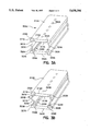
- a first embodiment of a double seal insulating spacer of the present invention is designated by reference numeral 100A.
- the spacer 100A includes a top bridge member 110A for contacting the inner and outer window panes of a double pane window unit, for instance.
- the top bridge member is made of synthetic resin materials capable of providing the desired physical characteristics and capable of withstanding ultraviolet light without fading or discoloring, such as polyethylene terephthalate resins, polycarbonate resins or other suitable synthetic resins, or from composites thereof including those of glass fibers or beads, for example.
- PETG available from Eastman or BASF is used.
- poly(ethylene-1,4-cyclohexylenedimethylene terephthalate) available from Eastman under the tradename Kodar PETG copolyester 6763, which is an amorphous (noncrystalline) thermoplastic polyester of the PET [poly(ethylene terephthalate)] family.
- the "G” in the Kodar PETG copolyester designation indicates the use of a second glycol(1,4-cyclohexanedimethanol, or CHDM) in making the polymer.
- CHDM 1,4-cyclohexanedimethanol
- PVC polyvinyl chloride
- the top bridge member 110A is of unitary construction and includes an upper surface 112A and a lower surface 114A substantially parallel to the upper surface 112A.
- the top bridge member 110A can include openings 160A.
- top bridge member 110A can be provided with a cavity, recess or trough portion to receive, for example, a frame to hold a decorative panel, to provide a triple pane arrangement. Also, top bridge member 110A can be punched or drilled, for example, to receive muntins or other decorative features.
- Channel member 120A includes first and second legs 122A and 124A, respectively.
- the first and second legs of the channel member 120A can be made of metal selected from the group consisting of stainless steel, galvanized steel, tin plated steel and aluminum, including composites thereof. Although stainless or galvanized steel is preferred, other metals can be used if desired.
- first leg 122A and second leg 124A are secured to the top bridge member 110A.
- first leg 122A includes an extension 130A
- second leg 124A includes an extension 132A.
- Extensions 130A and 132A are "inwardly extending" towards the center of spacer 100A. This is preferred, since the perforations thereof, discussed below, are contained “within” the spacer.
- first leg 122A and second leg 124A can be arranged flush with top bridge member 110A, rather than being recessed therefrom. Such an arrangement may be desired in warmer installations where large temperature gradients are not a factor.
- portions of the material of the top bridge member 110A pass through the perforations 131A and 133A of the extensions of the first and second legs 122A and 124A. I have found that these portions of the material passing through the perforations have a tendency to "grab" or "bite into” the metal on the other side, to assist in securing the elements together. In fact, the material passing through the perforations forms a mushroom-shaped rivet on the other side of the spacer.
- the extensions of the first leg 122A and second leg 124A penetrate the top bridge member 110A to a depth approximately one to two times their thickness.
- each of the first leg 122A and second leg 124A aid in affixing the two materials together. These extensions also can aid in the bendability of the final product, because the extensions of the first and second leg members are firmly secured to the top bridge member 110A.
- a bottom bridge member 140A which is substantially parallel to the top bridge member 110A.
- the bottom bridge member 140A is roll-formed from the same piece of material as the first and second legs of the channel member 120A. This design provides a simple construction.
- Channel portion 150A is defined by the configuration of the top bridge member 110A, the first and second legs of the channel member 120A and the bottom bridge member 140A.
- the channel portion 150A can contain a desiccant material (not shown) for adsorbing moisture from the space between the window panes through the openings 160A in the top bridge member 110A.
- desiccants known in the art, may include zeolytes, silica gels other moisture adsorbing materials. Accordingly, openings 160A are large enough to allow vapor adsorption, but are small enough to confine any desiccant material (not shown) which can be contained within channel portion 150A.
- the channel member 120A can be bent to desired dimensions.
- the first and second leg members provide structural rigidity and intended bendability in fabrication and allow the spacer 100A to conform to and retain varying dimensions.
- the outermost dimension of the insulating spacer 100A provided by the synthetic resin or composite material bridge member, and no metal, contacts the inner and outer panes of the window unit. This significantly reduces the heat transfer between the panes. In turn, condensation is prevented by the reduced temperature differential.
- the leg members can be arranged flush to the top bridge member, if desired.
- the top bridge member (110A) can be trapezoidal in shape, being truncated at about a 45° angle on each side, so that a reduced dimension, on the order of about 0.015 inches, contacts the inner and outer panes. This minimized surface area contact even further reduces the heat transfer between the panes.
- Spacer 100A is a double seal insulating spacer.
- a first sealant such as polyisobutylene or an equivalent, can be applied by known techniques on either side of spacer 100A into cavity 161A defined by edge IIIA of top bridge member 110A and bend 121A of channel member 120A, for example.
- a second sealant such as polysulfide or polyurethane, can be applied by known techniques on either side of spacer 100A into cavity 125A defined by bend 121A and bend 127A of channel member 120A, for example.
- Spacer 100B includes a top bridge member 110B for contacting the inner and outer panes of a double pane window unit, for instance.
- top bridge member 110B is made of a synthetic resin or composite material.
- the top bridge member 110B is of unitary construction and includes an upper surface 112B and a lower surface 114B substantially parallel to the upper surface 112B.
- the top bridge member 110B can include openings 160B.
- Perforated extension 130B of first leg 122B and perforated extension 132B of second leg 124B are secured to the top bridge member 110B in the manner discussed above with respect to FIG. 1A (and FIG. 4). Also, as discussed above, these extensions can extend inwardly or outwardly.
- a bottom bridge member 140B which is substantially parallel to the top bridge member 110B.
- the bottom bridge member 140B is roll-formed from the same piece of material as the first and second legs of the channel member 120B.
- the overall arrangement defines channel portion 150B.
- Spacer 100B also is a double seal insulating spacer.
- a first sealant (not shown), such as polyisobutylene or an equivalent, can be applied into cavity portion 161B and if desired, a second sealant (not shown), such as polysulfide or polyurethane, can be applied into cavity portion 125B.
- Spacer 200A is designed as a single seal insulating spacer.
- a single sealant such as polysulfide or polyurethane (not shown), can be applied into cavity 261A beneath top bridge member 210A.
- Top bridge member 210A contacts the inner and outer window panes of a double glass window unit, for instance.
- the top bridge member 210A is made of a synthetic resin or composite material.
- the top bridge member 210A includes an upper surface 212A and a lower surface 214A substantially parallel to the upper surface 212A.
- the top bridge member 210A can include openings 260A.
- Channel member 220A includes first and second legs 222A and 224A, respectively.
- Perforated extension 230A of first leg 222A and perforated extension 232A of second leg 224A are secured to the top bridge member 210A in the manner discussed above with respect to the alternative first embodiments. Extensions 230A and 232A extend outwardly.
- Spacer 200B is designed as a single seal insulating spacer.
- a sealant such as polysulfide or polyurethane (not shown), can be applied into cavity 261B beneath top bridge member 210B.
- Top bridge member 210B contacts the panes of a double glass window unit, for instance.
- the top bridge member 210B is made of a synthetic resin or composite material, and includes an upper surface 212B and a lower surface 214B substantially parallel to the upper surface 212B.
- the top bridge member 210B can include openings 260B.
- Channel member 220B includes first and second legs 222B and 224B, respectively.
- first leg 222B and the second leg 224B are each bent into a zig-zag configuration.
- Perforated extension 230B of first leg 222B and perforated extension 232B of second leg 224B are secured to the top bridge member 210A in the manner discussed above with respect to the alternative first embodiment. Extensions 230B and 232B extend outwardly.
- Bottom member 240B is substantially parallel to the top bridge member 210B.
- the bottom bridge member 240B is roll-formed from the same piece of material as the first and second legs of the metal channel member 220B.
- the overall arrangement defines channel portion 250B.
- a third embodiment of the insulating spacer of the present invention is designated by reference numeral 300A.
- Spacer 300A is designed as a double seal insulating spacer and includes a top bridge member 310A for contacting the panes of a double glass window unit, for instance.
- the top bridge member 310A is comparable to the top bridge member 110A of the first embodiment.
- Channel member 320A includes first and second legs 322A and 324A, respectively.
- Perforated upper extension 330A of first leg 322A and perforated upper extension 332A of second leg 324A are secured to the top bridge member 310A in the manner discussed above. These extensions extend inwardly.
- Bottom bridge member 340A is substantially parallel to the top bridge member 310A.
- the bottom bridge member 340A is made of a synthetic resin or composite material similar to, or the same as, that of the top bridge member 310A.
- Lower extension 330A of first leg 322A includes perforations 335A and lower extension 332A of second leg 324A likewise includes perforations. These perforated extensions are secured to the bottom bridge member 340A in the manner discussed above with respect to the top bridge members of this and the previous embodiments.
- the overall arrangement defines channel portion 350A.
- Spacer 300A is a double seal insulating spacer and includes cavity 361A defined by edge 311A of the top bridge member 310A and bend 321A of channel member 320A for a first sealant, and cavity 325A defined by bend 321A and edge 327A of channel member 320A for a second sealant.
- FIG. 3B an alternative of the third embodiment of the insulating spacer of the present invention is designated by reference numeral 300B.
- Spacer 300B including cavity 361B for a first sealant and cavity 325B for a second sealant, is designed as a double seal insulating spacer and includes a top bridge member 310B for contacting the inner and outer window panes of a double glass window unit.
- the top bridge member 310B is comparable to the top bridge member 110B of the alternative of the first embodiment.
- Channel member 320B includes first and second legs 322B and 324B, respectively. Perforated upper extension 330B of first leg 322B and perforated upper extension 332B of second leg 324B are secured to the top bridge member 310B in the manner discussed above with respect to the previous embodiments. The first leg 322B and the second leg 324B are each bent into a zig-zag configuration.
- Bottom bridge member 340B is substantially parallel to the top bridge member 310B.
- the bottom bridge member 340B is made of a synthetic resin or composite material similar to, or the same as, that of the top bridge member 310B.
- Lower extension 334B of first leg 322B includes perforations 335B and lower extension 336B of second leg 324B likewise includes perforations. These perforated extensions are secured to the bottom bridge member 340B, in the manner discussed above with respect to FIG. 3A. The extensions extend inwardly, and the overall arrangement defines channel portion 350B.
- each of the bottom bridge members 340A and 340B is made of a synthetic resin or composite material similar to, or the same as, that of the top bridge member 310B.
- insulating spacers 300A and 300B substantially eliminate all heat transfer through channel member 320A and 320B by providing a complete synthetic resin or composite material bridge between the panes of glass and between the top bridge member 310A and 310B and the bottom bridge member 340A and 340B.
- Properties of the synthetic resin or composite material used for the top bridge member of the first, second and third embodiments and the bottom bridge member of the third embodiment and their alternatives are that the material possesses good extrudability characteristics, provides little or no "out-gassing" (i.e., does not emit volatile materials which can cloud the glass), ideally possesses bendability, and tends to act as a moisture (vapor) barrier and is resistant to the harmful effects caused by ultraviolet rays.
- the insulating spacers of the present invention can be fabricated in various manners.
- standard plastic corner pieces can be used to assemble four spacer pieces to make an insulating spacer frame for use in an insulated glass assembly.
- a spacer can be bent at three corners, then filled with desiccant, if desired, and closed at the last corner with a corner key.
- a spacer can be filled with desiccant, if desired, and bent at four corners and then closed by joining the remaining two ends with a connector. It is believed that the zig-zag configuration of the channel members of the alternatives of the previous embodiments assists in the bendability of these spacers, so that 90° bends can be readily formed.
- FIG. 4 shows a channel member for use with the embodiment of FIG. 1A, for example.
- FIG. 4 shows channel member 400A in which top bridge member 110A of the embodiment of FIG. 1A has been removed to better show perforations 131A of extension 130A of first leg 122A and perforations 133A of extension 132A of second leg 124A. The remaining elements are the same as in the embodiment shown in FIG. 1A.
- Perforations 131A and 133A are typically a continuous series 0.035" wide by 0.090" long and spaced 0.150" center to center. Of course, these dimensions can vary. Perforations 131A and 133A can be formed in any desired manner such as by punching, drilling, etc.
- FIG. 5 schematically shows a method of making an insulating spacer of the present invention.
- Previously slit and coiled metal strip 500 of typically flash coated galvanized carbon steel or stainless steel, approximately 0.003" to 0.020" thick, with a predetermined width is uncoiled and rollformed in rollformer 505 to form channel member 120A having extensions 130A and 132A as discussed above with respect to FIG. 1A, for example.
- extensions 130A and 132A on channel member 120A are punched in a punch station 510 with a continuous series of perforations 0.035" wide by 0.090" long, spaced 0.150 center to center, for example.
- rollformer 505 and punch station 510 have been shown as being separate, these devices can be combined into one unit, if desired.
- the exiting channel member 120A travelling at a fixed speed (approximately 30 to 200 feet per minute), is heated with a series of propane torches 520, for example.
- propane torches 520 for example.
- propane torches 520 for example.
- propane torches 520 for example.
- propane torches 520 for example.
- propane torches 520 for example.
- propane torches 520 for example.
- propane torches 520 for example.
- propane torches 520 for example.
- propane torches 520 for example.
- propane torches 520 for example.
- propane torches 520 for example.
- propane torches 520 for example.
- Other sources of heat could be used, such as infrared, hot air, induction, or resistance heating.
- other techniques can be used for securing together these pieces. For example, cross head extrusion, adhesive bonding, ultrasonic welding and the like could be use to achieve the same results.
- channel member 120A is heated
- An ultrasonic welding process uses high frequency (e.g., above about 20,000 cycles/second) vibrations in the metal of the first and second leg members of the channel member.
- the metal is vibrated against the resin or composite material.
- the vibrations in the metal create friction which heats the resin or composite material to its melting point.
- the first and second leg members of the channel member will embed into the resin or composite material.
- induction welding electric current is induced to the metal of the first and second leg members of the channel member by a high radio frequency. This causes the metal to become very hot, sufficient to melt the resin or composite material thereto.
- a series of guiding and laminating rollers 540 is positioned immediately downstream of heating (or other securing) source 520 to apply pre-extruded synthetic resin material or composite synthetic resin material 530 to the perforated extensions 130A and 132A of heated metal channel 120A.
- the resin material 530 pre-extruded to the final dimensions is fed from spools of material mounted above the rollformer 505 and punch station 510, to mate with the metal channel 120A below.
- the top roller in each pair has a rectangular groove 0.005" wider, and approximately the same depth, as the thickness of the resin material 530.
- the bottom roller in the pair has a rectangular groove the same width as the metal channel 120A, and a depth of just less than the height of the leg members. This groove holds the width and position of channel member 120A as the resin material 530 is applied.
- Both grooves in the pair have the same centerline in a vertical plane which positions the resin material 530 in the center of the channel member 120A.
- the optimum number, spacing and diameter of the laminating rollers 540 can be determined according to processing conditions and are factors that influence production speed. Means other than rollers can be used for moving the pieces, as will be appreciated by one having ordinary skill in the art.
- the resin material 530 is brought into physical contact with the heated metal channel 120A, which in turn melts the bottom surface of the resin material 530.
- Pressure from the laminating rollers 540 squeezes the molten resin material through the perforations in leg members 130A and 132A.
- Adjustable, fixed gaps between the roller pairs 540 determines the amount of pressure applied to squeeze the resin material through the perforations. Too much pressure will deform the part, so the gap dimension of each roller pair 540 must be established accurately. This gap decreases from roller pair to roller pair downstream, as the resin material is squeezed further and further through the perforations.
- a metal belt puller could also be used in place of the laminating rollers 540.
- the laminating rollers 540 thus force the perforated extensions of the first and second leg members of channel member 120A together such that portions of the resin material pass through the perforations in the extensions of the leg members. In this manner, the extensions of the leg members are secured to the material such that the material forms a bridge 110A across the leg members.
- the laminating rollers 540 are cooled by internally circulating cold water (approximately 10 degrees Celsius) so that the hot resin material does not stick to the rollers, and to keep the associated roller bearings cool. It is important that the cooling of the metal channel 120A does not occur until after full penetration of the molten resin material through the perforations has occurred. To limit cooling of the bottom rollers, and thus the metal channel 120A, the circulating water flow is throttled. After the insulating spacer 100A has exited the laminating rollers 540, additional cooling is applied in cooling station 550 to fully solidify the top bridge member 110A before it reaches the final pulling device. This additional cooling can be provided by any convenient way, including a water bath, air blower, free convection or equivalent method.
- the preferred pulling device 560 is a rubber belt catapuller, but could also be a series of roller pairs, or the like. This puller 560 applies a gentle pull on the insulating spacer 100A, as the resin material 530 is being applied upstream. This gentle pull assures that the rollformed channel member 120A does not buckle upstream of the laminating process, where some axial compressive forces inherently result. This pulling device 560 may not be required if the laminating rollers 540 are power driven. Downstream of the pulling device 560, a conventional rollforming straightening block (not shown) can be used to straighten the insulating spacer 100A. It is important that the insulating spacer 100A is fully cooled to near ambient before straightening forces are applied; otherwise, residual stresses in the part could post-warp the part after it leaves the machine.
- Openings 160A in top bridge member 110A are preferably punched at the end of the extrusion line, but can also be punched off line, or just prior to, or after application to the metal channel.
- a conventional rollforming cut-off device 570 such as a flying cut-off saw or shear, is used to cut the finished parts into lengths for subsequent packaging and handling.
- insulating spacer 100A shown in FIG. 1A that discussion is equally applicable to the formation of the insulating spacers shown in FIGS. 1A, 2A and 2B.
- a similar method is used to make insulating spacer 300A shown in FIG. 3A and insulating spacer 300B shown in FIG. 3B.
- metal strip 500 is rollformed in rollformer 505 to form first and second leg members (321A and 324A, for example), the leg members having extensions on each end thereof.
- the extensions are perforated in punch station 510 in the manner discussed above.
- the first and second leg members are, for example, preheated near or above the melting point of one of a synthetic resin material and a composite synthetic resin material 530.
- Laminating rollers 540 force together the extensions on each end of the first and second leg members and the resin material 530, to secure the second bridge members (310A and 340A, for example), across the leg members.
- the laminating rollers 540 force together the extensions of the first and second leg members with the material such that portions of the material on each end of the leg members pass through the perforations in the extensions of the leg members.
- the material is secured to the extensions of the leg members such that the material forms first and second leg members 1310A and 340, for example, across the leg members.
- Insulating spacer 300A or 300B is then processed in the manner discussed above.
Landscapes
- Engineering & Computer Science (AREA)
- Civil Engineering (AREA)
- Structural Engineering (AREA)
- Securing Of Glass Panes Or The Like (AREA)
- Insulating Bodies (AREA)
- Heating, Cooling, Or Curing Plastics Or The Like In General (AREA)
- Bending Of Plates, Rods, And Pipes (AREA)
- Joining Of Glass To Other Materials (AREA)
- Moulds For Moulding Plastics Or The Like (AREA)
- Thermal Insulation (AREA)
- Bridges Or Land Bridges (AREA)
Priority Applications (8)
| Application Number | Priority Date | Filing Date | Title |
|---|---|---|---|
| US08/589,633 US5630306A (en) | 1996-01-22 | 1996-01-22 | Insulating spacer for creating a thermally insulating bridge |
| EP97100978A EP0785336B1 (de) | 1996-01-22 | 1997-01-22 | Verfahren zur Herstellung eines isolierenden Abstandhalters zum Erzeugen einer wärmedämmenden Brücke |
| JP9009591A JPH1025972A (ja) | 1996-01-22 | 1997-01-22 | 断熱ブリッジを形成するための断熱スペーサー |
| AT97100978T ATE196942T1 (de) | 1996-01-22 | 1997-01-22 | Verfahren zur herstellung eines isolierenden abstandhalters zum erzeugen einer wärmedämmenden brücke |
| DK97100978T DK0785336T3 (da) | 1996-01-22 | 1997-01-22 | Fremgangsmåde til fremstilling af et isoleringsafstandsstykke til dannelse af en termisk isoleringsforbindelse |
| DE69703252T DE69703252T2 (de) | 1996-01-22 | 1997-01-22 | Verfahren zur Herstellung eines isolierenden Abstandhalters zum Erzeugen einer wärmedämmenden Brücke |
| CA002195695A CA2195695C (en) | 1996-01-22 | 1997-01-22 | Insulating spacer for creating a thermally insulating bridge |
| HK97102193.5A HK1000638B (en) | 1996-01-22 | 1997-11-19 | Method of making an insulating spacer for creating a thermally insulating bridge |
Applications Claiming Priority (1)
| Application Number | Priority Date | Filing Date | Title |
|---|---|---|---|
| US08/589,633 US5630306A (en) | 1996-01-22 | 1996-01-22 | Insulating spacer for creating a thermally insulating bridge |
Publications (1)
| Publication Number | Publication Date |
|---|---|
| US5630306A true US5630306A (en) | 1997-05-20 |
Family
ID=24358838
Family Applications (1)
| Application Number | Title | Priority Date | Filing Date |
|---|---|---|---|
| US08/589,633 Expired - Lifetime US5630306A (en) | 1996-01-22 | 1996-01-22 | Insulating spacer for creating a thermally insulating bridge |
Country Status (7)
| Country | Link |
|---|---|
| US (1) | US5630306A (de) |
| EP (1) | EP0785336B1 (de) |
| JP (1) | JPH1025972A (de) |
| AT (1) | ATE196942T1 (de) |
| CA (1) | CA2195695C (de) |
| DE (1) | DE69703252T2 (de) |
| DK (1) | DK0785336T3 (de) |
Cited By (40)
| Publication number | Priority date | Publication date | Assignee | Title |
|---|---|---|---|---|
| US6038825A (en) * | 1996-02-21 | 2000-03-21 | The Lockformer Company | Insulated glass window spacer and method for making window spacer |
| EP0983809A3 (de) * | 1998-08-29 | 2000-10-04 | Bayer Isolierglas- und Maschinentechnik GmbH | Verfahren und Vorrichtung zum Biegen eines Hohlprofiles zur Herstellung eines abstandhalter-Rahmens für Isolierglasscheiben |
| US6351923B1 (en) * | 1997-07-22 | 2002-03-05 | Wallace H. Peterson | Spacer for insulated windows having a lengthened thermal path |
| US6425221B1 (en) | 1999-08-13 | 2002-07-30 | Edgetech I.G., Inc. | Method of fabricating muntin bars for simulated divided lite windows |
| WO2003074830A1 (de) * | 2002-03-06 | 2003-09-12 | Ensinger Kunststofftechnologie Gbr | Abstandhalter |
| US20030226331A1 (en) * | 2002-06-06 | 2003-12-11 | Lindberg Verne L. | Members with a thermal break |
| US6684474B2 (en) | 1999-08-13 | 2004-02-03 | Edgetech I.G., Inc. | Method of fabricating muntin bars for simulated divided lite windows |
| US20040079047A1 (en) * | 1997-07-22 | 2004-04-29 | Peterson Wallace H. | Spacer for insulated windows having a lengthened thermal path |
| US20040169593A1 (en) * | 1999-04-02 | 2004-09-02 | Robert Olodort | Foldable keyboard |
| US6823644B1 (en) * | 2000-04-13 | 2004-11-30 | Wallace H. Peterson | Spacer frame bar for insulated window |
| US6989188B2 (en) | 2003-11-07 | 2006-01-24 | Technoform Caprano Und Brunnhofer Gmbh & Co. Kd | Spacer profiles for double glazings |
| US20060090410A1 (en) * | 1997-10-24 | 2006-05-04 | Reeder Steven L | Window, muntin and method |
| AU785327B2 (en) * | 2001-01-19 | 2007-01-18 | Wallace H. Peterson | Spacer for insulated windows having a lengthened thermal path |
| US20070169427A1 (en) * | 2006-01-24 | 2007-07-26 | Lee David E Iii | Decorative grid system and method |
| US20070261358A1 (en) * | 2003-06-23 | 2007-11-15 | Davis William B | Plastic spacer stock, plastic spacer frame and multi-sheet unit, and method of making same |
| US20080134596A1 (en) * | 2004-09-09 | 2008-06-12 | Erwin Brunnhofer | Spacer Profile for a Spacer Frame for an Insulating Window Unit and Insulating Window Unit |
| US20080163572A1 (en) * | 2006-01-24 | 2008-07-10 | David Eugene Lee | Decorative grid system and method |
| US20090056264A1 (en) * | 2007-08-30 | 2009-03-05 | Ppg Industries Ohio, Inc. | Retainer clip for grid simulating muntins |
| US20090120036A1 (en) * | 2007-11-13 | 2009-05-14 | Infinite Edge Technologies, Llc | Box spacer with sidewalls |
| US20090241462A1 (en) * | 2008-03-26 | 2009-10-01 | International Truck Intellectual Property Company, Llc | Chassis frame of a motor vehicle |
| US20110104512A1 (en) * | 2009-07-14 | 2011-05-05 | Rapp Eric B | Stretched strips for spacer and sealed unit |
| US20110107722A1 (en) * | 2009-11-10 | 2011-05-12 | Joerg Engelmeyer | Spacer tube for an insulated glazing, as well as device and method for production of the spacer tube, and insulated glazing having a spacer frame composed of such spacer tubes |
| EP2463472A1 (de) | 2010-12-08 | 2012-06-13 | VKR Holding A/S | Fensterscheibenabstandhalter |
| US20140109499A1 (en) * | 2012-10-22 | 2014-04-24 | Guardian Igu, Llc | Triple pane window spacer having a sunken intermediate pane |
| EP2746518A1 (de) | 2012-12-19 | 2014-06-25 | Rolltech A/S | Zweiteiliger Abstandhalter mit überlappenden Oberflächen und Verfahren zu dessen Herstellung |
| US8789343B2 (en) | 2012-12-13 | 2014-07-29 | Cardinal Ig Company | Glazing unit spacer technology |
| US8967219B2 (en) | 2010-06-10 | 2015-03-03 | Guardian Ig, Llc | Window spacer applicator |
| USD736594S1 (en) | 2012-12-13 | 2015-08-18 | Cardinal Ig Company | Spacer for a multi-pane glazing unit |
| US9228389B2 (en) | 2010-12-17 | 2016-01-05 | Guardian Ig, Llc | Triple pane window spacer, window assembly and methods for manufacturing same |
| US9309714B2 (en) | 2007-11-13 | 2016-04-12 | Guardian Ig, Llc | Rotating spacer applicator for window assembly |
| US9689196B2 (en) | 2012-10-22 | 2017-06-27 | Guardian Ig, Llc | Assembly equipment line and method for windows |
| US9777531B1 (en) * | 2015-08-28 | 2017-10-03 | Wayne Conklin | Load bearing spacer for skylight installations |
| US10000963B2 (en) | 2015-01-26 | 2018-06-19 | Rolltech A/S | Two part spacer with overlapping surfaces |
| USD821852S1 (en) * | 2016-12-20 | 2018-07-03 | Thk Co., Ltd. | Track rail for a movement guide device |
| WO2018185281A1 (en) | 2017-04-07 | 2018-10-11 | Rolltech A/S | A spacer profile with improved stiffness |
| SE1700258A1 (sv) * | 2017-10-26 | 2019-04-27 | Qleanair Scandinavia Ab | Bärlist för skivelement och bärram med sådana bärlister |
| WO2019122276A1 (fr) | 2017-12-22 | 2019-06-27 | Saint-Gobain Glass France | Espaceur pour vitrage isolant |
| EP3556984A1 (de) | 2018-04-17 | 2019-10-23 | Rolltech A/S | Abstandshalter mit doppelseitigen oberflächen |
| WO2020053082A1 (de) | 2018-09-13 | 2020-03-19 | Saint-Gobain Glass France | Abstandhalter mit metallischen seitenteilen |
| US20230304520A1 (en) * | 2022-03-26 | 2023-09-28 | Slick Tools LLC | Collapsible spacer for setting gap between adjacent panels |
Families Citing this family (5)
| Publication number | Priority date | Publication date | Assignee | Title |
|---|---|---|---|---|
| DE19805348A1 (de) † | 1998-02-11 | 1999-08-12 | Caprano & Brunnhofer | Abstandhalterprofil für Isolierscheibeneinheit |
| DE10226269A1 (de) * | 2002-03-06 | 2003-10-02 | Ensinger Kunststofftechnologie | Abstandhalter |
| KR100982949B1 (ko) * | 2008-03-10 | 2010-09-17 | 변창성 | 복층 유리 간봉 |
| CA2924182C (en) * | 2015-04-02 | 2022-12-06 | Lombarda Macchine S.A.S. Di G.B. Lattuada & C. | Method for automatically bending spacer elements for insulating glass panes - double glazings and machine for carrying out the method |
| KR101697509B1 (ko) * | 2016-03-18 | 2017-02-01 | 서선원 | 복층유리용 단열간봉 |
Citations (31)
| Publication number | Priority date | Publication date | Assignee | Title |
|---|---|---|---|---|
| US2303897A (en) * | 1941-05-28 | 1942-12-01 | Pittsburgh Plate Glass Co | Multiple glazed unit |
| US3030673A (en) * | 1957-12-26 | 1962-04-24 | Harry J London | Multiple glass sheet glazing unit |
| US3068136A (en) * | 1956-04-19 | 1962-12-11 | Standard Products Co | Method of making a channel-shaped structure |
| US3226903A (en) * | 1963-12-05 | 1966-01-04 | Morris A Lillethun | Insulated stained glass window |
| US3981111A (en) * | 1974-03-01 | 1976-09-21 | Berthagen N T L | Insulating unit |
| US3994109A (en) * | 1974-12-06 | 1976-11-30 | Scanglas A/S | Multi-glazed window |
| US4057945A (en) * | 1976-10-19 | 1977-11-15 | Gerald Kessler | Insulating spacer for double insulated glass |
| US4080482A (en) * | 1975-11-11 | 1978-03-21 | D. C. Glass Limited | Spacer for glass sealed unit and interlock member therefor |
| US4113905A (en) * | 1977-01-06 | 1978-09-12 | Gerald Kessler | D.i.g. foam spacer |
| US4222209A (en) * | 1978-02-27 | 1980-09-16 | Peterson Metal Products, Ltd. | Cornerpiece for use in multiple pane window |
| US4222213A (en) * | 1978-11-14 | 1980-09-16 | Gerald Kessler | Insulating spacer for double insulated glass |
| US4261145A (en) * | 1977-10-04 | 1981-04-14 | Broecking Hans | Spacer for double-pane and multiple-pane windows and method and apparatus for making same |
| US4322926A (en) * | 1979-12-17 | 1982-04-06 | Seraphin Pumpell & Sohne KG | Frame for spacing glass panes |
| US4411115A (en) * | 1978-04-05 | 1983-10-25 | Usm Corporation | Spacer frames for multi-pane glazing units |
| US4455796A (en) * | 1980-10-07 | 1984-06-26 | Schoofs Incorporated | Insulating glass unit and spacer bar therefor |
| US4468905A (en) * | 1982-05-24 | 1984-09-04 | Capitol Products Corporation | Insulated glass spacer |
| US4479988A (en) * | 1981-07-02 | 1984-10-30 | Reddiplex Limited | Spacer bar for double glazing |
| US4551364A (en) * | 1983-07-15 | 1985-11-05 | Omniglass Ltd. | Corner member for a spacer strip for a sealed window unit |
| US4564540A (en) * | 1982-12-08 | 1986-01-14 | Davies Lawrence W | Pultruded fibreglass spacer for sealed window units |
| US4652472A (en) * | 1985-09-05 | 1987-03-24 | Omniglass Ltd. | Window unit with decorative bars |
| US4651482A (en) * | 1985-04-10 | 1987-03-24 | Ryszard Borys | Corner construction for prefabricated spacer for multiple-glazed windows |
| US4658553A (en) * | 1984-07-25 | 1987-04-21 | Sanden Corporation | Multi-windowpane structure for use in a temperature controlled environment |
| US4719728A (en) * | 1984-08-10 | 1988-01-19 | Lars Eriksson | Profile spacing element for forming a window comprising more than one glass in a window frame |
| US4850175A (en) * | 1985-11-07 | 1989-07-25 | Indal Limited | Spacer assembly for multiple glazed unit |
| US5094055A (en) * | 1989-06-15 | 1992-03-10 | Gunter Berdan | Window glass seal |
| US5125195A (en) * | 1991-03-20 | 1992-06-30 | Helmot Lingemann Gmbh & Co. | Spacer for an insulating glass unit |
| US5313762A (en) * | 1991-12-26 | 1994-05-24 | Bayomikas Limited | Insulating spacer for creating a thermally insulating bridge |
| US5377473A (en) * | 1989-06-16 | 1995-01-03 | Cardinal Ig Company | Insulating glass unit with insulative spacer |
| US5439716A (en) * | 1992-03-19 | 1995-08-08 | Cardinal Ig Company | Multiple pane insulating glass unit with insulative spacer |
| US5461840A (en) * | 1993-10-13 | 1995-10-31 | Taylor; Donald M. | Cardboard spacer/seal as thermal insulator |
| US5466534A (en) * | 1992-05-18 | 1995-11-14 | Crane Plastics Company Limited Partnership | Metal-polymer composite insulative spacer for glass members and insulative window containing same |
Family Cites Families (6)
| Publication number | Priority date | Publication date | Assignee | Title |
|---|---|---|---|---|
| GB1336000A (en) * | 1970-12-29 | 1973-10-31 | Uzina Tractorul Brasov | Moulding friction discs |
| FR2175673A1 (en) * | 1972-03-17 | 1973-10-26 | Profil Ste Indle Financ | Decorative composite strip - which can be reshaped at intervals for making automobile trim |
| DE2730264A1 (de) * | 1977-07-05 | 1979-01-25 | Erbsloeh Julius & August | Abstandhalterrahmen fuer mehrscheibenisolierglas |
| DE3709480A1 (de) * | 1987-03-23 | 1988-10-13 | Kolbus Kunststoffwerk Gmbh & C | Verfahren und vorrichtung zum verbinden eines formteiles aus kunststoff mit einem metallelement |
| JPH05329974A (ja) * | 1992-05-28 | 1993-12-14 | Idemitsu Petrochem Co Ltd | 保香性、断熱性を有する積層体の製造方法 |
| DE4343847A1 (de) * | 1993-12-22 | 1995-06-29 | Sander Klaus Dieter | Abstandhalter für Isolierverglasungen aus einem Verbundprofil |
-
1996
- 1996-01-22 US US08/589,633 patent/US5630306A/en not_active Expired - Lifetime
-
1997
- 1997-01-22 DE DE69703252T patent/DE69703252T2/de not_active Expired - Fee Related
- 1997-01-22 DK DK97100978T patent/DK0785336T3/da active
- 1997-01-22 CA CA002195695A patent/CA2195695C/en not_active Expired - Fee Related
- 1997-01-22 EP EP97100978A patent/EP0785336B1/de not_active Expired - Lifetime
- 1997-01-22 AT AT97100978T patent/ATE196942T1/de not_active IP Right Cessation
- 1997-01-22 JP JP9009591A patent/JPH1025972A/ja active Pending
Patent Citations (32)
| Publication number | Priority date | Publication date | Assignee | Title |
|---|---|---|---|---|
| US2303897A (en) * | 1941-05-28 | 1942-12-01 | Pittsburgh Plate Glass Co | Multiple glazed unit |
| US3068136A (en) * | 1956-04-19 | 1962-12-11 | Standard Products Co | Method of making a channel-shaped structure |
| US3030673A (en) * | 1957-12-26 | 1962-04-24 | Harry J London | Multiple glass sheet glazing unit |
| US3226903A (en) * | 1963-12-05 | 1966-01-04 | Morris A Lillethun | Insulated stained glass window |
| US3981111A (en) * | 1974-03-01 | 1976-09-21 | Berthagen N T L | Insulating unit |
| US3994109A (en) * | 1974-12-06 | 1976-11-30 | Scanglas A/S | Multi-glazed window |
| US4080482A (en) * | 1975-11-11 | 1978-03-21 | D. C. Glass Limited | Spacer for glass sealed unit and interlock member therefor |
| US4057945A (en) * | 1976-10-19 | 1977-11-15 | Gerald Kessler | Insulating spacer for double insulated glass |
| US4113905A (en) * | 1977-01-06 | 1978-09-12 | Gerald Kessler | D.i.g. foam spacer |
| US4261145A (en) * | 1977-10-04 | 1981-04-14 | Broecking Hans | Spacer for double-pane and multiple-pane windows and method and apparatus for making same |
| US4222209A (en) * | 1978-02-27 | 1980-09-16 | Peterson Metal Products, Ltd. | Cornerpiece for use in multiple pane window |
| US4411115A (en) * | 1978-04-05 | 1983-10-25 | Usm Corporation | Spacer frames for multi-pane glazing units |
| US4222213A (en) * | 1978-11-14 | 1980-09-16 | Gerald Kessler | Insulating spacer for double insulated glass |
| US4322926A (en) * | 1979-12-17 | 1982-04-06 | Seraphin Pumpell & Sohne KG | Frame for spacing glass panes |
| US4455796A (en) * | 1980-10-07 | 1984-06-26 | Schoofs Incorporated | Insulating glass unit and spacer bar therefor |
| US4479988A (en) * | 1981-07-02 | 1984-10-30 | Reddiplex Limited | Spacer bar for double glazing |
| US4468905A (en) * | 1982-05-24 | 1984-09-04 | Capitol Products Corporation | Insulated glass spacer |
| US4564540A (en) * | 1982-12-08 | 1986-01-14 | Davies Lawrence W | Pultruded fibreglass spacer for sealed window units |
| US4551364A (en) * | 1983-07-15 | 1985-11-05 | Omniglass Ltd. | Corner member for a spacer strip for a sealed window unit |
| US4658553A (en) * | 1984-07-25 | 1987-04-21 | Sanden Corporation | Multi-windowpane structure for use in a temperature controlled environment |
| US4719728A (en) * | 1984-08-10 | 1988-01-19 | Lars Eriksson | Profile spacing element for forming a window comprising more than one glass in a window frame |
| US4651482A (en) * | 1985-04-10 | 1987-03-24 | Ryszard Borys | Corner construction for prefabricated spacer for multiple-glazed windows |
| US4652472A (en) * | 1985-09-05 | 1987-03-24 | Omniglass Ltd. | Window unit with decorative bars |
| US4850175A (en) * | 1985-11-07 | 1989-07-25 | Indal Limited | Spacer assembly for multiple glazed unit |
| US5094055A (en) * | 1989-06-15 | 1992-03-10 | Gunter Berdan | Window glass seal |
| US5377473A (en) * | 1989-06-16 | 1995-01-03 | Cardinal Ig Company | Insulating glass unit with insulative spacer |
| US5125195A (en) * | 1991-03-20 | 1992-06-30 | Helmot Lingemann Gmbh & Co. | Spacer for an insulating glass unit |
| US5313762A (en) * | 1991-12-26 | 1994-05-24 | Bayomikas Limited | Insulating spacer for creating a thermally insulating bridge |
| US5485709A (en) * | 1991-12-26 | 1996-01-23 | Bay Mills Limited | Insulating spacer for creating a thermally insulating bridge |
| US5439716A (en) * | 1992-03-19 | 1995-08-08 | Cardinal Ig Company | Multiple pane insulating glass unit with insulative spacer |
| US5466534A (en) * | 1992-05-18 | 1995-11-14 | Crane Plastics Company Limited Partnership | Metal-polymer composite insulative spacer for glass members and insulative window containing same |
| US5461840A (en) * | 1993-10-13 | 1995-10-31 | Taylor; Donald M. | Cardboard spacer/seal as thermal insulator |
Cited By (72)
| Publication number | Priority date | Publication date | Assignee | Title |
|---|---|---|---|---|
| US6038825A (en) * | 1996-02-21 | 2000-03-21 | The Lockformer Company | Insulated glass window spacer and method for making window spacer |
| US20040079047A1 (en) * | 1997-07-22 | 2004-04-29 | Peterson Wallace H. | Spacer for insulated windows having a lengthened thermal path |
| US6351923B1 (en) * | 1997-07-22 | 2002-03-05 | Wallace H. Peterson | Spacer for insulated windows having a lengthened thermal path |
| US20060090410A1 (en) * | 1997-10-24 | 2006-05-04 | Reeder Steven L | Window, muntin and method |
| US7318301B2 (en) | 1997-10-24 | 2008-01-15 | Custom Glass Products Of Carolina, Inc. | Window, muntin and method |
| EP0983809A3 (de) * | 1998-08-29 | 2000-10-04 | Bayer Isolierglas- und Maschinentechnik GmbH | Verfahren und Vorrichtung zum Biegen eines Hohlprofiles zur Herstellung eines abstandhalter-Rahmens für Isolierglasscheiben |
| US20040169593A1 (en) * | 1999-04-02 | 2004-09-02 | Robert Olodort | Foldable keyboard |
| GB2353061B (en) * | 1999-07-21 | 2004-01-07 | Wallace Harvey Peterson | Spacer for insulated windows having a lengthened thermal path |
| US6868596B2 (en) * | 1999-08-13 | 2005-03-22 | Edgetech I.G., Inc. | Method of fabricating muntin bars for simulated divided lite windows |
| US20040154248A1 (en) * | 1999-08-13 | 2004-08-12 | Gerhard Reichert | Method of fabricating muntin bars for simulated divided lite windows |
| US6684474B2 (en) | 1999-08-13 | 2004-02-03 | Edgetech I.G., Inc. | Method of fabricating muntin bars for simulated divided lite windows |
| US6425221B1 (en) | 1999-08-13 | 2002-07-30 | Edgetech I.G., Inc. | Method of fabricating muntin bars for simulated divided lite windows |
| US6823644B1 (en) * | 2000-04-13 | 2004-11-30 | Wallace H. Peterson | Spacer frame bar for insulated window |
| AU785327B2 (en) * | 2001-01-19 | 2007-01-18 | Wallace H. Peterson | Spacer for insulated windows having a lengthened thermal path |
| WO2003074830A1 (de) * | 2002-03-06 | 2003-09-12 | Ensinger Kunststofftechnologie Gbr | Abstandhalter |
| US20030226331A1 (en) * | 2002-06-06 | 2003-12-11 | Lindberg Verne L. | Members with a thermal break |
| US6910311B2 (en) * | 2002-06-06 | 2005-06-28 | Verne Leroy Lindberg | Members with a thermal break |
| US7739851B2 (en) * | 2003-06-23 | 2010-06-22 | Ppg Industries Ohio, Inc. | Plastic spacer stock, plastic spacer frame and multi-sheet unit, and method of making same |
| US20070261358A1 (en) * | 2003-06-23 | 2007-11-15 | Davis William B | Plastic spacer stock, plastic spacer frame and multi-sheet unit, and method of making same |
| US6989188B2 (en) | 2003-11-07 | 2006-01-24 | Technoform Caprano Und Brunnhofer Gmbh & Co. Kd | Spacer profiles for double glazings |
| US20080134596A1 (en) * | 2004-09-09 | 2008-06-12 | Erwin Brunnhofer | Spacer Profile for a Spacer Frame for an Insulating Window Unit and Insulating Window Unit |
| US8453415B2 (en) | 2004-09-09 | 2013-06-04 | Technoform Glass Insulation Holding Gmbh | Spacer profile for a spacer frame for an insulating window unit and insulating window unit |
| US7827760B2 (en) * | 2004-09-09 | 2010-11-09 | Technoform Caprano Und Brunnhofer Gmbh & Co. Kg | Spacer profile for a spacer frame for an insulating window unit and insulating window unit |
| US20100107526A1 (en) * | 2004-09-09 | 2010-05-06 | Erwin Brunnhofer | Spacer profile for a spacer frame for an insulating window unit and insulating window unit |
| US20080163572A1 (en) * | 2006-01-24 | 2008-07-10 | David Eugene Lee | Decorative grid system and method |
| US20070169427A1 (en) * | 2006-01-24 | 2007-07-26 | Lee David E Iii | Decorative grid system and method |
| US20090056264A1 (en) * | 2007-08-30 | 2009-03-05 | Ppg Industries Ohio, Inc. | Retainer clip for grid simulating muntins |
| US7954284B2 (en) * | 2007-08-30 | 2011-06-07 | Ppg Industries Ohio, Inc. | Retainer clip for grid simulating muntins |
| US8151542B2 (en) * | 2007-11-13 | 2012-04-10 | Infinite Edge Technologies, Llc | Box spacer with sidewalls |
| US20090123694A1 (en) * | 2007-11-13 | 2009-05-14 | Infinite Edge Technologies, Llc | Material with undulating shape |
| US8596024B2 (en) * | 2007-11-13 | 2013-12-03 | Infinite Edge Technologies, Llc | Sealed unit and spacer |
| US20090120019A1 (en) * | 2007-11-13 | 2009-05-14 | Infinite Edge Technologies, Llc | Reinforced window spacer |
| JP2011503403A (ja) * | 2007-11-13 | 2011-01-27 | インフィニット エッジ テクノロジーズ,エルエルシー | 密封ユニットおよびスペーサ |
| US8795568B2 (en) | 2007-11-13 | 2014-08-05 | Guardian Ig, Llc | Method of making a box spacer with sidewalls |
| US9617781B2 (en) | 2007-11-13 | 2017-04-11 | Guardian Ig, Llc | Sealed unit and spacer |
| US9187949B2 (en) | 2007-11-13 | 2015-11-17 | Guardian Ig, Llc | Spacer joint structure |
| US20090120035A1 (en) * | 2007-11-13 | 2009-05-14 | Infinite Edge Technologies, Llc | Sealed unit and spacer |
| US9309714B2 (en) | 2007-11-13 | 2016-04-12 | Guardian Ig, Llc | Rotating spacer applicator for window assembly |
| RU2476659C2 (ru) * | 2007-11-13 | 2013-02-27 | ИНФИНИТ ЭДЖ ТЕКНОЛОДЖИС, ЭлЭлСи | Оконная распорная деталь и оконный блок |
| US9127502B2 (en) * | 2007-11-13 | 2015-09-08 | Guardian Ig, Llc | Sealed unit and spacer |
| US20090120036A1 (en) * | 2007-11-13 | 2009-05-14 | Infinite Edge Technologies, Llc | Box spacer with sidewalls |
| US20090241462A1 (en) * | 2008-03-26 | 2009-10-01 | International Truck Intellectual Property Company, Llc | Chassis frame of a motor vehicle |
| US7789427B2 (en) * | 2008-03-26 | 2010-09-07 | Navistar Canada, Inc. | Chassis frame of a motor vehicle |
| US20110104512A1 (en) * | 2009-07-14 | 2011-05-05 | Rapp Eric B | Stretched strips for spacer and sealed unit |
| US8586193B2 (en) | 2009-07-14 | 2013-11-19 | Infinite Edge Technologies, Llc | Stretched strips for spacer and sealed unit |
| US8407952B2 (en) * | 2009-11-10 | 2013-04-02 | Helmut Lingemann Gmbh & Co. Kg | Spacer tube for an insulated glazing, as well as device and method for production of the spacer tube, and insulated glazing having a spacer frame composed of such spacer tubes |
| US20110107722A1 (en) * | 2009-11-10 | 2011-05-12 | Joerg Engelmeyer | Spacer tube for an insulated glazing, as well as device and method for production of the spacer tube, and insulated glazing having a spacer frame composed of such spacer tubes |
| US8967219B2 (en) | 2010-06-10 | 2015-03-03 | Guardian Ig, Llc | Window spacer applicator |
| EP2463472A1 (de) | 2010-12-08 | 2012-06-13 | VKR Holding A/S | Fensterscheibenabstandhalter |
| US9228389B2 (en) | 2010-12-17 | 2016-01-05 | Guardian Ig, Llc | Triple pane window spacer, window assembly and methods for manufacturing same |
| US20160208544A1 (en) * | 2012-10-22 | 2016-07-21 | Guardian Ig, Llc | Triple pane window spacer having a sunken intermediate pane |
| US9689196B2 (en) | 2012-10-22 | 2017-06-27 | Guardian Ig, Llc | Assembly equipment line and method for windows |
| US9677321B2 (en) * | 2012-10-22 | 2017-06-13 | Guardian Ig, Llc | Triple pane window spacer having a sunken intermediate pane |
| US20140109499A1 (en) * | 2012-10-22 | 2014-04-24 | Guardian Igu, Llc | Triple pane window spacer having a sunken intermediate pane |
| US9260907B2 (en) * | 2012-10-22 | 2016-02-16 | Guardian Ig, Llc | Triple pane window spacer having a sunken intermediate pane |
| USD748453S1 (en) | 2012-12-13 | 2016-02-02 | Cardinal Ig Company | Spacer for a multi-pane glazing unit |
| US8789343B2 (en) | 2012-12-13 | 2014-07-29 | Cardinal Ig Company | Glazing unit spacer technology |
| USD736594S1 (en) | 2012-12-13 | 2015-08-18 | Cardinal Ig Company | Spacer for a multi-pane glazing unit |
| EP2746518A1 (de) | 2012-12-19 | 2014-06-25 | Rolltech A/S | Zweiteiliger Abstandhalter mit überlappenden Oberflächen und Verfahren zu dessen Herstellung |
| US10000963B2 (en) | 2015-01-26 | 2018-06-19 | Rolltech A/S | Two part spacer with overlapping surfaces |
| US9777531B1 (en) * | 2015-08-28 | 2017-10-03 | Wayne Conklin | Load bearing spacer for skylight installations |
| US10119326B1 (en) | 2015-08-28 | 2018-11-06 | Wayne Conklin | Load bearing spacer for skylight installations |
| USD821852S1 (en) * | 2016-12-20 | 2018-07-03 | Thk Co., Ltd. | Track rail for a movement guide device |
| WO2018185281A1 (en) | 2017-04-07 | 2018-10-11 | Rolltech A/S | A spacer profile with improved stiffness |
| SE1700258A1 (sv) * | 2017-10-26 | 2019-04-27 | Qleanair Scandinavia Ab | Bärlist för skivelement och bärram med sådana bärlister |
| WO2019122276A1 (fr) | 2017-12-22 | 2019-06-27 | Saint-Gobain Glass France | Espaceur pour vitrage isolant |
| EP3556984A1 (de) | 2018-04-17 | 2019-10-23 | Rolltech A/S | Abstandshalter mit doppelseitigen oberflächen |
| WO2019201809A1 (en) | 2018-04-17 | 2019-10-24 | Rolltech A/S | A spacer with double side surfaces |
| WO2020053082A1 (de) | 2018-09-13 | 2020-03-19 | Saint-Gobain Glass France | Abstandhalter mit metallischen seitenteilen |
| CN112654762A (zh) * | 2018-09-13 | 2021-04-13 | 法国圣戈班玻璃厂 | 具有金属的侧向部件的间距保持件 |
| DE202019005680U1 (de) | 2018-09-13 | 2021-06-17 | Saint-Gobain Glass France | Abstandhalter mit metallischen Seitenteilen |
| US20230304520A1 (en) * | 2022-03-26 | 2023-09-28 | Slick Tools LLC | Collapsible spacer for setting gap between adjacent panels |
Also Published As
| Publication number | Publication date |
|---|---|
| HK1000638A1 (en) | 2001-03-09 |
| DE69703252D1 (de) | 2000-11-16 |
| DK0785336T3 (da) | 2000-10-30 |
| DE69703252T2 (de) | 2001-04-05 |
| EP0785336A1 (de) | 1997-07-23 |
| EP0785336B1 (de) | 2000-10-11 |
| ATE196942T1 (de) | 2000-10-15 |
| CA2195695C (en) | 2005-11-01 |
| JPH1025972A (ja) | 1998-01-27 |
| CA2195695A1 (en) | 1997-07-23 |
Similar Documents
| Publication | Publication Date | Title |
|---|---|---|
| US5630306A (en) | Insulating spacer for creating a thermally insulating bridge | |
| US5313762A (en) | Insulating spacer for creating a thermally insulating bridge | |
| CA2169498C (en) | Spacer for an insulated window panel assembly | |
| US6868648B2 (en) | Fenestration sealed frame, insulating glazing panels | |
| US5094055A (en) | Window glass seal | |
| US7743584B2 (en) | Spacer assembly for insulating glazing units and method for fabricating the same | |
| KR100255629B1 (ko) | 비틀림을 억제하기 위해서 강화된 측벽을 갖는 단열 유니트용 스페이서 프레임 | |
| US9617780B2 (en) | Triple pane window spacer, window assembly and methods for manufacturing same | |
| NL7909183A (nl) | Gecombineerde afdichtings- en afstandsstrook, alsmede samengestelde constructie voorzien van zulk een strook. | |
| US20100107529A1 (en) | Hollow profile, particularly spacer profile for insulated glazing, as well as a device and a method for production of the hollow profile | |
| CA2386112A1 (en) | Fenestration sealed frame, insulating glazing panels | |
| WO2008013728A2 (en) | Thermally efficient window frame | |
| SK287966B6 (sk) | Ribbed tube continuous flexible spacer assembly | |
| EP0328823B1 (de) | Mehrfachverglasung | |
| KR20040054714A (ko) | 단열 창유리와 그 제조 방법 | |
| US5487937A (en) | Metal-polymer composite insulative spacer for glass members and insulative window containing same | |
| CA3074731A1 (en) | Thermally efficient window frame | |
| US5613542A (en) | Laminated louver for a blind | |
| HK1000638B (en) | Method of making an insulating spacer for creating a thermally insulating bridge | |
| US20220034152A1 (en) | Spacer with metallic side sections | |
| KR20150092884A (ko) | 복층유리용 단열간봉 및 그 제조방법 | |
| CN105637163A (zh) | 复合型材、用于复合型材的加强带和用于制造复合型材的方法 | |
| WO2018185281A1 (en) | A spacer profile with improved stiffness | |
| FI77089B (fi) | Foerfarande foer framstaellning av en foensterkarm. | |
| KR970006661Y1 (ko) | 복층유리용 간봉 |
Legal Events
| Date | Code | Title | Description |
|---|---|---|---|
| AS | Assignment |
Owner name: BAY MILLS LIMITED, C/O JOHN DONALDSON, CANADA Free format text: ASSIGNMENT OF ASSIGNORS INTEREST;ASSIGNOR:WYLIE, DOUGLAS H.;REEL/FRAME:008007/0413 Effective date: 19960422 |
|
| STCF | Information on status: patent grant |
Free format text: PATENTED CASE |
|
| FPAY | Fee payment |
Year of fee payment: 4 |
|
| AS | Assignment |
Owner name: SAINT-GOBAIN TECHNICAL FABRICS CANADA LTD., CANADA Free format text: CHANGE OF NAME;ASSIGNOR:BAY MILLS LIMITED;REEL/FRAME:011742/0279 Effective date: 20000919 Owner name: SAINT-GOBAIN BAYFORM, AMERICA, INC., OHIO Free format text: ASSIGNMENT OF ASSIGNORS INTEREST;ASSIGNOR:SAINT-GOBAIN TECHNICAL FABRICS CANADA, LTD;REEL/FRAME:011742/0286 Effective date: 20010212 |
|
| FPAY | Fee payment |
Year of fee payment: 8 |
|
| FPAY | Fee payment |
Year of fee payment: 12 |
|
| REMI | Maintenance fee reminder mailed |