EP3556984A1 - Abstandshalter mit doppelseitigen oberflächen - Google Patents
Abstandshalter mit doppelseitigen oberflächen Download PDFInfo
- Publication number
- EP3556984A1 EP3556984A1 EP18167693.3A EP18167693A EP3556984A1 EP 3556984 A1 EP3556984 A1 EP 3556984A1 EP 18167693 A EP18167693 A EP 18167693A EP 3556984 A1 EP3556984 A1 EP 3556984A1
- Authority
- EP
- European Patent Office
- Prior art keywords
- spacer
- stiffening material
- stiffening
- metal foil
- side surfaces
- Prior art date
- Legal status (The legal status is an assumption and is not a legal conclusion. Google has not performed a legal analysis and makes no representation as to the accuracy of the status listed.)
- Withdrawn
Links
- 125000006850 spacer group Chemical group 0.000 title claims abstract description 243
- 239000000463 material Substances 0.000 claims abstract description 240
- 239000011521 glass Substances 0.000 claims abstract description 33
- 239000002184 metal Substances 0.000 claims description 66
- 229910052751 metal Inorganic materials 0.000 claims description 66
- 239000011888 foil Substances 0.000 claims description 44
- 238000004519 manufacturing process Methods 0.000 abstract description 12
- 238000009434 installation Methods 0.000 abstract description 2
- 239000004033 plastic Substances 0.000 description 10
- 229920003023 plastic Polymers 0.000 description 10
- 239000007789 gas Substances 0.000 description 7
- 238000005452 bending Methods 0.000 description 6
- 238000009792 diffusion process Methods 0.000 description 6
- 238000004026 adhesive bonding Methods 0.000 description 5
- XKRFYHLGVUSROY-UHFFFAOYSA-N Argon Chemical compound [Ar] XKRFYHLGVUSROY-UHFFFAOYSA-N 0.000 description 4
- XEEYBQQBJWHFJM-UHFFFAOYSA-N Iron Chemical compound [Fe] XEEYBQQBJWHFJM-UHFFFAOYSA-N 0.000 description 4
- 239000004411 aluminium Substances 0.000 description 4
- 229910052782 aluminium Inorganic materials 0.000 description 4
- XAGFODPZIPBFFR-UHFFFAOYSA-N aluminium Chemical compound [Al] XAGFODPZIPBFFR-UHFFFAOYSA-N 0.000 description 4
- 230000001965 increasing effect Effects 0.000 description 4
- 239000002250 absorbent Substances 0.000 description 3
- 229920000642 polymer Polymers 0.000 description 3
- XLYOFNOQVPJJNP-UHFFFAOYSA-N water Substances O XLYOFNOQVPJJNP-UHFFFAOYSA-N 0.000 description 3
- 239000000853 adhesive Substances 0.000 description 2
- 230000001070 adhesive effect Effects 0.000 description 2
- 229910052786 argon Inorganic materials 0.000 description 2
- 238000010276 construction Methods 0.000 description 2
- 229910052742 iron Inorganic materials 0.000 description 2
- 230000001788 irregular Effects 0.000 description 2
- 150000002739 metals Chemical class 0.000 description 2
- 238000000034 method Methods 0.000 description 2
- 239000002861 polymer material Substances 0.000 description 2
- 238000003466 welding Methods 0.000 description 2
- 229910000831 Steel Inorganic materials 0.000 description 1
- 230000005540 biological transmission Effects 0.000 description 1
- 125000000484 butyl group Chemical group [H]C([*])([H])C([H])([H])C([H])([H])C([H])([H])[H] 0.000 description 1
- 230000002708 enhancing effect Effects 0.000 description 1
- 239000008187 granular material Substances 0.000 description 1
- 239000007769 metal material Substances 0.000 description 1
- 230000035515 penetration Effects 0.000 description 1
- 239000002990 reinforced plastic Substances 0.000 description 1
- 238000007789 sealing Methods 0.000 description 1
- 238000007493 shaping process Methods 0.000 description 1
- 239000007787 solid Substances 0.000 description 1
- 230000003019 stabilising effect Effects 0.000 description 1
- 239000010959 steel Substances 0.000 description 1
- 239000000126 substance Substances 0.000 description 1
- 230000007704 transition Effects 0.000 description 1
Images


Classifications
-
- E—FIXED CONSTRUCTIONS
- E06—DOORS, WINDOWS, SHUTTERS, OR ROLLER BLINDS IN GENERAL; LADDERS
- E06B—FIXED OR MOVABLE CLOSURES FOR OPENINGS IN BUILDINGS, VEHICLES, FENCES OR LIKE ENCLOSURES IN GENERAL, e.g. DOORS, WINDOWS, BLINDS, GATES
- E06B3/00—Window sashes, door leaves, or like elements for closing wall or like openings; Layout of fixed or moving closures, e.g. windows in wall or like openings; Features of rigidly-mounted outer frames relating to the mounting of wing frames
- E06B3/66—Units comprising two or more parallel glass or like panes permanently secured together
- E06B3/663—Elements for spacing panes
- E06B3/66309—Section members positioned at the edges of the glazing unit
- E06B3/66328—Section members positioned at the edges of the glazing unit of rubber, plastics or similar materials
-
- E—FIXED CONSTRUCTIONS
- E06—DOORS, WINDOWS, SHUTTERS, OR ROLLER BLINDS IN GENERAL; LADDERS
- E06B—FIXED OR MOVABLE CLOSURES FOR OPENINGS IN BUILDINGS, VEHICLES, FENCES OR LIKE ENCLOSURES IN GENERAL, e.g. DOORS, WINDOWS, BLINDS, GATES
- E06B3/00—Window sashes, door leaves, or like elements for closing wall or like openings; Layout of fixed or moving closures, e.g. windows in wall or like openings; Features of rigidly-mounted outer frames relating to the mounting of wing frames
- E06B3/66—Units comprising two or more parallel glass or like panes permanently secured together
- E06B3/663—Elements for spacing panes
- E06B3/66309—Section members positioned at the edges of the glazing unit
- E06B2003/6638—Section members positioned at the edges of the glazing unit with coatings
-
- E—FIXED CONSTRUCTIONS
- E06—DOORS, WINDOWS, SHUTTERS, OR ROLLER BLINDS IN GENERAL; LADDERS
- E06B—FIXED OR MOVABLE CLOSURES FOR OPENINGS IN BUILDINGS, VEHICLES, FENCES OR LIKE ENCLOSURES IN GENERAL, e.g. DOORS, WINDOWS, BLINDS, GATES
- E06B3/00—Window sashes, door leaves, or like elements for closing wall or like openings; Layout of fixed or moving closures, e.g. windows in wall or like openings; Features of rigidly-mounted outer frames relating to the mounting of wing frames
- E06B3/66—Units comprising two or more parallel glass or like panes permanently secured together
- E06B3/663—Elements for spacing panes
- E06B3/66309—Section members positioned at the edges of the glazing unit
- E06B3/66314—Section members positioned at the edges of the glazing unit of tubular shape
- E06B3/66319—Section members positioned at the edges of the glazing unit of tubular shape of rubber, plastics or similar materials
Definitions
- the present invention relates to a spacer for forming a spacing between glass panes, wherein said spacer comprises a compartment enclosed by two side surfaces, an inner top surface and a lower outer surface.
- spacers made of various materials and of various shapes are known in the art. Spacers made by roll forming of a metal foil are widely used in the art and considered one of the preferred alternatives because of their stability and their low gas diffusion properties.
- Insulating Glass Units having a plurality of glass panes are made by automatic manufacturing machines. Spacers are bent automatically to the desired size and shape and are arranged between two neighbouring glass panes. Spacers made of metal foils are easily bent and will remain in such bent position.
- spacers made of metal foils have a high resistance against diffusion of gases and moisture penetration.
- a gas is arranged, for instance argon having good isolating properties.
- the spacers delimiting the cavity need to be resistant against diffusion of such gaseous elements.
- spacers which are exclusively made of metal, such as aluminium and galvanised steel, also have some disadvantages. Due to a relatively high heat conductivity of metal, spacers made of a metal foil still have a heat conductivity which may be too high under certain circumstances.
- plastic/polymer material for forming such spacers.
- plastic material has relatively high gas diffusion as compared to metal.
- metal foil over a plastic body.
- Such a spacer is shown in e.g. EP 0852280B2 .
- spacers made of plastic material are their instability during the manufacturing process.
- a spacer bent to the desired frame shape may be slightly deformed during assembly because of the resiliency of plastic material.
- misalignments of the spacer during manufacturing are possible.
- plastics spacers including stabilising material in a plastic body have been proposed e.g. in WO 99/15753 or in WO 99/41481 .
- these solutions also have some disadvantages.
- manufacturing is relatively complicated.
- U.S. Pat. No. 5,630,306 discloses an insulating spacer which comprises a main body formed of a plastic material. Metallic leg members are attached to the plastic main body. While the problem of heat conduction and diffusion can be addressed with such spacer, some problems remain in connection with bending the spacer into the desired frame shape and later during assembly of an IG Unit. In particular, the lateral legs may be deformed during bending out of their plane so that an irregular shape may result therefrom. Such an irregular shape is particularly disadvantageous if a sealing contact between the spacer and a glass pane shall be achieved.
- spacers with a low heat conductivity could be by making the spacers from thin materials. Thereby, the amount of material is reduced, but this also results in a soft and flexible spacer being difficult to handle while mounting between panes.
- spacer profiles are made as elongated elements which are then bent into a shape corresponding to the shape and dimensions of the glass panes between which the spacers are to be used.
- This dilemma is that on one hand, it is of interest to use thin material and thereby reducing heat transmission and making it easier to bend the profile according to the shape of the glass panes using the existing bending tools, and on the other hand, it is of interest to obtain a stiff profile which can be handled easily.
- the stiffening material makes the spacer stiff/rigid thus removing the risk of the spacer being bent and broken before the installation between the two glass panes and making the spacer easier to handle from production until actual mounting between panes.
- the stiffening material may be arranged on one or both side surfaces.
- the stiffening material may be embodied in the given side surface, rather than arranged on said side surface. Nonetheless, the wording of the present document reflects that the stiffening material is arranged on the side surface, but this should not be thought of as limiting the case where such stiffening material is embedded in the side surface.
- a spacer according to the present invention may be made of a non-metallic material. Such a spacer has very good thermal properties and can become stiff and easy to handle due to the stiffening material on the side surface. Further, even after bending the frame to be mounted between the panes, the frame becomes stable and maintains its shape, which is also referred to as a high corner stability of the frame. Further, the risk of bending down the elongated profile parts in the frame is significantly reduced.
- the adhesive e.g. butyl
- the long elongated spacers are quite stiff and any subsequent handling of the spacers is significantly easier.
- the subsequent handling could be the transport from the production facility to the window manufacturer, but also at the window production facility, the steps of handling the elongated spacers as well as spacers bent to fit between panes of a specific window are easier.
- the side surfaces are adapted to be connected to the glass panes, e.g. through being substantially flat or being surface-treated to receive an adhesive.
- the stiffening material on the side surface(s) onto which the glass panes are to be connected does not affect the properties of the inner top surface and the lower outer surface.
- the stiffening material is added to the spacer and is mainly for enhancing the stiffness and possibly other properties of an already fully functional spacer. It is therefore relevant to distinguish between the spacer and the stiffening material.
- the purpose of the stiffening material is to increase the constructional stability of the spacer during handling in the manufacturing process and possibly during transportation.
- the stiffening material may be made of a metal such as iron, due to its low cost and high rigidity.
- a metal such as iron
- aluminium is foreseen within the scope of the invention, aluminium providing a light, yet rigid solution.
- Other metals are likewise foreseen within the scope of the invention.
- the stiffening material may be attached to a spacer comprising thin surface structures, e.g. where the walls constituting the body of the spacer are made of thin walls, e.g. metal or polymer walls.
- the stiffening material increases the constructional stability of the spacer thus allowing the thin walls to be made even thinner.
- the stiffening material may be considered an additional layer to the spacer, e.g. a layer not fundamentally necessary to the spacer, but a layer increasing the structural stability of said spacer during handling.
- a stiffening material it is understood that such material may be split up into multiple layers, such that one side surface is supplied with one layer of stiffening material, and a second side surface is supplied with a second layer of stiffening material.
- the spacer may comprise a gas-impermeable metal foil at least extending from the first side surface to the second side surface of the body of the spacer, and wherein the at least one stiffening material is arranged between said gas-impermeable metal foil and said body.
- a gas-impermeable metal foil ensures that gas, e.g. argon, provided within an inner space encapsulated by the glass panes and the spacer, cannot diffuse through said spacer.
- the metal foil may extend across the inner surface or the outer surface of said spacer, or across both surfaces.
- the stiffening material may be arranged between such metal foil and the body of the spacer. In other words, the stiffening material is sandwiched between the metal foil and the body of the spacer.
- the metal foil is in contact with the glass panes, which is considered common practice, and therefore, the stiffening material does not affect the properties of the spacer.
- the stiffening material may have a thickness of at least 0.01 mm, or at least 0.5 mm, or at least 1.0 mm.
- a spacer comprising said stiffening material would be stiffer than a spacer without such stiffening material.
- the heat conductivity across the spacer from one pane to the other pane is always low or unchanged.
- the thickness may depend on the desired end use of the spacer. However, the presence of a stiffening material of any thickness nonetheless provides a certain stiffness/rigidity to said spacer.
- the stiffening material may cover all of the respective side surface(s).
- the spacer With the stiffening material covering all of the side surfaces, the spacer will be very stiff.
- the stiffening material may cover less than 75%, preferably less than 50%, and most preferably less than 30% of the respective side surface(s).
- the spacer With the stiffening material covering just a share of the side surfaces, the spacer will be stiffened but still be very light.
- the stiffening material may cover parts of the inner top surface and/or parts of the lower outer surface.
- stiffening material covering parts of the inner top surface and/or the lower outer surface, said stiffening material will have a bend causing the spacer to be even stiffer.
- a bend as described will serve as an additional stiffening feature.
- the stiffening material may be arranged on an inside of the spacer.
- said spacer comprises an inner compartment defined by the inner surface, the outer surface, and the two side surfaces.
- said inner compartment is filled with a moisture-absorbent substance, e.g. moisture-absorbent granules.
- the inside walls of said compartment preferably the inside walls of the compartment corresponding to the two side surfaces, may be equipped with stiffening material.
- the spacer When the stiffening material is situated/arranged on the inside of the spacer, the spacer can be made without any outside joints, e.g. if the spacer is extruded. Then, water cannot penetrate between the spacer and the stiffening material and cause the stiffening material to detach. Thereby, the time until the spacer and glass panes have to be replaced may be extended.
- the stiffening material may be arranged on the outside of the spacer.
- said spacer comprises an inner compartment which constitutes the inside.
- an outside of the spacer is any surface in contact with the surroundings.
- stiffening material When the stiffening material is situated/arranged on the outside of the spacer, said stiffening material can cover and make tight any longitudinal joint in the spacer e.g. if the spacer is made of two longitudinal U-shaped parts. With the stiffening material covering the longitudinal joints, it will be less likely that water will penetrate into the inside of the spacer, where the humidity will cause growth of mould or mildew.
- the stiffening material may be sandwiched between a possible metal foil and the body of the spacer. Thus, an outside of the spacer refers to the body of said spacer.
- the stiffening material may be glued or welded to the side surface(s).
- Gluing the stiffening material to the side surfaces results in a very strong connection that will last for a long time and will also protect the area between the stiffening material and the side surfaces from being penetrated by water or humidity that might weaken the bond between said stiffening material and the side surfaces.
- Gluing the stiffening material to the spacer is a universal solution that works with most materials.
- the stiffening material may be welded to said metal foil. Both gluing and welding are fast processes thus allowing a large throughput.
- each side surface of said spacer may comprise a second stiffening material, wherein said second stiffening material extends along the length of said spacer, and wherein said second stiffening material is not in contiguity with the stiffening material on the same side surface.
- the spacer according to this embodiment will be light and stiff, since each of the parallel stiffening materials may be made narrow, while together creating a stiff spacer.
- stiffening material on one side surface may not be in contiguity with stiffening material on the other side surface.
- the stiffening material is not directly connected to each other, the heat transfer from one pane and side surface to the other side surface and pane is much reduced without reducing the stiffness of the spacer.
- the stiffening material may be a metal strip.
- the metal strip may for example be a metal strip having a thickness, a width, and a length.
- the thickness may be, as previously disclosed, at least 0.5 mm, or at least 0.7 mm, or at least 1.0 mm.
- the width may correspond to the height, or part of the height, of the side surface, e.g. 5-10 mm.
- the length may correspond to the length of the spacer, i.e. the metal strip extends along the length of the spacer. The length may for example be 1-5 meters. Thereby, said side surface may be covered by the metal strip.
- the stiffening material may be a strip mesh.
- the strip mesh comprises a mesh structure, preferably made of a metal, such that openings are present in the strip.
- the openings are diamond-shaped, triangular, or quadrangular, and bounded by metal strings making up the mesh.
- the strip mesh (the stiffening material) in the spacer in a position between a metal foil and the body of said spacer
- the metal foil and the spacer are in contiguity with each other through the openings of the mesh.
- the metal foil is attached to the body of the spacer through said openings thus resulting in a much stronger bond.
- the stiffening material is stronger when attached to the body of the spacer, since the material (e.g. polymer) of said spacer extends partly through the openings of the mesh.
- the stiffening material may be said to be embedded in an outer surface of the side surface. By the stiffening material being embedded in the body of the spacer, the width of said spacer may be unaffected by the presence of such stiffening material.
- the stiffening material may have a three-dimensional shape.
- the stiffening material may extend in three dimensions, i.e. where said stiffening material has a length and a width, as in previous embodiments, and a depth, where said depth may be embodied as a zigzag shape, a staircase shape, box shape, or the like. In other words, the stiffening material may extend into the side surface of the spacer to different degrees.
- the stiffening material may have a zigzag shape in at least one direction.
- the stiffening material is zigzag-shaped along its width, i.e. when viewed from an end of the stiffening material, i.e. zigzagged in a direction parallel to the extension of the length of the stiffening material.
- the stiffening material is zigzag-shaped along its length, i.e. zigzagged when viewed in a direction parallel to the extension of the width of the stiffening material.
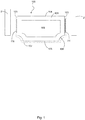
- Fig. 1 illustrates a cross section of a spacer 100 according to the invention and a set of glass panes 2 to be arranged adjacent to the side surfaces 103 of said spacer 100.
- the glass panes 2 are included for illustrative purposes only and should not be considered part of the invention.
- the spacer 100 comprises a body 106 comprising two side surfaces 103, an inside top surface 104, and a lower outer surface 105, and preferably a metal foil 107 covering at least said lower outer surface 105.
- the body 106 may be made of a polymer material.
- a transition region 199 may connect the side surfaces 103 to the lower outer surface 105.
- An inner compartment 108 may be bounded by said surfaces 103, 104, 105, 199.
- the inner compartment 108 may comprise a moisture-absorbent material.
- top and lower in the inside top surface 104 and the lower outer surface 105 only relates to the drawings. Of course, the spacer can be turned around so that the inside top surface 104 is actually closer to the ground than the lower outer surface 105.
- the top surface is the surface pointing towards the inner space between the panes once assembled, and the lower outer surface is the surface opposite the top surface.
- the metal foil 107 is to reduce diffusion of moisture and gas into and out of the space formed between the panes 2 once assembled using a spacer 100. To reduce heat transfer from one glass pane 2 to the other pane 2, the metal foil 107 is made as thin as possible - so thin that the metal foil hardly contributes to the constructional stability of the spacer.
- the stability of the spacer relies on the stability of the polymer body 106 - an inherently flexible material.
- the lower outer surface 104 of the body may even be omitted and solely be covered by the metal foil 107 which further reduces the constructional stability of the spacer.
- the spacer 100 comprises a stiffening material 111 arranged on each side surface 103.
- the stiffening material 111 is sandwiched/arranged between the metal foil 107 and the side surface 103 and covers a majority of each side surface 103.
- the stiffening material 111 may be arranged differently, see Figs. 8-15 .
- the stiffening material 111 is made of a rigid metal, e.g. iron, which is a low-cost option, aluminium, or similar metals. The stiffening material 111 ensures that the spacer 100 is less prone to buckling during handling.
- the stiffening material 111 serves to stiffen the spacer 100, such that a certain rigidity is maintained while handling.
- the stiffening material 111 is included in the spacer 100 for easing handling in the manufacturing process or during transport and not necessarily for giving the spacer 100 certain properties once assembled between a set of panes 2.
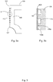
- Fig. 2 illustrates a cross section of a spacer 100 according to the invention and similar to the spacer of Fig. 1 , but where the arrangement of the metal foil 107 and stiffening material 111 has been amended slightly.
- the stiffening material 111 comprises a bend 111', such that said stiffening material 111, being primarily disposed on the side surface 103, comprises a part being embedded in the body 106 of the spacer 100.
- the metal foil 107 may likewise comprise a series of bends 107' which surround the bend 111' of the stiffening material 111.
- the metal foil 107 is likewise partly embedded in the body 106 of the spacer 100. Due to the way the metal foil 107 surrounds the stiffening material 111 within the body 106, said stiffening material 111 additionally serves to bond/fixate the metal foil 107 to the spacer 100 more strongly.
- Fig. 3 illustrates a zoom-in on a side surface 103 of a spacer according to the invention.
- the stiffening material may comprise a metal strip, it may likewise comprise a strip mesh 112 likewise made of a metal.
- the reference number "111" points to the stiffening material
- the reference number "112” points to a specific embodiment of the stiffening material, wherein said stiffening material is a strip mesh.
- the stiffening material 111 may be substituted by the stiffening material 112 (strip mesh) in all embodiments, and vice versa.
- FIG. 3a illustrates the situation where the stiffening material 112 is a strip mesh sandwiched between the side surface 103 and a metal foil 107.
- the metal foil 107 extends into the body 106 in an end portion in order to fasten said foil to the spacer in a better way.
- the metal foil may be arranged in other ways as discussed above.
- Fig. 3b illustrates a zoom-in on the region A of Fig. 3a .
- the stiffening material 112 being a strip mesh results in an alternating series of metal foil-body interfaces 109a and metal foil-stiffening material interfaces 109b. Such interfaces ensure that the metal 107 is adhered to the body 106 of the spacer in a better way and further that the stiffening material 112 is embedded in the body 106. Thereby, the stiffening material 112 is attached to the spacer more strongly.
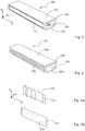
- Fig. 4 illustrates a perspective view of a spacer 100 according to the invention.
- a stiffening material 111 is arranged on one or both side surfaces 103.
- a metal foil has not been drawn to maintain simplicity.
- a metal foil covers all, or parts, of the stiffening material 111.
- the stiffening material 111 is drawn as a two-dimensional strip extending along the length of the spacer 100.
- the strip further includes a width, said width corresponding more or less to the height of the side surface 103.
- a coordinate system has been included, where the length of the spacer extends along the x-axis.
- the length of the spacer is the direction in which cross sections of the spacer 100 reveal an inner compartment 108 and are also indistinguishable.
- Fig. 5 illustrates a perspective view of a spacer 100 according to the invention.
- a stiffening material 112 embodied as a strip mesh
- a metal foil has not been drawn to maintain simplicity.
- the stiffening material 112 embodied as a strip mesh results in certain advantages as discussed in relation to Fig. 3 above.
- Fig. 6 illustrates two possible three-dimensional embodiments of the stiffening material 113, 114.
- Previously the case of a plane two-dimensional stiffening material 111 and a stiffening material embodied as a strip mesh 112 has been discussed.
- the embodiments as shown in Figs. 6a-6b illustrate a further development of such stiffening materials. More specifically, Fig. 6a illustrates a stiffening material 113 having a zigzagged shape 113' in the x-direction as supported by the coordinate system included in the illustration.
- Fig. 6b illustrates a similar situation, but where the stiffening material 114 has a zigzagged shape 114' in the z-direction again supported by the coordinate system.
- the stiffening material 113 and 114 fluctuates in the y-direction, which is preferably normal to the side surface of a spacer once mounted, as previously illustrated.
- the stiffening material, 113 and/or 114 may both be based on a solid strip or on a strip mesh.
- the purpose of having a three-dimensionally shaped stiffening material is the fact that such shaping enhances the rigidity of the spacer, since the introduced bends reduce the tendency to buckling of the stiffening material in itself which is then transferred to a further reduced tendency to buckling of the spacer.
- Other shapes are foreseen within the scope of the invention, e.g. where the stiffening material is box-shaped or staircase-shaped.
- Fig. 7 shows a cross section of a spacer 1 according to prior art positioned between two panes 2, such as glass panes.
- the spacer is connected to the glass panes e.g. by gluing.
- the spacer 1 has two side surfaces 3, an inside top surface 4, and a lower outer surface 5.
- the spacer comprises a body 6 making up the side surfaces 3 and the inside top surface 4, and a metal foil 7 covering the lower outer surface 5 and the side surfaces 3.
- the spacer resembles the spacer of Fig. 1 .
- the expression “top” and “lower” in the inside top surface 4 and the lower outer surface 5 only relates to the drawings.
- the spacer can be turned around so that the inside top surface 4 is actually closer to the ground than the lower outer surface 5.
- the top surface is the surface pointing towards the inner spacing between the panes, and the lower outer surface is the surface opposite the top surface.
- the spacers in Figs. 8-15 are only represented by rectangles, the spacers preferably have the features of Fig. 1 or Fig. 7 , or the spacers may have any other known construction.
- the spacers are shown with stiffening material.
- a gap is shown between the stiffening material and the spacers.
- the stiffening material is connected to the spacer, e.g. by gluing or welding.
- Fig. 8 shows the spacer 1 with stiffening material 21 on the side surfaces 3 on the outside of the spacer.
- the stiffening material 21 could over approximately 50 percent of the side surfaces 3.
- the general idea is that the stiffening material should contribute to the stiffness of the elongated spacer and therefore, the stiffening material should cover more than 15 % of the side surface to contribute to the stiffness of the elongated spacer. Further, by adding a stiffening material to the side surfaces of the spacer it is possible to modify the material properties of the side surfaces adding materials being optimised for connection to the material of the panes.
- Fig. 9 illustrates an embodiment where the stiffening material 31 is arranged on the inside of the spacer 1, i.e. on a surface within the inner compartment shown in Fig. 1 .
- the attachment properties of the side surface (when attached to the panes) of the spacer are not influenced by adding the stiffening material 31.
- stiffening material 41 is arranged on the outside of the spacer 1 and covering the entire side surfaces 3. This will result in a very stiff spacer 1 with a large contact surface 42 to be connected to the panes.
- stiffening material 51 is arranged on the outside of the spacer 1 thus covering the side surfaces 3 and extending around the corner 52 to the inside top surface 4.
- the stiffening material 51 has an angle or edge 52 that makes the stiffening material 51 and the spacer 1 stiff in both directions along the short sides of the spacer perpendicular to the longitudinal axis of the spacer 1.
- the longitudinal axis is along the length of the spacer 1.
- the stiffening material 51 is arranged on the outside of the spacer 1 thus covering the side surfaces 3 as well as the lower outer surface 5.
- the advantages are the same as for the embodiment shown in Fig. 11a .
- one stiffening material 51 is arranged on the outside of the spacer 1 thus covering one side surface 3 as well as the inside top surface 4, and a second stiffening material 51 is arranged on the outside of the spacer 1 thus covering one side surface 3 as well as the lower outer surface 5.
- the advantages are the same as for the embodiment shown in Fig. 11 a.
- stiffening material 61 is arranged on the outside of the spacer 1 thus covering the side surfaces 3 as well as at least parts of the inside top surface 4 and the lower outer surface 5.
- the stiffening material 61 has at least two edges 62 making said stiffening material 61 and the spacer 1 very stiff in both directions along the short sides of the spacer perpendicular to the longitudinal axis of the spacer 1.
- stiffening material 71 is arranged on the inside of the spacer 1. Edges 72 of stiffening material 71 are provided where said stiffening material 71 contacts the inside of the inside top surface 4. This embodiment has the same advantages as the embodiment shown in Figs. 9 and 11a .
- stiffening material 81 is arranged on the inside of the spacer 1. Edges 82 of stiffening material 81 are provided where said stiffening material 81 contacts the inside of the inside top surface 4 and the inside of the lower outer surface 5.
- This embodiment has the same advantages as the embodiments shown in Figs. 9 and 12 .
- stiffening material 91 is arranged around the corners 92 of the spacer 1. Since the stiffening material 91 covers all the corners, the spacer 1 is very stiff.
Landscapes
- Engineering & Computer Science (AREA)
- Civil Engineering (AREA)
- Structural Engineering (AREA)
- Securing Of Glass Panes Or The Like (AREA)
- Joining Of Glass To Other Materials (AREA)
Priority Applications (4)
| Application Number | Priority Date | Filing Date | Title |
|---|---|---|---|
| EP18167693.3A EP3556984A1 (de) | 2018-04-17 | 2018-04-17 | Abstandshalter mit doppelseitigen oberflächen |
| PCT/EP2019/059551 WO2019201809A1 (en) | 2018-04-17 | 2019-04-12 | A spacer with double side surfaces |
| PL19717888.2T PL3781774T3 (pl) | 2018-04-17 | 2019-04-12 | Element dystansowy z dwiema bocznymi powierzchniami |
| EP19717888.2A EP3781774B1 (de) | 2018-04-17 | 2019-04-12 | Abstandshalter mit doppelseitigen oberflächen |
Applications Claiming Priority (1)
| Application Number | Priority Date | Filing Date | Title |
|---|---|---|---|
| EP18167693.3A EP3556984A1 (de) | 2018-04-17 | 2018-04-17 | Abstandshalter mit doppelseitigen oberflächen |
Publications (1)
| Publication Number | Publication Date |
|---|---|
| EP3556984A1 true EP3556984A1 (de) | 2019-10-23 |
Family
ID=62017201
Family Applications (2)
| Application Number | Title | Priority Date | Filing Date |
|---|---|---|---|
| EP18167693.3A Withdrawn EP3556984A1 (de) | 2018-04-17 | 2018-04-17 | Abstandshalter mit doppelseitigen oberflächen |
| EP19717888.2A Active EP3781774B1 (de) | 2018-04-17 | 2019-04-12 | Abstandshalter mit doppelseitigen oberflächen |
Family Applications After (1)
| Application Number | Title | Priority Date | Filing Date |
|---|---|---|---|
| EP19717888.2A Active EP3781774B1 (de) | 2018-04-17 | 2019-04-12 | Abstandshalter mit doppelseitigen oberflächen |
Country Status (3)
| Country | Link |
|---|---|
| EP (2) | EP3556984A1 (de) |
| PL (1) | PL3781774T3 (de) |
| WO (1) | WO2019201809A1 (de) |
Families Citing this family (1)
| Publication number | Priority date | Publication date | Assignee | Title |
|---|---|---|---|---|
| EP4477832A1 (de) | 2023-06-14 | 2024-12-18 | Rolltech A/S | Torsionsfestes abstandhalterprofil |
Citations (14)
| Publication number | Priority date | Publication date | Assignee | Title |
|---|---|---|---|---|
| DE9214799U1 (de) | 1992-10-31 | 1992-12-24 | Kaufmann GmbH & Co. KG, 7963 Altshausen | Isolierglasscheibe |
| US5630306A (en) | 1996-01-22 | 1997-05-20 | Bay Mills Limited | Insulating spacer for creating a thermally insulating bridge |
| EP0852280A1 (de) | 1996-12-20 | 1998-07-08 | Saint-Gobain Vitrage Suisse AG | Abstandhalter für Mehrscheiben-Isolierverglasung |
| WO1999015753A1 (de) | 1997-09-25 | 1999-04-01 | Technoform Caprano + Brunnhofer Ohg | Abstandhalterprofil für isolierscheibeneinheit |
| WO1999041481A1 (de) | 1998-02-11 | 1999-08-19 | Technoform Caprano + Brunnhofer Ohg | Abstandhalterprofil für isolierscheibeneinheit |
| WO1999042693A1 (de) | 1998-02-21 | 1999-08-26 | Wilfried Ensinger | Abstandhalter |
| EP0947659A2 (de) | 1998-03-30 | 1999-10-06 | Lenhardt Maschinenbau GmbH | Abstandhalterrahmen aus glasfaserverstärktem Kunststoff für Isolierglasscheiben und Verfahren zum Bilden von Ecken in einem solchen Abstandhalter |
| EP1022424A2 (de) | 1999-01-20 | 2000-07-26 | Weidemann Unternehmensgruppe Glas | Abstandsleiste für Isolierglas |
| DE19961902A1 (de) * | 1999-12-20 | 2001-07-05 | Wilfried Ensinger | Kunststoff-Abstandshalterrahmen und Verfahren zu ihrer Herstellung |
| EP1233136A1 (de) | 2001-02-17 | 2002-08-21 | Wilfried Ensinger | Kunststoff-Abstandshalterrahmen und Verfahren zu seiner Herstellung |
| WO2003074830A1 (de) | 2002-03-06 | 2003-09-12 | Ensinger Kunststofftechnologie Gbr | Abstandhalter |
| US20050100691A1 (en) * | 2003-11-07 | 2005-05-12 | Ewin Bunnhofer | Spacer profiles for double glazings |
| DE202015105146U1 (de) * | 2015-09-30 | 2016-01-18 | Ensinger Gmbh | Polygonale Abstandhalterrahmen sowie Abstandhalterprofile zur Herstellung solcher Rahmen |
| EP3241972A1 (de) * | 2016-05-04 | 2017-11-08 | Technoform Glass Insulation Holding GmbH | Abstandshalter für isolierverglasungseinheit |
-
2018
- 2018-04-17 EP EP18167693.3A patent/EP3556984A1/de not_active Withdrawn
-
2019
- 2019-04-12 EP EP19717888.2A patent/EP3781774B1/de active Active
- 2019-04-12 WO PCT/EP2019/059551 patent/WO2019201809A1/en not_active Ceased
- 2019-04-12 PL PL19717888.2T patent/PL3781774T3/pl unknown
Patent Citations (15)
| Publication number | Priority date | Publication date | Assignee | Title |
|---|---|---|---|---|
| DE9214799U1 (de) | 1992-10-31 | 1992-12-24 | Kaufmann GmbH & Co. KG, 7963 Altshausen | Isolierglasscheibe |
| US5630306A (en) | 1996-01-22 | 1997-05-20 | Bay Mills Limited | Insulating spacer for creating a thermally insulating bridge |
| EP0852280B2 (de) | 1996-12-20 | 2009-06-17 | Saint-Gobain Glass France | Abstandhalter für Mehrscheiben-Isolierverglasung |
| EP0852280A1 (de) | 1996-12-20 | 1998-07-08 | Saint-Gobain Vitrage Suisse AG | Abstandhalter für Mehrscheiben-Isolierverglasung |
| WO1999015753A1 (de) | 1997-09-25 | 1999-04-01 | Technoform Caprano + Brunnhofer Ohg | Abstandhalterprofil für isolierscheibeneinheit |
| WO1999041481A1 (de) | 1998-02-11 | 1999-08-19 | Technoform Caprano + Brunnhofer Ohg | Abstandhalterprofil für isolierscheibeneinheit |
| WO1999042693A1 (de) | 1998-02-21 | 1999-08-26 | Wilfried Ensinger | Abstandhalter |
| EP0947659A2 (de) | 1998-03-30 | 1999-10-06 | Lenhardt Maschinenbau GmbH | Abstandhalterrahmen aus glasfaserverstärktem Kunststoff für Isolierglasscheiben und Verfahren zum Bilden von Ecken in einem solchen Abstandhalter |
| EP1022424A2 (de) | 1999-01-20 | 2000-07-26 | Weidemann Unternehmensgruppe Glas | Abstandsleiste für Isolierglas |
| DE19961902A1 (de) * | 1999-12-20 | 2001-07-05 | Wilfried Ensinger | Kunststoff-Abstandshalterrahmen und Verfahren zu ihrer Herstellung |
| EP1233136A1 (de) | 2001-02-17 | 2002-08-21 | Wilfried Ensinger | Kunststoff-Abstandshalterrahmen und Verfahren zu seiner Herstellung |
| WO2003074830A1 (de) | 2002-03-06 | 2003-09-12 | Ensinger Kunststofftechnologie Gbr | Abstandhalter |
| US20050100691A1 (en) * | 2003-11-07 | 2005-05-12 | Ewin Bunnhofer | Spacer profiles for double glazings |
| DE202015105146U1 (de) * | 2015-09-30 | 2016-01-18 | Ensinger Gmbh | Polygonale Abstandhalterrahmen sowie Abstandhalterprofile zur Herstellung solcher Rahmen |
| EP3241972A1 (de) * | 2016-05-04 | 2017-11-08 | Technoform Glass Insulation Holding GmbH | Abstandshalter für isolierverglasungseinheit |
Also Published As
| Publication number | Publication date |
|---|---|
| WO2019201809A1 (en) | 2019-10-24 |
| EP3781774B1 (de) | 2022-11-30 |
| EP3781774A1 (de) | 2021-02-24 |
| PL3781774T3 (pl) | 2023-01-16 |
Similar Documents
| Publication | Publication Date | Title |
|---|---|---|
| EP1797271B1 (de) | Abstandhalterprofil für einen abstandhalterrahmen für eine isolierfenstereinheit und isolierfenstereinheit | |
| EP2668361B1 (de) | Abstandshalterprofil und isolierglaseinheit mit solchem abstandshalter | |
| EP1529920B1 (de) | Abstandshalterprofil für Isolierscheibeneinheit und Isolierscheibeneinheit | |
| CA2385574C (en) | Sealant system for an insulating glass unit | |
| US10633914B2 (en) | Spacer for insulating glass panes | |
| KR20100126360A (ko) | 창문 또는 도어 프레임용 프로파일의 보강 시스템으로서 섬유 강화 플라스틱재의 용도 | |
| JP7052073B2 (ja) | 補強要素を有するスペーサー | |
| EP1785302B1 (de) | Türstruktur eines Kraftfahrzeuges | |
| EP2780528B1 (de) | Abstandhalterprofil mit einer verstärkung | |
| EP3781774B1 (de) | Abstandshalter mit doppelseitigen oberflächen | |
| CN105636808B (zh) | 门框 | |
| EP2746518B1 (de) | Zweiteiliger Abstandhalter mit überlappenden Oberflächen und Verfahren zu dessen Herstellung | |
| US20120304591A1 (en) | Spacer systems for insulated glass (IG) units, and/or methods of making the same | |
| EP3748101B1 (de) | Gebäudefassadenplatte und montagestruktur dafür | |
| KR102325352B1 (ko) | 시트 금속 루프 및 유리 루프를 포함하는 적어도 2 개 유형들의 차량 세트 | |
| JP2022503703A (ja) | 金属側部を有するスペーサー | |
| EP1889995A1 (de) | Abstandhalter für Glasscheiben und ein Verfahren zur Herstellung eines solchen Abstandhalters | |
| US10000963B2 (en) | Two part spacer with overlapping surfaces | |
| JP2014196643A (ja) | 多重ガラス障子用の端面保護カバー及び多重ガラス障子 | |
| CN212796475U (zh) | 车门玻璃导轨、车门玻璃导轨总成和车辆 | |
| WO2018185281A1 (en) | A spacer profile with improved stiffness | |
| JP2014196223A (ja) | 多重ガラス障子の製造方法 | |
| WO2003074831A1 (de) | Abstandhalter | |
| JP3000019B1 (ja) | 扉 | |
| JP2000199378A (ja) | 板ガラス用弾性シ―ル材 |
Legal Events
| Date | Code | Title | Description |
|---|---|---|---|
| PUAI | Public reference made under article 153(3) epc to a published international application that has entered the european phase |
Free format text: ORIGINAL CODE: 0009012 |
|
| STAA | Information on the status of an ep patent application or granted ep patent |
Free format text: STATUS: THE APPLICATION HAS BEEN PUBLISHED |
|
| AK | Designated contracting states |
Kind code of ref document: A1 Designated state(s): AL AT BE BG CH CY CZ DE DK EE ES FI FR GB GR HR HU IE IS IT LI LT LU LV MC MK MT NL NO PL PT RO RS SE SI SK SM TR |
|
| AX | Request for extension of the european patent |
Extension state: BA ME |
|
| STAA | Information on the status of an ep patent application or granted ep patent |
Free format text: STATUS: THE APPLICATION IS DEEMED TO BE WITHDRAWN |
|
| 18D | Application deemed to be withdrawn |
Effective date: 20200603 |