US5627457A - Power supply device, liquid crystal display device, and method of supplying power - Google Patents
Power supply device, liquid crystal display device, and method of supplying power Download PDFInfo
- Publication number
- US5627457A US5627457A US08/276,470 US27647094A US5627457A US 5627457 A US5627457 A US 5627457A US 27647094 A US27647094 A US 27647094A US 5627457 A US5627457 A US 5627457A
- Authority
- US
- United States
- Prior art keywords
- voltage
- impedance conversion
- conversion means
- driven
- source
- Prior art date
- Legal status (The legal status is an assumption and is not a legal conclusion. Google has not performed a legal analysis and makes no representation as to the accuracy of the status listed.)
- Expired - Lifetime
Links
Images


Classifications
-
- G—PHYSICS
- G09—EDUCATION; CRYPTOGRAPHY; DISPLAY; ADVERTISING; SEALS
- G09G—ARRANGEMENTS OR CIRCUITS FOR CONTROL OF INDICATING DEVICES USING STATIC MEANS TO PRESENT VARIABLE INFORMATION
- G09G3/00—Control arrangements or circuits, of interest only in connection with visual indicators other than cathode-ray tubes
- G09G3/20—Control arrangements or circuits, of interest only in connection with visual indicators other than cathode-ray tubes for presentation of an assembly of a number of characters, e.g. a page, by composing the assembly by combination of individual elements arranged in a matrix no fixed position being assigned to or needed to be assigned to the individual characters or partial characters
- G09G3/34—Control arrangements or circuits, of interest only in connection with visual indicators other than cathode-ray tubes for presentation of an assembly of a number of characters, e.g. a page, by composing the assembly by combination of individual elements arranged in a matrix no fixed position being assigned to or needed to be assigned to the individual characters or partial characters by control of light from an independent source
- G09G3/36—Control arrangements or circuits, of interest only in connection with visual indicators other than cathode-ray tubes for presentation of an assembly of a number of characters, e.g. a page, by composing the assembly by combination of individual elements arranged in a matrix no fixed position being assigned to or needed to be assigned to the individual characters or partial characters by control of light from an independent source using liquid crystals
- G09G3/3611—Control of matrices with row and column drivers
- G09G3/3674—Details of drivers for scan electrodes
-
- G—PHYSICS
- G05—CONTROLLING; REGULATING
- G05F—SYSTEMS FOR REGULATING ELECTRIC OR MAGNETIC VARIABLES
- G05F3/00—Non-retroactive systems for regulating electric variables by using an uncontrolled element, or an uncontrolled combination of elements, such element or such combination having self-regulating properties
- G05F3/02—Regulating voltage or current
- G05F3/08—Regulating voltage or current wherein the variable is dc
- G05F3/10—Regulating voltage or current wherein the variable is dc using uncontrolled devices with non-linear characteristics
- G05F3/16—Regulating voltage or current wherein the variable is dc using uncontrolled devices with non-linear characteristics being semiconductor devices
- G05F3/20—Regulating voltage or current wherein the variable is dc using uncontrolled devices with non-linear characteristics being semiconductor devices using diode- transistor combinations
- G05F3/24—Regulating voltage or current wherein the variable is dc using uncontrolled devices with non-linear characteristics being semiconductor devices using diode- transistor combinations wherein the transistors are of the field-effect type only
-
- G—PHYSICS
- G09—EDUCATION; CRYPTOGRAPHY; DISPLAY; ADVERTISING; SEALS
- G09G—ARRANGEMENTS OR CIRCUITS FOR CONTROL OF INDICATING DEVICES USING STATIC MEANS TO PRESENT VARIABLE INFORMATION
- G09G3/00—Control arrangements or circuits, of interest only in connection with visual indicators other than cathode-ray tubes
- G09G3/20—Control arrangements or circuits, of interest only in connection with visual indicators other than cathode-ray tubes for presentation of an assembly of a number of characters, e.g. a page, by composing the assembly by combination of individual elements arranged in a matrix no fixed position being assigned to or needed to be assigned to the individual characters or partial characters
- G09G3/34—Control arrangements or circuits, of interest only in connection with visual indicators other than cathode-ray tubes for presentation of an assembly of a number of characters, e.g. a page, by composing the assembly by combination of individual elements arranged in a matrix no fixed position being assigned to or needed to be assigned to the individual characters or partial characters by control of light from an independent source
- G09G3/36—Control arrangements or circuits, of interest only in connection with visual indicators other than cathode-ray tubes for presentation of an assembly of a number of characters, e.g. a page, by composing the assembly by combination of individual elements arranged in a matrix no fixed position being assigned to or needed to be assigned to the individual characters or partial characters by control of light from an independent source using liquid crystals
- G09G3/3611—Control of matrices with row and column drivers
- G09G3/3696—Generation of voltages supplied to electrode drivers
-
- G—PHYSICS
- G09—EDUCATION; CRYPTOGRAPHY; DISPLAY; ADVERTISING; SEALS
- G09G—ARRANGEMENTS OR CIRCUITS FOR CONTROL OF INDICATING DEVICES USING STATIC MEANS TO PRESENT VARIABLE INFORMATION
- G09G2320/00—Control of display operating conditions
- G09G2320/04—Maintaining the quality of display appearance
- G09G2320/041—Temperature compensation
-
- G—PHYSICS
- G09—EDUCATION; CRYPTOGRAPHY; DISPLAY; ADVERTISING; SEALS
- G09G—ARRANGEMENTS OR CIRCUITS FOR CONTROL OF INDICATING DEVICES USING STATIC MEANS TO PRESENT VARIABLE INFORMATION
- G09G2320/00—Control of display operating conditions
- G09G2320/06—Adjustment of display parameters
- G09G2320/0606—Manual adjustment
-
- G—PHYSICS
- G09—EDUCATION; CRYPTOGRAPHY; DISPLAY; ADVERTISING; SEALS
- G09G—ARRANGEMENTS OR CIRCUITS FOR CONTROL OF INDICATING DEVICES USING STATIC MEANS TO PRESENT VARIABLE INFORMATION
- G09G2320/00—Control of display operating conditions
- G09G2320/06—Adjustment of display parameters
- G09G2320/066—Adjustment of display parameters for control of contrast
Definitions
- the present invention relates to a power supply device, a liquid crystal display device that includes this power supply device, and a method of supplying power.
- FIG. 33 An example of a prior art power supply device that is used in electronic devices such as a liquid crystal display device is shown in FIG. 33. It should be noted at this point that the description below takes a power supply device used in a liquid crystal display device by way of example only.
- This power supply device 320 comprises a voltage regulation portion 322 and a multi-value voltage generation portion 324.
- the voltage regulation portion 322 has the function of generating a regulated voltage Vreg by adjusting a voltage between two supply voltages VS and VDD, and comprises a control portion 314 and a voltage-divider resistor 313.
- the control portion 314 further comprises switches S1 to S4 that control the resistance of the voltage-divider resistor 313 on the basis of regulated-voltage setting signals that are input thereto.
- the voltage-divider resistor 313 comprises resistors R1 to R4, these resistors R1 to R4 are selectively bypassed by control from the control portion 314, this varies the resistance of the voltage-divider resistor 313, and thus the regulated voltage Vreg is determined. Enabling voltage regulation in this manner allows the user to adjust the contrast of the liquid crystal display.
- the multi-value voltage generation portion 324 further comprises a voltage-divider resistor 312 formed of resistors Ra to Re. It has the function of dividing the regulated voltage Vreg from the voltage regulation portion 322 to generate supply voltages V0 to V5 of different magnitudes, This generation of multi-value supply voltages V0 to V5 makes it possible to implement a method such as a 6-level drive method to drive the liquid crystal display.
- FIG. 34 Another example of a prior art power supply device is shown in FIG. 34.
- the power supply device 321 of this figure differs from that of FIG. 33 in that a multi-value voltage generation portion 326 thereof comprises operational amplifiers (OP-amps) 301 to 305 connected in a voltage-follower manner.
- Each of these OP-amps 301 to 305 is connected to one of divider terminals (taps) 330 to 338 of the voltage-divider resistor 312.
- These OP-amps 301 to 305 convert the impedances of the divided voltages generated at the corresponding divider terminals 330 to 338.
- all of the OP-amps 301 to 305 have the configuration that will be described later with reference to FIG. 10 (n-type OP-amp).
- the voltage regulation portion 322 shown in FIG. 33 and FIG. 34 turn on and off switches S1 to $4 of the control portion 314, on the basis of the regulated-voltage setting signals. This adjusts the number of steps in the voltage-divider resistor connected between the supply voltages VS and VDD, to generate the regulated voltage Vreg.
- This regulated voltage Vreg is then divided by the voltage-divider resistor 312 of the multi-value voltage generation portion 324 or 326.
- these divided voltages are output without any impedance conversion as the multi-value driving supply voltages V0 to V5.
- the impedances of these divided voltages are converted by the OP-amps 301 to 305 that are connected in a voltage-follower manner, to generate the multi-value driving supply voltages V0 to V5 that are output.
- driving supply voltages V0 to V5 are supplied to a liquid crystal drive signal generation portion (LCD driver) that is not shown in the figures.
- This drive signal generation portion generates drive signals for driving the liquid crystal panel on the basis of these driving supply voltages V0 to V5.
- Liquid crystal display devices are often used in portable electronics equipment. That is why it is considered that the demand current of such a liquid crystal display device must be made extremely low to reduce the power consumption. A further concern is not only to reduce the power consumption of the liquid crystal display device in this manner, but also increase its display quality. In order to ensure a lower power consumption for the liquid crystal display device, it is necessary to reduce the power consumption of a power supply device that supplies power to the liquid crystal display device. Further, in order to ensure a higher display quality for the liquid crystal display device, the supply voltages supplied from the power supply device must be such that they do not adversely affect the display quality of the liquid crystal display device.
- the power supply device of the liquid crystal display device enables voltage regulation.
- this voltage regulation is provided by the voltage regulation portion 322 varying the number of divisions in the resistors connected between the supply voltages.
- the resistances of the voltage-divider resistors 312 and 313 are R12 and R13.
- the resistance R13 is determined by which of the switches in the control portion 314 are on.
- the regulated voltage Vreg is determined by the ratio of these resistances R12 and R13, as expressed by the equation below. Note that in the description below, VDD is assumed to be 0 V and VS is assumed to be a negative voltage such as -9 V.
- the resistance R13 can be varied between 0 and 15R (R13tot), as described above, so that the value of Vreg can be varied as shown in FIG. 35A.
- Vreg has a maximum value Vrmax (negative) given by the following equation:
- Vreg has a minimum value Vrmin (negative) given by the following equation:
- the voltage regulation range Vrange should also be capable of being set to as wide a range as possible.
- Equation 4 if it is desired to widen the voltage regulation range Vrange of either of the above prior art examples, it is necessary to either reduce the resistance R12 of the voltage-divider resistor 312 that sets the number of divisions, or increase the total resistance R13tot of the voltage-divider resistor 313 that enables the switching of the steps.
- the former method since the resistance of the voltage-divider resistor is small, the consumption of current flowing between the supply voltage VDD and the supply voltage VS is large, the problem of providing a low power consumption cannot be solved.
- the aspect ratio of the resistors made of a material such as polysilicon becomes too large, causing the problem that the chip area increases.
- This enables voltage regulation within a range of, for example, seven levels above and eight levels below the central value, so that contrast regulation can be provided over a range that is the same on both the light side and the dark side.
- manufacturing variations occur in the semiconductor devices or liquid crystal display elements that include this power supply device, due to factors such as changes in processing conditions.
- Vc voltage regulation in the range above Vc can be performed over only four levels, and it is no longer possible to provide contrast regulation over ranges that are the same on both the light side and the dark side of the center. This makes it impossible to solve the problem concerning improving the display quality.
- One method of solving this problem that has been considered is to increase the number of divisions of the voltage-divider resistor 313 and thus broaden the range of voltage regulation, to allow for manufacturing variations, but this method causes a further problem in that it increases the area of the semiconductor chip.
- voltage regulation in the prior art power supply device is provided by switching the number of divisions of the voltage-divider resistor, it is necessary to store the value for determining this central value Vc, such as the value (0111) in FIG. 35A and (0100) in FIG. 35B, in means such as non-volatile memory, which raises the problem of making the circuit configuration complicated when it comes to building the system.
- the regulated voltage Vreg is determined by the supply voltage VS or the like, and the resistance ratio of the voltage-divider resistors 312 and 313. Therefore, there is a problem in that, if the supply voltage should change, the regulated voltage Vreg will also change, such that in a liquid crystal display device that uses a battery as a power source, any change in the voltage of the battery will lead to a change in display quality.
- a liquid crystal display device has common electrodes and segment electrodes, where the common electrodes are provided with a common signal (scanning signal) for determining whether or not lines are selected. Further, the segment electrodes are provided with a segment signal (data signal) for determining whether or not display pixels are lit.
- the voltage of each common electrode is V5 (or V0) in a selected period or V1 (or V4) in a non-selected period.
- These multi-value supply voltages V0 to V5 are generated by either of the multi-value voltage generation portions 324 and 326.
- the multi-value voltage generation portion 324 of FIG. 33 divides the supply voltage by the voltage-divider resistor 312 and the resultant values are used unchanged as V0 to V5.
- the resistances of the resistors Ra to Re that form the voltage-divider resistor 312 must be as high as possible, so that the currents flowing through the voltage-divider resistor 312 are as low as possible.
- the above problem is solved by using the OP-amps 301 to 305, which are connected in a voltage-follower manner, to convert the impedances of the divided voltages generated at the divider terminals 330 to 338.
- the output impedances of the multi-value voltage generation portion 326 are reduced by the impedance conversion provided by the OP-amps 301 to 305, so that deterioration of the liquid crystal display quality can be prevented.
- increasing the output impedances at the divider terminals 330 to 338 causes no problems, so the resistances of Ra to Re can be increased. If the resistances of Ra to Re are increased, the currents flowing through the voltage-divider resistor 312 can be reduced, and thus it becomes possible to design a device with reduced power consumption.
- Each of-these OP-amps 301 to 305 is provided with a drive portion having a resistor or constant-current source connected at one end to a high-potential power-source side and an n-channel drive transistor connected at one end to a low-potential power-source side.
- a resistor or constant-current source connected at one end to a high-potential power-source side
- an n-channel drive transistor connected at one end to a low-potential power-source side.
- the p-type OP-amp is configured such that the input portion of its differential amplifier portion has an n-channel transistor and a constant-current source is connected to the low-potential power source side thereof. Therefore, in order to operate the n-channel transistor of the input portion and an n-channel transistor of the constant-current source normally (to make the voltage between the drain and source of each transistor sufficiently large), a high potential must be input to the transistor in the input portion, and that is why a p-type OP-amp is connected to V1. Conversely, the n-type OP-amp is configured such that the input portion of its differential amplifier portion has a p-channel transistor and a constant-current source is connected to the high-potential power source side thereof.
- This invention is intended to solve the above problems, and has as its objective the provision of a power supply device, a liquid crystal display device, and a method of supplying power that can enable designs with lower power consumptions and can also enable higher display qualities.
- a power supply device in accordance with this invention comprises a voltage regulation means, and is configured to supply a supply voltage that has been regulated by the voltage regulation means to an object to be driven, wherein:
- the voltage regulation means comprises a first voltage generation means for generating a first, constant voltage from a supply voltage; an adder means for adding to the first voltage a second voltage that does not depend on the first voltage; and a control means for variably controlling the second voltage within a predetermined voltage regulation range that is defined to include the first voltage.
- a first, constant voltage is generated from a supply voltage.
- a second voltage that does not depend on the first voltage is then generated, and this second voltage is added to the first voltage.
- the second voltage is variably controlled within a predetermined voltage regulation range that is defined to include the first voltage, and thus a desired regulated voltage can be supplied to the object to be driven.
- a particular feature of the present invention is the way in which the second voltage does not depend upon the first voltage. Therefore, even if the first voltage is adjusted by means for adjusting the first voltage, this does not affect the way in which the second voltage can be regulated by the control means within the predetermined voltage regulation range.
- the first voltage can be adjusted independently of other factors such as the voltage regulation range, and thus undesirable effects such as a narrowing of the voltage regulation range due to changing of the first voltage can be efficiently prevented.
- This enables an extremely flexible form of voltage regulation that does not exist in the prior art, which leads to improvements in the display quality and other characteristics of the object to be driven that is driven on the basis of the regulated voltage.
- the first voltage generated by the first voltage generation means and the second voltage added to the first voltage by the adder means have a temperature characteristic which compensates for a temperature characteristic of the object to be driven.
- the first and second voltage have a temperature characteristic that compensates for a temperature characteristic of the object to be driven. This ensures that, if the element characteristics of the object to be driven are changed by a change in temperature, the first voltage, the second voltage, and the regulated voltage obtained by adding the first and second voltages change in such a manner as to compensate for this change in element characteristics. This makes it possible to provide a stable power supply that is not affected by temperature changes, so that a drive based on this regulated voltage can be provided, enabling extremely good display quality and other characteristics of the object to be driven.
- the second voltage added by the adder means is fixed at a predetermined value during the initial operation of the device.
- the second voltage added to the first voltage is fixed at a predetermined value during the initial operation of the device.
- This enables the regulated voltage that is output from the power supply device to be fixed at a desired value during the initial operation.
- the regulated voltage can be fixed at any value within the voltage regulation range, such as the central value, the minimum value, or the maximum value. This makes it unnecessary to include any variation-adjustment program in the firmware used for generating the regulated voltage, or provide circuitry for detecting the output voltage of the voltage regulation portion.
- the device can be made smaller, and also the chip size can be reduced when this device is incorporated in a semiconductor device.
- the first voltage generation means comprises an operational amplifier, a reference voltage source connected to a first input terminal of the operational amplifier, a first resistor connected at one end to a second input terminal of the operational amplifier and at the other end to a fixed potential, and a second resistor connected at one end to the second input terminal of the operational amplifier and at the other end to an output terminal of the operational amplifier; and the adder means comprises means for making a current from a constant-current source, which is variably controlled by the control means, flow through the second resistor.
- the first voltage is determined by a reference voltage from the reference voltage source and the resistances of the first and second resistors.
- the second voltage is generated by the flowing of a current from the constant-current source, which is variably controlled by the control means, through the second resistor, and this second voltage is added to the first voltage.
- the first voltage can be adjusted by adjusting the resistance of the first resistor.
- the second voltage can be adjusted independently of the first voltage, by adjusting the current that flows in the second resistor from the constant-current source. This also means that the voltage regulation range of the second voltage can be made independent of the first voltage.
- the voltage regulation range of the prior art there is no need to provide a large number of divisions for the switchable resistors, and thus it is possible to make the device smaller and reduce semiconductor chip sizes.
- the circuit configuration simpler than that of the prior art, it becomes possible to design for lower power consumptions. Since the first voltage is determined by a reference voltage from the reference voltage source and the second voltage is determined based on a current from the constant-current source, a stable regulated voltage and voltage regulation range can be achieved, independent of changes in the supply voltage.
- the reference voltage source and the constant-current source comprise MOS transistors, and a reference voltage from the reference voltage source and a constant current from the constant-current source are generated by using the threshold voltages of the MOB transistors.
- the threshold voltage of a MOS transistor has a negative temperature characteristic. This makes it possible to provide negative temperature characteristics for the first voltage, second voltage, regulated voltage, and voltage regulation range, without having to add any element that has a temperature characteristic, such as a thermistor.
- the present invention can provide a power supply device that is suitable for a liquid crystal display device in which the contrast and other characteristics have negative temperature characteristics.
- a power supply device of the present invention comprises a multi-value voltage generation means and is configured to supply multi-value driving supply voltages from the multi-value voltage generation means, wherein:
- the multi-value voltage generation means comprises a voltage divider means for generating divided voltages at divider terminals thereof, and a plurality (at least three) of impedance conversion means connected between the divider terminals and the objects to be driven for converting the impedances of the divided voltages generated at the divider terminals, thus generating multi-value driving supply voltages intended for capacitive objects to be driven; and
- the configuration is such that a first impedance conversion means having a drive portion that draws in a large positive charge is connected to an object to be driven when the polarity of the charge that must be transferred from the object to be driven to the impedance conversion means during the drive period is positive in total, and a second impedance conversion means having a drive portion that draws in a large negative charge is connected to an object to be driven when the polarity of the charge that must be transferred from the object to be driven to the impedance conversion means during the drive period is negative in total.
- divided voltages are generated by a voltage divider means, and these divided voltages are supplied to the objects to be driven after their impedances have been converted by an impedance conversion means.
- impedance conversion is performed by a first impedance conversion means having a drive portion that draws in a large positive charge.
- impedance conversion is performed by a second impedance conversion means having a drive portion that draws in a large negative charge.
- this aspect of the present invention can make it easy to determine what type of OP-amp should be used for the third and subsequent impedance conversion means.
- the present inventin is applied to a liquid crystal display device that uses 6-level drive method, for instance, it is possible to easily determine what type of impedance conversion means should be used for each of the four impedance conversion means.
- each of the first and second impedance conversion means is formed of a voltage-follower connected operational amplifier comprising a differential portion and a drive portion;
- the drive portion of the first impedance conversion means comprises a constant-current source or resistor connected at one end to a high-potential power-source side and at the other end to an output-terminal side, and an n-channel drive transistor connected at one end to a low-potential power-source side and at the other end to the output-terminal side;
- the drive portion of the second impedance conversion means comprises a p-channel drive transistor connected at one end to the high-potential power-source side and at the other end to the output-terminal side, and a constant-current source or resistor connected at one end to the low-potential power-source side and at the other end to the output-terminal side.
- the impedances of the divided voltages are converted by the voltage-follower connected operational amplifiers, and supply voltages of the same voltages as the divided voltages are supplied to the objects to be driven.
- the drive portion of the first impedance conversion means comprises a constant-current source or resistor connected to a high-potential side and an n-channel drive transistor connected to a low-potential side
- the drive portion of the second impedance conversion means comprises a constant-current source or resistor connected to the low-potential side and a p-channel drive transistor connected to the high-potential side.
- the first impedance conversion means is connected to an object to be driven when the polarity of the charge that must be transferred from the object to be driven to the impedance conversion means is positive in total. Therefore, this positive charge can be sufficiently absorbed by the n-channel drive transistor in the drive portion, and thus the current flowing in the constant-current source or the resistor can be made sufficiently small.
- the second impedance conversion means is connected to an object to be driven when the polarity of the charge that must be transferred from the object to be driven to the impedance conversion means is negative in total. Therefore, this negative charge can be sufficiently absorbed by the p-channel drive transistor in the drive portion, and thus the current flowing in the constant-current source or the resistor can be made sufficiently small.
- a power supply device of this invention is characterized in comprising a control means for controlling one or a plurality of multi-value driving supply voltages generated by the multi-value voltage generation means, in such a manner that the voltage or voltages reach predetermined levels within a predetermined period immediately after the power is turned on.
- a power supply device of this invention is characterized in comprising a control means for controlling the one or a plurality of multi-value driving supply voltages generated by the multi-value voltage generation means, in such a manner that the voltage or voltages reach predetermined levels within a predetermined period immediately after the power is turned on; wherein the control means comprises means for increasing the current flowing into the low-potential power-source side of the drive portion of the second impedance conversion means during the predetermined period, when the high-potential power source acts as a fixed-potential power source and the low-potential power source is turned on.
- the current flowing into the low-potential power-source side of the drive portion of the second impedance conversion means is increased during the predetermined period immediately after the power is turned on.
- a power supply device of this invention is characterized in comprising a control means for controlling one or a plurality of multi-value driving supply voltages generated by the multi-value voltage generation means, in such a manner that the voltage or voltages reach predetermined levels within a predetermined period immediately after the power is turned on; wherein the control means comprises means for increasing the current flowing from the high-potential power-source side of the drive portion of the first impedance conversion means during the predetermined period, when the low-potential power source acts as a fixed-potential power source and the high-potential power source is turned on.
- the current flowing through the high-potential power-source side of the drive portion of the first impedance conversion means is increased during the predetermined period immediately after the power is turned on.
- a voltage in a transient state from the multi-value driving power source is controlled such that it is not applied to the object to be driven during the predetermined period.
- the driving supply voltages are supplied to the objects to be driven. This can more completely prevent any adverse effects that may be caused by driving supply voltages in a transient state, enabling further improvements in the display quality and other characteristics of the objects to be driven.
- a power supply device of this invention comprises a multi-value voltage generation means and is configured to supply multi-value driving supply voltages from the multi-value voltage generation means, wherein:
- the multi-value voltage generation means comprises a voltage divider means for generating divided voltages at divider terminals thereof; a plurality of impedance conversion means connected between the divider terminals and the objects to be driven for converting the impedances of the divided voltages generated at the divider terminals, thus generating multi-value driving supply voltages intended for capacitive objects to be driven; and means for controlling the impedance conversion means;
- the impedance conversion means is formed of a voltage-follower connected operational amplifier comprising a differential portion and a drive portion; and the drive portion comprises a constant-current source or resistor connected at one end to a first power-source side and at the other end to an output-terminal side, and a drive transistor connected at one end to a second power-source side and at the other end to an output-terminal side; and
- the means for controlling the impedance conversion means controls a current to flow through the constant-current source or the resistor of the impedance conversion means only during a fixed period immediately after the rise or fall of the reference clock that is used in driving the object to be driven.
- the means for controlling the impedance conversion means controls a current to flow through the constant-current source or resistor within the impedance conversion means only during a fixed period immediately after the rise or fall of the reference clock.
- a capacitive object to be driven is to be driven, load is applied to the driving supply voltages only during a fixed period immediately after the rise or fall of the reference clock. Therefore, if current flows through the constant-current source or resistor only during this period, the object to be driven can be sufficiently driven by this constant-current source or resistor. This ensures that current can be restrained from flowing through the constant-current source or the resistor during periods other than the above period, and thus the device can be designed to have an even lower power consumption.
- a power supply device of this invention comprises a multi-value voltage generation means and is configured to supply multi-value driving supply voltages from the multi-value voltage generation means; wherein:
- the multi-value voltage generation means comprises a voltage divider means for generating divided voltages at divider terminals thereof; a plurality of impedance conversion means connected between the divider terminals and the objects to be driven for converting the impedances of the divided voltages generated at the divider terminals, thus generating multi-value driving supply voltages intended for capacitive objects to be driven; and means for controlling the impedance conversion means;
- the impedance conversion means is formed of a voltage-follower connected operational amplifier comprising a differential portion and a drive portion; and the drive portion comprises a constant-current source or resistor connected at one end to a first power-source side and at the other end to an output-terminal side, and a drive transistor connected at one end to a second power-source side and at the other end to an output-terminal side; and
- the means for controlling the impedance conversion means puts limitations on a current that flows through the constant-current source or the resistor of the impedance conversion means.
- the current flowing in the constant-current source or the resistor within the impedance conversion means is limited by the means for controlling the impedance conversion means when the frame signal (an alternation signal in frame inversion technique or line inversion technique) is at a predetermined level.
- the frame signal an alternation signal in frame inversion technique or line inversion technique
- this configuration ensures that, if the current flowing in the constant-current source or the resistor is controlled, the flow of unnecessary demand current in the constant-current source or resistor can be efficiently prevented. This enables the design of devices with even lower power consumptions, without any deterioration in the display quality and other characteristics of the object to be driven.
- the drive portion comprises a constant-current source or resistor that is controlled by the means for controlling the impedance conversion means, and another constant-current source or resistor that is not controlled by the control means.
- the output voltage of the drive portion can be held at a fixed value by the constant-current source or resistor that is not controlled by the control means.
- the current flowing in the constant-current source or the resistor is controlled by the control means in accordance with the load applied to the driving supply voltages, a drive portion having sufficient drive capability with a low power consumption can be implemented.
- a power supply device of this invention comprises a voltage regulation means and a multi-value voltage generation means, and is configured to supply multi-value driving supply voltages generated by the multi-value voltage generation means from a regulated voltage generated by the voltage regulation means, wherein:
- the voltage regulation means comprises a first voltage generation means for generating a first, constant voltage from a supply voltage; an adder means for adding to the first voltage a second voltage that does not depend on the first voltage; and a control means for variably controlling the second voltage within a predetermined voltage regulation range that is defined to include the first voltage;
- the multi-value voltage generation means comprises a voltage divider means for dividing a regulated voltage generated at the voltage regulation means, thus generating divided voltages by divider terminals thereof; and a plurality (at least three) of impedance conversion means connected between the divider terminals and the objects to be driven for converting the impedances of the divided voltages generated at the divider terminals, thus generating multi-value driving supply voltages intended for capacitive objects to be driven; and
- the configuration is such that a first impedance conversion means having a drive portion that draws in a large positive charge is connected to an object to be driven when the polarity of the charge that must be transferred from the object to be driven to the impedance conversion means during the drive period is positive in total, and a second impedance conversion means having a drive portion that draws in a large negative charge is connected to an object to be driven when the polarity of the charge that must be transferred from the object to be driven to the impedance conversion means during the drive period is negative in total.
- the multi-value voltage generation means can be used to generate multi-value driving supply voltages whose impedances have been converted, based on a supply voltage regulated by the voltage regulation means. This ensures that the multi-value driving supply voltages generated by the multi-value voltage generation means can be regulated. Further, multi-value supply voltages that are appropriate for the loads applied to the driving supply voltages can be supplied to the capacitive objects to be driven. If devices such as operational amplifiers are used for voltage regulation in the voltage regulation means, these operational amplifiers can also be used as impedance conversion means in the multi-value voltage generation means. This enables the design of even smaller devices.
- a liquid crystal display device of this invention comprises a voltage regulation means, wherein supply voltages for driving liquid crystal elements are regulated by the voltage regulation means, thus regulating contrast for a liquid crystal display, and wherein:
- the voltage regulation means comprises a first voltage generation means for generating a first, constant voltage from a supply voltage; an adder means for adding to the first voltage a second voltage that does not depend on the first voltage; and a control means for variably controlling the second voltage within a predetermined voltage regulation range that is defined to include the first voltage.
- the contrast of the liquid crystal display is regulated by having the voltage regulation means regulate the supply voltages for driving liquid crystal elements.
- regulation of a voltage that acts as reference for the contrast regulation is enabled by regulating the first voltage.
- the user of the liquid crystal display device can then obtain any desired contrast by regulating the second voltage.
- regulating the first voltage to change the central or other value will have no effect on the second voltage. Therefore, the central or other value, the second voltage, and the voltage regulation range can be set individually and independently, to enable contrast regulation that is superior to that of the prior art. This enables the provision of the optimal contrast regulation method for the liquid crystal display devices that are often used in portable electronics equipment where small size and light weight are necessary.
- a liquid crystal display device of this invention comprises a multi-value voltage generation means and is configured to use a 6-level drive method to drive a liquid crystal element that is an object to be driven, on the basis of multi-value driving supply voltages generated by the multi-value voltage generation means;
- the multi-value voltage generation means comprises a voltage divider means for generating divided voltages at divider terminals thereof, and a plurality of impedance conversion means connected between the divider terminals and the objects to be driven for converting the impedances of the divided voltages generated at the divider terminals, thus generating multi-value driving supply voltages intended for capacitive objects to be driven; and
- each of the second and fourth levels of driving supply voltage is generated by a first impedance conversion means having a drive portion that draws in a large positive charge from the object to be driven to the impedance conversion means, and each of the first and third levels of driving supply voltage is generated by a second impedance conversion means having a drive portion that draws in a large negative charge from the object to be driven to the impedance conversion means.
- the second and fourth levels of driving supply voltage where the charge that must be transferred to the impedance conversion means is positive in total, are generated by a first impedance conversion means having a drive portion that draws in a large positive charge.
- the first and third levels of driving supply voltage, 30 where the charge is negative in total are generated by a second impedance conversion means having a drive portion that draws in a large negative charge.
- FIG. 1 is a block diagram of a power supply device according to a first embodiment of this invention
- FIG. 2A and FIG. 2B are diagrams illustrating the voltage regulation method of the first embodiment
- FIG. 3 is a circuit diagram of a voltage regulation portion according to a second embodiment of this invention.
- FIG. 4 is a circuit diagram of the voltage regulation portion of FIG. 3, when the reference voltage source, constant-current source, and control portion are configured of MOS transistors;
- FIG. 5 is a circuit diagram of an example of a liquid crystal display device that uses the power supply device of this invention.
- FIG. 6 is a graph of the temperature characteristic that appears in the driving supply voltage V5 in the second embodiment
- FIG. 7 is a circuit diagram of a multi-value voltage generation portion according to a third embodiment of this invention.
- FIG. 8 is a transistor-level circuit diagram of a p-type OP-amp
- FIG. 9 is a graph of the current characteristics of an n-channel load transistor and a p-channel drive transistor
- FIG. 10 is a transistor-level circuit diagram of an n-type OP-amp
- FIG. 11A is a table listing the relationships between the voltages of common and segment electrodes and the voltages V0 to V5, and FIG. 11B illustrates an example of the arrangement of common and segment electrodes;
- FIG. 12A and FIG. 12B are simple sketches showing how much charge must be moved at the driving supply voltages when the voltages of common and segment electrodes are changed;
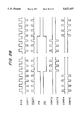
- FIG. 13 is a timing chart of the FR signal and DCK signal
- FIG. 14 are diagrams of common and segment waveforms obtained when the voltage of the segment electrode changes from V3 to V2 at the FR switchover point A;
- FIG. 15 shows the process of calculating the load applied to V2 in FIG. 14, and the calculation results obtained thereby;
- FIG. 16 are diagrams of common and segment waveforms obtained when the voltage of the segment electrode changes from V5 to V2 at the FR switchover point A;
- FIG. 17 shows the process of calculating the load applied to V2 in FIG. 16, and the calculation results obtained thereby;
- FIG. 18 are diagrams of common and segment waveforms obtained when the voltage of the segment electrode changes from V0 to V2 during the period B;
- FIG. 19 shows the process of calculating the load applied to V2 in FIG. 18, and the calculation results obtained thereby;
- FIG. 20 are diagrams of common and segment waveforms obtained when the voltage of the segment electrode remains unchanged at V2 during the period B;
- FIG. 21 shows the process of calculating the load applied to V2 in FIG. 20, and the calculation results obtained thereby;
- FIG. 22 shows the process of calculating the load applied to V1 when the voltage of the segment electrode changes from V5 to V2, or from V5 to V0, at the FR switchover point A, and the calculation results obtained thereby;
- FIG. 23 shows the process of calculating the load applied to V1 when the voltage of the segment electrode changes from V3 to V2, or from V3 to V0, at the FR switchover point A, and the calculation results obtained thereby;
- FIG. 24 shows the process of calculating the load applied to V1 when the voltage of the segment electrode changes from V0 to V2, or from V0 to V0, during the period B, and the calculation results obtained thereby;
- FIG. 25 shows the process of calculating the load applied to V1 when the voltage of the segment electrode changes from V2 to V2, or from V2 to V0, during the period B, and the calculation results obtained thereby.
- FIG. 26 lists all the results of calculating the load on V1 to V4;
- FIG. 27 is a circuit diagram of an n-type OP-amp that possess a current control function
- FIG. 28 is a timing chart of DCK, control signals, and the FR signal
- FIG. 29A shows the configuration of a multi-value voltage generation portion when the power source on the high-potential side is a fixed power source
- FIG. 29B shows the configuration of a multi-value voltage generation portion when the power source on the low-potential side is a fixed power source
- FIG. 30A and FIG. 30B illustrate the voltage changes at V1 and V4 when the power is turned on, respectively;
- FIG. 31 is a characteristic graph that illustrates the voltage changes of V1, V2, V3, V4 and V5 when the power is turned on;
- FIG. 32 is a schematic view of the power-on sequence in a fifth embodiment of this invention.
- FIG. 33 shows one example of a prior art power supply device used in a device such as a liquid crystal display device
- FIG. 34 shows another example of a prior art power supply device used in a device such as a liquid crystal display device.
- FIG. 35A and FIG. 35B are diagrams illustrating the voltage regulation method of the prior art examples of FIG. 33 and FIG. 34.
- a power supply device 100 of this first embodiment comprises a voltage regulation portion 102 and a multi-value voltage generation portion 110, as shown in FIG. 1, and it generates from a supply voltage multi-value supply voltages V0 to V5 for liquid crystal.
- the voltage regulation portion 102 comprises a first voltage generation portion 104, an adder portion 106, a second voltage generation portion 107, and a control portion 108, and it generates a regulated voltage Vreg.
- the second voltage generation portion 107 generates a second voltage Vy independently of the generation of the above first voltage. In this case, the second voltage Vy is variably controlled by the control portion 108 within a predetermined voltage regulation range that is defined to include the first voltage Vx. This variably controlled second voltage Vy is added in the adder portion 106 to the above first voltage Vx, and thus the regulated voltage Vreg is generated.
- a positive or negative value of the second voltage Vy is added to the first voltage Vx to generate the regulated voltage Vreg.
- Whatever value of second voltage Vy is added is determined by regulated-voltage setting signals that are input to the control portion 108.
- a variable second voltage Vy that does not depend on the value of the first voltage Vx is added to Vx to generate the regulated voltage Vreg. Therefore, if, as shown for example in FIG. 2B, the central value for contrast regulation is changed by variations occurring during the manufacture of the semiconductor device or liquid crystal element, the above described problem with the prior art technology will not occur.
- the variably controlled second voltage Vy is added to the first voltage Vx, the desired regulated voltage Vreg can be obtained.
- This arrangement differs from the prior art example shown in FIG. 35A and FIG. 35B in that contrast regulation can be performed within a range of substantially the same size on both the upper side and the lower side.
- Vx the first voltage Vx equals the central value; it could be made equal to either Vrmax or Vrmin in FIG. 2A and FIG. 2B. If Vx is made equal to Vrmax, the second voltage Vy added for voltage regulation would have a positive value; if Vx is made equal to Vrmin, it would have a negative value.
- the multi-value voltage generation portion 110 comprises a voltage divider portion 112 and first and second impedance conversion portions 114, 116, 118 and 120.
- the voltage divider portion 112 performs dividing between the regulated voltage Vreg and the supply voltage VDD, and divided voltages are output from divider terminals 122, 124, 126, 128, 130 and 132.
- the divider terminals 126 and 130 are connected to first impedance conversion portions 116 and 120, and supply voltages V2 and V4 which have been impedance-converted are supplied therefrom to a capacitive liquid crystal element.
- divider terminals 124 and 128 are connected to second impedance conversion portions 114 and 118, and supply voltages V1 and V3 that have been impedance-converted are supplied therefrom to the capacitive liquid crystal element.
- first impedance conversion portions 116 and 120 each having a drive portion that draws in a large positive charge
- second impedance conversion portions 114 and 118 each having a drive portion that draws in a large negative charge
- This second embodiment illustrates a specific configuration of a voltage regulation portion 102.
- the voltage regulation portion of the second embodiment shown in FIG. 3 comprises an OP-amp 6, a reference voltage source 7, a constant-current source 8 having a plurality of current sources, and a control portion 9 having a plurality of switches.
- a positive input terminal (first input terminal) of the OP-amp 6 is connected to the reference voltage source 7 and a negative input terminal (second input terminal) thereof is connected to one end of each of resistors 10 and 11 and to an output terminals of the control portion 9.
- the other end of the resistor 10 is connected to the output terminal of the OP-amp 6, and the other end of the resistor 11 is connected to a fixed potential VDD.
- the control portion 9 is positioned between the constant-current source 8 and the negative input terminal of the OP-amp 6.
- the magnitude of the current flowing from the constant-current source 8 to the resistor 10 is controlled on the basis of the regulated-voltage setting signals, and voltage regulation is performed by changing this current magnitude.
- the regulated voltage Vreg (connected to V5) that is an output of the voltage regulation portion is the sum of the first voltage Vx and the second voltage Vy, as given by the following equation:
- the first voltage Vx can be expressed by the following generalized equation for the output voltage at the OP-amp:
- the second voltage Vy is determined by a current I10 flowing from the constant-current source 8 via the control portion 9 to the resistor 10.
- the current I10 can be varied by selectively turning on the switches in the control portion 9 by the regulated-voltage setting signals. Therefore, the second voltage Vy is given by the following equation:
- the voltage regulation range Vrange is given by the following equation:
- Vy is determined by R10 and thus the voltage regulation range Vrange is also determined thereby.
- Vx is determined by R11, and thus the voltage that acts as reference for voltage regulation is determined thereby.
- This voltage that acts as reference for voltage regulation could be, as described above, the central value of the voltage regulation range, or it could be the maximum or minimum value thereof.
- each of the values of Vx, Vy, and Vrange can be set independently.
- FIG. 4 An example of the circuitry when the reference voltage source 7, constant-current source 8, and control portion 9 of FIG. 3 are configured of MOS transistors is shown in FIG. 4.
- the reference voltage source 7 comprises a p-channel transistor 15 and an n-channel transistor 20.
- the magnitude of Vref generated by the reference voltage source 7 can be made virtually the same as the threshold voltage of the p-channel transistor 15 by reducing the current capability of the n-channel transistor 20 and reducing the current flowing between the power sources.
- the constant-current source 8 comprises p-channel transistors 16 to 19.
- the constant-current source 8 provides a constant current by making use of the constant-current characteristic when saturated of the p-channel transistors 16 to 19 whose gate electrodes are connected to the reference voltage Vref.
- the control portion 9 comprises p-channel transistors 21 to 24 that are connected to the drain regions of the p-channel transistors 16 to 19 respectively, and the passing and cutting off of the current is switched by the regulated-voltage setting signals connected to the gate electrodes of the p-channel transistors 21 to 24.
- the weighting of the values of the currents flowing from the plurality of current sources within the constant-current source 8 is 2 n .
- regulated-voltage setting signals can be obtained as binary signals from registers written to by means such as a microprocessor, control by microprocessor is facilitated.
- the voltage that acts as reference for voltage regulation such as the central value
- the voltage that acts as reference for voltage regulation can be changed while the voltage regulation range is maintained. Therefore, if variations should occur during the manufacture of the semiconductor device or liquid crystal element, these variations can be compensated for by adjusting the resistance of the resistor 11 by the above resistance variation means. In other words, assume that the adjustment is such that Vx is made to match the central value Vc for contrast regulation, as shown for example in FIG. 2. Since the resistance of the resistor 10 is fixed, it is clear from Equation 9 that the voltage regulation range does not change, even if the resistance of the resistor 11 changes.
- each of these prior art power supply devices is configured with an excessively large voltage regulation range, to ensure that voltage regulation can be provided over a sufficiently broad range if there should be any change in the voltage that acts as reference for voltage regulation.
- the voltage-divider resistor 313 of FIG. 33 and FIG. 34 has an excessive number of divisions.
- the necessary lower limit required for the voltage regulation range can be fixed by this embodiment, since the voltage regulation range does not change even if the voltage that acts as reference for voltage regulation changes.
- the number of current sources in the constant-current source 8 for voltage regulation and the number of switches in the control portion 9 can be set to the necessary lower limits. Note further that this means that, if voltage regulation control signals can be obtained as binary signals from registers written to by means such as a microprocessor, the numbers of bits in the registers can be set to the necessary lower limit and the linking wiring can also be reduced.
- Vx can be equal to the minimum value Vrmin shown in FIG. 2A.
- Vx can be equal to the central value Vc, for example, as shown in FIG. 2A.
- FIG. 5 An example of a liquid crystal display device using the power supply device of this invention is shown in FIG. 5.
- This liquid crystal display device comprises a power supply device 100, a contrast regulation portion 140, a drive signal generation portion (LCD driver) 142, and a liquid crystal panel 144.
- LCD driver drive signal generation portion
- the regulated voltage Vreg that is an output of the voltage regulation portion is supplied to the drive signal generation portion 142 as supply voltage V5 for liquid crystal drive, and is also connected to one end of the voltage-divider resistor 12 of which the other end is connected to a fixed potential. Voltages divided by the voltage-divider resistor 12 are connected to positive input terminals of voltage-follower connected OP-amps 1 to 4, and outputs of the OP-amps 1 to 4 are input to the drive signal generation portion 142 as supply voltages V1, V2, V3, and V4. Note that in this case, the divider terminals 126 and 130 are connected to n-type OP-amps 2 and 4 and the divider terminals 124 and 128 are connected to p-type OP-amps 1 and 3 respectively. These OP-amps will be described in detail later. Note also that the OP-amp 6 in the voltage regulation portion can provide impedance conversion for V5, which can reduce the number of circuit elements.
- the drive signal generation portion 142 generates drive signals by selecting any of these driving supply voltages V0 to V5 on the basis of, for example, the 6-level drive method. These drive signals are used to drive liquid crystal elements. If the user performs an operation to regulate the contrast by the contrast regulation portion 140, the value of Vreg is regulated by regulated-voltage setting signals that are output by the contrast regulation portion 140. The voltages V1 to V5 supplied to the liquid crystal panel 144 are regulated in this manner, to provide contrast regulation for the liquid crystal display.
- the regulated voltage Vreg output from the voltage regulation portion bears no relationship to the resistance of the voltage-divider resistor 12, as shown by Equation 8. Therefore, the current flowing between the power sources can be made extremely small by increasing the resistance of the voltage-divider resistor 12. This makes it possible to design for extremely low power consumptions in the power supply device and liquid crystal display device.
- the power supply device of this embodiment can be applied to a liquid crystal display device, as described above, and, since a liquid crystal display device is light and has a low power consumption, it is often used in portable electronics equipment where small size and light weight are necessary. Therefore, equipment provided with such a liquid crystal display device ought to make the most of the inherent advantages of a liquid crystal display device (small size and light weight), where smaller and less power-hungry circuits are requested.
- the power supply device of this embodiment is effective means of answering these requests when used in a liquid crystal display device.
- the value of Vx which is the voltage that acts as reference for voltage regulation, is determined by the value of the reference voltage Vref and the resistance ratio of the resistors 10 and 11, as is clear from Equation 6.
- the voltage that acts as reference for voltage regulation is determined by resistance-division of the voltage difference between the supply voltages VDD and VS. Therefore, the prior art examples had the problem that a change in the supply voltage would cause a change in the voltage that acts as reference for voltage regulation.
- Vx is kept constant even if the supply voltage should change.
- the voltage Vy that determines the voltage regulation range is determined by the value of the current I10 flowing in the resistor 10 from the constant-current source 8 via the control portion 9 and the resistance of the resistor 10, as shown by Equation 7.
- the current I10 from the constant-current source 8 remains constant even if the supply voltage changes.
- Vy can also be kept constant with respect to changes in the supply voltage, so that the voltage regulation range Vrange also remains constant.
- FIG. 4 shows an example in which the constant-current source 8 of FIG. 2 or FIG. 3 is configured of transistors, where the gate voltage of a transistor operating in the constant-current region is obtained from the reference voltage Vref and, since the gate voltage is held fixed, the drain current is also fixed. This ensures that the current flowing from the constant-current source is constant, even if the supply voltage changes, and thus Vy and Vrange are also fixed.
- a further problem occurs if the element characteristics of the object to be driven, which is the destination of the regulated voltage, has temperature characteristics, in which case it is desirable for the regulated voltage to have a temperature characteristics to compensate for these temperature characteristics of the object to be driven.
- the display quality for example, of a liquid crystal display element is heavily dependent on the surrounding temperature, so, in order to ensure constant display quality, it is desirable to drive the liquid crystal display with voltages that have negative temperature characteristics with respect to the ambient temperature.
- the usual method of implementing such negative temperature characteristics involves connecting an element having temperature characteristics, such as a thermistor, to the voltage-divider resistor, to compensate the temperature characteristics.
- This embodiment is provided with temperature characteristics that compensate for the temperature characteristics of the object to be driven with respect to the first and second voltages Vx and Vy. References in the description below to FIG. 4 will make this clear.
- the value of the reference voltage Vref generated by the reference voltage source 7 is roughly the same as the threshold voltage of the p-channel transistor 15, as described above. Since the threshold voltage of a MOS transistor generally has a negative temperature characteristic, the first voltage Vx, which is determined by the value of this reference voltage Vref and the ratio of the resistances of the resistor 10 and the resistor 11, also has a negative temperature characteristic.
- the magnitude of the current flowing from the constant-current source 8 is also dependent on the threshold voltage of the MOS transistor, and thus also has a negative temperature characteristic, so the second voltage Vy and the voltage regulation range Vrange have negative temperature characteristics as well.
- the device in accordance with this embodiment can possess negative temperature characteristics with respect to both the regulated voltage Vreg and the voltage regulation range Vrange.
- this embodiment makes it possible to provide the regulated voltage Vreg and the voltage regulation range Vrange with temperature characteristics, without having to add any element having temperature characteristics, such as a thermistor. This enables a reduction in the number of components, and, when the power supply device is incorporated into a semiconductor device, it makes it possible to reduce the number of external components and design a device that is smaller and less expensive.
- FIG. 6 shows just one example of a temperature characteristic that can appear in the driving supply voltage V5 when this embodiment is used.
- V5 has a negative temperature characteristic. Therefore, if this V5 is used as a driving supply voltage for a liquid crystal element having a negative temperature characteristic, a liquid crystal display device with a good display quality can be obtained.
- This third embodiment illustrates a specific configuration of the multi-value voltage generation portion 110.
- the multi-value voltage generation portion in accordance with this third embodiment comprises a voltage divider portion 203 and OP-amps 1 to 4, as shown in FIG. 7.
- the OP-amps 1 to 4 are connected to each of divider terminals 224, 226, 228 and 230 of the voltage divider portion 203, and supply the voltages V1 to V4, respectively.
- OP-amps configured as shown in FIG. 8 (hereinafter called p-type OP-amps) are used as the OP-amps that supply V1 and V3
- OP-amps configured as shown in FIG. 10 hereinafter called n-type OP-amps) are used as the OP-amps that supply V2 and V4.
- the voltage divider portion 203 comprises nine transistors connected in series, with each drain region short-circuited to the corresponding gate electrode, and these transistors are used instead of resistors to divide the voltages. In this case, since these transistors are set to all have the same current supply capability, the voltages between V0 and V5 can be accurately divided by nine (1/9 bias). Of the voltages divided into nine in this manner, assume that the first voltage on the low side next to V0 is called V1 and the second voltage is called V2, and the first voltage on the high side next to V5 is called V4 and the second voltage is called V3. The voltage division could, of course, be done using a resistor as shown in the prior art examples of FIG. 33 and FIG. 34.
- this resistor in order to try to reduce the demand current, this resistor must have a large resistance, but the use of such a large resistance in an IC causes problems such as a large area is necessary and new fabrication processes must be added.
- this embodiment instead of large resistances, this embodiment uses transistors in which the drain region and gate electrode are short-circuited. This ensures that the consumption of current flowing though the voltage divider portion 203 can be restrained to the order of 0.2 ⁇ A.
- FIG. 8 A transistor-level circuit diagram of the p-type OP-amp of FIG. 7 is shown in FIG. 8.
- This p-type OP-amp comprises a differential amplification portion 206 and a drive portion 200.
- the circuitry of the differential amplification portion 206 has two input terminals, a positive input terminal 208 and a negative input terminal 209 and one output terminal 210, and the manner in which the circuitry amplifies the voltage difference between the two input terminals and outputs it from the output terminal 210 is well known, so further description thereof is omitted.
- the drive portion 200 has a p-channel drive transistor 204 and an n-channel load transistor 205. Further, a capacitor 207 for preventing oscillation is provided between the differential amplification portion 206 and drive portion 200.
- the configuration is a voltage-follower connection, in other words, the configuration is such that the negative input terminal 209 of the differential amplification portion 206 is connected to an output terminal 211 of the OP-amp.
- the p-channel drive transistor 204 and n-channel load transistor 205 in the drive portion 200 are connected in series, and this connection point is the output terminal 211 of the OP-amp. Connecting the drain region and gate electrode of the n-channel load transistor 205 together makes the transistor function as a resistor.
- the output terminal 211 of the OP-amp is connected to the negative input terminal 209 of the differential amplification portion 206, and the output terminal 210 of the differential amplification portion 206 is connected to the gate electrode of the p-channel drive transistor 204. Connecting the circuitry in this manner ensures that the voltage applied to the positive input terminal 208 appears at the output terminal 211 remaining the same level.
- the differential amplification portion 206 ensures that the positive input terminal 208 and the output terminal 211 of the OP-amp are at the same voltage by controlling the gate voltage of the p-channel drive transistor 204.
- FIG. 9 The relationships between the current characteristics of the n-channel load transistor 205 and p-channel drive transistor 204 of the p-type OP-amp are shown in FIG. 9.
- a curve 214 shows the current characteristic of the n-channel load transistor 205 and a curve 215 shows that of the p-channel drive transistor 204 when there is no load on the output terminal 211 of the OP-amp.
- a curve 216 shows the current characteristic of the p-channel drive transistor 204 when a negative load is applied to the output terminal 211 of the OP-amp and a curve 217 shows that when a positive load is applied to the output terminal 211 of the OP-amp.
- apply a negative load means connect to a low-level voltage (potential) to draw out a current (draw in a negative charge to the drive portion), and apply a positive load means connect to a high-level voltage (potential) to draw in a current (draw in a positive charge to the drive portion).
- the current characteristic of the p-channel drive transistor 204 is as shown by the curve 215 in FIG. 9, and, at a point A at which this current characteristic 215 intersects the current characteristic 214 of the n-channel load transistor 205, a current is flowing as a steady-state current.
- the voltage at the output terminal 211 of the OP-amp is always held at the same level as the voltage of the positive input terminal 208 of the differential amplification portion 206.
- the demand current of this p-type OP-amp is determined by the total of a demand current I1 of the differential amplification portion 206 and a demand current I2 flowing between the p-channel drive transistor 204 and the n-channel load transistor 205.
- the demand current I1 is restrained to be of the order of 0.7 ⁇ A.
- the steadily flowing demand current I2 bears no relationship with the current supply capability of the p-channel drive transistor 204 and is determined by the current supply capability of the n-channel load transistor 205. If the current supply capability of the n-channel load transistor 205 is small, the demand current I2 of the steadily flowing current is also small, but it cannot become extremely small.
- the reason why is because, when the voltage at the output terminal 211 of the OP-amp has risen (when a positive load has been applied), the capability of pulling that voltage down again is determined by the current supply capability of the n-channel load transistor 205. In other words, the voltage pulldown capability drops the more the demand current is restrained, and the demand current increases the more the voltage pulldown capability is increased.
- V1 and V3 are each connected to an OP-amp having a drive portion 200 that draws in a large negative charge, in other words, a p-type OP-amp.
- This ensures that sufficient negative charge can be pulled in from both V1 and V3 during the drive period, and thus phenomena such as shadows and cross-talk can be prevented from occurring and deterioration of the display characteristics of the liquid crystal can be prevented.
- a positive load is applied to a p-type OP-amp, a positive charge must be drawn in by the n-channel load transistor 205.
- FIG. 10 A transistor-level circuit diagram of the n-type OP-amp of FIG. 7 is shown in FIG. 10.
- This n-type OP-amp differs from the above p-type OP-amp in the configuration of a drive portion 201 thereof, where the drive portion 201 comprises an n-channel drive transistor 212 and a p-channel load transistor 213.
- the configuration of the negative input terminal 209 of the differential amplification portion 206 and the output terminal 211 of the OP-amp is such that they are in a voltage-follower connection.
- the n-type OP-amp is similar to the p-type OP-amp in that the voltage at the output terminal 211 of the OP-amp is pulled doom if it is higher than the voltage at the positive input terminal 208, but pulled up if it is lower, so that the voltage at the positive input terminal 208 is always kept the same.
- the n-type OP-amp differs from the p-type OP-amp in that, if the voltage at the output terminal 211 of the OP-amp has risen (when a positive load has been applied) the voltage pulldown capability thereof is determined by the current supply capability of the n-channel drive transistor 212.
- the voltage pullup capability thereof is determined by the current supply capability of the p-channel load transistor 213.
- short-circuiting the gate electrode and drain region of the p-channel load transistor 213 makes the transistor function as a resistor. Note that the application of a constant voltage to the gate electrode of the p-channel load transistor 213 would make the transistor function as a constant-current source.
- the demand current I2 that flows steadily through the drive portion 201 of the n-type OP-amp bears no relationship with the current supply capability of the n-channel drive transistor 212, and decreases as the current supply capability of the p-channel load transistor 213 decreases. In other words, the voltage pullup capability drops the more the demand current is restrained, and the demand current increases the more the voltage pullup capability is increased.
- V2 and V4 are each connected to an OP-amp having a drive portion 201 that draws in a large positive charge, in other words, an n-type OP-amp.
- This ensures that sufficient positive charge can be pulled in from both V2 and V4 during the drive period, and thus phenomena such as shadows and cross-talk can be prevented from occurring.
- a negative load is applied to an n-type OP-amp, a negative charge must be drawn in by the p-channel load transistor 213.
- V1 to V4 are the driving supply voltages, when a simple matrix LCD is driven in a line-by-line scanning, time-division (multiplexed) manner.
- the voltage of a common electrode is V5 (V0) during a period when the electrode is selected, and V1 (V4) when it is not selected.
- V5 V0
- V5 V5
- V5 V5
- V5 V5
- V5 V5
- V5 V5
- the display capacity of the LCD panel is 64 ⁇ 100 pixels.
- the LCD panel is provided with 64 common electrode lines and 100 segment electrode lines (see FIG. 11B).
- time-division (multiplexed) drive is performed with a 1/64 duty cycle.
- Q charge quantity
- C capacitance
- V voltage
- the value at each segment electrode is any one of V0, V2 (when the FR signal is high), V5, and V3 (when the FR signal is low). Therefore, if the voltages at the segment electrode are considered to be changes into V2, there will be the changes of: V0 ⁇ V2, V2 ⁇ V2, V5 ⁇ V2, and V3 ⁇ V2.
- the changes V0 ⁇ V2 and V2 ⁇ V2 can be ignored, and only the changes V3 ⁇ V2 and V5 ⁇ V2 need be considered.
- the changes V3 ⁇ V2 and V5 ⁇ V2 can be ignored, since they occur within the same period, and only the changes V0 ⁇ V2 and V2 ⁇ V2 need be considered.
- FIG. 14 shows only the relationships between COM1 to COM64 and SEG1.
- non-selected lines are those which have not been selected by common signals; in FIG. 14, these are the 62 (64-2) lines marked #1.
- a selection-ended line is a line where the line before it has been selected; in FIG. 14, this is the line marked #2.
- a selection-started line is a line that has been selected by a common signal; in FIG. 14, this is the line marked #3.
- the load calculations refer to these lines #1, #2, and #3.
- FIG. 16 The common and segment waveforms when the voltage of the segment electrode changes from V5 to V2 at the FR switchover point A are shown in FIG. 16.
- the calculations for FIG. 16 are divided into non-selected lines (#1), selection-ended line (#2), and selection-started line (#3).
- the calculation process and the results obtained in this case are shown in FIG. 17.
- the total charge that must be drawn into V2 is -16 C. In other words, a negative load is applied to V2 in this case.
- the common and segment waveforms when the voltage of the segment electrode changes from V0 to V2 during a period B is shown in FIG. 18.
- COM1 is a selection-ended line (#2)
- COM2 is a selection-started line (#3)
- COM3 to COM64 are non-selected lines (#1).
- COM1, COM2, and COM5 to COM64 are non-selected lines (#1)
- COM3 is a selection-ended line (#2)
- COM4 is a selection-started line (#3).
- the statuses at points B3 to B31 can be considered in a similar manner.
- the calculations for FIG. 18 are divided into non-selected lines (#1), selection-ended line (#2), and selection-started line (#3).
- the calculation process and the results obtained in this case are shown in FIG. 19.
- the total charge that must be drawn into V2 in this case is +128 C. In other words, a positive load is applied to V2 in this case. Note that the calculation results obtained at each of points B1 to B31 in FIG. 18 will be the same as that shown in FIG. 19.
- FIG. 20 The common and segment waveforms when the voltage of the segment electrode does not change and stays at V2 during the period B is shown in FIG. 20.
- the calculations for FIG. 20 are divided into non-selected lines (#1), selection-ended line (#2), and selection-started line (#3).
- the calculation process and the results obtained in this case are shown in FIG. 21.
- the load applied to V2 is zero in this case.
- the load applied to V2 can be calculated for all of the cases, as described above. In other words, depending on the display pattern, a charge of -16 C to +112 C must be drawn into V2 at the FR switchover point A, and a charge of 0 C to +128 C must be dram into V2 during the period B.
- FIG. 22 shows the case when the voltages of all of the segment electrodes change from V5 to V2 or from V5 to V0 at the FR switchover point A
- FIG. 23 shows the case when the voltages of all of the segment electrodes change from V3 to V2 or from V3 to V0 at the FR switchover point A
- FIG. 24 shows the case when the voltages of all of the segment electrodes change from V0 to V2 or from V0 to V0 during the period B
- FIG. 25 shows the case when the voltages of all of the segment electrodes change from V2 to V2 or from V2 to V0 during the period B.
- the loads on V3 and V4 can be calculated in exactly the same manner. All of the above calculation results are listed together in FIG. 26. As shown in FIG. 26, a load of the same magnitude as that applied to V2 is applied to V3, but in the opposite direction, and a load of the same magnitude as that applied to V1 is applied to V4, but in the opposite direction.
- the polarity of the maximum load (the polarity of the charge that must be moved to the op-amp side during the drive period in total) on V2 is positive and the polarity of the maximum load on V3 is negative.
- the polarity of the maximum load could be either positive or negative and cannot be determined from FIG. 26 alone.
- the FR signal is generally much slower than DCK; in this embodiment, a signal of the order of 70 Hz is used.
- loads are applied during the period B at a timing that in synchronized with DCK, so that in this embodiment the timing is of the order of 4 kHz.
- the number of times loads are applied during the period B is far more than that at the FR switchover point A.
- the number of times loads are applied in FIG. 18, for example, is once only at the FR switchover point A but 31 times during the period B, at the points B1 to B31.
- capacitors called smoothing capacitors are connected between VDD (0 V) and V1 to V4, the voltages at V1 to V4 are smoothed over time. In other words, if these voltages are smoothed over time, the magnitudes of the loads applied to V1 to V4 during the drive period can be more-or-less determined by the magnitudes of the loads applied during the period B.
- the polarity of the maximum load at V1 and V3 turns out to be negative. That is the reason why it is appropriate to use p-type OP-amps for V1 and V3. Conversely, the polarity of the maximum load at V2 and V4 turns out to be positive. That is the reason why it is appropriate to use n-type OP-amps for V2 and V4.
- the impedance conversion for V1 to V4 in the prior art example shown in FIG. 34 is performed by n-type OP-amps alone.
- the current supply capability of the p-channel load transistor 213 (see FIG. 10) in each of the n-type OP-amps that perform the impedance conversion for V1 and V3 must be made fairly high. This is because, as described above, a large negative charge must be drawn through V1 and V3 during the drive period, otherwise, if this charge is not dram through, the averaging (equalization) state used in the method of voltage averaging cannot be maintained, and thus phenomena such as shadows and cross-talk will occur.
- a current control function is provided for the OP-amps that implement impedance conversion, to reduce power consumptions even further.
- FIG. 27 An example of an n-type OP-amp possessing this current control function is shown in FIG. 27.
- the OP-amp of FIG. 27 differs from the n-type OP-amp of FIG. 10 in the configuration of the drive portion 202.
- the drive portion 202 also comprises a second p-channel load transistor 218 and a current-controlling p-channel transistor 219.
- the drain region and gate electrode of the second p-channel load transistor 218 are short-circuited, and the drain region is also connected to the output terminal 211 of the OP-amp.
- the current-controlling p-channel transistor 219 is connected in series to the second p-channel load transistor 218, with its gate electrode connected to a control terminal 222.
- the drive signals that drive the LCD panel are generated using DCK as a reference clock. Since an LCD element can be considered to be electrically equivalent to a capacitor, the loads applied to the driving supply voltages while the LCD is being driven are generated only at the switchover of drive signals, that is, at the DCK switchover point. In other words, in a system that operates at the falling edge of DCK, load is generated only at the fall of DCK; in a system that operates at the rising edge of DCK, load is generated only at the rise of DCK. That is because, since the LCD element can be considered to be equivalent to a capacitor, once that capacitor has been charged at a certain voltage, there is no other path along which other currents can flow, and thus that voltage can be considered to be held. Note that the description below refers to a system which operates at the rising edge of DCK.
- the load applied to each of the driving supply voltages is not necessarily either positive or negative.
- a positive load could be applied to the p-type OP-amp connected to either V1 or V3, and in such a case a positive charge must be drawn in by the n-channel load transistor 205 in the p-type OP-amp.
- a negative load could be applied to the n-type OP-amp connected to either V2 or V4, and in such a case a negative charge must be drawn in by the p-channel load transistor 213 in the n-type OP-amp.
- the n-channel load transistor 205 of the p-type OP-amp and the p-channel load transistor 213 of the n-type OP-amp must have a certain degree of current supply capability.
- load transistors 205 and 213 need only allow currents to flow when DCK switches over and for a fixed period thereafter; in other periods it is sufficient to allow just enough current to maintain the voltage.
- the configuration is such that a second p-channel load transistor 218 is provided parallel to the p-channel load transistor 213, and a current-controlling p-channel transistor 219 is connected in series therewith.
- a control signal that induces a low level is input to the control terminal 222 at the rise of DCK and for a fixed period thereafter.
- This turns the second p-channel load transistor 218 on only at the rise of DCK and for a fixed period thereafter, to allow a current I3 to flow.
- a small current I2 that is just enough to maintain the voltage flows from the p-channel load transistor 213.
- a timing chart of DCK, the control signal, and the FR signal is shown in FIG. 28.
- the current-controlling p-channel transistor 219 is turned on only at the rise of DCK and for a fixed period thereafter, and a CONT1 signal is used as the control sisal for allowing the current IS to flow.
- This CONT1 sisal is input to the gate electrode of the current-controlling p-channel transistor 219, through the control terminal 222.
- a p-type OP-amp can also be provided with a second n-channel load transistor parallel to the n-channel load transistor 205, and a current-controlling n-channel transistor connected in series therewith, to provide the same sort of current control function.
- a control signal that is the inverse of CONT 1 in FIG. 28 is used.
- control signals described below could be input to the control terminal 222.
- the voltage of each of the common and segment signals goes to one of V0, V3, V4, and V5 in the period during which the FR signal is low. Similarly, this voltage goes to one of V0, V1, V2, and V5 in the period during which the FR sisal is high. Therefore, there is no load on V1 and V2 in the period during which the FR signal is low, nor on V3 and V4 in the period during which the FR signal is high.
- the configuration in the above third and fourth embodiments is such that V1 and V3 are connected to p-type OP-amps 1 and 3, and V2 and V4 are connected to n-type OP-amps 2 and 4, which reduces the currents flowing through the drive portions of the OP-amps and thus facilitates designs with lower power consumptions.
- V1 and V3 are connected to p-type OP-amps 1 and 3
- V2 and V4 are connected to n-type OP-amps 2 and 4, which reduces the currents flowing through the drive portions of the OP-amps and thus facilitates designs with lower power consumptions.
- a configuration of this type raises the problem described below when power to the device is turned on.
- V5 which is the power source on the low-potential side
- GND (0 V) and is handled as a fixed power source (when there is a p-type substrate)
- V2 and V4 that take a long time to reach their predetermined voltages.
- the current supply capability of the p-channel load transistor 204 that forms the drive portion of each of the n-type OP-amps 2 and 4 connected to V2 and V4 is made extremely small.
- FIG. 30B when the power is turned on, a current Ip flowing from V0 has been made to be small, so that the rise in the voltage of V4 is extremely slow. This phenomenon affects V2 in the same manner.
- the current supply capability of the drive portion of each OP-amp could be increased during a predetermined period immediately after the power is applied.
- This increase in the current supply capability can be implemented by the configuration shown in FIG. 29A, as will be described below.
- the p-type OP-amps 1 and 3 are each an OP-amp with a current control function of the configuration shown in FIG. 27 (the OP-amp of FIG. 27 is an n-channel OP-amp that has the current control function).
- the configuration is such that a second n-channel load transistor is connected parallel to the n-channel load transistor 205, and a current-controlling n-channel transistor is connected in series therewith.
- a control signal that turns current-controlling n-channel transistor on is input to the control terminal 222 connected to the gate electrode of the current-controlling n-channel transistor. This increases the current supply capability of the drive portion during the predetermined period immediately after the power is applied, which can speed up the fall time of V1 and V3. This prevents the above situation.
- the same control can be provided with the configuration shown in FIG. 29B, by providing the n-type OP-amps 2 and 4 with a current control function.
- V1 and V3 (or V2 and V4) reach their predetermined levels within the predetermined period immediately after the power is turned on is not limited to the above method; various other methods can be used, such as making the transistors of V1 and V2, or of V3 and V4, conductive.
- the above control also makes sure that no transient voltage is applied to the liquid crystal elements during the period until V1 and V3 (or V2 and V4) have reached their predetermined voltages.
- the configuration is such that the normal driving supply voltages are supplied once V1 and V3 have reached their predetermined voltages. This makes it possible to prevent the situation in which the liquid crystal display is completely black.
- FIG. 32 A schematic view of the power-on sequence in this embodiment is shown in FIG. 32.
- a control circuit logic circuit within the device is reset by a reset signal (#1).
- An analog power-on command (#2) is then issued by the control circuit. This starts the operation of the analog circuits within the device, and the multi-value driving supply voltages are generated.
- the current supply capability of the OP-amps connected to, for example, V1 and VS is increased, as described above, to provide control such that the driving supply voltages reach predetermined levels during a predetermined period set by a timer.
- V0 which is a fixed potential. This prevents the application of transient voltages to the liquid crystal elements.
- the connection between the power supply device and the LCD driver is enabled, and the LCD driver is set to an output enabled status.
- a display-on command (#3) is then output by the control circuit, image information stored in RAM is input to the LCD driver, and thus the liquid crystal display is enabled. Note that, in this case, the display-on command is ignored if it is output during the wait time.
- a power-save command (#4) is output by the control circuit, the device goes into power-save mode. If a power-save release command (#5) is then output, control is again applied to ensure that the driving supply voltages reach their predetermined levels during the predetermined period set by a timer.
- V0 0 V
- V5 the fixed potential of 0 V
- reference voltage source and constant-current source used in the voltage regulation portion are not limited to those shown in FIG. 4; sources of other configurations can also be used.
- configuration of the control portion is not limited to that shown in FIG. 3, FIG. 4, and FIG. 5.
- the configurations of the p-type OP-amp and n-type OP-amp shown in FIG. 7 is not limited to those shown in FIG. 8 and FIG. 10; for example, OP-amps with different circuit configurations for the differential portion and drive portion could be used.
- liquid crystal drive method to which this invention is applied is not limited to the drive method discussed in the above embodiments.
- this invention is not limited to a display device driven in a line-by-line scanning, time-division (multiplexed) manner; it can also be applied to a display device driven in a time-division (multiplexed) manner such that a plurality of lines are simultaneously selected.
- the display device to which this invention is applied is not limited to a liquid crystal display device.
Applications Claiming Priority (6)
| Application Number | Priority Date | Filing Date | Title |
|---|---|---|---|
| JP18039293 | 1993-07-21 | ||
| JP5-192543 | 1993-08-03 | ||
| JP5-180392 | 1993-08-03 | ||
| JP19254393 | 1993-08-03 | ||
| JP14853394A JP3329077B2 (ja) | 1993-07-21 | 1994-06-07 | 電源供給装置、液晶表示装置及び電源供給方法 |
| JP6-148533 | 1994-06-07 |
Publications (1)
| Publication Number | Publication Date |
|---|---|
| US5627457A true US5627457A (en) | 1997-05-06 |
Family
ID=27319573
Family Applications (1)
| Application Number | Title | Priority Date | Filing Date |
|---|---|---|---|
| US08/276,470 Expired - Lifetime US5627457A (en) | 1993-07-21 | 1994-07-18 | Power supply device, liquid crystal display device, and method of supplying power |
Country Status (5)
| Country | Link |
|---|---|
| US (1) | US5627457A (zh) |
| JP (1) | JP3329077B2 (zh) |
| CN (2) | CN1050679C (zh) |
| GB (1) | GB2280521B (zh) |
| TW (1) | TW316306B (zh) |
Cited By (36)
| Publication number | Priority date | Publication date | Assignee | Title |
|---|---|---|---|---|
| US5900854A (en) * | 1994-09-28 | 1999-05-04 | International Business Machines Corporation | Drive unit of liquid crystal display and drive method of liquid crystal display |
| US5986649A (en) * | 1995-01-11 | 1999-11-16 | Seiko Epson Corporation | Power circuit, liquid crystal display device, and electronic equipment |
| US6118439A (en) * | 1998-02-10 | 2000-09-12 | National Semiconductor Corporation | Low current voltage supply circuit for an LCD driver |
| US6154190A (en) * | 1995-02-17 | 2000-11-28 | Kent State University | Dynamic drive methods and apparatus for a bistable liquid crystal display |
| WO2001057839A1 (fr) * | 2000-02-02 | 2001-08-09 | Seiko Epson Corporation | Pilote d'affichage et afficheur utilisant ce pilote |
| US20010040543A1 (en) * | 1999-12-23 | 2001-11-15 | Lee Moo Jin | Charge characteristic compensating circuit for liquid crystal display panel |
| US6342782B1 (en) * | 1999-01-08 | 2002-01-29 | Seiko Epson Corporation | Power supply device for driving liquid crystal, liquid crystal device and electronic equipment using the same |
| US6433769B1 (en) | 2000-01-04 | 2002-08-13 | International Business Machines Corporation | Compensation circuit for display contrast voltage control |
| US20020180720A1 (en) * | 2001-06-04 | 2002-12-05 | Seiko Epson Corporation | Operational amplifier circuit, driving circuit and driving method |
| US20020186230A1 (en) * | 2001-06-07 | 2002-12-12 | Yasuyuki Kudo | Display apparatus and driving device for displaying |
| US20030034947A1 (en) * | 1998-03-25 | 2003-02-20 | Sharp Kabushiki Kaisha | Method of driving liquid crystal panel, and liquid crystal display apparatus |
| US20030052924A1 (en) * | 2001-09-18 | 2003-03-20 | Carlson Gary David | User interface with simultaneous display of menu tree levels |
| EP1343133A1 (en) * | 2002-03-07 | 2003-09-10 | Seiko Epson Corporation | Display driver, electro-optical device, and method of setting display driver contrast parameter |
| US20030192022A1 (en) * | 2002-04-09 | 2003-10-09 | Fukuichi Hirohata | Layout method of voltage division resistors |
| US6653999B2 (en) * | 1998-12-15 | 2003-11-25 | Sanyo Electric Co., Ltd. | Integrated circuit for driving liquid crystal |
| US6661414B1 (en) * | 1996-08-29 | 2003-12-09 | Canon Kabushiki Kaisha | Display system with a displaying apparatus that transmits control information |
| US6670941B2 (en) * | 2001-10-22 | 2003-12-30 | Koninklijke Philips Electronics N.V. | Slow rate controlled ramp and its use in liquid crystal displays |
| US6762474B1 (en) * | 1998-06-10 | 2004-07-13 | Agere Systems Inc. | Method and apparatus for temperature compensation of read-only memory |
| US20040257358A1 (en) * | 2003-06-18 | 2004-12-23 | Sharp Kabushiki Kaisha | Display element and display device |
| US6864869B2 (en) * | 2000-07-18 | 2005-03-08 | Fujitsu Limited | Data driver and display utilizing the same |
| US20050088329A1 (en) * | 2003-10-27 | 2005-04-28 | Nec Corporation | Output circuit, digital analog circuit and display device |
| US20050110741A1 (en) * | 2003-10-28 | 2005-05-26 | Tien-Wen Pao | Apparatus and method for tuning a plurality of contrast voltages for a liquid crystal display |
| US6995741B2 (en) | 2001-06-04 | 2006-02-07 | Seiko Epson Corporation | Driving circuit and driving method |
| US7006070B2 (en) | 2001-06-04 | 2006-02-28 | Seiko Epson Corporation | Operational amplifier circuit, driving circuit, and driving method |
| US7020035B1 (en) | 2003-10-10 | 2006-03-28 | Sun Microsystems, Inc. | Measuring and correcting sense amplifier and memory mismatches using NBTI |
| US20060244706A1 (en) * | 2003-12-08 | 2006-11-02 | Hidekazu Kojima | Display device driving apparatus and display device using the same |
| US20070001939A1 (en) * | 2004-01-30 | 2007-01-04 | Nec Electronics Corporation | Display apparatus, and driving circuit for the same |
| US7164612B1 (en) | 2003-10-10 | 2007-01-16 | Sun Microsystems, Inc. | Test circuit for measuring sense amplifier and memory mismatches |
| US20070024553A1 (en) * | 2005-07-28 | 2007-02-01 | Shigesumi Araki | Liquid crystal display device, display control method and display control apparatus |
| US7177201B1 (en) * | 2003-09-17 | 2007-02-13 | Sun Microsystems, Inc. | Negative bias temperature instability (NBTI) preconditioning of matched devices |
| US20070296687A1 (en) * | 2006-06-23 | 2007-12-27 | Lg Philips Lcd Co., Ltd. | Light sensing circuit, backlight control apparatus having the same, and liquid crystal display device having the same |
| US20080018634A1 (en) * | 2006-07-19 | 2008-01-24 | Sang Jae Yeo | Liquid crystal display device and driving method thereof |
| US20080042635A1 (en) * | 2006-06-28 | 2008-02-21 | Sanyo Electric Co., Ltd. | Voltage regulator |
| US20110157142A1 (en) * | 2009-12-30 | 2011-06-30 | Jin-Won Chung | Data transmitting device and flat plate display using the same |
| DE102009003171B4 (de) * | 2008-05-19 | 2015-12-31 | Visteon Global Technologies Inc. | System und Verfahren zum Regeln eines Flüssigkristall-Displays |
| US20220208126A1 (en) * | 2020-12-29 | 2022-06-30 | Lg Display Co., Ltd. | Light Emitting Display Device and Method of Driving the Same |
Families Citing this family (20)
| Publication number | Priority date | Publication date | Assignee | Title |
|---|---|---|---|---|
| JP3573055B2 (ja) * | 1999-03-26 | 2004-10-06 | セイコーエプソン株式会社 | 表示体駆動装置、表示装置及び携帯電子機器 |
| DE10162765A1 (de) * | 2001-12-20 | 2003-07-03 | Koninkl Philips Electronics Nv | Anordnung zur Ansteuerung einer Anzeigevorrichtung mit Spannungsvervielfacher |
| JP3800187B2 (ja) | 2003-02-26 | 2006-07-26 | セイコーエプソン株式会社 | 表示ドライバ、電気光学装置及び表示駆動方法 |
| CN100359554C (zh) * | 2003-11-19 | 2008-01-02 | 义隆电子股份有限公司 | 液晶显示器比较电压的微调装置及方法 |
| JP2007072365A (ja) * | 2005-09-09 | 2007-03-22 | Renesas Technology Corp | 表示装置用駆動装置 |
| JP4802935B2 (ja) * | 2005-10-28 | 2011-10-26 | セイコーエプソン株式会社 | 走査電極用駆動装置、表示駆動装置および電子機器 |
| CN101324798B (zh) * | 2007-06-15 | 2012-05-09 | 联詠科技股份有限公司 | 调压器及其调压方法与其应用的电压产生装置 |
| CN101330252B (zh) * | 2007-06-19 | 2010-06-09 | 钰瀚科技股份有限公司 | 具有温度补偿电路的直流至直流转换器 |
| US8952674B2 (en) * | 2012-06-29 | 2015-02-10 | Siemens Energy, Inc. | Voltage regulator circuitry operable in a high temperature environment of a turbine engine |
| EP2365413B1 (en) * | 2008-12-09 | 2014-07-02 | Nippon Telegraph And Telephone Corporation | Voltage generator, control circuit, vector synthesis type phase shifter and optical transceiver |
| US8198875B2 (en) * | 2009-09-15 | 2012-06-12 | Seiko Instruments Inc. | Voltage regulator |
| CN102779489B (zh) * | 2011-05-11 | 2014-08-27 | 珠海格力电器股份有限公司 | 基于梯形电阻网络的lcd电压的控制方法及装置 |
| JP2011209744A (ja) * | 2011-05-27 | 2011-10-20 | Renesas Electronics Corp | 液晶駆動装置 |
| CN102590611B (zh) * | 2012-03-16 | 2014-04-16 | 钜泉光电科技(上海)股份有限公司 | 避免显示异常的方法、调节系统及电表 |
| JP6512250B2 (ja) * | 2017-09-07 | 2019-05-15 | セイコーエプソン株式会社 | 表示ドライバー、電気光学装置及び電子機器 |
| CN109164862A (zh) | 2018-07-24 | 2019-01-08 | 惠科股份有限公司 | 一种基准电压产生系统和产生方法 |
| JP7316776B2 (ja) * | 2018-10-26 | 2023-07-28 | ラピスセミコンダクタ株式会社 | 半導体装置 |
| CN111487457A (zh) * | 2020-05-28 | 2020-08-04 | 河北环境工程学院 | 一种基于传感技术的智能展示工具 |
| CN113589141A (zh) * | 2021-07-16 | 2021-11-02 | 杭州中安电子有限公司 | 一种高速测试向量发生装置 |
| CN114220391B (zh) * | 2022-01-04 | 2023-03-31 | 格兰菲智能科技有限公司 | 像素驱动电路、驱动方法及显示装置 |
Citations (15)
| Publication number | Priority date | Publication date | Assignee | Title |
|---|---|---|---|---|
| US4100437A (en) * | 1976-07-29 | 1978-07-11 | Intel Corporation | MOS reference voltage circuit |
| US4141002A (en) * | 1977-03-11 | 1979-02-20 | Sperry Rand Corporation | Modular columnar electroluminescent display control circuit |
| GB2015206A (en) * | 1978-01-11 | 1979-09-05 | Citizen Watch Co Ltd | Electronic timepiece |
| JPS5689791A (en) * | 1979-12-24 | 1981-07-21 | Suwa Seikosha Kk | Regulated power supply for liquiddcrystal displayyunit |
| JPS56142592A (en) * | 1980-04-07 | 1981-11-06 | Suwa Seikosha Kk | Liquid crystal indicator stabilized power source |
| JPS5717995A (en) * | 1980-07-08 | 1982-01-29 | Suwa Seikosha Kk | Liquid crystal driving power source circuit |
| JPS5788489A (en) * | 1980-11-25 | 1982-06-02 | Suwa Seikosha Kk | Power source circuit for driving dynamic liquid crystal crystal |
| US4348666A (en) * | 1979-06-20 | 1982-09-07 | Nippon Gakki Seizo Kabushiki Kaisha | Signal level display apparatus |
| JPS6253824A (ja) * | 1985-09-03 | 1987-03-09 | 旭化成株式会社 | 積層多孔膜 |
| US4935690A (en) * | 1988-10-31 | 1990-06-19 | Teledyne Industries, Inc. | CMOS compatible bandgap voltage reference |
| US5124631A (en) * | 1989-04-26 | 1992-06-23 | Seiko Epson Corporation | Voltage regulator |
| WO1993009487A1 (en) * | 1991-10-29 | 1993-05-13 | Lattice Semiconductor Corporation | Tunable voltage reference circuit |
| US5341287A (en) * | 1991-08-23 | 1994-08-23 | Thomson-Csf | Method and apparatus for the control and regulation of a first magnitude of a device by action on a second magnitude |
| EP0631269A2 (en) * | 1993-05-10 | 1994-12-28 | Kabushiki Kaisha Toshiba | Liquid crystal driving power supply circuit |
| US5402142A (en) * | 1991-08-22 | 1995-03-28 | Sharp Kabushiki Kaisha | Drive circuit for display apparatus |
Family Cites Families (1)
| Publication number | Priority date | Publication date | Assignee | Title |
|---|---|---|---|---|
| SG54123A1 (en) * | 1993-12-22 | 1998-11-16 | Seiko Epson Corp | Liquid-crystal display system and power supply method |
-
1994
- 1994-06-07 JP JP14853394A patent/JP3329077B2/ja not_active Expired - Lifetime
- 1994-07-18 US US08/276,470 patent/US5627457A/en not_active Expired - Lifetime
- 1994-07-20 GB GB9414611A patent/GB2280521B/en not_active Expired - Lifetime
- 1994-07-20 TW TW083106657A patent/TW316306B/zh not_active IP Right Cessation
- 1994-07-21 CN CN94108012.9A patent/CN1050679C/zh not_active Expired - Lifetime
-
1997
- 1997-10-15 CN CN97120471.3A patent/CN1105323C/zh not_active Expired - Lifetime
Patent Citations (15)
| Publication number | Priority date | Publication date | Assignee | Title |
|---|---|---|---|---|
| US4100437A (en) * | 1976-07-29 | 1978-07-11 | Intel Corporation | MOS reference voltage circuit |
| US4141002A (en) * | 1977-03-11 | 1979-02-20 | Sperry Rand Corporation | Modular columnar electroluminescent display control circuit |
| GB2015206A (en) * | 1978-01-11 | 1979-09-05 | Citizen Watch Co Ltd | Electronic timepiece |
| US4348666A (en) * | 1979-06-20 | 1982-09-07 | Nippon Gakki Seizo Kabushiki Kaisha | Signal level display apparatus |
| JPS5689791A (en) * | 1979-12-24 | 1981-07-21 | Suwa Seikosha Kk | Regulated power supply for liquiddcrystal displayyunit |
| JPS56142592A (en) * | 1980-04-07 | 1981-11-06 | Suwa Seikosha Kk | Liquid crystal indicator stabilized power source |
| JPS5717995A (en) * | 1980-07-08 | 1982-01-29 | Suwa Seikosha Kk | Liquid crystal driving power source circuit |
| JPS5788489A (en) * | 1980-11-25 | 1982-06-02 | Suwa Seikosha Kk | Power source circuit for driving dynamic liquid crystal crystal |
| JPS6253824A (ja) * | 1985-09-03 | 1987-03-09 | 旭化成株式会社 | 積層多孔膜 |
| US4935690A (en) * | 1988-10-31 | 1990-06-19 | Teledyne Industries, Inc. | CMOS compatible bandgap voltage reference |
| US5124631A (en) * | 1989-04-26 | 1992-06-23 | Seiko Epson Corporation | Voltage regulator |
| US5402142A (en) * | 1991-08-22 | 1995-03-28 | Sharp Kabushiki Kaisha | Drive circuit for display apparatus |
| US5341287A (en) * | 1991-08-23 | 1994-08-23 | Thomson-Csf | Method and apparatus for the control and regulation of a first magnitude of a device by action on a second magnitude |
| WO1993009487A1 (en) * | 1991-10-29 | 1993-05-13 | Lattice Semiconductor Corporation | Tunable voltage reference circuit |
| EP0631269A2 (en) * | 1993-05-10 | 1994-12-28 | Kabushiki Kaisha Toshiba | Liquid crystal driving power supply circuit |
Cited By (72)
| Publication number | Priority date | Publication date | Assignee | Title |
|---|---|---|---|---|
| US5900854A (en) * | 1994-09-28 | 1999-05-04 | International Business Machines Corporation | Drive unit of liquid crystal display and drive method of liquid crystal display |
| US5986649A (en) * | 1995-01-11 | 1999-11-16 | Seiko Epson Corporation | Power circuit, liquid crystal display device, and electronic equipment |
| US6317122B1 (en) | 1995-01-11 | 2001-11-13 | Seiko Epson Corporation | Power circuit, liquid crystal display device, and electronic equipment |
| US6154190A (en) * | 1995-02-17 | 2000-11-28 | Kent State University | Dynamic drive methods and apparatus for a bistable liquid crystal display |
| US6661414B1 (en) * | 1996-08-29 | 2003-12-09 | Canon Kabushiki Kaisha | Display system with a displaying apparatus that transmits control information |
| US6118439A (en) * | 1998-02-10 | 2000-09-12 | National Semiconductor Corporation | Low current voltage supply circuit for an LCD driver |
| US7474293B2 (en) | 1998-03-25 | 2009-01-06 | Sharp Kabushiki Kaisha | Method of driving liquid crystal panel, and liquid crystal display apparatus |
| US20030034947A1 (en) * | 1998-03-25 | 2003-02-20 | Sharp Kabushiki Kaisha | Method of driving liquid crystal panel, and liquid crystal display apparatus |
| US6762474B1 (en) * | 1998-06-10 | 2004-07-13 | Agere Systems Inc. | Method and apparatus for temperature compensation of read-only memory |
| US6653999B2 (en) * | 1998-12-15 | 2003-11-25 | Sanyo Electric Co., Ltd. | Integrated circuit for driving liquid crystal |
| US6342782B1 (en) * | 1999-01-08 | 2002-01-29 | Seiko Epson Corporation | Power supply device for driving liquid crystal, liquid crystal device and electronic equipment using the same |
| US6476591B2 (en) | 1999-01-08 | 2002-11-05 | Seiko Epson Corporation | Power supply device for driving liquid crystal, liquid crystal device and electronic equipment using the same |
| US20050139829A1 (en) * | 1999-12-23 | 2005-06-30 | Lg. Philips Lcd Co., Ltd. | Charge characteristic compensating circuit for liquid crystal display panel |
| US20010040543A1 (en) * | 1999-12-23 | 2001-11-15 | Lee Moo Jin | Charge characteristic compensating circuit for liquid crystal display panel |
| US7403186B2 (en) | 1999-12-23 | 2008-07-22 | Lg Display Co., Ltd. | Charge characteristic compensating circuit for liquid crystal display panel |
| US6919883B2 (en) * | 1999-12-23 | 2005-07-19 | Lg Philips Lcd Co., Ltd. | Charge characteristic compensating circuit for liquid crystal display panel |
| US6433769B1 (en) | 2000-01-04 | 2002-08-13 | International Business Machines Corporation | Compensation circuit for display contrast voltage control |
| US20020044142A1 (en) * | 2000-02-02 | 2002-04-18 | Seiko Epson Corporation | Display driver and display device using the display driver |
| KR100437919B1 (ko) * | 2000-02-02 | 2004-06-30 | 세이코 엡슨 가부시키가이샤 | 표시 드라이버 및 그것을 사용한 표시 장치 |
| WO2001057839A1 (fr) * | 2000-02-02 | 2001-08-09 | Seiko Epson Corporation | Pilote d'affichage et afficheur utilisant ce pilote |
| US6995758B2 (en) | 2000-02-02 | 2006-02-07 | Seiko Epson Corporation | Display driver and display device using the display driver |
| US6864869B2 (en) * | 2000-07-18 | 2005-03-08 | Fujitsu Limited | Data driver and display utilizing the same |
| US7006070B2 (en) | 2001-06-04 | 2006-02-28 | Seiko Epson Corporation | Operational amplifier circuit, driving circuit, and driving method |
| US20020180720A1 (en) * | 2001-06-04 | 2002-12-05 | Seiko Epson Corporation | Operational amplifier circuit, driving circuit and driving method |
| US6995741B2 (en) | 2001-06-04 | 2006-02-07 | Seiko Epson Corporation | Driving circuit and driving method |
| US7030865B2 (en) | 2001-06-04 | 2006-04-18 | Seiko Epson Corporation | Operational amplifier circuit, driving circuit and driving method |
| US7023458B2 (en) | 2001-06-07 | 2006-04-04 | Hitachi, Ltd. | Display apparatus and driving device for displaying |
| US20090184985A1 (en) * | 2001-06-07 | 2009-07-23 | Yasuyuki Kudo | Display apparatus and driving device for displaying |
| US9336733B2 (en) | 2001-06-07 | 2016-05-10 | Renesas Electronics Corporation | Display apparatus and driving device for displaying |
| US8633881B2 (en) | 2001-06-07 | 2014-01-21 | Renesas Electronics Corporation | Display apparatus and driving device for displaying |
| US20050200584A1 (en) * | 2001-06-07 | 2005-09-15 | Yasuyuki Kudo | Display apparatus and driving device for displaying |
| US8120561B2 (en) | 2001-06-07 | 2012-02-21 | Renesas Electronics Corporation | Display apparatus and driving device for displaying |
| US20020186230A1 (en) * | 2001-06-07 | 2002-12-12 | Yasuyuki Kudo | Display apparatus and driving device for displaying |
| US20060033695A1 (en) * | 2001-06-07 | 2006-02-16 | Yasuyuki Kudo | Display apparatus and driving device for displaying |
| US7511693B2 (en) | 2001-06-07 | 2009-03-31 | Renesas Technology Corp. | Display apparatus and driving device for displaying |
| US7193637B2 (en) | 2001-06-07 | 2007-03-20 | Hitachi, Ltd. | Display apparatus and driving device for displaying |
| US20030052924A1 (en) * | 2001-09-18 | 2003-03-20 | Carlson Gary David | User interface with simultaneous display of menu tree levels |
| US6670941B2 (en) * | 2001-10-22 | 2003-12-30 | Koninklijke Philips Electronics N.V. | Slow rate controlled ramp and its use in liquid crystal displays |
| EP1343133A1 (en) * | 2002-03-07 | 2003-09-10 | Seiko Epson Corporation | Display driver, electro-optical device, and method of setting display driver contrast parameter |
| US7098902B2 (en) | 2002-03-07 | 2006-08-29 | Seiko Epson Corporation | Display driver, electro-optical device, and method of setting display driver parameters |
| US20030189539A1 (en) * | 2002-03-07 | 2003-10-09 | Seiko Epson Corporation | Display driver, electro-optical device, and method of setting display driver parameters |
| US20030192022A1 (en) * | 2002-04-09 | 2003-10-09 | Fukuichi Hirohata | Layout method of voltage division resistors |
| US6904583B2 (en) * | 2002-04-09 | 2005-06-07 | Oki Electric Industry Co., Ltd. | Layout method of voltage division resistors |
| US20080150424A1 (en) * | 2003-06-18 | 2008-06-26 | Sharp Kabushiki Kaisha | Display element and display device |
| US7336272B2 (en) * | 2003-06-18 | 2008-02-26 | Sharp Kabushiki Kaisha | Display element and display device |
| US20040257358A1 (en) * | 2003-06-18 | 2004-12-23 | Sharp Kabushiki Kaisha | Display element and display device |
| US7460116B2 (en) | 2003-06-18 | 2008-12-02 | Sharp Kabushiki Kaisha | Display element and display device |
| US7177201B1 (en) * | 2003-09-17 | 2007-02-13 | Sun Microsystems, Inc. | Negative bias temperature instability (NBTI) preconditioning of matched devices |
| US7164612B1 (en) | 2003-10-10 | 2007-01-16 | Sun Microsystems, Inc. | Test circuit for measuring sense amplifier and memory mismatches |
| US7020035B1 (en) | 2003-10-10 | 2006-03-28 | Sun Microsystems, Inc. | Measuring and correcting sense amplifier and memory mismatches using NBTI |
| US20050088329A1 (en) * | 2003-10-27 | 2005-04-28 | Nec Corporation | Output circuit, digital analog circuit and display device |
| US20050110741A1 (en) * | 2003-10-28 | 2005-05-26 | Tien-Wen Pao | Apparatus and method for tuning a plurality of contrast voltages for a liquid crystal display |
| US20060244706A1 (en) * | 2003-12-08 | 2006-11-02 | Hidekazu Kojima | Display device driving apparatus and display device using the same |
| US7486288B2 (en) * | 2003-12-08 | 2009-02-03 | Rohm Co., Ltd. | Display device driving apparatus and display device using the same |
| US8614656B2 (en) * | 2004-01-30 | 2013-12-24 | Renesas Electronics Corporation | Display apparatus, and driving circuit for the same |
| US20070001939A1 (en) * | 2004-01-30 | 2007-01-04 | Nec Electronics Corporation | Display apparatus, and driving circuit for the same |
| US20070024553A1 (en) * | 2005-07-28 | 2007-02-01 | Shigesumi Araki | Liquid crystal display device, display control method and display control apparatus |
| US8643592B2 (en) | 2006-06-23 | 2014-02-04 | Lg Display Co., Ltd. | Light sensing circuit, backlight control apparatus having the same, and liquid crystal display device having the same |
| US20100327286A1 (en) * | 2006-06-23 | 2010-12-30 | Lg Display Co., Ltd. | Light sensing circuit, backlight control apparatus having the same, and liquid crystal display device having the same |
| US7961181B2 (en) | 2006-06-23 | 2011-06-14 | Lg Display Co., Ltd. | Light sensing circuit, backlight control apparatus having the same, and liquid crystal display device having the same |
| US20070296687A1 (en) * | 2006-06-23 | 2007-12-27 | Lg Philips Lcd Co., Ltd. | Light sensing circuit, backlight control apparatus having the same, and liquid crystal display device having the same |
| US20110234559A1 (en) * | 2006-06-23 | 2011-09-29 | Lg Display Co., Ltd. | Light sensing circuit, backlight control apparatus having the same, and liquid crystal display device having the same |
| US7804481B2 (en) * | 2006-06-23 | 2010-09-28 | Lg. Display Co., Ltd. | Light sensing circuit, backlight control apparatus having the same, and liquid crystal display device having the same |
| US7710413B2 (en) * | 2006-06-28 | 2010-05-04 | Sanyo Electric Co., Ltd. | Voltage regulator |
| US20080042635A1 (en) * | 2006-06-28 | 2008-02-21 | Sanyo Electric Co., Ltd. | Voltage regulator |
| US20080018634A1 (en) * | 2006-07-19 | 2008-01-24 | Sang Jae Yeo | Liquid crystal display device and driving method thereof |
| DE102009003171B4 (de) * | 2008-05-19 | 2015-12-31 | Visteon Global Technologies Inc. | System und Verfahren zum Regeln eines Flüssigkristall-Displays |
| KR101341022B1 (ko) * | 2009-12-30 | 2013-12-13 | 엘지디스플레이 주식회사 | 데이터 전송 장치 및 이를 이용한 평판 표시 장치 |
| US8421792B2 (en) * | 2009-12-30 | 2013-04-16 | Lg Display Co., Ltd. | Data transmitting device and flat plate display using the same |
| US20110157142A1 (en) * | 2009-12-30 | 2011-06-30 | Jin-Won Chung | Data transmitting device and flat plate display using the same |
| US20220208126A1 (en) * | 2020-12-29 | 2022-06-30 | Lg Display Co., Ltd. | Light Emitting Display Device and Method of Driving the Same |
| US11817058B2 (en) * | 2020-12-29 | 2023-11-14 | Lg Display Co., Ltd. | Light emitting display device and method of driving the same |
Also Published As
| Publication number | Publication date |
|---|---|
| TW316306B (zh) | 1997-09-21 |
| CN1183571A (zh) | 1998-06-03 |
| JPH0798577A (ja) | 1995-04-11 |
| CN1111770A (zh) | 1995-11-15 |
| GB2280521B (en) | 1997-11-12 |
| JP3329077B2 (ja) | 2002-09-30 |
| GB9414611D0 (en) | 1994-09-07 |
| CN1050679C (zh) | 2000-03-22 |
| CN1105323C (zh) | 2003-04-09 |
| GB2280521A (en) | 1995-02-01 |
Similar Documents
| Publication | Publication Date | Title |
|---|---|---|
| US5627457A (en) | Power supply device, liquid crystal display device, and method of supplying power | |
| EP1654723B1 (en) | Circuit for signal amplification and use of the same in active matrix devices | |
| JP4437378B2 (ja) | 液晶駆動装置 | |
| US7019730B2 (en) | Power supply circuit, operational amplifier circuit, liquid crystal device and electronic instrument | |
| US6744414B2 (en) | Electro-luminescence panel | |
| US20070040825A1 (en) | Display device | |
| KR20010029617A (ko) | 출력회로 | |
| US6690149B2 (en) | Power supply and display apparatus including thereof | |
| JPWO2004047067A1 (ja) | 画像表示装置 | |
| KR19980071688A (ko) | 매트릭스형 표시장치의 구동용 전압 생성 회로 | |
| US5874828A (en) | Off-state voltage generating circuit capable of regulating the magnitude of the off-state voltage | |
| JP2007057554A (ja) | 電気光学装置及び電子機器 | |
| US7477270B2 (en) | Active matrix display device | |
| US7145540B2 (en) | Display device with variable-bias driver | |
| US6084580A (en) | Voltage generating circuit and liquid crystal display device incorporating the voltage generating circuit | |
| JP3705116B2 (ja) | 電源供給装置 | |
| JP3431014B2 (ja) | 電源供給装置、液晶表示装置及び電源供給方法 | |
| GB2311630A (en) | Controlling power supply for liquid crystal display | |
| US6456282B1 (en) | Load drive circuit and liquid crystal display device | |
| JP2003228345A (ja) | 液晶表示装置 | |
| JP2002140041A (ja) | 表示装置の駆動回路 | |
| JPH07221560A (ja) | 演算増幅器及びこれを内蔵した半導体集積回路並びにその使用方法 | |
| CN112669786A (zh) | 伽马电路及其驱动方法、显示面板 | |
| KR20100110608A (ko) | 디스플레이 구동 장치 | |
| JP2000132147A (ja) | 安定化回路およびその安定化回路を用いた電源回路 |
Legal Events
| Date | Code | Title | Description |
|---|---|---|---|
| AS | Assignment |
Owner name: SEIKO EPSON CORPORATION, JAPAN Free format text: ASSIGNMENT OF ASSIGNORS INTEREST;ASSIGNORS:ISHIYAMA, HISANOBU;AOKI, SHIGEKI;REEL/FRAME:007083/0126 Effective date: 19940711 |
|
| STCF | Information on status: patent grant |
Free format text: PATENTED CASE |
|
| FEPP | Fee payment procedure |
Free format text: PAYOR NUMBER ASSIGNED (ORIGINAL EVENT CODE: ASPN); ENTITY STATUS OF PATENT OWNER: LARGE ENTITY |
|
| FPAY | Fee payment |
Year of fee payment: 4 |
|
| FPAY | Fee payment |
Year of fee payment: 8 |
|
| AS | Assignment |
Owner name: JOHNSONDIVERSEY, INC., WISCONSIN Free format text: ASSIGNMENT OF ASSIGNORS INTEREST;ASSIGNORS:CONOPCO, INC.;DIVERSEYLEVER INC.;DIVERSEYLEVER GMBH;AND OTHERS;REEL/FRAME:018454/0299 Effective date: 20020503 |
|
| FPAY | Fee payment |
Year of fee payment: 12 |