US5606423A - Compatible high-resolution video recording format - Google Patents
Compatible high-resolution video recording format Download PDFInfo
- Publication number
- US5606423A US5606423A US07/599,566 US59956690A US5606423A US 5606423 A US5606423 A US 5606423A US 59956690 A US59956690 A US 59956690A US 5606423 A US5606423 A US 5606423A
- Authority
- US
- United States
- Prior art keywords
- frequency
- luminance
- recording
- signal
- recorded
- Prior art date
- Legal status (The legal status is an assumption and is not a legal conclusion. Google has not performed a legal analysis and makes no representation as to the accuracy of the status listed.)
- Expired - Lifetime
Links
Images


Classifications
-
- H—ELECTRICITY
- H04—ELECTRIC COMMUNICATION TECHNIQUE
- H04N—PICTORIAL COMMUNICATION, e.g. TELEVISION
- H04N9/00—Details of colour television systems
- H04N9/79—Processing of colour television signals in connection with recording
- H04N9/80—Transformation of the television signal for recording, e.g. modulation, frequency changing; Inverse transformation for playback
- H04N9/82—Transformation of the television signal for recording, e.g. modulation, frequency changing; Inverse transformation for playback the individual colour picture signal components being recorded simultaneously only
- H04N9/83—Transformation of the television signal for recording, e.g. modulation, frequency changing; Inverse transformation for playback the individual colour picture signal components being recorded simultaneously only the recorded chrominance signal occupying a frequency band under the frequency band of the recorded brightness signal
- H04N9/832—Transformation of the television signal for recording, e.g. modulation, frequency changing; Inverse transformation for playback the individual colour picture signal components being recorded simultaneously only the recorded chrominance signal occupying a frequency band under the frequency band of the recorded brightness signal using an increased bandwidth for the luminance or the chrominance signal
-
- G—PHYSICS
- G11—INFORMATION STORAGE
- G11B—INFORMATION STORAGE BASED ON RELATIVE MOVEMENT BETWEEN RECORD CARRIER AND TRANSDUCER
- G11B20/00—Signal processing not specific to the method of recording or reproducing; Circuits therefor
- G11B20/02—Analogue recording or reproducing
- G11B20/06—Angle-modulation recording or reproducing
Definitions
- the present invention relates generally to video cassette recording of television video signals, and more particularly, to the use of an additional recording band or augmentation channel for recording high-frequency luminance signals so as to thereby provide a picture performance for video cassette recorders (VCR's) which is improved as compared to that of the existing formats and which is also fully compatible therewith.
- VCR's video cassette recorders
- VCR Low-cost consumer type VCR systems
- the major objective was to provide recording capability for the purpose of time-shifting television programming.
- the performance of the now popular VCR formats was compromised in order to counteract the introduction of Video Disc systems which had the potential during VCR infancy to decrease the market share for VCR's.
- video recorders suffered from low picture quality (e.g., only 2.5 MHz bandwidth was provided for the luminance component as compared with the NTSC (National Television Systems Committee) bandwidth of 4.2 MHz.
- NTSC National Television Systems Committee
- S-VHS Super VHS
- S-VHS Super VHS
- the new formats with better performance were incompatible with the existing, standard, equipment (e.g., home VCR's as well as tape duplication machines for the rental market).
- This lack of compatibility has prevented these systems from gaining widespread acceptance, particularly due to the large number of existing VCR machines in the marketplace, as well as the great quantity of existing pre-recorded tapes in the old formats (both rental and privately owned).
- the S- VHS system achieved an upward scaling of performance by use of improved bandwidth handling capabilities of the tape and the recording/playback heads. This, together with a shift to higher recording frequencies, allowed S-VHS quality to exceed the standard NTSC performance but rendered the format unsuitable for playback by standard VHS players, thus preventing the S-VHS system from gaining widespread acceptance and use.
- video tapes recorded by this new augmented format can be played by (i.e., are backward compatible with) the standard VCR's and that tapes recorded in the standard formats can be played back in a VCR designed in accordance with this new tape recording format.
- a new VCR recording format the augmented or "A-" format
- VHS video high- frequencies of the luminance component of the television video signal
- augmentation channel which utilizes a portion of the recording spectrum which is above the bandwidth occupied by the luminance component in the standard system.
- a new augmentation signal carrier is used to locate and carry the high-frequency luminance information above the standard (low-frequency) luminance spectrum. The bandwidth for this augmentation channel can be obtained by making "A-" format recordings on higher quality tape material, and by utilizing better recording/playback heads with smaller gaps and higher coercivity, similar to what is done in the improved format recording systems.
- the luminance high-frequencies are compressed in bandwidth in order to make efficient use of the bandwidth available in the augmentation channel.
- the bandwidth compression can be provided by the use of one or more known analog or digital techniques, such as quadrature modulation or multi-dimensional (temporal, horizontal or vertical) pre-processing of the luminance high-frequencies.
- the playback system is designed similar to that of the present S-VHS players which provide for playback of either VHS or S-VHS tapes by selecting the appropriate demodulation circuitry.
- the augmentation signal is first separated from the playback spectrum, and then demodulated and placed back to its original spectral position in the recovered video signal.
- Standard tapes are recovered without any changes necessary in the playback circuitry of the augmented VCR, except perhaps a simple muting of the output of the augmentation signal channel when a VHS tape is detected as being played-back.
- S-VHS tapes can also be played back by automatic selection of S-VHS circuitry which is also provided in the player.
- the two recorded luminance bands remain spatially correlated with each other, and therefor, in playback on standard VHS, any interference in the high-frequency detail portion of the picture is concealed and no additional noise in the flat parts of the picture is experienced.
- the new format can be realized without the need of complex and therefor relatively expensive digital circuitry, such as frame memories, nor is a time-base corrector needed.
- FIG. 1a is a graph of the average energy level in the spectrum of a prior art "color-under" color television video signal magnetic recording process on a magnetic tape recorded in an existing standard format, i.e., VHS;
- FIG. 1b is a spectral graph similar to that illustrated in FIG. 1a, but for a magnetic tape recorded in the Super-VHS format;
- FIG. 2 is a spectral graph of a color-under color television video signal magnetic recording process on a magnetic tape recorded in the augmented VHS format of the present invention
- FIG. 3 illustrates in simplified block diagram form the record and playback portions of a video cassette recorder for recording and playing back color television video signals in accordance with the principles of the invention
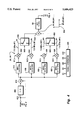
- FIG. 4 illustrates details of a preferred embodiment of the record portion of the video cassette recorder shown in FIG. 3;
- FIG. 5 illustrates details of the playback portion of the video cassette recorder shown in FIG. 3.
- FIG. 1a illustrates a typical RF energy spectrum for NTSC color television picture information recorded in the known VHS format using the well known color-under technique.
- the chrominance (chroma) information is recorded in quadrature as amplitude modulation 1 carried by, e.g., a 629 kHz color carrier.
- AM color sidebands extend outwardly from the color carrier by approximately 500 kHz on both sides thereof.
- Luminance information is recorded as frequency modulation 2 at a higher frequency.
- the synchronization (sync) tips are at about 3.4 MHz
- black level is at about 3.7 MHz
- white level is at about 4.4 MHz.
- a lower luminance sideband extends downwardly in frequency to about 1.2 MHz and an upper luminance sideband extends upwardly to about 6.4 MHz.
- the upper frequency end tends to be reduced in amplitude during playback, since its spectrum is a function of the characteristics of the particular magnetic tape medium, the recording/playback head, and the electronic circuitry of the particular VCR machine.
- the effective bandwidth during VCR playback is limited to about 200 to 250 lines, resulting in a noticeably degraded picture which is well below broadcast standards.
- One prior approach to improve VCR picture quality is to simply raise the FM carrier frequency used by the recorder in order to take advantage of the latest advances in magnetic media and recording heads, such as in the S-VHS recording format shown in FIG. 1b.
- This energy spectrum is substantially the same as that illustrated in FIG. 1a, however, the luminance carrier modulation is from 5.4 MHz for sync tips to 7.0 MHz for white level. Again, the upper end tends to be limited to about 8.5 MHz due to recording tape and hardware limitations.
- video tapes recorded in this format are incompatible with the standard VHS format and can only be used in S-VHS VCR's, thereby preventing the widespread use and popularity of this improved performance format.
- a new recording format having an augmentation channel for carrying high-frequency luminance signals in the tape bandwidth above the standard (low-frequency) luminance bandwidth, as shown in FIG. 2.
- the chrominance and low-frequency luminance information are AM and FM modulated, respectively, just as in the standard VHS format shown in FIG. 1a, however an augmentation carrier, at e.g., 7.5 MHz, is AM modulated with the high-frequency luminance portion of the NTSC video signal.
- the standard FM luminance channel is bandwidth limited to just over 6 MHz.
- the A-VHS format Since the chrominance and low-frequency luminance information are recorded in the same manner as the standard VHS format, the A-VHS format is completely backward compatible with standard VHS. Additionally, since the A-VHS format uses the same basic tape and heads as S-VHS, with only the addition of augmentation luminance carrier, an A-VHS recorder only requires an additional demodulator circuit and simple filtering to provide the improved picture performance over that of standard VHS, resulting in no increase in cost for an A-VHS recorder as compared to an S-VHS VCR. Furthermore, since A-VHS format recorders have high-frequency capability record/playback heads and use high-quality magnetic recording tape, they can simply include S-VHS circuitry for selectively playing back S-VHS tapes, if desired.
- FIG. 3 illustrates in simplified block diagram form the record and playback portions of a video cassette recorder for recording and playing back color television video signals in accordance with the principles of the invention.
- a source 10 of composite video signal such as an NTSC video signal
- C chrominance
- a luma/chroma separator 12 of conventional design.
- the chrominance component is processed and low pass filtered by a conventional chroma processor 14 and low pass filter (LPF) 16 for providing a conventional "color under" chroma signal to one input of an adder 18.
- LPF low pass filter
- a VHS type luminance component is developed by a 2.5 MHz LPF 19 which is then processed and FM modulated by a conventional luma processor 20 and FM modulator 22.
- a LPF 24 having a cut-off frequency of 6.5 MHz couples the modulated luminance component to a second input of adder 18.
- the high-frequency luminance component for the augmentation channel is obtained by subtracting-out the low-frequency luminance components by coupling the input and output of 2.5 MHz LPF 19 to first and second inputs, respectively, of a subtractor 28.
- the output of subtractor 28 comprises the NTSC luminance components between 2.5 MHz and 4.2 MHz.
- these high frequency luminance components are AM modulated on a carrier, such as a 7.5 MHz, signal, by a modulator 30 and applied, via a high pass filter (HPF) 32, to a third input of adder 18.
- a carrier such as a 7.5 MHz
- HPF high pass filter
- the amount of high-frequency luminance information included in the band-limited augmentation channel is maximized by using a bandwidth compression circuit 34 in the signal processing path before the AM modulator 30. It will be obvious to those skilled in the art of signal processing, that some of the input signals to adder 18 must be appropriately delayed to compensate for processing delays experienced in one other signal path.
- the output of adder 18 is applied to a tape record apparatus 36 (comprising record driver circuitry and record heads, not specifically shown) via which the signal spectrum shown in FIG. 2 is recorded on magnetic tape 38.
- a tape pick-up apparatus 40 (comprising pick-up heads and preamplifier circuitry, not specifically shown) recovers the FIG. 2 spectrum from magnetic tape 38. Due to the nature of the color-under signal, the chroma component is recovered in the standard manner using an appropriate LPF 42 and chroma processor 44, and then applied to a first input of an adder 46. The standard and augmentation channel luminance components are recovered using an appropriate HPF 48. From the output of HPF 48, a LPF 50 separates out the standard VHS luma component and applies it to one input of an adder 52. An appropriate (7.5 MHz) AM demodulator 54 recovers the high-frequency luma components from the augmentation channel, which are then applied to a second input of adder 52 after an appropriate bandwidth decompression which is complementary to that provided by bandwidth compression circuit 34.
- FIG. 4 details of the bandwidth compression and FM modulation circuits 34 and 30, respectively, of the augmentation channel are shown.
- the high-frequency luminance components from the output of subtractor 28 of FIG. 3 are applied to the input of a vertical low pass filter 400.
- Vertical LPF 400 comprises a 1-H delay line 410 and an adder 412 for averaging together time-sequential television line intervals of the video signal in a well known manner.
- the output of adder 412 is simultaneously coupled to the input of four parallel connected band pass filters (BPF's) 414, 416, 418 and 420 which provide at their outputs bandwidth spectrums, (in MHz), of B1 (2.5-2.9), B2 (2.9-3.3), B3 (3.3-3.7) and B4 (3.7-4.1), respectively.
- BPF's band pass filters
- Each band signal B1-B4 is then frequency shifted and AM modulated to the 7.5 MHz augmentation carrier frequency by a respective one of mixers 422, 424, 426 and 248, respectively, by application to respective ones of mixers 422-428 of an appropriate one of modulation signals S1, S2, S3 and S4, respectively.
- the frequency and phase of each of signals S1-S4 is selected so that modulated and frequency shifted band signals B1 and B2 become 90 degrees out of phase with band signals B3 and B4 at the outputs of their respective mixers, as shown in FIG. 4.
- a signal generator 429 generates signals S1-S4 using, e.g., conventional signal division techniques, so that signal S1-S4 comprise the frequencies (in MHz) of 5.0, 4.6, 4.2 and 3.8, respectively.
- a multiplexer 430 has band signals B1 and B2 coupled to its inputs, and a multiplexer 432 has band signals B3 and B4 coupled to its inputs. Multiplexer 430 and 432 are each driven by a one-half horizontal line-rate signal (H/2) for sequentially applying to an adder 434 quadrature modulated band signals B1, B3 during one horizontal line-time interval, and then B2, B4 during the next horizontal line-time interval.
- the quadrature-modulated line-sequential band signals are illustrated by vector diagram 436.
- BPF 32 cleans up the frequency spectrum provided at the output of adder 434 so as to select the double sideband, quadrature modulated, bandwidth compressed, augmentation channel signal, to comprise only the upper and lower first order sidebands of the
- the quadrature modulated augmentation channel signal from the output filter 48 is first demodulated from 7.5 MHz down to baseband using a 7.5 MHz signal source 510, a 90 degree phase shifter 512 and mixers 514 and 516.
- the line-sequential output of mixer 514 is band signals B1, B2, B1 . . . and the line-sequential output of mixer 516 is band signals B3, B4, B3 . . .
- the 1-H delay lines 518 and 520 are used to rearrange the line-sequential signals so that multiplexers 522, 524, 526 and 528 can each individually select only one of each of the band signals for later processing. That is, the band signal sequence at the output of mixer 514 is applied to the lower and upper inputs of multiplexers 522 and 524 and the band signal sequence at the output of 1-H delay line 518 is applied to the upper and lower inputs of multiplexers 522 and 524. Multiplexers 522 and 524 are each driven by a one-half horizontal line-time signal. Thus, the output of multiplexer 522 is always band signal B2 and the output of multiplexer 524 is always band signal B1.
- the band signal sequence at the output of mixer 516 is applied to the lower and upper inputs of multiplexers 526 and 528 and the band signal sequence at the output of 1-H delay line 520 is applied to the upper and lower inputs of multiplexers 526 and 528.
- Multiplexers 526 and 528 are each driven by a one-half horizontal line time signal.
- the output of multiplexer 526 is always band signal B4 and the output of multiplexer 528 is always band signal B3.
- Band signals B1-B4 are then shifted back to their proper position in the high-frequency luminance spectrum of 2.5 MHz-4.1 MHz by ixers 530, 532, 534 and 536, respectively having mixing signals (in MHz) of 2.5, 2.9, 3.3 and 3.7 applied thereto, respectively.
- BPF's 538, 540, 542 and 544 select the appropriate bandwidth, i.e., (in MHz) 2.5-2.9, 2.9-3.3, 3.3-3.7 and 3.7-4.1 from the outputs of mixers 530-536, respectively.
- An adder 546 combines the outputs of BPF's 538-544 for recreating the original high-frequency luminance spectrum of 2.5 MHz-4.1 MHz. Again it should be mentioned that all signals must be appropriately delayed to compensate for processing delays for the individual band signals.
- Another method would be to compress about 2 MHz of the high-frequency part of the luminance signal into a smaller band of horizontal frequency, such as 500 kHz, by vertically and temporally low pass filtering of the signal, and then recording 500 kHz parts of the high frequency spectrum sequentially on alternating lines and in alternating fields.
- HDTV type compression could be used, such as Discreet Cosine Transforms (DCT), with the possibility that HDTV might be recorded and reproduced with this new recording format.
- sub-coding or transform coding method of bandwidth compression can be used.
Landscapes
- Engineering & Computer Science (AREA)
- Signal Processing (AREA)
- Multimedia (AREA)
- Television Signal Processing For Recording (AREA)
Priority Applications (5)
| Application Number | Priority Date | Filing Date | Title |
|---|---|---|---|
| US07/599,566 US5606423A (en) | 1990-10-18 | 1990-10-18 | Compatible high-resolution video recording format |
| KR1019910003389A KR930005813B1 (ko) | 1990-10-18 | 1991-02-28 | 호환성을 갖는 고-해상도 비디오 기록포맷 |
| JP3267904A JPH0793732B2 (ja) | 1990-10-18 | 1991-10-16 | 互換性を有する高解像度ビデオ記録方法及び装置 |
| GB9122047A GB2252004A (en) | 1990-10-18 | 1991-10-17 | Video recording format |
| DE4134536A DE4134536C2 (de) | 1990-10-18 | 1991-10-18 | Verfahren und Vorrichtung zum Aufzeichnen von Videosignalen |
Applications Claiming Priority (1)
| Application Number | Priority Date | Filing Date | Title |
|---|---|---|---|
| US07/599,566 US5606423A (en) | 1990-10-18 | 1990-10-18 | Compatible high-resolution video recording format |
Publications (1)
| Publication Number | Publication Date |
|---|---|
| US5606423A true US5606423A (en) | 1997-02-25 |
Family
ID=24400148
Family Applications (1)
| Application Number | Title | Priority Date | Filing Date |
|---|---|---|---|
| US07/599,566 Expired - Lifetime US5606423A (en) | 1990-10-18 | 1990-10-18 | Compatible high-resolution video recording format |
Country Status (5)
| Country | Link |
|---|---|
| US (1) | US5606423A (ko) |
| JP (1) | JPH0793732B2 (ko) |
| KR (1) | KR930005813B1 (ko) |
| DE (1) | DE4134536C2 (ko) |
| GB (1) | GB2252004A (ko) |
Cited By (2)
| Publication number | Priority date | Publication date | Assignee | Title |
|---|---|---|---|---|
| US6014492A (en) * | 1996-02-07 | 2000-01-11 | Lg Electronics Inc. | Video signal recording and reproducing apparatus for digital video cassette tape recorder |
| US6925244B1 (en) | 1999-06-28 | 2005-08-02 | Samsung Electronics Co., Ltd | Apparatus for recording/reproducing high resolution video signal |
Families Citing this family (3)
| Publication number | Priority date | Publication date | Assignee | Title |
|---|---|---|---|---|
| US5822490A (en) * | 1990-05-31 | 1998-10-13 | Samsung Electronics Co., Ltd. | Apparatus and method for color-under chroma channel encoded with a high frequency luminance signal |
| KR950011521B1 (ko) * | 1992-03-20 | 1995-10-05 | 삼성전자주식회사 | 영상신호 중첩 및 펼침회로 |
| GB2330970A (en) * | 1997-10-31 | 1999-05-05 | Silverstone Holdings Limited | Bandwidth compression of a colour television signal |
Citations (7)
| Publication number | Priority date | Publication date | Assignee | Title |
|---|---|---|---|---|
| EP0070154A2 (en) * | 1981-07-09 | 1983-01-19 | British Broadcasting Corporation | Colour television systems |
| US4520385A (en) * | 1982-06-11 | 1985-05-28 | U.S. Philips Corporation | Television transmission system |
| JPS62257292A (ja) * | 1986-04-30 | 1987-11-09 | Victor Co Of Japan Ltd | 多重化情報信号記録再生方法及びその記録装置 |
| JPS6313490A (ja) * | 1986-07-03 | 1988-01-20 | Victor Co Of Japan Ltd | 多重化情報信号記録再生方法及びその記録装置 |
| US4743978A (en) * | 1985-12-10 | 1988-05-10 | Kabushiki Kaisha Toshiba | Recording/reproduction system with a fine picture quality for a helical scan-type video tape recorder |
| US4812920A (en) * | 1986-07-07 | 1989-03-14 | Canon Kabushiki Kaisha | Wide band video signal recording apparatus |
| US4984093A (en) * | 1987-09-17 | 1991-01-08 | Deutsche Thomson-Brandt Gmbh | Video recorder with increased bandwidth recording |
Family Cites Families (1)
| Publication number | Priority date | Publication date | Assignee | Title |
|---|---|---|---|---|
| JP2830689B2 (ja) * | 1993-04-28 | 1998-12-02 | 東陶機器株式会社 | 水 栓 |
-
1990
- 1990-10-18 US US07/599,566 patent/US5606423A/en not_active Expired - Lifetime
-
1991
- 1991-02-28 KR KR1019910003389A patent/KR930005813B1/ko not_active IP Right Cessation
- 1991-10-16 JP JP3267904A patent/JPH0793732B2/ja not_active Expired - Fee Related
- 1991-10-17 GB GB9122047A patent/GB2252004A/en not_active Withdrawn
- 1991-10-18 DE DE4134536A patent/DE4134536C2/de not_active Expired - Fee Related
Patent Citations (7)
| Publication number | Priority date | Publication date | Assignee | Title |
|---|---|---|---|---|
| EP0070154A2 (en) * | 1981-07-09 | 1983-01-19 | British Broadcasting Corporation | Colour television systems |
| US4520385A (en) * | 1982-06-11 | 1985-05-28 | U.S. Philips Corporation | Television transmission system |
| US4743978A (en) * | 1985-12-10 | 1988-05-10 | Kabushiki Kaisha Toshiba | Recording/reproduction system with a fine picture quality for a helical scan-type video tape recorder |
| JPS62257292A (ja) * | 1986-04-30 | 1987-11-09 | Victor Co Of Japan Ltd | 多重化情報信号記録再生方法及びその記録装置 |
| JPS6313490A (ja) * | 1986-07-03 | 1988-01-20 | Victor Co Of Japan Ltd | 多重化情報信号記録再生方法及びその記録装置 |
| US4812920A (en) * | 1986-07-07 | 1989-03-14 | Canon Kabushiki Kaisha | Wide band video signal recording apparatus |
| US4984093A (en) * | 1987-09-17 | 1991-01-08 | Deutsche Thomson-Brandt Gmbh | Video recorder with increased bandwidth recording |
Cited By (2)
| Publication number | Priority date | Publication date | Assignee | Title |
|---|---|---|---|---|
| US6014492A (en) * | 1996-02-07 | 2000-01-11 | Lg Electronics Inc. | Video signal recording and reproducing apparatus for digital video cassette tape recorder |
| US6925244B1 (en) | 1999-06-28 | 2005-08-02 | Samsung Electronics Co., Ltd | Apparatus for recording/reproducing high resolution video signal |
Also Published As
| Publication number | Publication date |
|---|---|
| KR920017074A (ko) | 1992-09-26 |
| DE4134536C2 (de) | 1994-04-07 |
| JPH0793732B2 (ja) | 1995-10-09 |
| DE4134536A1 (de) | 1992-04-30 |
| GB9122047D0 (en) | 1991-11-27 |
| JPH04271696A (ja) | 1992-09-28 |
| GB2252004A (en) | 1992-07-22 |
| KR930005813B1 (ko) | 1993-06-25 |
Similar Documents
| Publication | Publication Date | Title |
|---|---|---|
| US4831463A (en) | Video processing in which high frequency luminance components are folded into a mid-band spectrum | |
| US5576837A (en) | Digital modulators for use with sub-nyquist sampling of raster-scanned samples of image intensity | |
| JPS6043719B2 (ja) | カラ−像信号変換方式 | |
| US6253022B1 (en) | Video signal encoded with additional detail information | |
| US5223944A (en) | Method and apparatus for transmitting video signals during first and second portions thereof | |
| US5606423A (en) | Compatible high-resolution video recording format | |
| CA1334686C (en) | Video signal recording/reproducing apparatus | |
| KR920010167B1 (ko) | 영상신호 중첩 및 펼침회로 | |
| JPH06500438A (ja) | 付加信号を有するテレビジョン信号のためのビデオレコーダ | |
| US5465158A (en) | Video tape recorder capable of recording and reproducing wide-band chrominance signal | |
| JPH0195692A (ja) | 磁気記録再生装置 | |
| JP2702949B2 (ja) | Edtv用画像記録装置 | |
| JP2569584B2 (ja) | カラ−映像信号変換方法 | |
| JPS60163592A (ja) | 映像信号処理回路 | |
| JP3330264B2 (ja) | Secam信号再生処理装置 | |
| JPS63135077A (ja) | Vtr装置 | |
| JPS60241390A (ja) | 映像信号記録再生装置 | |
| JPH04267692A (ja) | ビデオ信号処理システム及びその処理方法 | |
| JPS6318915B2 (ko) | ||
| JPS61263391A (ja) | ビデオ信号記録装置 | |
| JPH05207512A (ja) | カラー映像信号の記録方式 | |
| JPS58225790A (ja) | テレビジョン信号記録再生装置 | |
| JPH0556396A (ja) | 狭帯域媒体を通じて広帯域幅のビデオ信号を記録および再生するためのシステム | |
| JPH03178291A (ja) | 映像信号の記録・再生方法 | |
| JPS6238917B2 (ko) |
Legal Events
| Date | Code | Title | Description |
|---|---|---|---|
| AS | Assignment |
Owner name: SAMSUNG ELECTRONICS CO., LTD. 416 MAETAN-DONG, SUW Free format text: ASSIGNMENT OF ASSIGNORS INTEREST.;ASSIGNOR:WEDAM, WERNER F.;REEL/FRAME:005538/0364 Effective date: 19901029 |
|
| STCF | Information on status: patent grant |
Free format text: PATENTED CASE |
|
| FEPP | Fee payment procedure |
Free format text: PAYOR NUMBER ASSIGNED (ORIGINAL EVENT CODE: ASPN); ENTITY STATUS OF PATENT OWNER: LARGE ENTITY |
|
| FPAY | Fee payment |
Year of fee payment: 4 |
|
| FPAY | Fee payment |
Year of fee payment: 8 |
|
| FPAY | Fee payment |
Year of fee payment: 12 |