US5163041A - Signal branching method applied to a protection switching equipment provided in a drop-insert station of a transmission system - Google Patents
Signal branching method applied to a protection switching equipment provided in a drop-insert station of a transmission system Download PDFInfo
- Publication number
- US5163041A US5163041A US07/598,240 US59824090A US5163041A US 5163041 A US5163041 A US 5163041A US 59824090 A US59824090 A US 59824090A US 5163041 A US5163041 A US 5163041A
- Authority
- US
- United States
- Prior art keywords
- line
- station
- signal
- drop
- terminal equipment
- Prior art date
- Legal status (The legal status is an assumption and is not a legal conclusion. Google has not performed a legal analysis and makes no representation as to the accuracy of the status listed.)
- Expired - Fee Related
Links
Images


Classifications
-
- H—ELECTRICITY
- H04—ELECTRIC COMMUNICATION TECHNIQUE
- H04B—TRANSMISSION
- H04B1/00—Details of transmission systems, not covered by a single one of groups H04B3/00 - H04B13/00; Details of transmission systems not characterised by the medium used for transmission
- H04B1/74—Details of transmission systems, not covered by a single one of groups H04B3/00 - H04B13/00; Details of transmission systems not characterised by the medium used for transmission for increasing reliability, e.g. using redundant or spare channels or apparatus
Definitions
- the present invention relates to a signal branching method applied to a protection switching equipment provided in a drop-insert station of a transmission system.
- a transmission system is for transmitting a users signal or data, which will be represented by a users signal hereinafter, through a transmission line starting from one end station to another end station and providing a plurality of drop-insert stations between the end stations in series.
- the transmission line consists of a plurality of work lines through which the users signals are transmitted and a protection line for protecting the users signal from meeting with failure of transmission due to an accident such as disconnection of the work line.
- the protection line is also used for a liaison communication among the end and the drop-insert stations.
- a protection signal is constantly transmitted through the protection line.
- a dummy signal was expressly generated as the protection signal at the end stations and transmitted through the protection line.
- one of the users signals transmitted through one of the work lines has come to be used instead of the dummy signal. This is for decreasing the size and the costs of each END station.
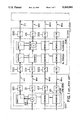
- FIG. 1 is a block diagram of a transmission system of the related art.
- the transmission system consists of a transmission line, END stations placed at the both ends of the transmission line and a plurality of drop-insert stations placed between the END stations in series on the transmission line.
- the transmission line includes a plurality of the work lines (WKs 1, 2, - - - n) and a protection line (PT).
- FIG. 1 shows a case that the users signals and a protection signal are transmitted from an end station (END STN) 100 to a drop-insert station (DI STN) 200 adjacent to END STN 100 through a plurality of work lines WK1, WK2, - - - WKn and a protection line (PT) respectively.
- END STN end station
- DI STN drop-insert station
- the END STN 100 includes a line terminal equipment (LTE) 120 for transmitting the protection signal to DI STN 200 through PT and for transmitting and receiving the liaison signals between END STN 100 and DI STN 200 respectively, and END STN 100 includes LTEs 121, 122, - - - for transmitting the users signals to DI STN 200 through WK1, WK2, - - - respectively.
- LTE line terminal equipment
- the DI STN 200 includes LTEs 220 for receiving the protection signal from END STN 100 and for transmitting and receiving the liaison signals transferring between END STN 100 and DI STN 200, and DI STN 200 also includes LTEs 221, 222, - - - for receiving the users signals sent from END STN 100 through WK1, WK2, - - -, and DI STN 200 further includes LTEs 230, 231, 232, - - - at the ends of PT, WK1, WK2, - - - between DI STN 200 and a succeeding DI STN same as LTEs 120, 121, - - - respectively.
- PSW protection switching equipment
- END STN 100 has PSW 101 and DI STN 200 has PSWs 201 and 202
- PSW 201 is a receiver side PSW (Rx-PSW)
- PSW 202 is a transmitter side PSW (Tx-PSW).
- the users signals given to END STN 100 are sent to LTEs 121, 122, - - - through a switch for WK1 (SW(WK1)), a switch for WK2 (SW(WK2)), - - - of PSW 101 in END STN 100, and the users signals arrived at LTEs 221, 222, - - - in DI STN 200 through WK1, WK2, - - - are sent to LTEs 231, 232, - - - in DI STN 200 through SWs(WK1) in Rx-PSW 201 and Tx-PSW 202, SWs(WK2) in Rx-PSW 201 and Tx-PSW 202 respectively, and the protection signal given to END STN 100 is sent to LTE 120 through a switch for PT (SW(PT)) in PSW 101, and the protection signal arrived at LTE 220 in DI
- FIG. 1 shows a case of using a users signal as the protection signal, so that in FIG. 1, a users signal being to be transmitted through WK1 branches at a hybrid circuit (H) in SW(WK1) to SW(PT) in PSW 101. Therefore, the users signals are transmitted through WK1, WK2, - - - and WKn as shown by thick solid lines and the one of the users signal, for instance, the users signal to be transmitted through WK1 is used as the protection signal as shown by a thick solid line marked by PT.
- WK1 has the disconnection trouble as shown by a mark "X" in FIG.
- PSWs in END STN 100 and DI STN 200 operates as follows: SW(PT) in PSW 101 operates so that the users signal to be transmitted through WK1 is transmitted through PT between END STN 100 and DI STN 200; and in PSW of DI STN 200, SWs(PT) in Rx-PSW 201 and Tx-PSW 202, SWs(WK1) in Rx-PSW 201 and Tx-PSW 202 operate so that the users signal transmitted to DI STN 200 through PT is sent to SW(PT) in Tx-PSW 202 through SW(PT) and SW(WK1) in Rx-PSW 201 and SW(WK1) in Tx-PSW 202 as shown by a dotted thick line in FIG. 1.
- FIG. 2 shows a case of transmitting the users signals from END STN 100 to DI STN 200, and FIG. 2 depicts only one users signal transmitted through WK1.
- PSW has a control unit such that PSW in an END STN has a control unit called a master control unit and PSW in a DI STN has a control unit called a slave control unit.
- the master control unit controls not only the own PSW in the END STN but also the slave control units in DI STNs over the transmission system, and control signals required to be sent among the master control unit and the slave control units are transferred through PTs provided between END STN and DI STN and between END STNs.
- PSW 11' in END STN 100 includes a master control unit (MASTER CONT) 150' and PSW 21" in DI STN 200 has a slave control unit (SLAVE CONT) 210".
- the END STN 100 includes a dummy generator (DUMMY GEN) 130 for generating a dummy signal to be transmitted through PT as the protection signal when no disconnection trouble occurs in WKs.
- DUMMY GEN dummy generator
- An SW(PT) 110' in PSW 11" includes two relays (RLY(11) and RLY(12)) and an SW(WK1) 111' in PSW 11' includes also two relays (RLY(13) and RLY(14)) so that the relays make connection as shown by a dotted line respectively when WKs have no disconnection trouble.
- PSW 21" in DI STN 200 has SW(PT) 211' including RLY(21) and RLY(22) and has SW(WK1) 212' including RLY(23) and RLY(24), making the relays connect circuits as shown by a dotted line respectively when WKs have no disconnection trouble.
- WKs have no disconnection trouble
- the dummy singal is transmitted through PTs and the users signals are transmitted through WKs (only WK1 is depicted in FIG. 2) in the transmission system.
- WKs only WK1 is depicted in FIG. 2
- LTE 221 in DI STN 200 detects that no users signal receives thereat and produces a detection signal for envoying the occurrence of the disconnection trouble to be sent to SLAVE CONT 210".
- SLAVE CONT 210" When SLAVE CONT 210" receives the detection signal, SLAVE CONT 210" sends the detection signal to MASTER CONT 150' through LTE 220, PT between DI STN 200 and END STN 100 and LTE 120.
- MASTER CONT 150' controls the own SW(PT) 110' and SW(WK1) 111' so that RLYs(11), (12), (13) and (14) make connection of circuits as shown in FIG. 2. After that, MASTER CONT 150' sends a command signal to SLAVE CONT 210" through LTE 120, PT and LTE 220.
- SLAVE CONT 210 controls SW(PT) 211' and SW(WK1) 212" so that RLYs(21, 22, 23 and 24) make connection of circuits as shown in FIG. 2.
- H/S INT hard soft interface
- the dummy signal from DUMMY GEN 130 is sent to LTE 121 but not sent to DI STN 21" because of the disconnection trouble, and the users signal to be sent to DI STN 200 through WK1 is switched to LTE 120 so as to be sent to DI STN 200 through PT, and in DI STN 200, the users signal sent to LTE 220 is switched to LTE 231 and sent to the succeeding DI STN through WK1 and an alarm signal produced in LTE 221 for envoying the occurrence of the disconnection trouble to the other stations is sent to LTE 230
- FIG. 3 is a case of using a users signal as the protection signal instead of the dummy signal. (The branch circuit of the users signal is not depicted in the figure.)
- the same reference numeral or symbol as in FIG. 2 designates the same unit as in FIG. 2, and FIG. 3 is also a case of transmitting the users signal from END STN to DI STN. Therefore, in FIG. 3, one of the users signals to be sent through WKs is sent to RLY(15) in SW(PT) 110 in PSW 11' of END STN 100.
- CONT 150 controls SW(PT) 110 and SW(WK1) 111 so that the relays in PSW 11' of END STN 100 and in PSW 21' of DI STN 200 make connection of circuits as shown by a dotted line in each relay.
- a users signal used as the protection signal is transmitted through PT and the users signal to be sent through WK1 is transmitted through WK1 straight from END STN 100 to the succeeding DI STN through DI STN 200 as shown in FIG. 3.
- MASTER CONT 150 After controlling the relays in PSW 11', MASTER CONT 150 sends a command signal to SLAVE CONT 210' in PSW 21' of DI STN 200.
- SLAVE CONT 210' receives the command signal from MASTER CONT 150, SLAVE CONT 210' controls SWs(PT) 211'(a) and 211'(b) and SWs(WK1) 212(a) and 212(b) so that the relays in the switches make contact as shown in FIG. 3.
- a users signal to be sent through WK1 branches at H1 in SW(WK1) 111 and is relayed to LTE 120 so that the users signal is sent to DI STN 200 through PT instead of WK1, and the protection signal (one of the users signals) is stopped from being sent to DI STN 200 by RLY(15) in SW(PT) 110 of PSW 11'.
- the alarm signal output from LTE 221 is stopped from being sent to LTE 2 30 by RLY(26) in SW(WK1) 212(a), and the users signal sent from END STN 100 through PT is received at LTE 220 and switched to LTE 231 by RLY(25) in SW(PT) 211'(a) and RLYs(26 and 27) in SW(WK1) 212(a).
- the users signal switched to LTE 231 branches to SW(PT) 211'(b) by H2 in SW(WK1) 212b and is relayed to LTE 230 by RLY(28) in SW(PT) 211'(b) so as to be used as a protection signal transmitted from DI STN 200 to the succeeding DI STN through PT.
- MASTER CONT 150 and SLAVE CONT 210' have a central processing unit (CPU) respectively. Using the CPU of MASTER CONT 150, MASTER CONT 150 controls not only the switches in PSW 11' of END STN 100 but also SLAVE CONT 210' by sending the command signal from MASTER CONT 150 to SLAVE CONT 210', and using the CPU in SLAVE CONT 210', SLAVE CONT 210' controls the switches in PSW 21' of DI STN 200.
- CPU central processing unit
- FIG. 4(a) shows a control flow chart of MASTER CONT 150 in FIG. 3. Because of software previously provided to CPU in MASTER CONT 150, MASTER CONT 150 operates as follows:
- MASTER CONT 150 when MASTER CONT 150 receives a detection signal envoying the occurrence of the disconnection trouble, MASTER CONT 150 searches where the detection signal comes from and recognizes that the signal comes from WK1 for instance (WHERE? WK1);
- MASTER CONT 150 controls RLYs(15) and (16) in PSW 11' of END STN 100 so as to make connection of circuits as shown in FIG. 3 and sends a command signal to SLAVE CONT 210' through LTE 120, PT and LTE 220 so that SLAVE CONT 210' controls RLYs(25), (26) and (27) so as to make connection of circuits as shown in FIG. 3 (RLYs(15, 16, 25, 26 and 27));
- MASTER CONT 150 polls SLAVE CONT 210' whether PT provided between DI STN 200 and the succeeding DI STN can be used for transmitting a users signal, polling whether a disconnection trouble occurs on the PT (PT OK?);
- MASTER CONT 150 asks whether the succeeding station is another END STN (END STN?);
- MASTER CONT 150 sends a command signal to SLAVE CONT 210' so that SLAVE CONT 210' controls RLY(29) so as to make connection of circuit as shown in FIG. 3 (RLY(29) ON);
- MASTER CONT 150 sends a command signal to SLAVE CONT 210' so that SLAVE CONT 210' controls RLY(28) so as to make connection of circuit as shown in FIG. 3 (RLY(28) ON);
- the control due to MASTER CONT 150 in FIG. 3 has been very complex, so that it has taken a lot of switching time when a disconnection trouble occurs in WK. Reducing the switching time is very important, because, if the switching time exceeds a designated time in the transmission system, the exceeding switching time would cause to stop the operation of other communication equipment such as an exchange equipment connected to the transmission system. How to reduce the switching time has been a problem in the protection switching equipment of the transmission system.
- an object of the present invention is to reduce the switching time wasted when a transmitting route of the users signal is switched from the work line to the protection line by the protection switching equipments in the end station and the drop-insert station of the transmission system when a work line for transmitting the users signal has the disconnection trouble.
- Another object of the present invention is to reduce the costs of the protection switching equipment, in particular, reducing the costs of software used to a CPU in each control unit of each protection switching equipment.
- Still another object of the present invention is to increase the operation reliability of the transmission system.
- the above objects of the present invention are achieved by connecting a line terminal equipment provided in the drop-insert station for receiving a signal from a preceding station of the drop-insert station through a protection line to another line terminal equipment provided in the drop-insert station for transmitting the signal to the succeeding station of the drop-insert station through another protection line, by an electrically connecting line provided in the protection switching equipment of the drop-insert station.
- the protection switching equipment is provided in the end station and the drop-insert stations respectively and has a CPU for controlling switches in the protection switching equipment.
- a master control unit provided in the end station controls not only the protection switching equipment in the end station but also the protection switching equipments in the drop-insert stations through slave control units in the drop-insert stations. Therefore, because of connecting the line terminal equipments in the drop-insert station by the connecting line, the amount of software used to a CPU in the master control unit of the end station can be reduced, which results in reducing the switching time.
- FIG. 1 is a block diagram of a transmission system, illustrating a principle of a signal branching method applied to a protection switching equipment provided in a drop-insert station of the transmission system of the related art;
- FIG. 2 is a block diagram of the transmission system of the prior art consisting of an end station including a protection switching equipment in which a dummy generator is provided for producing a dummy signal as a protection signal;
- FIG. 3 is a block diagram of the transmission system of the prior art using a users signal as the protection signal, instead of the dummy signal;
- FIG. 4(a) is a flow chart in which a master control unit in the protection switching equipment of the end station controls the protection switching equipments in the end station and the drop-insert stations, using a signal branching method of the prior art;
- FIG. 4(b) is a flow chart in which the master control unit controls the protection switching equipments in the end station and the drop-insert stations, using a signal branching method embodying the present invention
- FIG. 5 is a block diagram of the transmission system in which the protection switching equipment of the drop-insert station is improved so as to meet with the signal branching method embodying the present invention
- FIG. 6(a) is a block diagram of an internal circuit of the protection switching equipment controlled by the prior art method
- FIG. 6(b) is a block diagram of an internal circuit of the protection switching equipment controlled by the method embodying the present invention in a case where no disconnection trouble occurs on first preceding and succeeding work lines, looking from the drop-insert station;
- FIG. 6(c) is a block diagram of an internal circuit of the protection switching equipment controlled by the method embodying the present invention in any one of cases where a disconnection trouble occurs on the first preceding work line and where disconnection troubles occur on both the first preceding and succeeding work lines;
- FIG. 6(d) is a block diagram of an internal circuit of the protection switching equipment controlled by the method embodying the present invention in a case where a disconnection trouble occurs on the first succeeding work line.
- FIG. 5 is a block diagram of the transmission system using one of the users signals as the protection signal same as the transmission system described in reference to FIG. 3.
- the constitution of the block diagram in FIG. 5 is same as that in FIG. 3 except that PSW of DI STN is improved so as to meet with a signal branching method embodying the present invention.
- the same reference numeral or symbol as in FIG. 3 designates the same equipment, unit or part as in FIG. 3. Same as in FIG. 3, FIG.
- FIG. 5 shows a case of having a disconnection trouble on WK1, so that the users signal to be transmitted through WK1 branches to LTE 120 at END STN 100 for being transmitted to DI STN 200 through PT in accordance with the control of MASTER CONT 150.
- a disconnection trouble occurs on WK1 as marked by "X" in FIG. 5, same as described in reference to FIG. 3, the detection signal from LTE 221 in DI STN 200 is sent to SLAVE CONT 210 in DT STN 200 and sent to MASTER CONT 150 in END STN 100 from SLAVE CONT 210 through LTE 220, PT, LTE 120. Then, same as in FIG.
- MASTER CONT 150 controls own PSW 11 in END STN 100 so that RLYs(15) and (16) make connection of circuit as shown in FIG. 5, and MASTER CONT 150 sends a command signal to SLAVE CONT 210 so as to make SLAVE CONT 210 control the switches in PSW 21 in DI STN 200 as shown in FIG. 5.
- the output terminal of LTE 220 is connected to the input terminal of LTE 230 by a connecting line 250.
- Providing the connecting line 250 thus, additional elements are provided in PSW 21. That is, an RLY(30) is provided in SW(PT) 211(b) so that one contact of RLY(30) is connected to one contact of RLY(28). The other contact of RLY(30) is terminated by a resistor R3.
- a resistor R1 is provided on the connecting line 250 so that the output terminal of LTE 220 is connected to RLY(30) through R1.
- a contact of RLY(25), which is, in FIG. 3, connected to a contact of RLY(28), is terminated by R2.
- MASTER CONT 150 controls SLAVE CONT 210.
- SLAVE CONT 200 controls the switches in PSW 21 so that RLY(25) connects the output terminal of LTE 220 to R2, RLYs(30 and 28) connect the output terminal of LTE 220 to the input terminal of LTE 230 by the connecting line 250 including R1, RLY(26) connects the output terminal of LTE 221 to the input terminal of LTE 231 through H2 in SW(WK1) 212(b), and the branch output of H2 is disconnected to the input terminal of LTE 230 because of disconnecting contacts of RLY(29) and RLY(28).
- the protection signal sent from END STN 100 to DI STN 200 is sent to the succeeding STN of DI STN 200 through the connecting line 250, and the users signal sent from END STN 100 to DI STN 200 through WK1 is sent to the succeeding STN through H2.
- a circuit formed by RLYs in PSW 21 in case 1 is illustrated in FIG. 6(b).
- RLY(25) connects the output terminal of LTE 220 to R2
- RLY(26) connects the output terminal of LTE 221 to H2
- RLY(29) connects the branch users signal output of H2 to RLY(28)
- RLY(30) terminates the connecting line 250 by R3
- RLY(28) connects the input terminal of LTE 230 to RLY(29), so that the users signal to be transmitted through WK1 between DI STN 200 and the succeeding STN is switched to PT between DI STN 200 and the succeeding STN.
- a circuit in case 3 formed by RLYs in PSW 21 is illustrated in FIG. 6(d).
- R1, R2 and R3 are provided in consideration of impedance matching to LTEs 220 and 230, which will be easily understood by comparing FIGS. 6(b, c and d) with FIG. 6(a) which is a circuit in case of the prior art explained in reference to FIG. 3.
- FIG. 6(c) it will be understood by comparing FIG. 6(c) with FIG. 6(a) that R1 has resistance equivalent in impedance obtained by subtracting input impedance of LTE 230 from input impedance of the hybrid transistor circuit H2 of SW(wk1) 212(b) when the hybrid transistor circuit connected to LTE 230.
- MASTER CONT 150 operates in accordance with the control flow chart in FIG. 4(b), as follows:
- MASTER CONT 150 when MASTER CONT 150 receives a detection signal envoying the occurrence of the disconnection trouble, MASTER CONT 150 searches where the detection signal comes from and recognizes that the alarm signal comes from WK1 between END STN 100 and DI STN 200 (WHERE? WK1); and
- MASTER CONT 150 controls RLYs(15) and (16) in PSW 11 of END STN 100 so as to connect a circuit in PSW 11 as shown in FIG. 5 and sends a command signal to SLAVE CONT 210 through LTE 120, PT and LTE 220 so that SLAVE CONT 210 controls RLYs(25, 26, 27, 28, 29 and 30) so as to make a connecting circuit in PSW 21 as shown in FIG. 5 (RLYs(15, 16, 25, 26, 27, 28, 29 and 30)).
Landscapes
- Engineering & Computer Science (AREA)
- Computer Networks & Wireless Communication (AREA)
- Signal Processing (AREA)
- Small-Scale Networks (AREA)
Applications Claiming Priority (2)
| Application Number | Priority Date | Filing Date | Title |
|---|---|---|---|
| JP1-270686 | 1989-10-18 | ||
| JP1270686A JPH0795706B2 (ja) | 1989-10-18 | 1989-10-18 | 信号分岐方法 |
Publications (1)
| Publication Number | Publication Date |
|---|---|
| US5163041A true US5163041A (en) | 1992-11-10 |
Family
ID=17489539
Family Applications (1)
| Application Number | Title | Priority Date | Filing Date |
|---|---|---|---|
| US07/598,240 Expired - Fee Related US5163041A (en) | 1989-10-18 | 1990-10-16 | Signal branching method applied to a protection switching equipment provided in a drop-insert station of a transmission system |
Country Status (2)
| Country | Link |
|---|---|
| US (1) | US5163041A (ja) |
| JP (1) | JPH0795706B2 (ja) |
Cited By (10)
| Publication number | Priority date | Publication date | Assignee | Title |
|---|---|---|---|---|
| US5311501A (en) * | 1991-03-15 | 1994-05-10 | Fujitsu Limited | Routing system for linear add-drop multiplexer |
| US5412643A (en) * | 1991-03-29 | 1995-05-02 | Hitachi, Ltd. | Duplex field bus system |
| US5452286A (en) * | 1993-03-10 | 1995-09-19 | Fujitsu Limited | Digital transmission apparatus for subscribers having switching function from active transmission line to protection transmission line |
| US5479608A (en) * | 1992-07-17 | 1995-12-26 | Alcatel Network Systems, Inc. | Group facility protection in a digital telecommunications system |
| US5638358A (en) * | 1994-04-27 | 1997-06-10 | Nec Corporation | Protection switching system having impedance matching circuits |
| US5740157A (en) * | 1992-05-21 | 1998-04-14 | Alcatel Network Systems, Inc. | Distributed control methodology and mechanism for implementing automatic protection switching |
| US5978354A (en) * | 1995-07-21 | 1999-11-02 | Fujitsu Limited | Optical transmission system and transmission line switching control method |
| US6392992B1 (en) * | 1998-11-30 | 2002-05-21 | Nortel Networks Limited | Signal degrade oscillation control mechanism |
| US6735171B2 (en) * | 1998-07-28 | 2004-05-11 | Fujitsu Limited | SDH transmission system, SDH transmission equipment and line switching control method in SDH transmission system |
| US7099578B1 (en) | 1999-12-16 | 2006-08-29 | Tellabs Operations Inc. | 1:N protection in an optical terminal |
Citations (4)
| Publication number | Priority date | Publication date | Assignee | Title |
|---|---|---|---|---|
| US2802990A (en) * | 1953-08-04 | 1957-08-13 | Ericsson Telefon Ab L M | Switching system in multiple line multiplex transmission system |
| US3991278A (en) * | 1975-06-13 | 1976-11-09 | Bell Telephone Laboratories, Incorporated | Line protection switching system |
| US4393493A (en) * | 1980-11-10 | 1983-07-12 | International Telephone And Telegraph Corporation | Automatic protection apparatus for span lines employed in high speed digital systems |
| US4598399A (en) * | 1984-11-20 | 1986-07-01 | Rockwell International Corporation | Multichannel multisite signal protection channel switching apparatus |
-
1989
- 1989-10-18 JP JP1270686A patent/JPH0795706B2/ja not_active Expired - Lifetime
-
1990
- 1990-10-16 US US07/598,240 patent/US5163041A/en not_active Expired - Fee Related
Patent Citations (4)
| Publication number | Priority date | Publication date | Assignee | Title |
|---|---|---|---|---|
| US2802990A (en) * | 1953-08-04 | 1957-08-13 | Ericsson Telefon Ab L M | Switching system in multiple line multiplex transmission system |
| US3991278A (en) * | 1975-06-13 | 1976-11-09 | Bell Telephone Laboratories, Incorporated | Line protection switching system |
| US4393493A (en) * | 1980-11-10 | 1983-07-12 | International Telephone And Telegraph Corporation | Automatic protection apparatus for span lines employed in high speed digital systems |
| US4598399A (en) * | 1984-11-20 | 1986-07-01 | Rockwell International Corporation | Multichannel multisite signal protection channel switching apparatus |
Cited By (11)
| Publication number | Priority date | Publication date | Assignee | Title |
|---|---|---|---|---|
| US5311501A (en) * | 1991-03-15 | 1994-05-10 | Fujitsu Limited | Routing system for linear add-drop multiplexer |
| US5412643A (en) * | 1991-03-29 | 1995-05-02 | Hitachi, Ltd. | Duplex field bus system |
| US5740157A (en) * | 1992-05-21 | 1998-04-14 | Alcatel Network Systems, Inc. | Distributed control methodology and mechanism for implementing automatic protection switching |
| US5479608A (en) * | 1992-07-17 | 1995-12-26 | Alcatel Network Systems, Inc. | Group facility protection in a digital telecommunications system |
| US5452286A (en) * | 1993-03-10 | 1995-09-19 | Fujitsu Limited | Digital transmission apparatus for subscribers having switching function from active transmission line to protection transmission line |
| US5638358A (en) * | 1994-04-27 | 1997-06-10 | Nec Corporation | Protection switching system having impedance matching circuits |
| US5978354A (en) * | 1995-07-21 | 1999-11-02 | Fujitsu Limited | Optical transmission system and transmission line switching control method |
| US6735171B2 (en) * | 1998-07-28 | 2004-05-11 | Fujitsu Limited | SDH transmission system, SDH transmission equipment and line switching control method in SDH transmission system |
| US6392992B1 (en) * | 1998-11-30 | 2002-05-21 | Nortel Networks Limited | Signal degrade oscillation control mechanism |
| US7099578B1 (en) | 1999-12-16 | 2006-08-29 | Tellabs Operations Inc. | 1:N protection in an optical terminal |
| US7613392B2 (en) | 1999-12-16 | 2009-11-03 | Tellabs Operations, Inc. | 1:N protection in an optical terminal |
Also Published As
| Publication number | Publication date |
|---|---|
| JPH03132222A (ja) | 1991-06-05 |
| JPH0795706B2 (ja) | 1995-10-11 |
Similar Documents
| Publication | Publication Date | Title |
|---|---|---|
| US5105188A (en) | Method for initiating configuration of a communication network after the interruption of at least two-ring shaped networks arranged in parallel | |
| US5101405A (en) | Ring line concentrator | |
| US5163041A (en) | Signal branching method applied to a protection switching equipment provided in a drop-insert station of a transmission system | |
| EP0583798A1 (en) | Optical communication system having an improved protection line switching mechanism | |
| US5341418A (en) | ISDN terminal adapter for access from analog signal equipment of four-wire full duplex type to ISDN | |
| JPS61295800A (ja) | 遠隔局制御方式 | |
| EP0231907A2 (en) | Transmission control apparatus for duplex loop type transmission system | |
| US4985886A (en) | Transmission line branching device | |
| JP2568295B2 (ja) | 遠隔制御装置における制御出力協調装置 | |
| JP2664925B2 (ja) | 回線切替方式 | |
| JP3539868B2 (ja) | 遠隔監視システム | |
| JPS62123897A (ja) | 遠隔制御監視装置 | |
| JP2692267B2 (ja) | 伝送路切替回路 | |
| JPH06334733A (ja) | Isdn回線の端末te拡張装置 | |
| JPH0191547A (ja) | 共通バスシステム | |
| KR100237448B1 (ko) | 데이타 다중화 장치 및 방식 | |
| JP3057187B2 (ja) | 異種衛星システム間接続方式 | |
| JP3976399B2 (ja) | 回線接続装置 | |
| EP0159929A2 (en) | Hybrid high speed data bus | |
| JPH02199956A (ja) | 通信端末装置 | |
| JPS6258746A (ja) | 回線バツクアツプ方式 | |
| JPH0612900B2 (ja) | デ−タ伝送方式 | |
| JPH0626333B2 (ja) | 状態監視方法 | |
| JPS6243934A (ja) | デイジタル交換装置におけるマルチライン接続方式 | |
| JPH0374990B2 (ja) |
Legal Events
| Date | Code | Title | Description |
|---|---|---|---|
| AS | Assignment |
Owner name: FUJITSU LIMITED, JAPAN Free format text: ASSIGNMENT OF ASSIGNORS INTEREST.;ASSIGNOR:MORIYAMA, JUNICHI;REEL/FRAME:005486/0939 Effective date: 19901012 |
|
| FEPP | Fee payment procedure |
Free format text: PAYOR NUMBER ASSIGNED (ORIGINAL EVENT CODE: ASPN); ENTITY STATUS OF PATENT OWNER: LARGE ENTITY |
|
| FPAY | Fee payment |
Year of fee payment: 4 |
|
| REMI | Maintenance fee reminder mailed | ||
| LAPS | Lapse for failure to pay maintenance fees | ||
| FP | Lapsed due to failure to pay maintenance fee |
Effective date: 20001110 |
|
| STCH | Information on status: patent discontinuation |
Free format text: PATENT EXPIRED DUE TO NONPAYMENT OF MAINTENANCE FEES UNDER 37 CFR 1.362 |