US4967486A - Microwave assisted fluidized bed processor - Google Patents
Microwave assisted fluidized bed processor Download PDFInfo
- Publication number
- US4967486A US4967486A US07/367,766 US36776689A US4967486A US 4967486 A US4967486 A US 4967486A US 36776689 A US36776689 A US 36776689A US 4967486 A US4967486 A US 4967486A
- Authority
- US
- United States
- Prior art keywords
- fluidized bed
- microwave
- product
- expansion chamber
- microwave energy
- Prior art date
- Legal status (The legal status is an assumption and is not a legal conclusion. Google has not performed a legal analysis and makes no representation as to the accuracy of the status listed.)
- Expired - Lifetime
Links
- 238000012216 screening Methods 0.000 claims abstract description 5
- 239000000523 sample Substances 0.000 claims description 12
- 230000002441 reversible effect Effects 0.000 claims description 11
- 239000004809 Teflon Substances 0.000 claims description 10
- 229920006362 Teflon® Polymers 0.000 claims description 10
- 238000005243 fluidization Methods 0.000 claims description 9
- 230000008878 coupling Effects 0.000 claims description 6
- 238000010168 coupling process Methods 0.000 claims description 6
- 238000005859 coupling reaction Methods 0.000 claims description 6
- 230000005540 biological transmission Effects 0.000 claims description 5
- 238000012544 monitoring process Methods 0.000 claims description 5
- 239000007787 solid Substances 0.000 claims description 4
- 239000007789 gas Substances 0.000 description 18
- 238000001035 drying Methods 0.000 description 17
- LRUUNMYPIBZBQH-UHFFFAOYSA-N Methazole Chemical compound O=C1N(C)C(=O)ON1C1=CC=C(Cl)C(Cl)=C1 LRUUNMYPIBZBQH-UHFFFAOYSA-N 0.000 description 10
- 239000002245 particle Substances 0.000 description 10
- 239000000463 material Substances 0.000 description 9
- 238000012545 processing Methods 0.000 description 7
- 238000013461 design Methods 0.000 description 6
- 238000000034 method Methods 0.000 description 6
- 230000002457 bidirectional effect Effects 0.000 description 5
- 238000005469 granulation Methods 0.000 description 5
- 230000003179 granulation Effects 0.000 description 5
- 229910052751 metal Inorganic materials 0.000 description 5
- 230000008569 process Effects 0.000 description 5
- 229910001220 stainless steel Inorganic materials 0.000 description 5
- 239000010935 stainless steel Substances 0.000 description 5
- 238000009472 formulation Methods 0.000 description 4
- 239000002184 metal Substances 0.000 description 4
- 239000000203 mixture Substances 0.000 description 4
- 230000000644 propagated effect Effects 0.000 description 4
- XLYOFNOQVPJJNP-UHFFFAOYSA-N water Substances O XLYOFNOQVPJJNP-UHFFFAOYSA-N 0.000 description 4
- 229910052782 aluminium Inorganic materials 0.000 description 3
- XAGFODPZIPBFFR-UHFFFAOYSA-N aluminium Chemical compound [Al] XAGFODPZIPBFFR-UHFFFAOYSA-N 0.000 description 3
- 238000007906 compression Methods 0.000 description 3
- 230000006835 compression Effects 0.000 description 3
- 238000005516 engineering process Methods 0.000 description 3
- 239000011521 glass Substances 0.000 description 3
- 238000010438 heat treatment Methods 0.000 description 3
- 229920001296 polysiloxane Polymers 0.000 description 3
- 238000011160 research Methods 0.000 description 3
- IJGRMHOSHXDMSA-UHFFFAOYSA-N Atomic nitrogen Chemical compound N#N IJGRMHOSHXDMSA-UHFFFAOYSA-N 0.000 description 2
- 230000008901 benefit Effects 0.000 description 2
- 230000001143 conditioned effect Effects 0.000 description 2
- 230000007423 decrease Effects 0.000 description 2
- 230000001419 dependent effect Effects 0.000 description 2
- 230000005684 electric field Effects 0.000 description 2
- 238000002474 experimental method Methods 0.000 description 2
- 239000008187 granular material Substances 0.000 description 2
- 238000003780 insertion Methods 0.000 description 2
- 230000037431 insertion Effects 0.000 description 2
- 230000035515 penetration Effects 0.000 description 2
- 239000000758 substrate Substances 0.000 description 2
- 238000012360 testing method Methods 0.000 description 2
- 229910001369 Brass Inorganic materials 0.000 description 1
- LFQSCWFLJHTTHZ-UHFFFAOYSA-N Ethanol Chemical compound CCO LFQSCWFLJHTTHZ-UHFFFAOYSA-N 0.000 description 1
- 229920000881 Modified starch Polymers 0.000 description 1
- 229920002472 Starch Polymers 0.000 description 1
- 230000009471 action Effects 0.000 description 1
- 239000000853 adhesive Substances 0.000 description 1
- 230000001070 adhesive effect Effects 0.000 description 1
- 239000012298 atmosphere Substances 0.000 description 1
- 230000002238 attenuated effect Effects 0.000 description 1
- 239000010951 brass Substances 0.000 description 1
- 239000001506 calcium phosphate Substances 0.000 description 1
- 229910000389 calcium phosphate Inorganic materials 0.000 description 1
- 235000011010 calcium phosphates Nutrition 0.000 description 1
- 239000001913 cellulose Substances 0.000 description 1
- 229920002678 cellulose Polymers 0.000 description 1
- 230000008859 change Effects 0.000 description 1
- 239000011248 coating agent Substances 0.000 description 1
- 238000000576 coating method Methods 0.000 description 1
- 238000004891 communication Methods 0.000 description 1
- 239000004020 conductor Substances 0.000 description 1
- 150000004683 dihydrates Chemical class 0.000 description 1
- 239000003814 drug Substances 0.000 description 1
- 229940079593 drug Drugs 0.000 description 1
- 230000007613 environmental effect Effects 0.000 description 1
- 238000001704 evaporation Methods 0.000 description 1
- 239000004744 fabric Substances 0.000 description 1
- 239000000835 fiber Substances 0.000 description 1
- 239000012530 fluid Substances 0.000 description 1
- 235000013305 food Nutrition 0.000 description 1
- 239000003292 glue Substances 0.000 description 1
- 239000003979 granulating agent Substances 0.000 description 1
- JEGUKCSWCFPDGT-UHFFFAOYSA-N h2o hydrate Chemical compound O.O JEGUKCSWCFPDGT-UHFFFAOYSA-N 0.000 description 1
- 230000006872 improvement Effects 0.000 description 1
- 238000009434 installation Methods 0.000 description 1
- 125000001449 isopropyl group Chemical group [H]C([H])([H])C([H])(*)C([H])([H])[H] 0.000 description 1
- 239000007788 liquid Substances 0.000 description 1
- 239000013528 metallic particle Substances 0.000 description 1
- 238000012986 modification Methods 0.000 description 1
- 230000004048 modification Effects 0.000 description 1
- 229910052757 nitrogen Inorganic materials 0.000 description 1
- 230000036961 partial effect Effects 0.000 description 1
- 239000011236 particulate material Substances 0.000 description 1
- 239000013618 particulate matter Substances 0.000 description 1
- 239000011148 porous material Substances 0.000 description 1
- 239000000843 powder Substances 0.000 description 1
- 230000003449 preventive effect Effects 0.000 description 1
- 230000001681 protective effect Effects 0.000 description 1
- 238000004626 scanning electron microscopy Methods 0.000 description 1
- 239000000565 sealant Substances 0.000 description 1
- 238000001228 spectrum Methods 0.000 description 1
- 239000008107 starch Substances 0.000 description 1
- 235000019698 starch Nutrition 0.000 description 1
- 239000000126 substance Substances 0.000 description 1
- 238000012546 transfer Methods 0.000 description 1
- QORWJWZARLRLPR-UHFFFAOYSA-H tricalcium bis(phosphate) Chemical compound [Ca+2].[Ca+2].[Ca+2].[O-]P([O-])([O-])=O.[O-]P([O-])([O-])=O QORWJWZARLRLPR-UHFFFAOYSA-H 0.000 description 1
Images


Classifications
-
- B—PERFORMING OPERATIONS; TRANSPORTING
- B01—PHYSICAL OR CHEMICAL PROCESSES OR APPARATUS IN GENERAL
- B01J—CHEMICAL OR PHYSICAL PROCESSES, e.g. CATALYSIS OR COLLOID CHEMISTRY; THEIR RELEVANT APPARATUS
- B01J8/00—Chemical or physical processes in general, conducted in the presence of fluids and solid particles; Apparatus for such processes
- B01J8/18—Chemical or physical processes in general, conducted in the presence of fluids and solid particles; Apparatus for such processes with fluidised particles
- B01J8/24—Chemical or physical processes in general, conducted in the presence of fluids and solid particles; Apparatus for such processes with fluidised particles according to "fluidised-bed" technique
- B01J8/42—Chemical or physical processes in general, conducted in the presence of fluids and solid particles; Apparatus for such processes with fluidised particles according to "fluidised-bed" technique with fluidised bed subjected to electric current or to radiations this sub-group includes the fluidised bed subjected to electric or magnetic fields
-
- B—PERFORMING OPERATIONS; TRANSPORTING
- B01—PHYSICAL OR CHEMICAL PROCESSES OR APPARATUS IN GENERAL
- B01J—CHEMICAL OR PHYSICAL PROCESSES, e.g. CATALYSIS OR COLLOID CHEMISTRY; THEIR RELEVANT APPARATUS
- B01J19/00—Chemical, physical or physico-chemical processes in general; Their relevant apparatus
- B01J19/08—Processes employing the direct application of electric or wave energy, or particle radiation; Apparatus therefor
- B01J19/12—Processes employing the direct application of electric or wave energy, or particle radiation; Apparatus therefor employing electromagnetic waves
- B01J19/122—Incoherent waves
- B01J19/126—Microwaves
-
- F—MECHANICAL ENGINEERING; LIGHTING; HEATING; WEAPONS; BLASTING
- F26—DRYING
- F26B—DRYING SOLID MATERIALS OR OBJECTS BY REMOVING LIQUID THEREFROM
- F26B3/00—Drying solid materials or objects by processes involving the application of heat
- F26B3/02—Drying solid materials or objects by processes involving the application of heat by convection, i.e. heat being conveyed from a heat source to the materials or objects to be dried by a gas or vapour, e.g. air
- F26B3/06—Drying solid materials or objects by processes involving the application of heat by convection, i.e. heat being conveyed from a heat source to the materials or objects to be dried by a gas or vapour, e.g. air the gas or vapour flowing through the materials or objects to be dried
- F26B3/08—Drying solid materials or objects by processes involving the application of heat by convection, i.e. heat being conveyed from a heat source to the materials or objects to be dried by a gas or vapour, e.g. air the gas or vapour flowing through the materials or objects to be dried so as to loosen them, e.g. to form a fluidised bed
-
- F—MECHANICAL ENGINEERING; LIGHTING; HEATING; WEAPONS; BLASTING
- F26—DRYING
- F26B—DRYING SOLID MATERIALS OR OBJECTS BY REMOVING LIQUID THEREFROM
- F26B3/00—Drying solid materials or objects by processes involving the application of heat
- F26B3/32—Drying solid materials or objects by processes involving the application of heat by development of heat within the materials or objects to be dried, e.g. by fermentation or other microbiological action
- F26B3/34—Drying solid materials or objects by processes involving the application of heat by development of heat within the materials or objects to be dried, e.g. by fermentation or other microbiological action by using electrical effects
- F26B3/343—Drying solid materials or objects by processes involving the application of heat by development of heat within the materials or objects to be dried, e.g. by fermentation or other microbiological action by using electrical effects in combination with convection
Definitions
- the present invention relates to a fluidized bed processor such as a fluidized bed dryer, coater, or agglomerator utilizing the application of microwave energy.
- a microwave generator is connected with a fluidized bed processor to direct microwave energy into the region of fluidization in variously-oriented directions to create a plurality of standing wave modes within the processor through which the fluidized particles move in random directions.
- Fluidized bed processors of the batch type, are well known in the prior art. Such fluidized bed processors are used for a variety of drying, coating and agglomerating operations.
- the fluidized bed processors include a fluidized bed vessel having a fluidizing gas inlet and a fluidizing gas outlet to enable the gas to fluidize the product being treated.
- One such fluidized bed processor, particularly useful for laboratory operations, is the Uni-Glatt (TM) processor wherein the fluidized bed vessel includes a product container, or loading bowl, for receiving the product to be treated, an expansion chamber disposed immediately above the product container, and a filter chamber connected to the opposite end of the expansion chamber.
- TM Uni-Glatt
- a product retaining screen is provided at the bottommost end of the product container to support the product to be fluidized and defines an air inlet for allowing the fluidized gas to be directed upwardly to fluidize the product to be treated.
- the gas is drawn upwards through the vessel and exits the fluidizing gas outlet at the upper region of the filter chamber.
- the fluidized bed is formed within the product container and the expansion chamber.
- the filter chamber includes filters for catching any particles that may be blown upwards and includes a mechanical shaking apparatus or other means to shake or vibrate the filter bag to remove any particles embedded therein during the operation.
- Fluidized bed processing such as fluidized bed drying
- the fluidizing gas typically heated air
- the drying time is dependent upon the mass of air flow and the amount of energy absorbed into the particulate material.
- moisture is evaporated from the surface of the particles relatively rapidly.
- the drying time falls after the surface moisture is removed.
- water or moisture removal is dependent upon capillary or diffusional action. This requires increasingly more energy as the percent of moisture decreases or, stated otherwise, as the distance from the dried surface to the moisture increases.
- the product which is usually a poor heat conductor, requires greater and greater energy input (higher temperatures) to maintain an adequate level of heat transfer to drive the liquid out to the surface of the particles.
- the drying rate falls due to the relatively poor energy efficiency.
- fluidized bed dryers in combination with microwave energy sources are known in the art. See, for example, U.S. Pat. Nos. 3,528,179 and 4,126,945. These systems seek to take advantage of microwave energy which penetrates, to a great extent, into the product. Microwave energy serves to drive the moisture in the center of the product to be treated toward the surface. Once driven to the surface, the fluidizing gas provides for removal of the evaporating surface moisture.
- the fluidizing bed vessel be shaped in the form of a waveguide, i.e., a traveling wave applicator.
- a product retaining screen which supports the product to be fluidized.
- Microwave energy is applied at one end of this waveguide and microwaves are propagated both above and below the product screen along the length of the waveguide.
- the opposite end of the waveguide includes load tubes to absorb microwave energy not absorbed by the product.
- the product supporting screen is positioned near this center line and thus the area beneath the screen must also serve as part of the waveguide. As a result, much of the microwave energy propagated along the waveguide length is propagated below the screen and, of course, below the product being fluidized thus providing for an inefficient use of the microwave energy.
- the present invention provides for a novel microwave assisted fluidized bed processor system, specifically a batch type processor system, capable of utilization with a wide variety of products to be treated.
- the system comprises a fluidized bed vessel having a fluidized gas inlet and a fluidized gas outlet with a product supporting plate or screen position adjacent the gas inlet for supporting the product to be fluidized.
- the vessel includes a microwave entranceway for imparting microwave energy to the interior of the vessel, above the product supporting element wherein at least a portion of the fluidized bed vessel defines a microwave cavity for enabling variously-oriented, reflected microwaves to substantially fill the interior of the vessel in the region of fluidization.
- the product supporting element serves as a microwave protective screen to prevent escape of microwave energy below the screen.
- the microwave delivery system between the generator and the vessel includes a tuner to match the generator to the load within the fluidized bed processor thus maximizing the energy to be absorbed by the fluidized bed product. Tuning enables maximization for a wide variety of products and thus provides flexibility to the system.
- Such a design enables existing fluidized bed processors to be easily retrofitted to accomodate microwave generation.
- the microwave energy applied to the processor can be tuned to maximize the absorbtion depending upon the product to be processed.
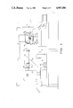
- FIG. 1 shows the overall microwave assisted fluidized bed processing system.
- FIG. 2 is a partial top or plan view of the system of FIG. 1.
- FIG. 3 depicts the coupling between the expansion chamber and the filter chamber.
- FIG. 4 depicts the microwave passage port, or microwave entranceway.
- FIG. 5 depicts the temperature probe within the expansion chamber.
- FIGS. 6(a)-(d) are graphs of the percent moisture versus time for four product formulations at various microwave energy inputs.
- the overall microwave assisted fluidized bed processing system of the present invention includes, generally, a fluidized bed unit 1 with associated control and display devices, a microwave generator 3 for generating microwave power, and a microwave delivery system 5 for delivering the microwaves to the fluidized bed unit.
- the specific system depicted utilizes a fluidized bed unit 1 sized for laboratory use, and thus is shown mounted on a work table 7.
- the present invention is by no means limited to the laboratory environment and, indeed, the invention encompasses the use of microwave assistance in all types of batch type fluidized bed processors including dryers, coaters, and agglomerators as are well known in the art.
- the invention is particularly appropriate for batch-type fluidized bed processors equipped to dry, granulate, or apply aqueous and nonaqueous films or powders to any substrate (food, drug, or nonfood substrates) and which permits heated or unheated, conditioned or non-conditioned, fluidizing gas, such as air or nitrogen, to enter and exit, or recirculate in, the fluidized bed unit.
- aqueous and nonaqueous films or powders to any substrate (food, drug, or nonfood substrates) and which permits heated or unheated, conditioned or non-conditioned, fluidizing gas, such as air or nitrogen, to enter and exit, or recirculate in, the fluidized bed unit.
- the fluidized bed unit 1 may be a basic laboratory size (approximately 1 kg) fluidized bed dryer/granulator.
- One such unit is the "Uni-Glatt" model no. 4245 distributed by the Glatt Air Techniques, Inc., but modified in a manner to be described to accomodate the introduction of microwave energy into the fluidized bed vessel.
- the fluidized bed unit 1 includes a fluidized bed vessel 9 and a control cabinet 11, both known in the art in their unmodified form.
- the control cabinet 11 includes a fluidizing gas fan or pump (not shown) to draw gas or air upwardly through the fluidized bed vessel 9 to form a fluidized bed of particulate matter to be treated in a manner well-known in the art.
- a heating coil 13 to heat the inlet air
- an inlet temperature probe 15 for detecting the temperature of the heated inlet air.
- An air inlet tube or pipe 17 enters into the control cabinet 11 and the air is supplied to the bottom of the vessel after being heated.
- An exhaust tube or pipe 19 is provided for receiving the air drawn from the top portion of the fluidized bed vessel; the pipe 19 extends downwardly into the cabinet 11 where the air is then exhausted or may be recirculated with the input air.
- An outlet temperature probe 21 is shown schematically for detecting the outlet air temperature.
- the fluidized bed vessel includes three (3) major components; a product container or loading bowl 23, an expansion chamber 25, and a filter chamber 27.
- the product retaining screen 29 supports or retains the product to be fluidized and includes sufficient openings to enable the inlet air, i.e., the fluidizing air, to be drawn therethrough and upward to fluidize the product.
- the product container 23 is removable from the expansion chamber 25 to enable the product to be treated to be loaded and to enable the treated product to be removed at the conclusion of the fluidizing process.
- the fluidized bed, or area of fluidization extends throughout the product container 23 and into substantially two-thirds the distance up into the expansion chamber 25.
- the filter chamber, or housing, 27 which includes therewithin a cloth filter bag (not shown) for preventing certain lightweight particles from escaping out of the fluidized bed vessel, and into the exhaust duct, and includes, preferably, a mechanical shaking apparatus (not shown) or other means for shaking or vibrating the filter bag to allow any entrained product to fall back into the fluidized bed.
- the exhaust air is drawn from the filter chamber through exhaust pipe or duct 19.
- the fluidized bed technology recognizes many modifications to the above-described basic system including a closed loop system wherein the exhaust air is recirculated to the inlet thus allowing no gas or air to escape into the environment and further recognizes a vacuum type arrangement wherein the fluidized bed components are maintained below atmospheric pressure.
- portions of the fluidized bed vessel act as a resonant cavity for microwave energy.
- the product container 23 and expansion chamber 25 define the cavity and must be metallic, such as stainless steel, for reflective purposes and must be relatively arc-free, i.e., must be smooth and without any burrs where arcing can occur resulting from the microwave energy imparted therein. That is, the cavity receiving the microwave energy must be an electrical continuum, i.e., an area that includes no non-conductive gaps which could cause arcing. Further, the cavity must be designed to prevent escape of microwave energy therefrom, both for environmental and safety reasons, as well as to prevent arcing.
- the vessel cavity at least the expansion chamber 25 where substantial fluidization takes place, be sufficiently sized to enable the microwave energy directed therein to be reflected at various angles so as to substantially fill the expansion chamber 25 with microwave energy.
- the variously reflected microwaves form standing waves of multiple modes within the expansion chamber. These modes are created by the variously reflected microwaves bouncing back and forth from the internal walls of the expansion chamber. These microwaves reinforce each other (increase in amplitude) in some areas and cancel each other out in other areas. Thus, a plurality of standing waves are created. The larger the cavity, the more opportunity for reflections and the greater opportunity for a standing wave pattern to be established.
- the expansion chamber 25 and the product container 23 are conically shaped. This conical shape enables the microwaves to bounce off the walls of the chambers with a vertical component to assist in substantially filling the chambers with microwave energy.
- the filter chamber 27 is coupled to the expansion chamber 25 through annular flanges 31, 33 that extend circumferentially around the two chambers.
- the annular flanges are bolted together (not shown). Clamped between the flanges is a microwave security screen 35 for preventing microwaves from escaping from the expansion chamber 25 into the filter chamber 27.
- This security screen 35 must have sufficient openings 37 to permit the fluidizing gas to be drawn therethrough. In the present case, it has been determined desirable that substantially 79% of the screen must be open to permit sufficient air flow.
- Microwave security screens are well-known in the art. As is well-known in such screen designs, there exists a relationship between the openings in the screen and the thickness of the screen to prevent microwave transmission therethrough.
- the security screen may be a metallic, such as stainless steel or aluminum, perforated plate 39, of non-woven flexible metallic meterial with one quarter inch hexagonal openings 37.
- the thickness of the plate is approximately one sixteenth inch.
- the openings 37 allow adequate microwave protection but do not inhibit sufficient air flow from the expansion chamber 25 to the filter chamber 27.
- the coupling arrangement as shown in FIG. 3 may be used.
- Two metallic rings 41, 43, of annular shape are welded to, and sandwich, the security screen 35 on opposite sides.
- These rings 41, 43 are of the same outer and inner diameter as the expansion chamber and flanges.
- the rings are metallic, such as stainless steel or aluminum, since such metallic elements do not transmit microwave energy.
- the rings also serve to keep the screen 35 secure.
- gaskets 45, 47 Disposed on opposite sides of the metallic rings are gaskets 45, 47.
- the flange 33 On the expansion chamber 25 side, the flange 33 includes a recess with an O-ring gasket 47; on the filter chamber 27 side is a rectangular annular gasket 45.
- These gaskets 45, 47 are compressible silicone gaskets with metallic particles, such as silver-plated aluminum, impregnated therein to provide an electrical continuum.
- One particular gasket material that may be used is made by Chomerics, identified by their Cho-Sil tradename.
- the gaskets 45, 47 are held in position by means of a special metal impregnated silicone-based adhesive known as Cho-Bond.
- the expansion chamber 25 is coupled to the product container 23 also through annular flanges 49, 51 is a manner known in the art.
- annular flanges 49, 51 In order to ensure an electrical continuum between the flanges 49, 51, an O-ring gasket of the same type of compressible material as the gasket 47 is bonded therebetween.
- the expansion chamber includes an annular recess for accomodating the O-ring (not shown). Again, the Cho-Bond brand glue is used to secure the gasket within the channel.
- the bottommost end of the product container 23, connected to an inlet gas duct 53 from the control cabinet 11 also includes an annular flange 55 coupled to a flange 57 on the duct 53.
- the product retaining screen 29 may be a woven dutch weave 100 mesh screen of the same type typically used in the Uni-Glatt system. Through observation, it was determined that this particular type of screen did not cause arcing by the microwave field.
- the screen 29 is designed to permit substantial air flow therethrough into the product container 23 and is sized to serve as a microwave security screen to prevent microwave energy from escaping.
- specialty gaskets, of electrically conductive impregnated material may be provided along with metallic O-rings bonded to the screen to maintain the electrical continuum.
- a viewing window 59 is provided in the expansion chamber 25 to enable the operator to view the fluidized bed process.
- the viewing window 59 includes a glass window that is sandwiched between the wall of the expansion chamber and a metallic annular plate 61 to retain the glass in a position over a circular opening in the chamber wall.
- a security screen 63 In order to maintain the use of a viewing window when adapting the fluidized bed vessel to receive microwave energy, a security screen 63 must be positioned adjacent the window to prevent the escape of microwave energy, as is well-known in the microwave heating or drying art.
- the security screen 63 which may be of the same general dimensions as discussed above, is cut to a diameter slightly larger than the diameter of the glass window and the metallic plate 61 that secures the window also secures the security screen.
- the plate 61 is in contact with the screen 63, which is, in turn, in contact with the wall of the vessel to maintain an electrical continuum.
- Silicone should preferably be used as a sealant to maintain an air tight fitting and to maintain the metal-to-metal contact between the screen 63, metal retaining ring 61, and vessel 25.
- a microwave entranceway 65 must be provided in the wall of the fluidized bed vessel, preferably in the expansion chamber 25 to maximize the reflections of microwave energy and increase the number of modes within the vessel.
- a circular hole 67 is drilled in the expansion chamber 25 wall, approximately two-thirds the way up toward the filter chamber 27. Although only one microwave entranceway 65 is depicted, it should be apparent that a plurality of entranceways, disposed at predetermined angles from each other around the entire periphery of the expansion chamber 25 may be provided.
- a stainless steel pipe 69 is welded to the exterior of the expansion chamber 25 having an appropriate annular flange 71 for connection with the microwave delivery system to be described below.
- a solid Teflon plug 73 is firmly positioned within the pipe and fills the microwave entranceway.
- Teflon is chosen because of its inertness, machinability and its ability to permit microwaves to propagate with little distortion.
- the plug 73 is milled from a solid block of Teflon to close tolerances so as to provide a snug circular contoured fit to conform to the shape and curvature of the expansion chamber 25.
- the Teflon plug, on the expansion chamber internal side, is contoured to match the curvature of the expansion chamber 25 and extends cylindrically into the metallic tube or pipe 69 a sufficient distance.
- a hole (not shown) may be tapped through the pipe 69 and into the Teflon block 73 to accomodate insertion of a Teflon bolt (not shown) to inhibit any rotation of the Teflon plug 73. It should be noted that the surfaces and joints of the pipe should be finely ground and polished to produce a sanitary and arc-free design.
- thermocouple probe 75 In order to monitor the temperature of the fluidized product, a probe, preferably a thermocouple probe 75 is provided through the walls of the expansion chamber 25. (Other types of probes may be used, such as fiber optic probes.)
- One such thermocouple probe that may be used is a cylindrical, type K, bimetal probe (model no. N8439 of Cole-Palmer Electronics).
- the probe 75 is an eighth inch outer diameter and twelve inches in length.
- the probe 75 may be connected to a read-out device such as a digital thermometer 77.
- the connecting cable 79 between the probe 75 and the thermometer 77 may be wrapped in metallic tape to minimize any interference that may occur at very low microwave power ranges.
- thermocouple probe 75 is inserted into a stainless steel protection tube 81 welded to the lower quadrant of the expansion chamber 25 and disposed inwardly into th expansion chamber.
- a conventional compression fitting 83 such as a National Pipe Thread (NPT) compression fitting, which provides a secure and precise penetration depth for the thermocouple probe 75 within the protection tube 81.
- NPT National Pipe Thread
- This NPT compression fitting 83 well-known in the art, not only provides immobilization of the temperature probe 75, but it ensures the necessary electrical continuum inside the microwave drying area.
- a locking nut 85 is provided to secure the probe in position.
- thermocouple probe 75 it is necessary that the thermocouple probe 75 be positioned at a precise penetration depth, determined experimentally, to enable accurate temperature readings.
- the positioning can be determined experimentally as follows. By providing a one liter load of water in the product loading container 23, and an input of 100 watts of microwave power, the position of the thermocouple probe 75 can be adjusted to varying depths until a low fluctuating and "true" reading is obtained.
- the "true" temperature is that temperature within the expansion chamber without the microwave energy.
- a microwave generator 3 of conventional design, is depicted.
- the microwave generator is manufactured by Associated Sciences Research Foundation, Inc., model no. RES 131, and is designed to provide a variable power output from 0 to approximately 1300 watts.
- the frequency provided by the generator 3 is a constant 2450 MHz (plus or minus 15 MHz)
- any standard microwave generator, or series of generators, with constant or variable energy output may be used.
- Variable energy output may be provided in a number of different ways. For example, variable energy output may be provided by a rheostat which changes the voltage applied to a magnetron within the microwave generator 3 and therefore changes the power wattage that the generator 3 may provide.
- Variable energy may also be attained by using a plurality of constant and/or variable energy microwave generators that may be selectively actuated to achieve different total energy input into the fluidized bed processor.
- the plurality of microwave generators may be connected to a single microwave delivery system 5, as will be described below, or separate microwave generators may be connected with separate delivery systems coupled to separate microwave entranceways.
- the microwaves generated by the microwave generator 3 are applied to the fluidized bed vessel via a microwave delivery system 5.
- the microwave delivery system 5 includes, first, a bidirectional coupler 91 (such as manufactured by Associated Sciences Research Foundation, Inc.).
- Bidirectional couplers 91 are well-known in the art and permit easy and rapid monitoring of the forward and reverse microwave energy. That is, the bidirectional coupler detects the forward power, i.e., the power provided into the expansion chamber 25 as well as the reverse power, i.e., the unused energy that is reflected back from the fluidized bed vessel.
- the reverse energy is that energy that is not absorbed by the product being treated.
- the forward coupler 93 may be equipped to provide minus 60 decibel attenuation and the reverse coupler 95 equipped to attenuate the signal by minus 50 decibel.
- the sensing and transference of the attenuated microwave energy may be via a temperature compensated thermistor and coaxial cable 97 connected to a power meter 99, such as a standard Hewlett-Packard power meter model no. 431 C.
- the temperature compensated thermistor (within the cable) and coaxial cable 97 may be model no. GIL- 360-2 manufactured by Struthers Electronics.
- the purpose of the forward coupler is to accurately measure the microwave power wattage into the fluidized bed processor. It is also used to calibrate and validate the microwave generator.
- the primary function of the reverse coupler is to measure the amount of reflected or unused microwave energy at any given time during the fluidizing process. It has been found that the reflected energy is proportional to the degree of dryness, of the material being processed. That is, during the initial stages of fluidized bed processing, substantially all of the microwave energy provided to the vessel is absorbed by the product. As the process continues, and the product gets dryer, less of the energy gets absorbed and thus more energy is reflected back out through the microwave entranceway 65, through the microwave delivery system 5, and is detected by the bidirectional coupler 91 and power meter 99.
- monitoring the reverse power one can determine the dryness of the material. That is, the higher the reverse power, the more energy is unabsorbed, which means that less moisture or water is present in the product material. Thus monitoring for the completion of the drying process may be made by monitoring the reverse energy out from the fluidizing bed vessel.
- a flexible waveguide 101 Connected to the bidirectional coupler 91 is a flexible waveguide 101.
- One such flexible waveguide 101 that may be used is a standard 18" flexible waveguide manufactured by Associated Sciences Research Foundation, Inc.
- the use of a flexible waveguide 101 is desirable to enable an easier installation by eliminating the painstaking job of perfectly levelling the microwave generator 3 and the fluidized bed processor 9.
- the flexible waveguide 101 is connected to a tuner, such as a slotted tuner 103 to be described.
- the flexible waveguide 101 may be of many configurations and may include twists, such as a 90° twist to orient the microwaves in particular directions into the fluidized bed vessel.
- twists such as a 90° twist to orient the microwaves in particular directions into the fluidized bed vessel.
- the flexible waveguide 101 and the slotted tuner 103 may be rotatable with respect to the flange 71 of the pipe 69 connected to the microwave entranceway to enable changing the orientation of the microwaves into the expansion chamber 25.
- the final component of the microwave delivery system is the tuner, which may be a slotted tuner 103, a well-known component.
- the slotted tuner 103 is a waveguide having a slot with a brass screw that moves within the slot to reflect energy back into the expansion chamber 25.
- the slotted tuner 103 permits adjustment to minimize the reverse power reflected out of the expansion chamber 25.
- the tuner 103 is used to match the microwave power input with the product load present in the fluidized bed processor. This is determined experimentally in advance of performing a processing operation for a particular type of product.
- Adjustment of the slotted tuner 103 is made prior to each process for a particular product formulation.
- a test load of the product formulation is provided within the product container 23, microwave energy is applied thereto, and the tuner 101 is adjusted to an optimum position to minimize the amount of reflected energy observed by the power meter.
- the inlet gas or air drawn or blown upwardly through the fluidized bed processor is provided via the inlet tube 17 having its free end in communication with the atmosphere. It is frequently desirable, particularly for test purposes, to be able to measure the volume of air drawn into the fluidized bed processor. Accordingly, the inlet air tube 17 may be a straight length of duct having an electronic vaned anemometer therein (not shown) for measuring the volume of air, in cubic feet per minute, in a manner well-known in the art.
- FIGS. 6(a)-(d) graphically represent the dramatic improvement of drying times for each formula at a 30° C. air inlet temperature. At the 30° C. air inlet temperature, in all cases, the final residual moisture specification could not be met without microwave assistance. Similar experiments on these product formulations were conducted at a 60° C. inlet air temperature. In the case where 60° C. air was employed, although moisture specifications were met in all cases, drying rates were improved 2 to 4 times with the input of microwave energy.
Landscapes
- Engineering & Computer Science (AREA)
- Chemical & Material Sciences (AREA)
- Microbiology (AREA)
- Life Sciences & Earth Sciences (AREA)
- General Engineering & Computer Science (AREA)
- Organic Chemistry (AREA)
- Chemical Kinetics & Catalysis (AREA)
- Health & Medical Sciences (AREA)
- Mechanical Engineering (AREA)
- Molecular Biology (AREA)
- Toxicology (AREA)
- Biomedical Technology (AREA)
- Combustion & Propulsion (AREA)
- Physics & Mathematics (AREA)
- Electromagnetism (AREA)
- General Health & Medical Sciences (AREA)
- Biotechnology (AREA)
- Drying Of Solid Materials (AREA)
- Physical Or Chemical Processes And Apparatus (AREA)
- Treatment Of Water By Ion Exchange (AREA)
- Devices And Processes Conducted In The Presence Of Fluids And Solid Particles (AREA)
- Medicines Containing Material From Animals Or Micro-Organisms (AREA)
- Coating Apparatus (AREA)
Priority Applications (6)
| Application Number | Priority Date | Filing Date | Title |
|---|---|---|---|
| US07/367,766 US4967486A (en) | 1989-06-19 | 1989-06-19 | Microwave assisted fluidized bed processor |
| DE90109880T DE69002882T2 (de) | 1989-06-19 | 1990-05-23 | Mikrowellenunterstützter Fliessbettprozessor. |
| AT90109880T ATE93609T1 (de) | 1989-06-19 | 1990-05-23 | Mikrowellenunterstuetzter fliessbettprozessor. |
| EP90109880A EP0403820B1 (de) | 1989-06-19 | 1990-05-23 | Mikrowellenunterstützter Fliessbettprozessor |
| DK90109880.6T DK0403820T3 (da) | 1989-06-19 | 1990-05-23 | Mikrobølgeunderstøttet behandlingsapparat med fluidiseret leje |
| JP2158883A JPH03143541A (ja) | 1989-06-19 | 1990-06-19 | マイクロ波使用の流動層処理装置 |
Applications Claiming Priority (1)
| Application Number | Priority Date | Filing Date | Title |
|---|---|---|---|
| US07/367,766 US4967486A (en) | 1989-06-19 | 1989-06-19 | Microwave assisted fluidized bed processor |
Publications (1)
| Publication Number | Publication Date |
|---|---|
| US4967486A true US4967486A (en) | 1990-11-06 |
Family
ID=23448506
Family Applications (1)
| Application Number | Title | Priority Date | Filing Date |
|---|---|---|---|
| US07/367,766 Expired - Lifetime US4967486A (en) | 1989-06-19 | 1989-06-19 | Microwave assisted fluidized bed processor |
Country Status (6)
| Country | Link |
|---|---|
| US (1) | US4967486A (de) |
| EP (1) | EP0403820B1 (de) |
| JP (1) | JPH03143541A (de) |
| AT (1) | ATE93609T1 (de) |
| DE (1) | DE69002882T2 (de) |
| DK (1) | DK0403820T3 (de) |
Cited By (32)
| Publication number | Priority date | Publication date | Assignee | Title |
|---|---|---|---|---|
| FR2669718A1 (fr) * | 1990-11-28 | 1992-05-29 | Basf Ag | Procede continu en couche turbulente pour le sechage avec menagement de produits humides sensibles a la temperature. |
| US5211808A (en) * | 1990-11-13 | 1993-05-18 | Savant Instruments | Microwave heating in a vacuum centrifugal concentrator |
| US5429665A (en) * | 1993-10-27 | 1995-07-04 | Botich; Leon A. | Apparatus for introducing microwave energy to desiccant for regenerating the same and method for using the same |
| US5509956A (en) * | 1994-07-08 | 1996-04-23 | Horizon Holdings, Inc. | Regenerative apparatus for recovery of volatiles |
| WO1998005418A1 (en) * | 1996-08-06 | 1998-02-12 | Emr Microwave Technology Corporation | Method and apparatus for microwave treatment of metal ores and concentrates in a fluidized bed reactor |
| US5849240A (en) * | 1993-11-23 | 1998-12-15 | Euro-Celtique, S.A. | Method of preparing sustained release pharmaceutical compositions |
| US5879705A (en) * | 1993-07-27 | 1999-03-09 | Euro-Celtique S.A. | Sustained release compositions of morphine and a method of preparing pharmaceutical compositions |
| US5891471A (en) * | 1993-11-23 | 1999-04-06 | Euro-Celtique, S.A. | Pharmaceutical multiparticulates |
| WO1999036582A1 (en) * | 1998-01-16 | 1999-07-22 | Emr Microwave Technology Corporation | Method for microwave induced oxidation of sulphidic ores and ore concentrates without the production of sulphur dioxide gas |
| US5958452A (en) * | 1994-11-04 | 1999-09-28 | Euro-Celtique, S.A. | Extruded orally administrable opioid formulations |
| US6063751A (en) * | 1996-05-14 | 2000-05-16 | The Procter & Gamble Company | Process for making a low density detergent composition by agglomeration followed by dielectric heating |
| US6068855A (en) * | 1994-11-03 | 2000-05-30 | Euro-Celtique S. A. | Pharmaceutical composition containing a fusible carrier and method for producing the same |
| WO2000050830A1 (en) * | 1999-02-26 | 2000-08-31 | Societe Des Produits Nestle S.A. | On-demand sauce or beverage heating system and method thereof |
| US6134807A (en) * | 1997-05-16 | 2000-10-24 | Tokyo Electron Limited | Drying processing method and apparatus using same |
| US20030143518A1 (en) * | 1994-11-18 | 2003-07-31 | Fraunhofer-Gesellschaft Zur Foerderung Der Angewandten Forschung E.V. | Method of drying blood plasma |
| US6789330B2 (en) | 1998-01-12 | 2004-09-14 | Invitrogen Corporation | Apparatus and method for drying solutions containing macromolecules |
| US20050089460A1 (en) * | 2003-10-28 | 2005-04-28 | Tranquilla James M. | Method of removing mercury from mercury contaminated materials |
| WO2006034553A1 (en) * | 2004-09-30 | 2006-04-06 | Technological Resources Pty. Limited | Microwave treatment of minerals |
| US7029632B1 (en) | 1999-10-06 | 2006-04-18 | Wacker-Chemie Gmbh | Radiation-heated fluidized-bed reactor |
| US20070257029A1 (en) * | 2006-05-02 | 2007-11-08 | Opperman Stephen H | Microwave heating system and method for removing volatiles from adsorbent materials |
| US20080069746A1 (en) * | 2006-09-20 | 2008-03-20 | Hw Advanced Technologies, Inc. | Method and apparatus for microwave induced pyrolysis of arsenical ores and ore concentrates |
| US20080069723A1 (en) * | 2006-09-20 | 2008-03-20 | Hw Advanced Technologies, Inc. | Method for oxidizing carbonaceous ores to facilitate precious metal recovery |
| US20080107570A1 (en) * | 2004-12-23 | 2008-05-08 | Collette Nv | Fluid Bed Apparatus Module and Method of Changing a First Module For a Second Module In a Fluid Bed Apparatus |
| US20080118421A1 (en) * | 2006-09-20 | 2008-05-22 | Hw Advanced Technologies, Inc. | Method and means for using microwave energy to oxidize sulfidic copper ore into a prescribed oxide-sulfate product |
| US20080148594A1 (en) * | 2006-12-22 | 2008-06-26 | Collette Nv | Continuous granulating and drying apparatus |
| CN100406567C (zh) * | 2002-01-22 | 2008-07-30 | 生物材料公司 | 生物可降解聚合物的干燥方法 |
| US20080233020A1 (en) * | 2007-03-15 | 2008-09-25 | Capital Technologies, Inc. | Processing apparatus with an electromagnetic launch |
| US7877895B2 (en) * | 2006-06-26 | 2011-02-01 | Tokyo Electron Limited | Substrate processing apparatus |
| US20120304482A1 (en) * | 2010-02-10 | 2012-12-06 | Casetech Gmbh | Method for drying flexible tubular casings by microwaves |
| US8557286B1 (en) | 1999-04-22 | 2013-10-15 | Euroceltique, S.A. | Method for producing a water-insoluble amorphous or partially amorphous controlled release matrix |
| DE102020127374A1 (de) | 2020-10-16 | 2022-04-21 | Technische Universität Bergakademie Freiberg | Verfahren zur Zersetzung eines Metall-Carbonats und/oder Metall-Hydroxids zu deren Metall-Oxid mittels Mikrowellen |
| WO2023096613A1 (en) * | 2021-11-23 | 2023-06-01 | Recep Tayyip Erdogan Universitesi | Fresh tea withering system with fluidized bed and microwave |
Families Citing this family (6)
| Publication number | Priority date | Publication date | Assignee | Title |
|---|---|---|---|---|
| DE4441167C1 (de) * | 1994-11-18 | 1996-03-14 | Fraunhofer Ges Forschung | Verfahren zur Trocknung von Blutplasma |
| JP2001517146A (ja) | 1997-03-27 | 2001-10-02 | グラツト ゲゼルシヤフト ミツト ベシユレンクテル ハフツング | 生産物の湿度を測定することにより、渦流流体層又は可動注入体内の顆粒化−、塊状化−、インスタント製品化−、コーティング−及び乾燥プロセス加工の監視及び/又は制御及び調整方法、並びに、前記方法を実施するためのエアエンジニアリング装置 |
| DE10260743B4 (de) * | 2002-12-23 | 2008-05-15 | Outokumpu Oyj | Verfahren und Anlage zum thermischen Behandeln von körnigen Feststoffen in einem Wirbelbett |
| DE10260741A1 (de) | 2002-12-23 | 2004-07-08 | Outokumpu Oyj | Verfahren und Anlage zur Wärmebehandlung von feinkörnigen Feststoffen |
| CN104383866A (zh) * | 2014-12-08 | 2015-03-04 | 华东理工大学 | 一种使用同轴裂缝天线的微波反应装置及其应用 |
| DE102015119358A1 (de) * | 2015-11-10 | 2017-05-11 | Axel GRAMMELSBERGER | Verfahren zum Trocknen von feuchten Substanzmengen durch Mikrowellen |
Citations (11)
| Publication number | Priority date | Publication date | Assignee | Title |
|---|---|---|---|---|
| US3235971A (en) * | 1963-03-01 | 1966-02-22 | Hammtronic S Systems Inc | Method and apparatus for drying |
| US3528179A (en) * | 1968-10-28 | 1970-09-15 | Cryodry Corp | Microwave fluidized bed dryer |
| US3555693A (en) * | 1968-09-27 | 1971-01-19 | Bangor Punta Operations Inc | Method and apparatus for treating pieces of material by microwaves |
| US3771234A (en) * | 1969-09-09 | 1973-11-13 | Exxon Research Engineering Co | Microwave drying process for synthetic polymers |
| US4037071A (en) * | 1976-04-19 | 1977-07-19 | Dca Food Industries Inc. | Method and apparatus for improved distribution of microwave power in a microwave cavity |
| US4055001A (en) * | 1971-11-18 | 1977-10-25 | Exxon Research & Engineering Co. | Microwave drying process for synthetic polymers |
| US4126945A (en) * | 1975-07-31 | 1978-11-28 | Gebrueder Buehler Ag | Method and apparatus for bulk material treatment |
| US4222176A (en) * | 1978-10-23 | 1980-09-16 | Tjurin Nikolai A | Method and apparatus for drying granulated dielectric materials |
| US4488362A (en) * | 1981-09-29 | 1984-12-18 | Siemens Aktiengesellschaft | Capacitive high-frequency drying apparatus |
| US4694133A (en) * | 1985-05-06 | 1987-09-15 | Nestec S. A. | Process and device for homogeneous microwave thermal treatment of liquid or solution in motion |
| US4714812A (en) * | 1985-05-08 | 1987-12-22 | John F. Woodhead, III | Apparatus and method for processing dielectric materials with microwave energy |
Family Cites Families (3)
| Publication number | Priority date | Publication date | Assignee | Title |
|---|---|---|---|---|
| JPS5745335A (en) * | 1980-09-02 | 1982-03-15 | Mitsui Eng & Shipbuild Co Ltd | Heating fluidized bed reactor |
| FR2562648B1 (fr) * | 1984-04-04 | 1988-05-27 | Valeo | Four de traitement thermique de produits solides dans des conditions de chauffage homogenes |
| KR880000618B1 (ko) * | 1985-12-28 | 1988-04-18 | 재단법인 한국화학연구소 | 초단파 가열 유동상 반응에 의한 고순도 다결정 실리콘의 제조 방법 |
-
1989
- 1989-06-19 US US07/367,766 patent/US4967486A/en not_active Expired - Lifetime
-
1990
- 1990-05-23 DE DE90109880T patent/DE69002882T2/de not_active Expired - Fee Related
- 1990-05-23 EP EP90109880A patent/EP0403820B1/de not_active Expired - Lifetime
- 1990-05-23 DK DK90109880.6T patent/DK0403820T3/da active
- 1990-05-23 AT AT90109880T patent/ATE93609T1/de not_active IP Right Cessation
- 1990-06-19 JP JP2158883A patent/JPH03143541A/ja active Pending
Patent Citations (11)
| Publication number | Priority date | Publication date | Assignee | Title |
|---|---|---|---|---|
| US3235971A (en) * | 1963-03-01 | 1966-02-22 | Hammtronic S Systems Inc | Method and apparatus for drying |
| US3555693A (en) * | 1968-09-27 | 1971-01-19 | Bangor Punta Operations Inc | Method and apparatus for treating pieces of material by microwaves |
| US3528179A (en) * | 1968-10-28 | 1970-09-15 | Cryodry Corp | Microwave fluidized bed dryer |
| US3771234A (en) * | 1969-09-09 | 1973-11-13 | Exxon Research Engineering Co | Microwave drying process for synthetic polymers |
| US4055001A (en) * | 1971-11-18 | 1977-10-25 | Exxon Research & Engineering Co. | Microwave drying process for synthetic polymers |
| US4126945A (en) * | 1975-07-31 | 1978-11-28 | Gebrueder Buehler Ag | Method and apparatus for bulk material treatment |
| US4037071A (en) * | 1976-04-19 | 1977-07-19 | Dca Food Industries Inc. | Method and apparatus for improved distribution of microwave power in a microwave cavity |
| US4222176A (en) * | 1978-10-23 | 1980-09-16 | Tjurin Nikolai A | Method and apparatus for drying granulated dielectric materials |
| US4488362A (en) * | 1981-09-29 | 1984-12-18 | Siemens Aktiengesellschaft | Capacitive high-frequency drying apparatus |
| US4694133A (en) * | 1985-05-06 | 1987-09-15 | Nestec S. A. | Process and device for homogeneous microwave thermal treatment of liquid or solution in motion |
| US4714812A (en) * | 1985-05-08 | 1987-12-22 | John F. Woodhead, III | Apparatus and method for processing dielectric materials with microwave energy |
Non-Patent Citations (2)
| Title |
|---|
| "Microwave Fluidized Bed Dryer", Microwave Power Symp., 10th Annu. Proc. Univ. of Waterloo, Ont., May 28-30, M. A. Rzepecka, M. A. Humid, 5/75, pp. 297-299. |
| Microwave Fluidized Bed Dryer , Microwave Power Symp., 10th Annu. Proc. Univ. of Waterloo, Ont., May 28 30, M. A. Rzepecka, M. A. Humid, 5/75, pp. 297 299. * |
Cited By (55)
| Publication number | Priority date | Publication date | Assignee | Title |
|---|---|---|---|---|
| US5211808A (en) * | 1990-11-13 | 1993-05-18 | Savant Instruments | Microwave heating in a vacuum centrifugal concentrator |
| FR2669718A1 (fr) * | 1990-11-28 | 1992-05-29 | Basf Ag | Procede continu en couche turbulente pour le sechage avec menagement de produits humides sensibles a la temperature. |
| US6143328A (en) * | 1993-07-27 | 2000-11-07 | Euro-Celtique, S.A. | Sustained release compositions and a method of preparing pharmaceutical compositions |
| US5879705A (en) * | 1993-07-27 | 1999-03-09 | Euro-Celtique S.A. | Sustained release compositions of morphine and a method of preparing pharmaceutical compositions |
| US5429665A (en) * | 1993-10-27 | 1995-07-04 | Botich; Leon A. | Apparatus for introducing microwave energy to desiccant for regenerating the same and method for using the same |
| US5965163A (en) * | 1993-11-23 | 1999-10-12 | Euro-Celtique, S.A. | Substained release compositions and a method of preparing pharmaceutical compositions |
| US5849240A (en) * | 1993-11-23 | 1998-12-15 | Euro-Celtique, S.A. | Method of preparing sustained release pharmaceutical compositions |
| US5891471A (en) * | 1993-11-23 | 1999-04-06 | Euro-Celtique, S.A. | Pharmaceutical multiparticulates |
| US6162467A (en) * | 1993-11-23 | 2000-12-19 | Euro-Celtique, S.A. | Sustained release compositions and a method of preparing pharmaceutical compositions |
| US5509956A (en) * | 1994-07-08 | 1996-04-23 | Horizon Holdings, Inc. | Regenerative apparatus for recovery of volatiles |
| US6068855A (en) * | 1994-11-03 | 2000-05-30 | Euro-Celtique S. A. | Pharmaceutical composition containing a fusible carrier and method for producing the same |
| US6743442B2 (en) | 1994-11-04 | 2004-06-01 | Euro-Celtique, S.A. | Melt-extruded orally administrable opioid formulations |
| US6706281B2 (en) | 1994-11-04 | 2004-03-16 | Euro-Celtique, S.A. | Melt-extrusion multiparticulates |
| US5965161A (en) * | 1994-11-04 | 1999-10-12 | Euro-Celtique, S.A. | Extruded multi-particulates |
| US5958452A (en) * | 1994-11-04 | 1999-09-28 | Euro-Celtique, S.A. | Extruded orally administrable opioid formulations |
| US6335033B2 (en) | 1994-11-04 | 2002-01-01 | Euro-Celtique, S.A. | Melt-extrusion multiparticulates |
| US6261599B1 (en) | 1994-11-04 | 2001-07-17 | Euro-Celtique, S.A. | Melt-extruded orally administrable opioid formulations |
| US7510727B2 (en) | 1994-11-04 | 2009-03-31 | Purdue Pharma L.P. | Melt-extrusion multiparticulates |
| US20030143518A1 (en) * | 1994-11-18 | 2003-07-31 | Fraunhofer-Gesellschaft Zur Foerderung Der Angewandten Forschung E.V. | Method of drying blood plasma |
| US6063751A (en) * | 1996-05-14 | 2000-05-16 | The Procter & Gamble Company | Process for making a low density detergent composition by agglomeration followed by dielectric heating |
| US6074533A (en) * | 1996-08-06 | 2000-06-13 | Emr Microwave Technology Corporation | Method and apparatus for optimization of energy coupling for microwave treatment of metal ores and concentrates in a microwave fluidized bed reactor |
| WO1998005418A1 (en) * | 1996-08-06 | 1998-02-12 | Emr Microwave Technology Corporation | Method and apparatus for microwave treatment of metal ores and concentrates in a fluidized bed reactor |
| US5972302A (en) * | 1996-08-27 | 1999-10-26 | Emr Microwave Technology Corporation | Method for the microwave induced oxidation of pyritic ores without the production of sulphur dioxide |
| US6134807A (en) * | 1997-05-16 | 2000-10-24 | Tokyo Electron Limited | Drying processing method and apparatus using same |
| US6789330B2 (en) | 1998-01-12 | 2004-09-14 | Invitrogen Corporation | Apparatus and method for drying solutions containing macromolecules |
| WO1999036582A1 (en) * | 1998-01-16 | 1999-07-22 | Emr Microwave Technology Corporation | Method for microwave induced oxidation of sulphidic ores and ore concentrates without the production of sulphur dioxide gas |
| WO2000050830A1 (en) * | 1999-02-26 | 2000-08-31 | Societe Des Produits Nestle S.A. | On-demand sauce or beverage heating system and method thereof |
| US6433320B2 (en) | 1999-02-26 | 2002-08-13 | Nestec S.A. | On-demand microwave heating system and method |
| AU762443B2 (en) * | 1999-02-26 | 2003-06-26 | Societe Des Produits Nestle S.A. | On-demand sauce or beverage heating system and method thereof |
| US8557286B1 (en) | 1999-04-22 | 2013-10-15 | Euroceltique, S.A. | Method for producing a water-insoluble amorphous or partially amorphous controlled release matrix |
| US7029632B1 (en) | 1999-10-06 | 2006-04-18 | Wacker-Chemie Gmbh | Radiation-heated fluidized-bed reactor |
| CN100406567C (zh) * | 2002-01-22 | 2008-07-30 | 生物材料公司 | 生物可降解聚合物的干燥方法 |
| US7214254B2 (en) * | 2003-10-28 | 2007-05-08 | Hendrix Holding Company, Inc. | Method of removing mercury from mercury contaminated materials |
| US20050089460A1 (en) * | 2003-10-28 | 2005-04-28 | Tranquilla James M. | Method of removing mercury from mercury contaminated materials |
| WO2006034553A1 (en) * | 2004-09-30 | 2006-04-06 | Technological Resources Pty. Limited | Microwave treatment of minerals |
| RU2389806C2 (ru) * | 2004-09-30 | 2010-05-20 | Текнолоджикал Ресорсиз Пти. Лимитед | Обработка минерального сырья микроволнами |
| US20090013822A1 (en) * | 2004-09-30 | 2009-01-15 | Technological Resources Pty | Microwave treatment of minerals |
| US7727301B2 (en) | 2004-09-30 | 2010-06-01 | Technological Resources Pty. Limited | Microwave treatment of minerals |
| US20080107570A1 (en) * | 2004-12-23 | 2008-05-08 | Collette Nv | Fluid Bed Apparatus Module and Method of Changing a First Module For a Second Module In a Fluid Bed Apparatus |
| US7727484B2 (en) * | 2004-12-23 | 2010-06-01 | Collette Nv | Fluid bed apparatus module and method of changing a first module for a second module in a fluid bed apparatus |
| US20070257029A1 (en) * | 2006-05-02 | 2007-11-08 | Opperman Stephen H | Microwave heating system and method for removing volatiles from adsorbent materials |
| US7498548B2 (en) | 2006-05-02 | 2009-03-03 | Ranger Research, Inc. | Microwave heating system and method for removing volatiles from adsorbent materials |
| US8181356B2 (en) | 2006-06-26 | 2012-05-22 | Tokyo Electron Limited | Substrate processing method |
| US7877895B2 (en) * | 2006-06-26 | 2011-02-01 | Tokyo Electron Limited | Substrate processing apparatus |
| US20080118421A1 (en) * | 2006-09-20 | 2008-05-22 | Hw Advanced Technologies, Inc. | Method and means for using microwave energy to oxidize sulfidic copper ore into a prescribed oxide-sulfate product |
| US20080069723A1 (en) * | 2006-09-20 | 2008-03-20 | Hw Advanced Technologies, Inc. | Method for oxidizing carbonaceous ores to facilitate precious metal recovery |
| US20080069746A1 (en) * | 2006-09-20 | 2008-03-20 | Hw Advanced Technologies, Inc. | Method and apparatus for microwave induced pyrolysis of arsenical ores and ore concentrates |
| US20080148594A1 (en) * | 2006-12-22 | 2008-06-26 | Collette Nv | Continuous granulating and drying apparatus |
| US7908765B2 (en) * | 2006-12-22 | 2011-03-22 | Collette Nv | Continuous granulating and drying apparatus |
| US20090179028A1 (en) * | 2007-03-15 | 2009-07-16 | Purta David A | Processing apparatus with an electromagnetic launch |
| US7518092B2 (en) | 2007-03-15 | 2009-04-14 | Capital Technologies, Inc. | Processing apparatus with an electromagnetic launch |
| US20080233020A1 (en) * | 2007-03-15 | 2008-09-25 | Capital Technologies, Inc. | Processing apparatus with an electromagnetic launch |
| US20120304482A1 (en) * | 2010-02-10 | 2012-12-06 | Casetech Gmbh | Method for drying flexible tubular casings by microwaves |
| DE102020127374A1 (de) | 2020-10-16 | 2022-04-21 | Technische Universität Bergakademie Freiberg | Verfahren zur Zersetzung eines Metall-Carbonats und/oder Metall-Hydroxids zu deren Metall-Oxid mittels Mikrowellen |
| WO2023096613A1 (en) * | 2021-11-23 | 2023-06-01 | Recep Tayyip Erdogan Universitesi | Fresh tea withering system with fluidized bed and microwave |
Also Published As
| Publication number | Publication date |
|---|---|
| JPH03143541A (ja) | 1991-06-19 |
| EP0403820B1 (de) | 1993-08-25 |
| DK0403820T3 (da) | 1994-01-10 |
| DE69002882T2 (de) | 1994-01-20 |
| DE69002882D1 (de) | 1993-09-30 |
| ATE93609T1 (de) | 1993-09-15 |
| EP0403820A1 (de) | 1990-12-27 |
Similar Documents
| Publication | Publication Date | Title |
|---|---|---|
| US4967486A (en) | Microwave assisted fluidized bed processor | |
| CA1300691C (en) | Heating and drying apparatus for moist fabric | |
| US5616268A (en) | Microwave blood thawing with feedback control | |
| EP2920533B1 (de) | Vorrichtung und verfahren zur entwässerung mittels mikrowellenstrahlung | |
| US6316759B2 (en) | Microwave heating apparatus for gas chromatographic columns | |
| JP4638045B2 (ja) | マイクロ波アシスト化学処理におけるシステム検出器用のキャビティ内のコネクタ | |
| JPH1089846A (ja) | 乾燥及び/又は結晶化装置 | |
| JPS58142184A (ja) | 乾燥装置 | |
| CA1228399A (en) | Water moisture measuring instrument and method | |
| Adu et al. | Effect of increasing hygroscopicity on the microwave heating of solid foods | |
| Ang et al. | Microwave freeze drying: an experimental investigation | |
| Doelling et al. | The development of a microwave fluid-bed processor. I. Construction and qualification of a prototype laboratory unit | |
| JP2650295B2 (ja) | 高周波乾燥装置 | |
| Cieslik et al. | Installation for concentrated uniform heating of objects by microwave radiation | |
| WO2004008809A1 (en) | Method and apparatus for controlling microwave energy transmitted to a fluidised bed | |
| JP2693176B2 (ja) | 加熱装置 | |
| JP2000356601A (ja) | 導波管内の結露防止装置 | |
| JP2024506562A (ja) | マイクロ波放射エネルギーを利用したaldプロセスのマイクロ波アシスト表面化学アニーリング用マイクロ波システム | |
| RU2816575C1 (ru) | Универсальный микроволновый комплекс для переработки каустобиолитов | |
| JPS5971290A (ja) | 高周波加熱装置 | |
| JPS58126772A (ja) | 解凍状況検出装置 | |
| JP2616717B2 (ja) | 電磁加熱処理装置 | |
| Toropainen | A new method for measuring properties of unhomogeneous materials using a two-polarization forward-scattering measurement | |
| JP2893478B2 (ja) | 粉粒体乾燥装置 | |
| JPS57111262A (en) | Surface treatment of scaly or powdery glass |
Legal Events
| Date | Code | Title | Description |
|---|---|---|---|
| AS | Assignment |
Owner name: GLATT AIR TECHNIQUES INC., 20 SPEAR ROAD, RAMSEY, Free format text: ASSIGNMENT OF ASSIGNORS INTEREST.;ASSIGNOR:DOELLING, MICHAEL K.;REEL/FRAME:005113/0316 Effective date: 19890615 |
|
| AS | Assignment |
Owner name: GLATT GMBH, A CORP. OF WEST GERMANY Free format text: ASSIGNMENT OF ASSIGNORS INTEREST.;ASSIGNOR:GLATT AIR TECHNIQUES, INC.;REEL/FRAME:005281/0350 Effective date: 19900320 |
|
| STCF | Information on status: patent grant |
Free format text: PATENTED CASE |
|
| FEPP | Fee payment procedure |
Free format text: PAYOR NUMBER ASSIGNED (ORIGINAL EVENT CODE: ASPN); ENTITY STATUS OF PATENT OWNER: LARGE ENTITY |
|
| FPAY | Fee payment |
Year of fee payment: 4 |
|
| FPAY | Fee payment |
Year of fee payment: 8 |
|
| FPAY | Fee payment |
Year of fee payment: 12 |