US4965620A - Camera - Google Patents
Camera Download PDFInfo
- Publication number
- US4965620A US4965620A US07/349,846 US34984689A US4965620A US 4965620 A US4965620 A US 4965620A US 34984689 A US34984689 A US 34984689A US 4965620 A US4965620 A US 4965620A
- Authority
- US
- United States
- Prior art keywords
- control
- light
- luminance
- exposure
- camera according
- Prior art date
- Legal status (The legal status is an assumption and is not a legal conclusion. Google has not performed a legal analysis and makes no representation as to the accuracy of the status listed.)
- Expired - Lifetime
Links
Images


Classifications
-
- G—PHYSICS
- G03—PHOTOGRAPHY; CINEMATOGRAPHY; ANALOGOUS TECHNIQUES USING WAVES OTHER THAN OPTICAL WAVES; ELECTROGRAPHY; HOLOGRAPHY
- G03B—APPARATUS OR ARRANGEMENTS FOR TAKING PHOTOGRAPHS OR FOR PROJECTING OR VIEWING THEM; APPARATUS OR ARRANGEMENTS EMPLOYING ANALOGOUS TECHNIQUES USING WAVES OTHER THAN OPTICAL WAVES; ACCESSORIES THEREFOR
- G03B7/00—Control of exposure by setting shutters, diaphragms or filters, separately or conjointly
- G03B7/16—Control of exposure by setting shutters, diaphragms or filters, separately or conjointly in accordance with both the intensity of the flash source and the distance of the flash source from the object, e.g. in accordance with the "guide number" of the flash bulb and the focusing of the camera
-
- G—PHYSICS
- G03—PHOTOGRAPHY; CINEMATOGRAPHY; ANALOGOUS TECHNIQUES USING WAVES OTHER THAN OPTICAL WAVES; ELECTROGRAPHY; HOLOGRAPHY
- G03B—APPARATUS OR ARRANGEMENTS FOR TAKING PHOTOGRAPHS OR FOR PROJECTING OR VIEWING THEM; APPARATUS OR ARRANGEMENTS EMPLOYING ANALOGOUS TECHNIQUES USING WAVES OTHER THAN OPTICAL WAVES; ACCESSORIES THEREFOR
- G03B7/00—Control of exposure by setting shutters, diaphragms or filters, separately or conjointly
- G03B7/08—Control effected solely on the basis of the response, to the intensity of the light received by the camera, of a built-in light-sensitive device
- G03B7/099—Arrangement of photoelectric elements in or on the camera
- G03B7/0993—Arrangement of photoelectric elements in or on the camera in the camera
- G03B7/0997—Through the lens [TTL] measuring
- G03B7/09971—Through the lens [TTL] measuring in mirror-reflex cameras
- G03B7/09974—Through the lens [TTL] measuring in mirror-reflex cameras using the film or shutter as sensor light reflecting member
-
- G—PHYSICS
- G03—PHOTOGRAPHY; CINEMATOGRAPHY; ANALOGOUS TECHNIQUES USING WAVES OTHER THAN OPTICAL WAVES; ELECTROGRAPHY; HOLOGRAPHY
- G03B—APPARATUS OR ARRANGEMENTS FOR TAKING PHOTOGRAPHS OR FOR PROJECTING OR VIEWING THEM; APPARATUS OR ARRANGEMENTS EMPLOYING ANALOGOUS TECHNIQUES USING WAVES OTHER THAN OPTICAL WAVES; ACCESSORIES THEREFOR
- G03B7/00—Control of exposure by setting shutters, diaphragms or filters, separately or conjointly
- G03B7/08—Control effected solely on the basis of the response, to the intensity of the light received by the camera, of a built-in light-sensitive device
- G03B7/099—Arrangement of photoelectric elements in or on the camera
- G03B7/0993—Arrangement of photoelectric elements in or on the camera in the camera
- G03B7/0997—Through the lens [TTL] measuring
- G03B7/09979—Multi-zone light measuring
Definitions
- the present invention relates to a camera capable of daylight flash-synchronized photographing and slow flash-synchronized photographing utilizing a flashing apparatus.
- the lens aperture has to be set at F2 if the shutter speed is set at 1/30 sec. in consideration of the possible camera vibration in the shutter-speed preferential mode.
- the mounted interchangeable lens has a largest aperture of F2.8 and cannot be opened to F2, the exposure is made outside the control range, and the background is under-exposed by 1 EV. Also the principal object, such as a person, is underexposed due to the decreased contribution from the constant illumination.
- An object of the present invention is to provide a camera constantly capable of appropriate flash-synchronized exposure even outside the exposure control range.
- the light emission level of the flashing apparatus is automatically corrected through the comparison of the control value with the appropriate exposure for the constant illumination (background illumination), so that an appropriate exposure can be given for the principal object (for example a person) even when the exposure for the constant illumination is outside the exposure control range or is intentionally decreased or increased.
- FIGS. 1 to 3 illustrate a first embodiment of the present invention, in which:
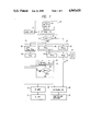
- FIG. 1 is a block diagram of a camera system
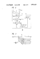
- FIG. 2 is a detailed block diagram of light level correcting means 25.
- FIG. 3 is a chart showing corrected light levels of the light level correcting means 25 shown in FIG. 2;
- FIGS. 4 and 5 illustrate a second embodiment of the present invention, in which:
- FIG. 4 is a detailed block diagram of the light level correcting means 25, and
- FIG. 5 is a chart showing corrected light levels of the light level correcting means 25 shown in FIG. 4;
- FIG. 6 is a view of a single-lens reflex camera in which the present invention is applied.
- FIG. 7 is a chart showing zones for exposure determination with five zones.
- FIG. 8 is a chart showing zones for determining the amount of light emission from the flashing apparatus.
- FIG. 6 illustrates a single-lens reflex camera embodying the present invention, where a photographing lens 2 and a flashing apparatus 27 are mounted on a camera body 1.
- a light flux (constant illumination in this case) passing through the photographing lens 2 is reflected by a mirror 5, then guided through a focusing screen 6 and a pentagonal roof prism 7 and is partly introduced to an eyepiece lens 8, while the remainder is introduced to a light metering system composed of a condenser lens 9 and a photosensor 10.
- the light-receiving area 10a of said photosensor 10 is divided into 5 areas, as shown in FIG. 1, for enabling light metering in the central area and peripheral areas in the object field.
- the function of the camera In the photographing operation, the mirror 5 is lifted, and a diaphragm 4 is reduced to a predetermined aperture. Then a shutter 11 is opened to give an exposure to a photographic film 12, and the flashing apparatus 27 starts light emission. The emitted light is reflected by the principal object. The reflected light, together with the constant illumination (background light), is transmitted by the photographing lens 2 and falls on the film 12 for exposing, and a component reflected by said film 12 enters a photosensor 13 for TTL light control. The output of said photosensor 13 enters a light control circuit, which terminates the light emission from the flashing apparatus 27, upon detection that a predetermined amount of reflected light has entered the photosensor 13.
- FIG. 1 is a block diagram of the system of the present invention.
- Light metering means 20 is composed of photosensor 10 and a light metering circuit 31, which logarithmically compresses the output (photocurrent) of said photosensor 10 and calculates the luminosity by correcting said output with lens data 30 (for example full-open F-number of the photographing lens 2) provided in said lens 2.
- lens data 30 for example full-open F-number of the photographing lens 2
- Flash discrimination means 32 receives a signal, indicating whether or not the flash apparatus 27 (FIG. 6) is used, from automatic or manual setting means (not shown), and sends the outputs of the light metering means 20 (luminosity values of five areas) to exposure calculating means 21 etc. to be explained in the following.
- the outputs of the light metering means 20 are supplied to second exposure calculating means 33 of the exposure calculating means 21, for calculating an appropriate luminance BV ME2 .
- This calculation can be made for example by an algorithm for 5-zone multi-pattern light metering to be explained later in relation to FIG. 7.
- the appropriate luminance BV ME2 is supplied to second control value calculating means 38 of control value calculating means 22, for determining a control luminance value BV CT2 based on the film sensitivity Sv, shutter speed Tv, diaphragm aperture Av, etc.
- the appropriate luminance value BV ME2 is determined by the outputs of the 5-divided photosensor, and indicates a luminance required for obtaining an appropriate exposure.
- the control luminance BV CT2 is determined from the actually controllable shutter speed and diaphragm aperture and the sensitivity of the actually loaded film, and may therefore be different from the appropriate luminance BV ME2 .
- the actually controlled diaphragm aperture will be f22 if the shutter speed is selected at 1/30 sec. though the appropriate aperture for obtaining the appropriate luminance BV ME2 is f32.
- the luminance obtained from the actual shutter speed, diaphragm aperture and film sensitivity corresponds to the control luminance BV CT2 .
- exposure control means 28 activates exposure means 29 composed of the shutter and the diaphragm according to the control luminance BV CT2 , thus completing the exposure operation.
- the outputs of the light metering means 20 are supplied to exposure calculating means 21 and light level determining means 23.
- First exposure calculating means 34 of the exposure calculating means 21 determines the appropriate luminance BV ME1 for example according to the algorithm described in the aforementioned patent. Since the light metering in the present embodiment is conducted in five areas, there is employed an algorithm shown in FIG. 7
- FIG. 7 is a chart for determining the exposure, indicating the maximum luminance difference (maximum luminance B max -minimum luminance B min ) in the ordinate as a function of the average luminance A ve in the abscissa, and the entire chart is divided into four zones BM(*), BHM(*), (2H 1 +H 2 +1)/3 (*) and BM(*).
- a 6 BV5
- a 8 BV9
- a 9 BV11.
- the exposure is determined according to one of the four zones in the chart, to which the outputs of the 5-divided photosensor correspond.
- the first exposure calculating means 34 determines the appropriate luminance BV ME1 according to the above-explained algorithm.
- the first control value calculating means 37 of control value calculating means 22 calculates the control luminance BV CT1 according to the appropriate luminance BV ME1 .
- the appropriate exposure discrimination means 24 receives the aforementioned appropriate luminance BV ME1 and control luminance BV CT1 , and subtraction means 39 calculates the difference ⁇ BV (BV ME1 -BV CT1 ) and sends it to discrimination means 40.
- Light control level determining means 23 calculates the average A ve and the maximum luminance difference B max -B min from five outputs of the light metering means 20, and determines from these values, the light level shift ⁇ TTL (amount of shift from the standard exposure), for example according to an algorithm described in the aforementioned patent. As the light metering in the present embodiment is made in five areas there is employed an algorithm as shown in FIG. 8.
- the light control level is determined in five zones (X 1 -X 5 ).
- the meaning of the chart shown in FIG. 8 is for example as follows:
- the shift ⁇ TTL corrected in the correcting means 25 is supplied to light control means 26 for controlling the light emission from the flashing apparatus 27.
- FIG. 2 is a block diagram of correcting means 25, while FIG. 3 is a chart showing the correction values of the light control level by correcting means 25.
- the discrimination means 40 (FIG. 1) provides a result ⁇ BV ⁇ 0 indicating that the constant illumination (background illumination) is adequately controlled
- a port B is selected.
- setting means 52 sends the light control level shift ⁇ TTL to the light control means 26 without any correction.
- the discrimination means 40 identifies a condition ⁇ BV>0 indicating that the constant illumination (background illumination) provides an over-exposure
- the setting means 52 sends the light control level shift ⁇ TTL to the light control means 26 without any correction.
- the discrimination means 40 identifies a condition ⁇ BV ⁇ 0 indicating that the constant illumination (background illumination) provides an under-exposure, a port A is selected.
- the setting means 55 sets the shift ⁇ TTL at zero and sends it to the light control means 26.
- the flashing apparatus 27 if a difference ⁇ BV is generated between the appropriate luminance BV ME1 and the control luminance BV CT1 to provide an under-exposure for the constant illumination (background illumination) and if the difference ⁇ BV does not exceed 1 EV, namely if within a range 0 ⁇ BV ⁇ -1 shown in FIG. 3, the amount of light emitted from the flashing apparatus 27 is corrected to a higher side according to the above-explained equation, thereby preventing the under-exposure of the principal object.
- the constant illumination background illumination
- the amount of the over-exposure ⁇ BV is in excess of 0 EV, namely in case of a range ⁇ BV ⁇ 0 shown in FIG. 3
- the amount of light emission from the flashing apparatus 27 is controlled according to the algorithm shown in FIG. 8 thereby providing an appropriate exposure for the principal object.
- FIGS. 4 and 5 show a second embodiment of the light control level correcting means, wherein FIG. 4 is a block diagram of said correcting means 25, and FIG. 5 is a chart showing the correction values of the light control levels of correcting means 25.
- the setting means 63 sets the shift ⁇ TTL at zero and sends this value to the light control means 26.
- the second embodiment is simpler than the first embodiment, but can still provide the same effects as in the first embodiment.
Landscapes
- Physics & Mathematics (AREA)
- General Physics & Mathematics (AREA)
- Exposure Control For Cameras (AREA)
- Stroboscope Apparatuses (AREA)
Applications Claiming Priority (2)
| Application Number | Priority Date | Filing Date | Title |
|---|---|---|---|
| JP88116723A JPH01285925A (ja) | 1988-05-13 | 1988-05-13 | カメラ |
| JP63-116723 | 1988-09-05 |
Publications (1)
| Publication Number | Publication Date |
|---|---|
| US4965620A true US4965620A (en) | 1990-10-23 |
Family
ID=14694211
Family Applications (1)
| Application Number | Title | Priority Date | Filing Date |
|---|---|---|---|
| US07/349,846 Expired - Lifetime US4965620A (en) | 1988-05-13 | 1989-05-10 | Camera |
Country Status (2)
| Country | Link |
|---|---|
| US (1) | US4965620A (ja) |
| JP (1) | JPH01285925A (ja) |
Cited By (9)
| Publication number | Priority date | Publication date | Assignee | Title |
|---|---|---|---|---|
| US5172157A (en) * | 1990-11-17 | 1992-12-15 | Nikon Corporation | Automatic light adjustment device for cameras |
| EP0519499A1 (en) * | 1991-06-20 | 1992-12-23 | Nikon Corporation | Automatic flash amount control apparatus of camera |
| US5231447A (en) * | 1991-06-20 | 1993-07-27 | Nikon Corporation | Automatic light adjustment camera and exchangable lenses therefor |
| US5268730A (en) * | 1990-03-19 | 1993-12-07 | Nikon Corporation | Automatic light modulating camera |
| US5504553A (en) * | 1991-06-20 | 1996-04-02 | Nikon Corporation | Automatic light adjustment apparatus for a camera on which a photographic lens can be freely mounted |
| US5576800A (en) * | 1991-11-21 | 1996-11-19 | Nikon Corporation | Camera having an auxiliary photographing function |
| US5576798A (en) * | 1990-11-17 | 1996-11-19 | Nikon Corporation | Automatic flash amount control apparatus of camera |
| US6035135A (en) * | 1997-08-21 | 2000-03-07 | Canon Kabushiki Kaisha | Control of flash device included in or connected to image sensing device |
| US20060268324A1 (en) * | 2005-05-27 | 2006-11-30 | Lite-On Semiconductor Corp. | Multi-function printer |
Families Citing this family (2)
| Publication number | Priority date | Publication date | Assignee | Title |
|---|---|---|---|---|
| EP0464602B1 (en) * | 1990-06-26 | 1997-09-24 | Nikon Corporation | Automatic flash light quantity limiting apparatus for a camera |
| US5442417A (en) * | 1992-07-22 | 1995-08-15 | Nikon Corporation | Automatic flash amount control apparatus of camera |
Citations (2)
| Publication number | Priority date | Publication date | Assignee | Title |
|---|---|---|---|---|
| US4589756A (en) * | 1983-09-20 | 1986-05-20 | Nippon Kogaku K. K. | Method and apparatus for the automatic control of exposure in camera |
| US4809030A (en) * | 1986-09-24 | 1989-02-28 | Nikon Corporation | Camera |
Family Cites Families (1)
| Publication number | Priority date | Publication date | Assignee | Title |
|---|---|---|---|---|
| JPS62174729A (ja) * | 1985-10-16 | 1987-07-31 | Minolta Camera Co Ltd | フラツシユ撮影装置 |
-
1988
- 1988-05-13 JP JP88116723A patent/JPH01285925A/ja active Pending
-
1989
- 1989-05-10 US US07/349,846 patent/US4965620A/en not_active Expired - Lifetime
Patent Citations (2)
| Publication number | Priority date | Publication date | Assignee | Title |
|---|---|---|---|---|
| US4589756A (en) * | 1983-09-20 | 1986-05-20 | Nippon Kogaku K. K. | Method and apparatus for the automatic control of exposure in camera |
| US4809030A (en) * | 1986-09-24 | 1989-02-28 | Nikon Corporation | Camera |
Cited By (13)
| Publication number | Priority date | Publication date | Assignee | Title |
|---|---|---|---|---|
| EP0675387A2 (en) | 1990-03-19 | 1995-10-04 | Nikon Corporation | Automatic light modulating camera |
| US5268730A (en) * | 1990-03-19 | 1993-12-07 | Nikon Corporation | Automatic light modulating camera |
| EP0675388A2 (en) | 1990-03-19 | 1995-10-04 | Nikon Corporation | Automatic light modulating camera |
| EP0675389A2 (en) | 1990-03-19 | 1995-10-04 | Nikon Corporation | Automatic light modulating camera |
| USRE35877E (en) * | 1990-03-19 | 1998-08-25 | Nikon Corporation | Automatic light modulating camera |
| US5172157A (en) * | 1990-11-17 | 1992-12-15 | Nikon Corporation | Automatic light adjustment device for cameras |
| US5576798A (en) * | 1990-11-17 | 1996-11-19 | Nikon Corporation | Automatic flash amount control apparatus of camera |
| EP0519499A1 (en) * | 1991-06-20 | 1992-12-23 | Nikon Corporation | Automatic flash amount control apparatus of camera |
| US5231447A (en) * | 1991-06-20 | 1993-07-27 | Nikon Corporation | Automatic light adjustment camera and exchangable lenses therefor |
| US5504553A (en) * | 1991-06-20 | 1996-04-02 | Nikon Corporation | Automatic light adjustment apparatus for a camera on which a photographic lens can be freely mounted |
| US5576800A (en) * | 1991-11-21 | 1996-11-19 | Nikon Corporation | Camera having an auxiliary photographing function |
| US6035135A (en) * | 1997-08-21 | 2000-03-07 | Canon Kabushiki Kaisha | Control of flash device included in or connected to image sensing device |
| US20060268324A1 (en) * | 2005-05-27 | 2006-11-30 | Lite-On Semiconductor Corp. | Multi-function printer |
Also Published As
| Publication number | Publication date |
|---|---|
| JPH01285925A (ja) | 1989-11-16 |
Similar Documents
| Publication | Publication Date | Title |
|---|---|---|
| US4705382A (en) | Flash photographing apparatus | |
| US5006879A (en) | Electronic flash lighting device for camera | |
| US4965620A (en) | Camera | |
| USRE35877E (en) | Automatic light modulating camera | |
| JPH01280737A (ja) | カメラ | |
| US4984006A (en) | Brightness measuring apparatus for providing adequate object brightness and a flashlight emission apparatus providing adequate exposure, irrespective of photographing conditions | |
| US5218397A (en) | Automatic exposure control apparatus for a camera | |
| US4809030A (en) | Camera | |
| US5023649A (en) | Exposure controlling apparatus of a camera having a plurality of areas for measuring brightness | |
| JP3627111B2 (ja) | ストロボ内蔵カメラ | |
| US4769666A (en) | Apparatus for determining amount of flash | |
| JP2001091988A (ja) | 閃光制御装置 | |
| JPH04371935A (ja) | カメラの自動調光装置 | |
| US4905035A (en) | Camera | |
| JP3021528B2 (ja) | 自動調光カメラ | |
| JPH095611A (ja) | 測距装置 | |
| JPH03269420A (ja) | 自動調光カメラ | |
| JP2884691B2 (ja) | Ttl自動調光カメラ | |
| JPH03287241A (ja) | Ttl自動調光カメラ | |
| JP3124091B2 (ja) | ストロボ露出制御装置を有するカメラ | |
| JP3177942B2 (ja) | ストロボ内蔵カメラ | |
| JP3021527B2 (ja) | Ttl自動調光カメラ | |
| JPH04182631A (ja) | カメラの自動調光装置 | |
| JP2864566B2 (ja) | Ttl自動調光カメラ | |
| JPS6383713A (ja) | カメラの自動日中シンクロシステム |
Legal Events
| Date | Code | Title | Description |
|---|---|---|---|
| AS | Assignment |
Owner name: NIKON CORPORATION, A CORP. OF JAPAN, JAPAN Free format text: ASSIGNMENT OF ASSIGNORS INTEREST.;ASSIGNORS:TAKAGI, TADAO;SATO, TOSHIHIRO;SAEGUSA, TAKASHI;REEL/FRAME:005078/0679 Effective date: 19890508 |
|
| STCF | Information on status: patent grant |
Free format text: PATENTED CASE |
|
| FEPP | Fee payment procedure |
Free format text: PAYOR NUMBER ASSIGNED (ORIGINAL EVENT CODE: ASPN); ENTITY STATUS OF PATENT OWNER: LARGE ENTITY |
|
| FPAY | Fee payment |
Year of fee payment: 4 |
|
| FPAY | Fee payment |
Year of fee payment: 8 |
|
| FPAY | Fee payment |
Year of fee payment: 12 |