US4956734A - Mode changeover mechanism for tape recorders - Google Patents
Mode changeover mechanism for tape recorders Download PDFInfo
- Publication number
- US4956734A US4956734A US07/368,816 US36881689A US4956734A US 4956734 A US4956734 A US 4956734A US 36881689 A US36881689 A US 36881689A US 4956734 A US4956734 A US 4956734A
- Authority
- US
- United States
- Prior art keywords
- gear
- assist
- capstan
- arm
- head plate
- Prior art date
- Legal status (The legal status is an assumption and is not a legal conclusion. Google has not performed a legal analysis and makes no representation as to the accuracy of the status listed.)
- Expired - Fee Related
Links
- 230000007246 mechanism Effects 0.000 title claims abstract description 21
- 238000006243 chemical reaction Methods 0.000 description 4
- 230000007423 decrease Effects 0.000 description 2
- 230000000977 initiatory effect Effects 0.000 description 1
- 238000012986 modification Methods 0.000 description 1
- 230000004048 modification Effects 0.000 description 1
- 230000002093 peripheral effect Effects 0.000 description 1
- 230000009467 reduction Effects 0.000 description 1
- 239000011347 resin Substances 0.000 description 1
- 229920005989 resin Polymers 0.000 description 1
- 230000002194 synthesizing effect Effects 0.000 description 1
- 238000004804 winding Methods 0.000 description 1
Images


Classifications
-
- G—PHYSICS
- G11—INFORMATION STORAGE
- G11B—INFORMATION STORAGE BASED ON RELATIVE MOVEMENT BETWEEN RECORD CARRIER AND TRANSDUCER
- G11B15/00—Driving, starting or stopping record carriers of filamentary or web form; Driving both such record carriers and heads; Guiding such record carriers or containers therefor; Control thereof; Control of operating function
- G11B15/18—Driving; Starting; Stopping; Arrangements for control or regulation thereof
- G11B15/1883—Driving; Starting; Stopping; Arrangements for control or regulation thereof for record carriers inside containers
-
- G—PHYSICS
- G11—INFORMATION STORAGE
- G11B—INFORMATION STORAGE BASED ON RELATIVE MOVEMENT BETWEEN RECORD CARRIER AND TRANSDUCER
- G11B15/00—Driving, starting or stopping record carriers of filamentary or web form; Driving both such record carriers and heads; Guiding such record carriers or containers therefor; Control thereof; Control of operating function
- G11B15/18—Driving; Starting; Stopping; Arrangements for control or regulation thereof
- G11B15/44—Speed-changing arrangements; Reversing arrangements; Drive transfer means therefor
- G11B15/442—Control thereof
Definitions
- tape recorders used for telephone message recorders have been designed such that the "record/playback”, “rewind”, “fast forward” and “stop” modes are remote-controllable.
- an object of the present invention is to provide a mode changeover mechanism for tape recorders, in which a sliding forward movement of a head plate and a change of "playback" and “fast forward” positions are achievable with eccentric and changeover cams of an assist gear without recourse to any solenoid, which makes contribution to current and space savings and reductions in cost, and which can be used in any free position.
- FIG. 2 is a plan view of that mode changeover mechanism
- FIG. 4 is a plan view of part of the mode changeover mechanism for tape recorders in the "stop” and “rewinding" modes
- FIG. 7 is an enlarged view of a gear arm and an assist gear shown in FIG. 6, and
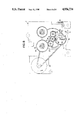
- FIG. 8 is a plan view of the mode changeover mechanism for tape recorders, as viewed through a base plate in the "fast forward" mode.
- the head plate 2 is designed to return to a "stop" position, as shown in FIG. 3, by a spring 14 held by a spring supporter 1a and a spring retainer 1b.
- bent pieces 5a and 5a which are inserted into window openings (not shown) in the base plate 1 to limit the range of rotation thereof. Additionally, a protrusion 5b is provided on one side of the center of the gear arm 5.
- the base plate 1 is fixedly provided with a downward shaft 31 for rotatably supporting the assist gear 4, which is located in a position where it can mesh with the capstan gear 26.
- the assist gear 4 is provided on its outer periphery with toothless segments 4c and 4d, which are in turn provided with triggering engagement means 4e and 4f, defined by pins, to be pushed with the protrusion 5b of the gear arm 5.
- the head plate 2 is provided thereon with a recording/reproducing head 32 and an erasing head 33.
- the gear arm 5 is integrally turned in the clockwise direction so that the gear 27 in constant mesh with the capstan gear 26 meshes with the take-up reel gear 21, since a load is applied to between the gear arm 5 and the capstan gear 26 through the friction mechanism provided for the combination of gear 27 with shaft 29.
- one toothless segment 4d of the assist gear 4 is then located in a position opposite to the capstan gear 26, as illustrated in FIGS. 6 and 7.
- the triggering engagement pin 4f is pushed by the protrusion 5b to cause the assist gear 4 to rotate in the counterclockwise direction. This in turn permits the assist gear 4 to mesh with the capstan gear 26, which then makes a half turn.
- the pin shaft 10 is moved along an inner cam surface 4g of the eccentric cam 4 toward its center to turn the assist arm 4.
- the spring 16 permits the assist arm 3 to be abutted against the bend 2b by the movement of the pin shaft 10, so that when the pin shaft 10 is moved forth with a force smaller than that of the spring 16, the head plate 2 is slid forth integrally therewith. If the head plate 2 is further moved forth until the pinch roller 12 contacts the capstan shaft 13 with a tape located therebetween, as illustrated in FIG. 2, then the sliding movement of the head plate 2 is stopped so that the "record/playback" mode is ready to operate.
- the assist gear 4 continues to rotate further to turn only the assist arm 3 around the screw shaft 15, so that its one side 3b is spaced from the bend 2b and the pin shaft 10 passes through the innermost portion of the eccentric cam 4. Thereafter, upon the other toothless segment 4c of the assist gear 4 reaching the position of the capstan gear 26, the capstan gear 26 disengages the assist gear 4, the rotation of the assist gear 4 is stopped.
- the pin shaft 10 After the pin shaft 10 has passed through the innermost portion of the eccentric cam 4a, it is locked by the spring 16 in a V-shaped notch in the changeover cam 4b. Since the one side 3b of the assist arm 3 is located in a position where it comes in no contact with said bend 2b, however, the pinch roller 12 is pushed against the capstan shaft 13 by the spring 16, while the tape is fed from within a tape cassette toward the tape take-up reel holder 19 at a constant speed.
- the protrusion 5b of the gear arm 5 is located on the left side of the triggering engagement means 4e.
- the motor 25 is slightly rotated in a direction shown by an arrow R in the "record/playback” mode. This then causes the gear arm 5 to be turned, while the triggering engagement means 4e is pushed by the protrusion 5b of FIG. 5, so that the assist gear 4 is slightly rotated by such triggering means in the clockwise direction. This rotation in turn causes the pin shaft 10 to disengage the changeover cam 4b and take the position of FIG. 8, so that the head plate 2 is restored to the "stop" position.
- the tape is wound up at a high speed, since the head plate 2 takes the same position as the "stop" position. It is here understood that higher revolutions per minute of the motor 25 will result in higher speed-winding of the tape.
- the motor 25 is rotated in the counterclockwise direction shown by the arrow R in the "stop" mode of FIG. 6.
- a conversion from the "rewind” mode to the "stop” mode may be achieved by stopping only the rotation of the motor 25.
- the mode changeover mechanism for tape recorders As constructed above, it is possible to decrease the power to be consumed and, hence, reduce the size and weight of the power source section, thus resulting in decreases in cost, since, without recourse to any solenoid, the head plate 1 is moved back and forth by the triggering means for pushing the triggering engagements 4e and 4f of the assist gear 4 with the protrusion 5b of the gear arm 5, thereby controlling the engagement or disengagement of the pinch roller 12 with or from the capstan shaft 13. Furthermore, since the conversion of operational modes takes only depending upon the direction of rotation of the motor 25, such a variation as occurs with the use of a solenoid is unlikely to be induced in the suction characteristics depending upon the position of the mechanical section to be mounted in place. Thus, design can be made with a high degree of freedom. Noises generated from the mechanical section can also be reduced due to no use of any solenoid.
- the changeover operation can take place so rapidly that the length of waiting time can be reduced, since the "playback" and “fast forward” positions can be changed in the position where the changeover cam 4b is engaged with and locked by the pin shaft 10 and the rewinding of the tape can be merely achieved by the rotation of the motor 25.
- the operation of the above mode changeover mechanism for tape recorders involves a repetition of calling-up ⁇ announcing by a voice synthesizing IC, etc. ⁇ recording of message by the actuation of motor ⁇ calling-off ⁇ stopping of motor followed by waiting.
Landscapes
- Transmission Devices (AREA)
- Gear Transmission (AREA)
Applications Claiming Priority (2)
| Application Number | Priority Date | Filing Date | Title |
|---|---|---|---|
| JP63198046A JP2691193B2 (ja) | 1988-08-10 | 1988-08-10 | テープレコーダの動作切換機構 |
| JP63-198046 | 1988-08-10 |
Publications (1)
| Publication Number | Publication Date |
|---|---|
| US4956734A true US4956734A (en) | 1990-09-11 |
Family
ID=16384633
Family Applications (1)
| Application Number | Title | Priority Date | Filing Date |
|---|---|---|---|
| US07/368,816 Expired - Fee Related US4956734A (en) | 1988-08-10 | 1989-06-20 | Mode changeover mechanism for tape recorders |
Country Status (3)
| Country | Link |
|---|---|
| US (1) | US4956734A (ja) |
| JP (1) | JP2691193B2 (ja) |
| KR (1) | KR930001875B1 (ja) |
Cited By (8)
| Publication number | Priority date | Publication date | Assignee | Title |
|---|---|---|---|---|
| US5214551A (en) * | 1988-10-04 | 1993-05-25 | Kyowa Electric & Chemical Co., Ltd. | Mechanism for positioning a magnetic head and a pinch roller in a tape recorder without reliance on a solenoid |
| US5307221A (en) * | 1989-09-04 | 1994-04-26 | Kabushiki Kaisha Sankyo Seiki Seisakusho | Tape recorder mode switch |
| US5363259A (en) * | 1991-08-07 | 1994-11-08 | Sony Corporation | Tape recorder having a compact reverse function including a limiter gear mechanism and a swing arm |
| EP0667610A2 (de) * | 1994-02-09 | 1995-08-16 | GRUNDIG E.M.V. Elektro-Mechanische Versuchsanstalt Max Grundig GmbH & Co. KG | Elektromechanisch gesteuertes Kassetten-Laufwerk |
| US5452160A (en) * | 1992-09-25 | 1995-09-19 | Tokyo Pigeon Co., Ltd. | Mode switching transmitting mechanism for a tape player |
| US5621587A (en) * | 1991-10-04 | 1997-04-15 | Sony Corporation | Tape drive mechanism having a mode cam operated by reverse rotation of motor |
| US5719728A (en) * | 1995-03-08 | 1998-02-17 | Alps Electric Co., Ltd. | Mode changeover apparatus for a tape player with over-stroke correction mechanism |
| US5969900A (en) * | 1991-10-04 | 1999-10-19 | Sony Corporation | Tape drive unit where reverse rotation of a motor determines travel direction and speed of a tape |
Citations (5)
| Publication number | Priority date | Publication date | Assignee | Title |
|---|---|---|---|---|
| US4674001A (en) * | 1983-03-31 | 1987-06-16 | Clarion Co., Ltd. | Cam driven mode selection mechanism for tape recorder |
| US4757405A (en) * | 1985-07-17 | 1988-07-12 | U.S. Philips Corporation | Magnetic-tape apparatus with full and partial head plate advance |
| US4760479A (en) * | 1984-12-17 | 1988-07-26 | Matsushita Electric Industrial Co., Ltd. | Cassette magnetic recording and reproducing device employing a single reversible motor |
| US4873597A (en) * | 1986-06-23 | 1989-10-10 | Nihon Technical Kabushiki Kaisha | Head plate operating mechanism for cassette tape player |
| US4896234A (en) * | 1987-06-30 | 1990-01-23 | Sony Corporation | Mode-change mechanism for tape recording and/or reproducing apparatus |
Family Cites Families (6)
| Publication number | Priority date | Publication date | Assignee | Title |
|---|---|---|---|---|
| JPS5769550A (en) * | 1980-10-14 | 1982-04-28 | Toshiba Corp | Driving circuit for tape recorder |
| JPS57100646A (en) * | 1981-05-12 | 1982-06-22 | Olympus Optical Co Ltd | Reel driving method of tape recorder |
| JPS57180847U (ja) * | 1981-05-13 | 1982-11-16 | ||
| JPS57180848U (ja) * | 1981-05-13 | 1982-11-16 | ||
| JPS57180849U (ja) * | 1981-05-14 | 1982-11-16 | ||
| JPS57198565A (en) * | 1981-05-30 | 1982-12-06 | Nippon Columbia Co Ltd | Magnetic recording and reproducing device |
-
1988
- 1988-08-10 JP JP63198046A patent/JP2691193B2/ja not_active Expired - Fee Related
-
1989
- 1989-01-10 KR KR1019890000184A patent/KR930001875B1/ko not_active IP Right Cessation
- 1989-06-20 US US07/368,816 patent/US4956734A/en not_active Expired - Fee Related
Patent Citations (5)
| Publication number | Priority date | Publication date | Assignee | Title |
|---|---|---|---|---|
| US4674001A (en) * | 1983-03-31 | 1987-06-16 | Clarion Co., Ltd. | Cam driven mode selection mechanism for tape recorder |
| US4760479A (en) * | 1984-12-17 | 1988-07-26 | Matsushita Electric Industrial Co., Ltd. | Cassette magnetic recording and reproducing device employing a single reversible motor |
| US4757405A (en) * | 1985-07-17 | 1988-07-12 | U.S. Philips Corporation | Magnetic-tape apparatus with full and partial head plate advance |
| US4873597A (en) * | 1986-06-23 | 1989-10-10 | Nihon Technical Kabushiki Kaisha | Head plate operating mechanism for cassette tape player |
| US4896234A (en) * | 1987-06-30 | 1990-01-23 | Sony Corporation | Mode-change mechanism for tape recording and/or reproducing apparatus |
Cited By (11)
| Publication number | Priority date | Publication date | Assignee | Title |
|---|---|---|---|---|
| US5214551A (en) * | 1988-10-04 | 1993-05-25 | Kyowa Electric & Chemical Co., Ltd. | Mechanism for positioning a magnetic head and a pinch roller in a tape recorder without reliance on a solenoid |
| US5307221A (en) * | 1989-09-04 | 1994-04-26 | Kabushiki Kaisha Sankyo Seiki Seisakusho | Tape recorder mode switch |
| US5363259A (en) * | 1991-08-07 | 1994-11-08 | Sony Corporation | Tape recorder having a compact reverse function including a limiter gear mechanism and a swing arm |
| US5621587A (en) * | 1991-10-04 | 1997-04-15 | Sony Corporation | Tape drive mechanism having a mode cam operated by reverse rotation of motor |
| US5969900A (en) * | 1991-10-04 | 1999-10-19 | Sony Corporation | Tape drive unit where reverse rotation of a motor determines travel direction and speed of a tape |
| US6181508B1 (en) * | 1991-10-04 | 2001-01-30 | Sony Corporation | Tape drive unit where reverse rotation of a motor determines travel direction and speed of a tape |
| US5452160A (en) * | 1992-09-25 | 1995-09-19 | Tokyo Pigeon Co., Ltd. | Mode switching transmitting mechanism for a tape player |
| CN1040260C (zh) * | 1992-09-25 | 1998-10-14 | 东京鸽有限公司 | 磁带放音机的工作方式转换传动机构 |
| EP0667610A2 (de) * | 1994-02-09 | 1995-08-16 | GRUNDIG E.M.V. Elektro-Mechanische Versuchsanstalt Max Grundig GmbH & Co. KG | Elektromechanisch gesteuertes Kassetten-Laufwerk |
| EP0667610A3 (de) * | 1994-02-09 | 1997-12-17 | GRUNDIG Aktiengesellschaft | Elektromechanisch gesteuertes Kassetten-Laufwerk |
| US5719728A (en) * | 1995-03-08 | 1998-02-17 | Alps Electric Co., Ltd. | Mode changeover apparatus for a tape player with over-stroke correction mechanism |
Also Published As
| Publication number | Publication date |
|---|---|
| JPH0249249A (ja) | 1990-02-19 |
| KR900003844A (ko) | 1990-03-27 |
| KR930001875B1 (ko) | 1993-03-18 |
| JP2691193B2 (ja) | 1997-12-17 |
Similar Documents
| Publication | Publication Date | Title |
|---|---|---|
| US4956734A (en) | Mode changeover mechanism for tape recorders | |
| US4964589A (en) | Mode changing mechanism for a tape player | |
| KR940002079B1 (ko) | 테이프레코오더의 구동장치 | |
| JP3234849B2 (ja) | テーププレーヤのモード切換装置 | |
| WO1984003789A1 (en) | Magnetic recording and reproducing apparatus | |
| JPS6238783B2 (ja) | ||
| JPS6236772A (ja) | 磁気テ−プ装置 | |
| JPS61187151A (ja) | 磁気テ−プ装置 | |
| JPH0248993Y2 (ja) | ||
| JPH082821Y2 (ja) | テーププレーヤ | |
| EP0345739A2 (en) | Magnetic tape recording and playback apparatus | |
| JP2727338B2 (ja) | テープレコーダの駆動装置 | |
| JPH0430676Y2 (ja) | ||
| JP2557603Y2 (ja) | テープレコーダのモード切換機構 | |
| JP3420813B2 (ja) | ブレーキ装置 | |
| JPH0127141Y2 (ja) | ||
| KR910005800B1 (ko) | 테이프 레코더의 모드 변환 기구 | |
| JPH079213Y2 (ja) | テーププレーヤ | |
| JPH0548269Y2 (ja) | ||
| JP2956415B2 (ja) | 磁気記録再生装置 | |
| JPH0341301Y2 (ja) | ||
| JPH079214Y2 (ja) | テーププレーヤ | |
| JPS6361442A (ja) | テ−プ記録再生装置 | |
| JPH0734504Y2 (ja) | テーププレーヤのモード切換装置 | |
| JPS5823353A (ja) | ビデオテ−プレコ−ダのテ−プロ−デイング |
Legal Events
| Date | Code | Title | Description |
|---|---|---|---|
| AS | Assignment |
Owner name: KABUSHIKI KAISHA SANKYO SEIKI SEISAKUSHO, JAPAN Free format text: ASSIGNMENT OF ASSIGNORS INTEREST.;ASSIGNOR:KAMIJO, MASAO;REEL/FRAME:005095/0186 Effective date: 19890612 Owner name: TOKYO PIGEON CO., LTD., JAPAN Free format text: ASSIGNMENT OF ASSIGNORS INTEREST.;ASSIGNOR:KAMIJO, MASAO;REEL/FRAME:005095/0186 Effective date: 19890612 |
|
| CC | Certificate of correction | ||
| FEPP | Fee payment procedure |
Free format text: PAYOR NUMBER ASSIGNED (ORIGINAL EVENT CODE: ASPN); ENTITY STATUS OF PATENT OWNER: LARGE ENTITY |
|
| FPAY | Fee payment |
Year of fee payment: 4 |
|
| FEPP | Fee payment procedure |
Free format text: PAYER NUMBER DE-ASSIGNED (ORIGINAL EVENT CODE: RMPN); ENTITY STATUS OF PATENT OWNER: LARGE ENTITY Free format text: PAYOR NUMBER ASSIGNED (ORIGINAL EVENT CODE: ASPN); ENTITY STATUS OF PATENT OWNER: LARGE ENTITY |
|
| REMI | Maintenance fee reminder mailed | ||
| LAPS | Lapse for failure to pay maintenance fees | ||
| FP | Lapsed due to failure to pay maintenance fee |
Effective date: 19980911 |
|
| STCH | Information on status: patent discontinuation |
Free format text: PATENT EXPIRED DUE TO NONPAYMENT OF MAINTENANCE FEES UNDER 37 CFR 1.362 |