US4729949A - System and methods for cell selection - Google Patents
System and methods for cell selection Download PDFInfo
- Publication number
- US4729949A US4729949A US06/550,233 US55023383A US4729949A US 4729949 A US4729949 A US 4729949A US 55023383 A US55023383 A US 55023383A US 4729949 A US4729949 A US 4729949A
- Authority
- US
- United States
- Prior art keywords
- carrier
- cells
- cell
- living
- holes
- Prior art date
- Legal status (The legal status is an assumption and is not a legal conclusion. Google has not performed a legal analysis and makes no representation as to the accuracy of the status listed.)
- Expired - Lifetime
Links
- 238000000034 method Methods 0.000 title claims abstract description 94
- 239000012530 fluid Substances 0.000 claims abstract description 31
- 210000004027 cell Anatomy 0.000 claims description 583
- 210000004698 lymphocyte Anatomy 0.000 claims description 62
- 239000000969 carrier Substances 0.000 claims description 60
- 230000003287 optical effect Effects 0.000 claims description 40
- 230000005684 electric field Effects 0.000 claims description 21
- 230000000694 effects Effects 0.000 claims description 18
- 238000005406 washing Methods 0.000 claims description 17
- 239000000126 substance Substances 0.000 claims description 16
- 238000000576 coating method Methods 0.000 claims description 13
- 230000004044 response Effects 0.000 claims description 13
- 239000011248 coating agent Substances 0.000 claims description 12
- 230000002147 killing effect Effects 0.000 claims description 12
- 239000000523 sample Substances 0.000 claims description 10
- VYPSYNLAJGMNEJ-UHFFFAOYSA-N Silicium dioxide Chemical compound O=[Si]=O VYPSYNLAJGMNEJ-UHFFFAOYSA-N 0.000 claims description 9
- 239000004020 conductor Substances 0.000 claims description 9
- 239000011521 glass Substances 0.000 claims description 9
- 229910052751 metal Inorganic materials 0.000 claims description 9
- 239000002184 metal Substances 0.000 claims description 9
- 239000000463 material Substances 0.000 claims description 8
- 150000002500 ions Chemical class 0.000 claims description 5
- 238000005868 electrolysis reaction Methods 0.000 claims description 4
- 239000000377 silicon dioxide Substances 0.000 claims description 4
- 229910007237 Si2 O3 Inorganic materials 0.000 claims description 3
- 229910052681 coesite Inorganic materials 0.000 claims description 2
- 229910052906 cristobalite Inorganic materials 0.000 claims description 2
- 239000000203 mixture Substances 0.000 claims description 2
- 239000000615 nonconductor Substances 0.000 claims description 2
- 229910052682 stishovite Inorganic materials 0.000 claims description 2
- 229910052905 tridymite Inorganic materials 0.000 claims description 2
- 238000012360 testing method Methods 0.000 description 46
- 239000000243 solution Substances 0.000 description 36
- 238000000926 separation method Methods 0.000 description 33
- 210000004369 blood Anatomy 0.000 description 28
- 239000008280 blood Substances 0.000 description 28
- 230000010287 polarization Effects 0.000 description 17
- 230000000638 stimulation Effects 0.000 description 17
- CHADEQDQBURGHL-UHFFFAOYSA-N (6'-acetyloxy-3-oxospiro[2-benzofuran-1,9'-xanthene]-3'-yl) acetate Chemical compound O1C(=O)C2=CC=CC=C2C21C1=CC=C(OC(C)=O)C=C1OC1=CC(OC(=O)C)=CC=C21 CHADEQDQBURGHL-UHFFFAOYSA-N 0.000 description 16
- 238000004458 analytical method Methods 0.000 description 16
- LOKCTEFSRHRXRJ-UHFFFAOYSA-I dipotassium trisodium dihydrogen phosphate hydrogen phosphate dichloride Chemical compound P(=O)(O)(O)[O-].[K+].P(=O)(O)([O-])[O-].[Na+].[Na+].[Cl-].[K+].[Cl-].[Na+] LOKCTEFSRHRXRJ-UHFFFAOYSA-I 0.000 description 13
- 239000002953 phosphate buffered saline Substances 0.000 description 13
- 238000003745 diagnosis Methods 0.000 description 11
- 210000003743 erythrocyte Anatomy 0.000 description 11
- GNBHRKFJIUUOQI-UHFFFAOYSA-N fluorescein Chemical compound O1C(=O)C2=CC=CC=C2C21C1=CC=C(O)C=C1OC1=CC(O)=CC=C21 GNBHRKFJIUUOQI-UHFFFAOYSA-N 0.000 description 11
- 238000001878 scanning electron micrograph Methods 0.000 description 11
- 238000005259 measurement Methods 0.000 description 10
- 230000008569 process Effects 0.000 description 10
- 238000003287 bathing Methods 0.000 description 9
- RYGMFSIKBFXOCR-UHFFFAOYSA-N Copper Chemical compound [Cu] RYGMFSIKBFXOCR-UHFFFAOYSA-N 0.000 description 8
- 229910052802 copper Inorganic materials 0.000 description 8
- 239000010949 copper Substances 0.000 description 8
- XLYOFNOQVPJJNP-UHFFFAOYSA-N water Substances O XLYOFNOQVPJJNP-UHFFFAOYSA-N 0.000 description 8
- 206010028980 Neoplasm Diseases 0.000 description 7
- 229910052710 silicon Inorganic materials 0.000 description 7
- 239000010703 silicon Substances 0.000 description 7
- 239000002269 analeptic agent Substances 0.000 description 6
- 230000008901 benefit Effects 0.000 description 6
- 230000036770 blood supply Effects 0.000 description 6
- 230000008859 change Effects 0.000 description 6
- 230000005284 excitation Effects 0.000 description 6
- 239000007788 liquid Substances 0.000 description 6
- 239000011159 matrix material Substances 0.000 description 6
- 201000011510 cancer Diseases 0.000 description 5
- 210000005069 ears Anatomy 0.000 description 5
- 238000011049 filling Methods 0.000 description 5
- 230000004913 activation Effects 0.000 description 4
- 239000000427 antigen Substances 0.000 description 4
- 102000036639 antigens Human genes 0.000 description 4
- 108091007433 antigens Proteins 0.000 description 4
- 210000000601 blood cell Anatomy 0.000 description 4
- 230000002596 correlated effect Effects 0.000 description 4
- 238000013480 data collection Methods 0.000 description 4
- 208000037265 diseases, disorders, signs and symptoms Diseases 0.000 description 4
- 239000012153 distilled water Substances 0.000 description 4
- 238000002875 fluorescence polarization Methods 0.000 description 4
- 230000006870 function Effects 0.000 description 4
- 108010047620 Phytohemagglutinins Proteins 0.000 description 3
- 230000001133 acceleration Effects 0.000 description 3
- 238000003556 assay Methods 0.000 description 3
- 230000005540 biological transmission Effects 0.000 description 3
- 239000006285 cell suspension Substances 0.000 description 3
- 238000000151 deposition Methods 0.000 description 3
- 230000008021 deposition Effects 0.000 description 3
- 238000010586 diagram Methods 0.000 description 3
- 201000010099 disease Diseases 0.000 description 3
- 238000000295 emission spectrum Methods 0.000 description 3
- 238000005429 filling process Methods 0.000 description 3
- 238000011065 in-situ storage Methods 0.000 description 3
- 230000003993 interaction Effects 0.000 description 3
- 238000011835 investigation Methods 0.000 description 3
- 230000000670 limiting effect Effects 0.000 description 3
- 238000012986 modification Methods 0.000 description 3
- 230000004048 modification Effects 0.000 description 3
- 230000001885 phytohemagglutinin Effects 0.000 description 3
- 230000002441 reversible effect Effects 0.000 description 3
- 235000012239 silicon dioxide Nutrition 0.000 description 3
- 238000005481 NMR spectroscopy Methods 0.000 description 2
- PXHVJJICTQNCMI-UHFFFAOYSA-N Nickel Chemical compound [Ni] PXHVJJICTQNCMI-UHFFFAOYSA-N 0.000 description 2
- 101000794475 Schistosoma mansoni Calcium-binding protein Proteins 0.000 description 2
- QCWXUUIWCKQGHC-UHFFFAOYSA-N Zirconium Chemical compound [Zr] QCWXUUIWCKQGHC-UHFFFAOYSA-N 0.000 description 2
- 238000004364 calculation method Methods 0.000 description 2
- 210000000170 cell membrane Anatomy 0.000 description 2
- 238000006243 chemical reaction Methods 0.000 description 2
- 230000007423 decrease Effects 0.000 description 2
- 238000011068 loading method Methods 0.000 description 2
- 238000004519 manufacturing process Methods 0.000 description 2
- 239000012528 membrane Substances 0.000 description 2
- 239000004033 plastic Substances 0.000 description 2
- 238000012545 processing Methods 0.000 description 2
- 230000004936 stimulating effect Effects 0.000 description 2
- 230000007704 transition Effects 0.000 description 2
- 229910052726 zirconium Inorganic materials 0.000 description 2
- 241000237970 Conus <genus> Species 0.000 description 1
- BQCADISMDOOEFD-UHFFFAOYSA-N Silver Chemical compound [Ag] BQCADISMDOOEFD-UHFFFAOYSA-N 0.000 description 1
- 208000000453 Skin Neoplasms Diseases 0.000 description 1
- 238000010521 absorption reaction Methods 0.000 description 1
- 230000009471 action Effects 0.000 description 1
- 230000003213 activating effect Effects 0.000 description 1
- 239000000853 adhesive Substances 0.000 description 1
- 230000001070 adhesive effect Effects 0.000 description 1
- 238000013459 approach Methods 0.000 description 1
- 230000006399 behavior Effects 0.000 description 1
- 238000004166 bioassay Methods 0.000 description 1
- 230000004071 biological effect Effects 0.000 description 1
- 239000013060 biological fluid Substances 0.000 description 1
- 230000008827 biological function Effects 0.000 description 1
- 238000010170 biological method Methods 0.000 description 1
- 230000015572 biosynthetic process Effects 0.000 description 1
- 230000000903 blocking effect Effects 0.000 description 1
- 230000017531 blood circulation Effects 0.000 description 1
- 238000009529 body temperature measurement Methods 0.000 description 1
- 210000001185 bone marrow Anatomy 0.000 description 1
- 230000001680 brushing effect Effects 0.000 description 1
- 230000009172 bursting Effects 0.000 description 1
- 230000021164 cell adhesion Effects 0.000 description 1
- 230000036755 cellular response Effects 0.000 description 1
- 238000005119 centrifugation Methods 0.000 description 1
- 239000003153 chemical reaction reagent Substances 0.000 description 1
- 239000003795 chemical substances by application Substances 0.000 description 1
- 238000003759 clinical diagnosis Methods 0.000 description 1
- 230000002860 competitive effect Effects 0.000 description 1
- 238000004590 computer program Methods 0.000 description 1
- 239000012141 concentrate Substances 0.000 description 1
- 238000011109 contamination Methods 0.000 description 1
- 230000001276 controlling effect Effects 0.000 description 1
- 125000004122 cyclic group Chemical group 0.000 description 1
- 230000001086 cytosolic effect Effects 0.000 description 1
- 230000003247 decreasing effect Effects 0.000 description 1
- 238000005137 deposition process Methods 0.000 description 1
- 238000013461 design Methods 0.000 description 1
- 238000001514 detection method Methods 0.000 description 1
- 238000011161 development Methods 0.000 description 1
- 230000018109 developmental process Effects 0.000 description 1
- 238000002405 diagnostic procedure Methods 0.000 description 1
- 238000007599 discharging Methods 0.000 description 1
- 208000035475 disorder Diseases 0.000 description 1
- 238000006073 displacement reaction Methods 0.000 description 1
- 230000005672 electromagnetic field Effects 0.000 description 1
- 238000001962 electrophoresis Methods 0.000 description 1
- 230000007613 environmental effect Effects 0.000 description 1
- 238000011156 evaluation Methods 0.000 description 1
- 230000001747 exhibiting effect Effects 0.000 description 1
- 238000002474 experimental method Methods 0.000 description 1
- 239000000284 extract Substances 0.000 description 1
- PCHJSUWPFVWCPO-UHFFFAOYSA-N gold Chemical compound [Au] PCHJSUWPFVWCPO-UHFFFAOYSA-N 0.000 description 1
- 229910052737 gold Inorganic materials 0.000 description 1
- 239000010931 gold Substances 0.000 description 1
- 210000003714 granulocyte Anatomy 0.000 description 1
- 238000007654 immersion Methods 0.000 description 1
- 238000010166 immunofluorescence Methods 0.000 description 1
- 238000010348 incorporation Methods 0.000 description 1
- 238000007373 indentation Methods 0.000 description 1
- 238000009776 industrial production Methods 0.000 description 1
- 238000010849 ion bombardment Methods 0.000 description 1
- 239000000644 isotonic solution Substances 0.000 description 1
- 208000032839 leukemia Diseases 0.000 description 1
- 210000000265 leukocyte Anatomy 0.000 description 1
- 150000002632 lipids Chemical class 0.000 description 1
- 210000001165 lymph node Anatomy 0.000 description 1
- 210000002540 macrophage Anatomy 0.000 description 1
- 230000003211 malignant effect Effects 0.000 description 1
- 230000007246 mechanism Effects 0.000 description 1
- 150000002739 metals Chemical class 0.000 description 1
- 238000001000 micrograph Methods 0.000 description 1
- 239000003226 mitogen Substances 0.000 description 1
- 230000007935 neutral effect Effects 0.000 description 1
- 229910052759 nickel Inorganic materials 0.000 description 1
- 210000000056 organ Anatomy 0.000 description 1
- 238000001259 photo etching Methods 0.000 description 1
- 238000002360 preparation method Methods 0.000 description 1
- 239000010453 quartz Substances 0.000 description 1
- 230000005855 radiation Effects 0.000 description 1
- 238000003127 radioimmunoassay Methods 0.000 description 1
- 230000009467 reduction Effects 0.000 description 1
- 238000011160 research Methods 0.000 description 1
- 238000007789 sealing Methods 0.000 description 1
- 229910052709 silver Inorganic materials 0.000 description 1
- 239000004332 silver Substances 0.000 description 1
- 201000000849 skin cancer Diseases 0.000 description 1
- 239000007787 solid Substances 0.000 description 1
- 230000003595 spectral effect Effects 0.000 description 1
- 238000001228 spectrum Methods 0.000 description 1
- 238000009987 spinning Methods 0.000 description 1
- 238000010972 statistical evaluation Methods 0.000 description 1
- 239000000021 stimulant Substances 0.000 description 1
- 239000000725 suspension Substances 0.000 description 1
- 238000010408 sweeping Methods 0.000 description 1
- 230000003797 telogen phase Effects 0.000 description 1
- 210000001519 tissue Anatomy 0.000 description 1
- 238000012546 transfer Methods 0.000 description 1
- 238000002054 transplantation Methods 0.000 description 1
- 238000007740 vapor deposition Methods 0.000 description 1
- 230000000007 visual effect Effects 0.000 description 1
Images


Classifications
-
- C—CHEMISTRY; METALLURGY
- C12—BIOCHEMISTRY; BEER; SPIRITS; WINE; VINEGAR; MICROBIOLOGY; ENZYMOLOGY; MUTATION OR GENETIC ENGINEERING
- C12M—APPARATUS FOR ENZYMOLOGY OR MICROBIOLOGY; APPARATUS FOR CULTURING MICROORGANISMS FOR PRODUCING BIOMASS, FOR GROWING CELLS OR FOR OBTAINING FERMENTATION OR METABOLIC PRODUCTS, i.e. BIOREACTORS OR FERMENTERS
- C12M3/00—Tissue, human, animal or plant cell, or virus culture apparatus
-
- G—PHYSICS
- G01—MEASURING; TESTING
- G01N—INVESTIGATING OR ANALYSING MATERIALS BY DETERMINING THEIR CHEMICAL OR PHYSICAL PROPERTIES
- G01N15/00—Investigating characteristics of particles; Investigating permeability, pore-volume, or surface-area of porous materials
- G01N15/10—Investigating individual particles
-
- C—CHEMISTRY; METALLURGY
- C12—BIOCHEMISTRY; BEER; SPIRITS; WINE; VINEGAR; MICROBIOLOGY; ENZYMOLOGY; MUTATION OR GENETIC ENGINEERING
- C12M—APPARATUS FOR ENZYMOLOGY OR MICROBIOLOGY; APPARATUS FOR CULTURING MICROORGANISMS FOR PRODUCING BIOMASS, FOR GROWING CELLS OR FOR OBTAINING FERMENTATION OR METABOLIC PRODUCTS, i.e. BIOREACTORS OR FERMENTERS
- C12M23/00—Constructional details, e.g. recesses, hinges
- C12M23/02—Form or structure of the vessel
- C12M23/12—Well or multiwell plates
-
- C—CHEMISTRY; METALLURGY
- C12—BIOCHEMISTRY; BEER; SPIRITS; WINE; VINEGAR; MICROBIOLOGY; ENZYMOLOGY; MUTATION OR GENETIC ENGINEERING
- C12M—APPARATUS FOR ENZYMOLOGY OR MICROBIOLOGY; APPARATUS FOR CULTURING MICROORGANISMS FOR PRODUCING BIOMASS, FOR GROWING CELLS OR FOR OBTAINING FERMENTATION OR METABOLIC PRODUCTS, i.e. BIOREACTORS OR FERMENTERS
- C12M41/00—Means for regulation, monitoring, measurement or control, e.g. flow regulation
- C12M41/46—Means for regulation, monitoring, measurement or control, e.g. flow regulation of cellular or enzymatic activity or functionality, e.g. cell viability
-
- C—CHEMISTRY; METALLURGY
- C12—BIOCHEMISTRY; BEER; SPIRITS; WINE; VINEGAR; MICROBIOLOGY; ENZYMOLOGY; MUTATION OR GENETIC ENGINEERING
- C12M—APPARATUS FOR ENZYMOLOGY OR MICROBIOLOGY; APPARATUS FOR CULTURING MICROORGANISMS FOR PRODUCING BIOMASS, FOR GROWING CELLS OR FOR OBTAINING FERMENTATION OR METABOLIC PRODUCTS, i.e. BIOREACTORS OR FERMENTERS
- C12M47/00—Means for after-treatment of the produced biomass or of the fermentation or metabolic products, e.g. storage of biomass
- C12M47/04—Cell isolation or sorting
-
- B—PERFORMING OPERATIONS; TRANSPORTING
- B01—PHYSICAL OR CHEMICAL PROCESSES OR APPARATUS IN GENERAL
- B01J—CHEMICAL OR PHYSICAL PROCESSES, e.g. CATALYSIS OR COLLOID CHEMISTRY; THEIR RELEVANT APPARATUS
- B01J2219/00—Chemical, physical or physico-chemical processes in general; Their relevant apparatus
- B01J2219/00274—Sequential or parallel reactions; Apparatus and devices for combinatorial chemistry or for making arrays; Chemical library technology
- B01J2219/00277—Apparatus
- B01J2219/00279—Features relating to reactor vessels
- B01J2219/00306—Reactor vessels in a multiple arrangement
- B01J2219/00313—Reactor vessels in a multiple arrangement the reactor vessels being formed by arrays of wells in blocks
- B01J2219/00315—Microtiter plates
- B01J2219/00317—Microwell devices, i.e. having large numbers of wells
-
- C—CHEMISTRY; METALLURGY
- C40—COMBINATORIAL TECHNOLOGY
- C40B—COMBINATORIAL CHEMISTRY; LIBRARIES, e.g. CHEMICAL LIBRARIES
- C40B60/00—Apparatus specially adapted for use in combinatorial chemistry or with libraries
- C40B60/14—Apparatus specially adapted for use in combinatorial chemistry or with libraries for creating libraries
-
- Y—GENERAL TAGGING OF NEW TECHNOLOGICAL DEVELOPMENTS; GENERAL TAGGING OF CROSS-SECTIONAL TECHNOLOGIES SPANNING OVER SEVERAL SECTIONS OF THE IPC; TECHNICAL SUBJECTS COVERED BY FORMER USPC CROSS-REFERENCE ART COLLECTIONS [XRACs] AND DIGESTS
- Y10—TECHNICAL SUBJECTS COVERED BY FORMER USPC
- Y10T—TECHNICAL SUBJECTS COVERED BY FORMER US CLASSIFICATION
- Y10T436/00—Chemistry: analytical and immunological testing
- Y10T436/25—Chemistry: analytical and immunological testing including sample preparation
- Y10T436/25375—Liberation or purification of sample or separation of material from a sample [e.g., filtering, centrifuging, etc.]
Definitions
- the present invention refers to equipment and methods for cell selection and, more particularly, to such equipment and methods for trapping individual cells at known locations thereby for use among other ways in selecting at least one sub-population of cells, using defined parameters common to its members, from a more general cell population. More generally, the invention relates to equipment and methods for simultaneously studying large groups of living cells, e.g., 10,000 or more individual cells, on a cell-by-cell basis.
- This method is not very efficient and is not suitable for separation of different cells which have the same membrane characteristics, e.g., between cells that stick to glass.
- This method is based on known binding characteristics of sub-populations of cells to certain antigens and/or antibodies. The selective binding of these particular types of cells allows sub-populations of cells to be identified.
- This method achieves cell-separation based on the relative rates of movement of different types of cells in an electric field. Thus, the method cannot be used to separate different groups of cells which respond to an electric field in the same manner.
- Radio assay including radio immunoassay, radio incorporation assay, radio enzymological assay
- Distinction between cells is based on their physical appearance. This method is quick but the coarsest of all.
- cells float upon an isotonic solution of known density, osomolarity and viscosity.
- This configuration is subjected to acceleration forces by centrifugation at a given temperature and acceleration.
- the cells having a specific weight greater than that of the solution sink.
- Those having the specific density of the solution are suspended in it, and those with a specific density less than that of the solution float above it.
- the main problem with this method is the cells' compartmentalization within the density gradient, which is influenced by ambient conditions such as temperature, osmolality, acceleration, e.g., the distance of the interface between the blood and the gradient from the spinning axis.
- Each of the selected cells, separated from one another, is at a precise known location. All the selected cells are subjectable to common tests, yet the effect on each individual cell is determinable, thereby enabling more accurate diagnosis.
- the tests and the effects on each cell are performed automatically in order to reduce the testing time and to permit the task to be performed by relatively unskilled personnel.
- the inventive method may include one or more of the following steps:
- the novel equipment includes a cell carrier which has an array of cell receiving holes, where for each hole, the location in the array, or address, is fixed and known.
- the holes extend from the carrier top side to a spaced apart bottom side.
- the holes have preselected configurations so that when a batch of cells passes over the carrier top side only preselected cells, based on their particular size, enter and become supported in the holes. Cells of sizes smaller than those of the selected cells pass through the holes, while much larger cells cannot enter the holes.
- the cells in the carrier holes are then subjectable to biological tests and particular properties thereof are measured on a cell-by-cell basis, to determine which of the cells belong to a particular subgroup, based on their particular properties and their measured parameters.
- a subgroup of cells has been identified, since each cell thereof is at a known address, the addresses of all the subgroup cells are known.
- FIGS. 1A-1E are schematic illustrations, partly in sectional view, of preferred cell carriers of the invention.
- FIGS. 2A-2D illustrate one embodiment of a multiple cell carrier holder for carrying out measuring cycles at a plurality of cell carriers.
- FIGS. 3A and 3B are enlarged sectional views of the holder of FIG. 2.
- FIG. 4 schematically exhibits an optical analyzer for scanning individually the cells of the population contained in a cell carrier.
- FIG. 5 schematically shows a second embodiment of an optical analyzer.
- FIGS. 6A-6C exhibit modified holders of the embodiment of FIG. 3.
- FIGS. 7A and 7B show an embodiment of a flow chamber for a bottom side analyzing system.
- FIG. 8 is a modified version of the flow chamber of FIG. 7.
- FIG. 9 is again another embodiment of a holder and a flow chamber for an advanced analyzing system.
- FIG. 10 is a separation unit adapted to receive the holder of FIG. 6 for providing the cell carriers with cells.
- FIG. 11 is a sectional view of parts of the embodiment shown in FIG. 10.
- FIGS. 12A and 12B exhibit a separation unit adapted to receive the holder of FIG. 9 for providing the cell carriers with cells.
- FIGS. 13A-13C are details of a blood supply element adapted for use with the separation unit of FIG. 12.
- FIG. 14 is a sectional view of another embodiment of a blood supply element adapted for use with the separation unit of FIG. 12.
- FIGS. 15A and 15B show an embodiment of a multi-carrier system for clinical use, wherein the separation and the measuring steps are combined.
- FIG. 16 is a schematic overall illustration of an optical diagnosis system according to the invention.
- FIG. 17 illustrates a cell carrier for selectively attracting or releasing desired cells.
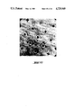
- FIGS. 18-20 are scanning electron micrographs of copper carriers for use with the present invention.
- FIG. 21 is a scanning electron micrograph showing a copper carrier coated with silicon.
- FIG. 22 is a scanning electron micrograph showing a copper carrier having square-shaped apertures which are sized to hold and retain lymphocytes having a cross-sectional size of approximately 7 ⁇ m.
- FIG. 23 shows a typical experimental arrangement suitable for loading cells into carriers of the types shown in FIGS. 18-22.
- FIGS. 24-26 illustrate the process of filling a carrier with cells.
- FIGS. 27-28 are scanning electron micrographs showing a carrier filled with lymphocytes.
- FIGS. 29-32 are scanning electron micrographs showing individual cells in individual apertures of a carrier.
- FIGS. 33-34 illustrate the process of washing the carrier to remove excess cells and debris.
- FIGS. 35-36 are scanning electron micrographs showing the surface of the carrier prior to washing.
- FIGS. 37-41 are a sequence of still photographs of a videotape showing that the cells are not permanently bound to the carrier.
- FIGS. 42-46 are a sequence of still photographs of a videotape demonstrating that substances can be applied (FIGS. 42-44) and removed (FIGS. 45-46) from cells held in the apertures of a carrier.
- FIG. 47 shows the use of an electric field to drive cells into the apertures of a carrier.
- FIG. 48 shows the use of crossed electric and magnet fields to drive cells into the apertures of a carrier.
- FIGS. 49-50 show the use of a time varying magnetic field to enhance fluid exchange about cells captured in a carrier.
- FIG. 51 shows the use of a time varying E field crossed with a constant B field to select a sub-population of cells captured in a carrier based on their charge to mass ratio.
- FIG. 52 is a circuit for receiving and processing input data from the photomultiplier tubes of FIG. 4.
- FIG. 53 is a flow diagram of a routine for scanning a carrier to identify cells having fluorescence polarization control values within a desired range.
- the invention will first be described, in a non-limiting way, with regard to selecting and analyzing a particular population of cells of a given type contained in a biological fluid from other populations of cells.
- a further selection of a special sub-population can be separated from the particular population selected.
- the invention will first be described in connection with selecting and analyzing a particular sub-population of lymphocytes, which are present in human blood, by first separating the lymphocytes from other types of cells, and then testing the lymphocytes to identify a sub-population or subgroup within the group of lymphocytes.
- the present invention makes it possible to realize such analyses very quickly, and accurately. In this particular case, both speed and accuracy are very important, considering the potential number of cancer diagnosis tests that one may wish to perform. Equally important, the novel invention, both in terms of the system and method, provides capabilities for separating biological cells from one another by placing each separated cell at a known address, to which one can return, for repeated cell observation and/or repeated stimulations followed by subsequent analysis.
- a large number of cells e.g., lymphocytes in the blood, which can be thought of as representing a group or population of cells, are first separated from all other cells, i.e., from different groups of populations of cells.
- the separated lymphocytes are subjected simultaneously to selected tests and thereafter each cell is separately investigated to determine whether or not, as a result of the test, or stimulation, it exhibits a particular property.
- the address of every cell exhibiting said property is recorded.
- the addresses of all the cells which exhibited the particular property are known.
- the cells in the subgroup may be subjected to one or more additional tests.
- additional tests as to investigating the properties of the cells as a result of these additional test(s) it can be limited to only the cells in the subgroup.
- Each cell in the subgroup is individually investigated by directing the investigative instrumentation to the cell's unique known location or address.
- all other cells, though belonging to the same group, but not being part of the subgroup are ignored in that they are not subjected to any investigation. Consequently once the subgroup has been identified only its cells are investigated, thereby limiting investigation time only to the subgroup cells which are of interest.
- the investigation is done on a cell-by-cell basis, more precise data is obtainable for increased diagnosis accuracy.
- Other advantages of being able to identify cells of a subgroup and investigate each one individually will be discussed hereinafter.
- the lymphocytes are separated from the other cells contained in the blood.
- the separation is performed by means of a perforated cell carrier 1 as shown in FIG. 1A.
- the carrier includes base 3 in which are formed apertures or holes 2.
- the cell carrier 1 may have various configurations of apertures of holes 2, as well as the manner in which they are arranged.
- FIG. 1A they are assumed to be arranged in rows and columns along axes X and Y, respectively.
- the holes are shown as having larger openings at the tops than at the bottoms thereof, as shown in FIG. 1B.
- the side walls of the apertures may converge continuously or in steps, as shown in FIG. 1C, towards the opening at the bottom side 1b of the cell carrier. Also, as shown in FIG.
- the shape of the apertures 2 enables the cells to be effectively held to the carrier by applying means, such as a pressure difference between the upper and the bottom side of the carrier, or electromagnetic forces.
- the carrier 1 is chosen to have holes of sizes so that when the matter, e.g., blood, containing the various cell groups is placed on the carrier 1, effectively most if not all of the holes are occupied by cells of the group of interest, one cell per hole.
- the holes are sized to be suited for receiving lymphocytes, among which there are two main sizes of about 7 ⁇ m and about 10-15 ⁇ m, the 7 ⁇ m lymphocytes being the cells of interest.
- the apertures should have a cross-sectional dimension of approximately 10 ⁇ m and that at the bottom surface or side 1b, they should have a cross-sectional dimension of approximately 5 ⁇ m. In this way, the desired population of cells can easily enter the aperture without suffering substantial damage and yet, once in the aperture, the cells cannot pass out of the bottom of the carrier.
- the aperture should be shaped so that either at its bottom side or at a cross-section intermediate sides 1t and 1b the cross-sectional dimension is less than at the top side, so that a desired cell entering an aperture does not pass through the aperture, but rather is held therein.
- FIG. 1E illustrates an aperture configuration wherein the minimum cross-section is located in a plane intermediate between the top and bottom sides of the carrier.
- the carrier thickness between the top and the level of the minimum cross-sectional dimension so that the size of the aperture is related to the size of the desired cells so that when a desired cell enters an aperture practically the entire cell is within the aperture, thus preventing it from being washed out during a washing step, as will be described.
- the carrier 1 is made of any appropriate matter, e.g., metals such as copper, gold, nickel, silver or others, or of plastic, which may be provided with electrically conducting portions, extending between the holes 2 as shown in FIG. 17.
- electrically conducting portions extending between the holes 2 as shown in FIG. 17.
- Suitable coating materials include silicon, silicon dioxide and various inorganic glasses.
- silicon, silicon dioxide and various inorganic glasses When using such coating materials, or for that matter, when choosing a material from which to make an uncoated carrier, it is important to determine that the material does not interact with the cells in a way which will interfere with the test or tests to be performed.
- FIGS. 18, 19 and 20 Scanning electron micrographs of a copper carrier for use with the present invention are shown in FIGS. 18, 19 and 20.
- FIG. 18 shows the top surface of the carrier at a magnification of 1000 ⁇ .
- the apertures have a cross-sectional dimension (diameter) of approximately 11 microns.
- the minimum cross-sectional dimension for these apertures is located in a plane intermediate the carrier's top and bottom surfaces and has a magnitude of approximately 4 microns.
- the spacing between this intermediate plane and the top surface of the carrier is approximately 6 microns.
- the spacing between apertures is approximately 15 microns. In general, the inter-aperture spacing should be kept as small as possible so as to maximize the chances that cells will come to rest inside apertures rather than on the portions of the carrier between apertures.
- FIGS. 19 and 20 show the bottom surface of the carrier of FIG. 18 at a magnification of 1000 ⁇ .
- FIG. 19 also shows a turned-up corner of the carrier. Examining the edges of the carriers of FIGS. 18-20 reveals that the apertures have a vertical cross-sectional configuration of the type shown in FIG. 1E.
- the carrier shown in FIGS. 18-20 was prepared using a standard photo-etching technique of the type commercially employed to make transmission electron microscope grids. As is known in the art, that process, in its last stages, involves the deposition of metal on one side of a preformed grid so as to increase the strength of the grid. When a transmission electron microscope grid is to be formed, the deposition step is carried on only for a short time so as to keep the size of the apertures as large as possible, i.e., to minimize the width of grid members which in turn minimizes the interference of the grid with the transmission of electrons through the specimen and to the electron detector. To form the carrier of FIGS.
- the deposition step rather than being short, was continued for a relatively long period of time until enough metal was deposited on the back surface of the grid to fill in the apertures to the extent shown in the figures.
- the deposited metal copper
- the deposited metal built up on the solid parts of the grid and overlapped into the apertures to close off the apertures and thus form the desired minimum cross-sectional dimension of the apertures.
- FIG. 21 is a scanning electron micrograph at a magnification of 720 ⁇ illustrating a coated carrier.
- the base carrier in this case was formed from copper and the coating is pure silicon which was deposited on the carrier by vapor deposition.
- coatings can be used to change (reduce) the cross-sectional dimensions of the apertures, as well as to provide an especially smoother and/or inert surface for contacting the cells.
- FIG. 22 shows another uncoated, copper carrier, in this case having square rather than circular apertures.
- the cross-sectional dimension of the apertures at the top surface of this carrier is approximately 10 microns and the minimum cross-sectional dimension is approximately 5 microns.
- the minimum cross-sectional dimension lies in a plane approximately 7-8 microns below the top surface of the carrier.
- the spacing between apertures is approximately 12 microns.
- the carriers of FIGS. 18-20 and 22 are sized to be particularly well suited to capturing and retaining lymphocytes having a cross-sectional size of approximately 7 ⁇ m. As will be evident to persons skilled in the art from the disclosure herein, other carriers having different aperture configurations can be constructed for capturing and retaining cells of different types and sizes.
- the holes 2 in carrier 1 are regularly arranged over or in the carrier, e.g., in rows and columns, to enable a clear identification of the position of every hole 2, for example, by its X and Y coordinates in the plane of the carrier.
- the holes are disposed in rows and columns, extending perpendicularly to each other, thereby forming a matrix-like structure.
- the number of holes is chosen depending on the number of cells to be carried. For example, with 100 holes per row and column there is a total of 10,000 holes to carry 10,000 cells, on the carrier of the described embodiment, each with its unique position in X and Y.
- the carrier 1 itself may have a circular circumference, as can be seen from FIG. 6C.
- the carrier has a plurality of ears 8, to align the carrier in a holder structure 40 which has a pair of indentations 9 extending from a top recess in which the carrier is supported.
- a hole extends axially about said recess in holder 40.
- Other aligning means such as pins or particularly shaped, e.g., triangular shaped, carriers are also within the scope of this invention.
- a few drops of the solution containing the cells e.g., blood containing the lymphocytes
- a force for example, a pressure differential
- the liquid passes through the holes in the carrier.
- the cells remain on the carrier. Since the sizes of the holes 2 are chosen to accommodate lymphocytes only, they enter the holes. Each hole accommodates only one cell. Excessive and other cells may be washed off the surface of the carrier, such as cells of sizes so great that they can't enter any hole, and/or excess cells more than the number of holes.
- the cells in the holes may be fixed thereto by various means, e.g., by applying a continuous pressure differential across the holes, by changing the osmolarity of the bathing solution to cause the cells to swell, by covering the carrier by an adhesive, colloidable matter, and by electrically charging the carrier, as well as by external electric and/or magnetic fields.
- various means e.g., by applying a continuous pressure differential across the holes, by changing the osmolarity of the bathing solution to cause the cells to swell, by covering the carrier by an adhesive, colloidable matter, and by electrically charging the carrier, as well as by external electric and/or magnetic fields.
- FIG. 23 illustrates a typical experimental arrangement which has been used to load cells into carriers of the types shown in FIGS. 18-22.
- Carrier 1 is held in place above orifice 150 in plate 152 by means of collar 154 of solution basin 156.
- the collar presses the carrier against the portion of plate 152 which surrounds orifice 150 and creates a seal between that portion and the carrier. This seal prevents substantial numbers of cells from passing around the edges of the carrier, rather than being captured in the apertures.
- Orifice 150 is connected by outflow tube 160 to pump 162.
- the pump serves to produce a pressure differential across carrier 1 which pulls the cells into the apertures in the carrier. It has been found that a more uniform filling of carrier 1 can be achieved by providing a shallow taper 168 at the mouth of orifice 150. This taper reduces the amount of time required to fill the apertures at the perimeter of the carrier.
- Basin 156 is configured so as to allow microscope objective 158 to be brought close enough to carrier 1 so that the apertures in in the carrier can be brought into focus.
- Solutions are provided to basin 156 by one or more inflow tubes 164 which are conveniently connected to syringe needles 166.
- the inflow tubes are used to introduce various bathing and reagent solutions to basin 156.
- the inflow tubes are also used to wash excess cells off the top surface of carrier 1.
- fluid is removed from basin 156 by means of drain tube 170. Cells are applied to carrier 1 using a standard syringe.
- microscope objective 158 and basin 156 are moved apart to allow ready access to carrier 1.
- the level of fluid in basin 156 is monitored during the testing of cells and, as necessary, fluid is added to the basin to keep the cells captured in carrier 1 continuously submerged in liquid.
- a typical procedure used to capture and retain human lymphocytes in a carrier using the apparatus of FIG. 23 was as follows. First, a sample of human whole blood was obtained in the standard way. A plasma fraction of this blood was then obtained by either centrifuging the sample at approximately 100 g for approximately 6 minutes or by incubating the sample at 37° C. for approximately a half an hour. In either case, the plasma fraction had a pinkish cast indicating the presence of red blood cells. The red blood cell/white blood cell ratio of the plasma fractions used to fill carriers was estimated to be approximately 30/1.
- the plasma fractions were diluted with phosphate buffered saline until a cell concentration of either approximately 6 ⁇ 10 6 cells/cc or 12 ⁇ 10 6 cells/cc was reached. So that the cells would fluoresce and thus be easily seen under the microscope during loading onto the carrier, fluorescein diacetate (FDA) was added to the cell suspension at a concentration of approximately 2.5 ⁇ M and the cells were incubated with the FDA for approximately 10-30 seconds prior to being applied to the carrier.
- FDA fluorescein diacetate
- phosphate buffered saline was added to basin 154 with carrier 1 in place and pumped through carrier 1 by means of pump 162.
- Pump 162 was adjusted to produce a pressure differential across carrier 1 in the range of 0.5-5.0 cm of water.
- the cells were applied to carrier 1 by bringing a standard syringe containing the cell suspension into the vicinity of the carrier.
- carrier 1 For the 6 ⁇ 10 6 cells/cc concentration it was found that three drops of the cell suspension applied near to, but not directly on, the carrier were adequate to essentially fill all of the aperatures in a carrier having approximately 7500 holes, while for the 12 ⁇ 10 6 cells/cc concentration level and the same size carrier, one drop applied directly to the carrier was found to be sufficient. In either case, essentially complete filling of the carrier occurred within a period of seconds to minutes, depending on how well collar 154 sealed the carrier to plate 152.
- FIGS. 24-26 illustrate the filling process.
- Each of these figures is a still photograph of a videotape prepared during the filling of apertures using the apparatus of FIG. 23 and a carrier of the type shown in FIG. 22.
- FIG. 24 shows an essentially empty carrier at the beginning of the filling process.
- FIG. 25 shows the carrier partially full, and
- FIG. 26 shows a late stage of the filling process. The elapsed time between FIGS. 24 and 26 was on the order of a few seconds.
- FIGS. 27 and 28 are scanning electron micrographs at magnifications of 780 ⁇ and 1000 ⁇ respectively, showing the carrier filled with lymphocytes.
- the fixation process used to prepare these micrographs causes the cells to contract. This makes them appear somewhat smaller than the apertures.
- the cells were alive, they essentially filled the whole aperture with their tops at or just below the top surface of the carrier.
- FIGS. 29-32 are scanning electron micrographs at magnifications of 4400 ⁇ , 5400 ⁇ , 6600 ⁇ and 6600 ⁇ , respectively, showing individual cells in individual apertures.
- the cells shown in FIGS. 29-31 are lymphocytes, while the cell in the aperture in FIG. 32 is an erythrocyte. Because erythrocytes are smaller than lymphocytes and are relatively flexible, if pressure had continued to be applied across the carrier, the erythrocyte shown in FIG. 32 would have passed down and out of the aperture.
- FIGS. 33-34 are a sequence of still photographs of a videotape illustrating the effect of washing the carrier to remove excess cells and debris, using inflow tube 164 and drain tube 170 of FIG. 23.
- FIG. 33 shows the surface of the carrier after filling, but before washing. As can be seen, the apertures have been filled with cells, but there still remain additional cells and other matter on the top surface of the carrier.
- FIG. 34 shows the clean carrier after one wash has been applied to the carrier. The cells are still in their apertures, but the top surface of the carrier is now nearly free of excess cells and debris. Note that the pressure differential created by pump 162, as well as the configuration of the apertures, serves to hold the cells in their apertures during the washing process.
- FIGS. 35-36 are scanning electron micrographs at magnifications of 480 ⁇ and 3200 ⁇ , respectively, showing the carrier surface prior to washing. As can be seen in FIG. 35, there are individual lymphocytes in individual apertures, but the top of the carrier is covered with both excess lymphocytes and erythrocytes, as well as other cell types and debris. FIG. 36 shows an individual aperture holding an individual lymphocyte with other lymphocytes surrounding the captured lymphocyte. Comparing FIGS. 35-36 with FIGS. 27-28, which show the carrier surface after washing, clearly demonstrates the effectiveness of the washing process in removing excess cells and debris.
- FIGS. 37-41 are a sequence of still photographs of a videotape showing that the cells are not permanently bound to the carrier but can be moved out of their apertures by the application of suitable forces.
- An ejecting force on the cells was created by squeezing tube 160 leading from orifice 150 to pump 162. Movement of the cells can be seen most clearly in FIGS. 37-41 by looking at the apertures marked by arrows.
- the cell can be seen in its aperture in FIG. 37, out of its aperture in FIG. 38, and back in its aperture in FIG. 39, while for the aperture in the lower right hand corner, FIG. 39 shows the cell in, FIG. 40 out, and FIG. 41 back in the aperture.
- the videotape revealed numerous smaller movements of the great majority of the cells on the carrier. As discussed below, the ability to remove cells from the carrier is of value once a particular population or sub-population has been identified.
- FIGS. 42-46 are a sequence of still photographs of a videotape demonstrating that substances can be applied (FIGS. 42-44) and removed (FIGS. 45-46) from cells held in the carrier by changing the bathing fluid by means of inflow tube 164 in FIG. 23.
- the cells were placed in the carrier in a suspension which did not contain FDA. As a result, the cells did not fluoresce and thus are essentially not visible in FIG. 42.
- a bathing solution containing FDA at a concentration of approximately 2.5 ⁇ M was then applied to the carrier through inflow tube 164. In a period of approximately 1-3 minutes, the cells absorbed the FDA and began to fluoresce.
- FIG. 43 shows the cells shortly after the addition of FDA
- FIG. 44 shows the same cells after a few minutes of exposure to FDA. In contrast to FIG. 42, the cells can now be clearly seen because of their high level of fluorescence.
- FIGS. 45-46 show the reverse process.
- the cells were applied to the carrier in a solution containing FDA, and then an FDA-free bathing solution was applied to the carrier through tube 164.
- this FDA-free bathing solution the fluorescence of the cells gradually decreased indicating that the fluorescein in the cells was diffusing into the bathing medium and was not being replaced by new FDA.
- FIGS. 45 and 46 show the reverse process.
- FIG. 45 shows the original, highly visible cells
- FIG. 46 shows the barely visible cells produced after a period of approximately 1-3 minutes in the FDA-free bathing solution.
- FIG. 47 shows the use of an electric field to drive the cells against the carrier and into the apertures.
- the field is oriented perpendicular to the top surface of the carrier.
- biological cells including lymphocytes, normally carry a net electrical charge or, by adjusting the pH or other parameters, can be made to have a net charge.
- the electric field shown in FIG. 47 will accordingly cause cells, e.g., positively charged cells, to move towards the carrier and into the apertures, as desired.
- cells e.g., positively charged cells
- an electric field as the driving force can lead to electrolysis problems with uncoated metallic carriers.
- One solution to this problem is to coat the carrier with a non-conductor, as described above.
- the carrier is provided with ears or projections 172 which concentrate the electric field and thus the ionic current and electrolysis effects in regions away from the main body of the carrier. Such ears will also attract cells, but in general there will be an abundant excess of cells so that even if there is some concentration of cells in the regions of the ears, there will still be enough cells near the body of the carrier to fill the apertures.
- crossed electric and magnetic fields parallel to the surface of the carrier can be used to drive the cells into the apertures.
- the electric field causes the charged cells to move across the top of the carrier, while the magnetic field produces a v ⁇ B force towards the surface of the carrier for positively charged cells.
- negatively charged cells can be selected by reversing the direction of the B field.
- the use of a B field to drive the cells into the apertures has the advantage that once the cell comes to rest in the aperture, the force on the cell due to the driving force ceases because v is now equal to zero.
- a pressure differential driving force continues to exert a force on the cells even after they have been captured in apertures, although in general this force is too small to cause damage to the cells.
- these fields can be used to enhance the rate of fluid exchange around individual cells and to select specific cells captured on the carrier based on such parameters as the cell's charge to mass ratio.
- FIG. 49 shows the use of a time varying magnetic field normal to the surface of the carrier to cause cells to rotate about their axes inside apertures. More specifically, the time varying magnetic field generates a circular or tangential electric field parallel to the plane of the carrier. The magnitude and direction of such a field is described by Maxwell-Faraday law, also known as Lenz's law. This field acts on the fixed charges on the surface of the cell membrane and thus causes the cells to rotate about an axis parallel to the magnetic field. It should be noted that once the cells begin to rotate their cell membranes will experience either an inward or outward squeezing force resulting from the v ⁇ B (Lorentz) interaction between the charges on the membrane and the applied B field (see FIG.
- the force is inward or outward will depend on the sign of the cell's surface charge and the orientation of the B field.
- the time varying magnetic field in addition to rotating the cells, will also have a massaging effect on them.
- the rotating cell which in effect is a magnetic depole, to move parallel to the magnetic field.
- the field also interacts with the charged ions in the bathing medium causing them to move in circular paths.
- FIG. 51 shows an arrangement for selecting those cells having a particular charge to mass ratio.
- a time varying, e.g., sinusoidal, electric field is applied across the carrier and a constant magnetic field is applied parallel to the top surface of the carrier.
- the response of individual cells to the electric field will depend on the frequency of the field and the cell's charge to mass ratio. Accordingly, by varying the frequency of the electric field, specific subgroups of cells can be made to move sufficiently far out of their apertures so that the force due to the magnetic field acting on the moving cell will cause it to move in the plane of the surface of the carrier. By means of surface washing during this process, these selected cells can be removed.
- carrier 1 can include embedded conductors 101 (see FIG. 17). By varying the potential of these conductors, individual apertures can be given a potential which will tend to eject a cell captured in the aperture because the charge on the cell has the same sign as the aperture's potential. The potentials of neighboring apertures can be adjusted using others of the conductors to a value below the value which will result in cell ejection.
- individual cells can be removed from the carrier by a local electric field created by bringing a charged probe into the vicinity of a particular cell's aperture. Groups of cells can be similarly removed from the carrier and moved to a desired location by using a movable array of probes, where selected probes in the array can be charged to a value sufficient to attract and move a cell from its aperture.
- each carrier with its group of cells of interest e.g., with lymphocytes, is placed in a carrier holder of a flow chamber such as holder 10 (FIG. 2D) to provide the necessary environment for the testing or measuring cycles, which will be described later.
- a plurality of matrices or cell carriers 1 are placed on holder 10 (FIGS. 2D and 3A). Only one orientation of the carriers is possible so that the perforations (holes) of the carriers are aligned relative to defined axes, such as X and Y (see FIG. 1A).
- the holder 10, which is the top of the flow chamber, is removably mounted upon a central part 11 (FIG. 2A) of the flow chamber.
- the central part 11 defines a plurality of channels 12, each being connected at both ends to one of a plurality of tubes 13 for supplying and discharging a desired solution.
- the central part is fixed at its bottom by a lower part 14 (FIG. 2B) of the flow chamber comprising a transparent wall 15 which is necessary when using incident and transmitted light techniques for analyzing the cells on the carrier.
- FIG. 3A which is a view on a section perpendicular to the direction of a channel 12 (the solution therefore flowing "into the page")
- a flow director 16 ensures that the solution contacts the cell carrier 1.
- FIG. 3B a side view of this arrangement is illustrated schematically.
- each channel 12 is related to one type of test so that the number of tests to be run determines the number of channels 12 in the flow chamber.
- the cell carriers 1 may be covered by a glass plate 17 to make possible the use of immersion liquid for the optical scanning system, if necessary.
- the flow chamber is shown comprising seven channels 12.
- cells from each patient are carried on seven carriers, one per channel, while along each channel are supported carriers with cells of different patients, as shown in FIG. 2D.
- Such an arrangement enables one to stimulate cells of different patients to different stimuli via each channel either simultaneously or successively and then test or analyze the response of each cell to the particular stimulus.
- Other embodiments to be described also comprise of a plurality of channels.
- the number of cell carrying carriers from each patient is typically equal to the number of channels.
- the invention is not limited to multichannel arrangements.
- the transition from the rest phase to the stimulated phase results in critical changes in the polarization of the fluorescence of the fluorescein in said lymphocytes.
- the lymphocytes in which stimulation procedures may evoke such critical changes, differ in at least two characteristic properties from the other lymphocytes; the specific density, and the fact that for these cells a relatively high (control) value, e.g., 0.20, of fluorescence polarization is observed only for a very narrow band of emission spectrum around 510 nm.
- the carrier is used to separate lymphocytes in a person's drop of blood from other types of cells by means of the sizes of holes in the carrier.
- the holes are filled substantially by lymphocytes, one cell per hole. Smaller cells passing through the holes and larger cells are washed off the carrier's top surface.
- lymphocytes on the carrier are rinsed with FDA+PBS, which by fluorochromasia is converted within the cells to fluorescein. Then the fluorescence polarization within a narrow band of the emission spectrum around 510 nm from each cell, is measured and recorded. Only those lymphocyte cells, each of which exhibits a relatively high value of fluorescence polarization, defineable as P are regarded as belonging to the particular subgroup of interest. Since the address of each cell on the carrier hole array is known the address of each cell in the subgroup is known.
- a suitable criterion may be determined, of the minimum ratio of polarizations measured at two fluorescence emission wavelengths, namely 510 nm and at 515 nm. Therefore, as a first step, the cells of the critical subgroup of lymphocytes are identified by testing said criterion for every single cell on the carrier. Upon transition to a state of stimulation the degree of polarization of the stimulated members of said subgroup decreases to a value of about 0.14 for said emission wavelength of 510 nm. This change of the degree of polarization is examined only for the identified cells of said subgroup.
- the cells on carrier 1 are first typically rinsed with a solution of phosphate-buffered saline (PBS) and fluorescein diacetate (FDA).
- PBS phosphate-buffered saline
- FDA fluorescein diacetate
- the latter due to the phenomenon of fluoroschromasia is converted within each lymphocyte cell to fluorescein.
- the fluorescein is excited by radiation of wavelength 470 nm upon which it emits its characteristic emission spectrum.
- the determination of which of the lymphocyte cells on the carrier belong to the subgroup of interest is made by stepwisely scanning each and every cell on the carrier by means of the optical analyzer 20, shown in FIG. 4.
- the light includes a zirconium lamp (or laser) 21 which serves as a light source peaking at 470.1 nm and 468 nm, thus eliminating the need for an excitation filter to filter any light in the range of interest, i.e. 510 nm and 515 nm.
- the light is plane polarized perpendicular to the plane of FIG. 4 by a polarizer 22, after passing a focusing lens 21a.
- the plane polarization is represented by the small circles.
- the plane polarized light beam strikes a mirror 23 which acts as a beam splitter in that it transmits light of ⁇ >500 nm and reflects light below such wavelength.
- the light from source 21 is reflected to the carrier 1, through a lens 24.
- the fluorescence emitted by each cell on the carrier is separately measured and recorded.
- the fluorescence from a cell passes through mirror 23 and lens 24a to a Glenn-Thompson polarizer 25.
- polarizer 25 divides the fluorescence into two parts: One polarized parallel to the plane of the paper (indicated by the dashes in FIG. 4) which proceeds at the original direction of incidence, and the other polarized normally to the plane of the paper (indicated by the circles in FIG. 4) which is deflected normally to the direction of incidence.
- Each of the polarized beams is divided into two equal and perpendicular beams by a beam splitter (26, 27).
- Each of these four newly formed beams passes through an interference filter of 510 nm or 515 nm (28, 29, 28', 29', respectively) and their intensities are measured simultaneously by four photo multiplier tubes (30, 31).
- P 510 and P 515 their ratio, i.e., P 510 /P 515 representing the control value is calculated in real time.
- the address of each cell in terms of its X and Y coordinates is known and is stored together with its control value.
- After all the cells have been examined and their control values determined and stored it is very simple to determine the cells having a control value of not less than 1.3. It is these cells that belong to the subgroup of interest. Once this determination is made all subsequent measurements or observations of the response of the cells to various stimulating agents are performed on the cells in the subgroup only and all other cells are ignored. For example, only the cells in the subgroup are re-examined to determine which of them exhibit a change in the degree of polarization sufficient to identify them as active and thus capable of identifying a particular antigen.
- the optical analyzer 20 (FIG. 4) has to have an optical resolution in the range of one cell diameter which is achievable with a microscope objective.
- the carrier with the cells is stepwise displaced under the microscope from one perforation to the neighboring one, e.g., through the use of stepping motors having displacements in the micron range (see FIG. 16).
- the microfiche appendix for this application is a computer program to be used with the apparatus of FIG. 4 to identify lymphocytes having polarization control values within the desired range of above 1.3.
- the program is designed to run on an Apple II or similar computer to which has been added a card having the components shown in FIG. 52 for receiving and processing input data from the photomultiplier tubes and a second card of standard design for handling parallel input/output.
- a flow diagram of the scanning approach employed in this program is shown in FIG. 53. As shown in this diagram, each carrier location the output of the photomultiplier tubes is recorded on a group of counters and these values are then subjected to background (B) and optical calibration (C) adjustments, after which the polarization control value is calculated (C') and then stored (S).
- the background procedure involves submerging the carrier in water and measuring the amount of light reaching each of the four photomultipliers, i.e., the dark current of the photomultipliers.
- the calibration procedure involves adding fluorescein to the water and determining the degree of polarization of the emitted light at 510 nm and 515 nm. Theoretically, the degree of polarization for water should be zero, so that any deviation from zero is used to correct the measured values obtained from the cells.
- the need to stepwise displace the cell carrier is avoided by using a laser as the excitation light source.
- a laser as the excitation light source.
- FIG. 5 this embodiment is schematically illustrated.
- a laser beam 131 of appropriate wavelength passes through a controlled deflecting optical element such as, e.g., a rotating mirror 130.
- the laser beam 131 has a cross-section which corresponds substantially to the size of a cell.
- the beam 131 scans the cells in the holes sequentially, thereby exciting each cell, one after the other. At any given time only one cell is hit by the laser beam and therefore only this cell emits fluorescence light at that moment.
- the optical analyzer 131X disposed on the other side of the carrier 1 has a visual field, covering the whole surface of the carrier 1. At the moment of the receipt of an emission signal, the intensity of this signal is correlated with the position of the scanning laser beam 131, hence each received and analyzed light signal is correlated with the position of the respective cell from which it has been emitted. As can be seen from FIG. 5 the excitation is made from the large side of the holes 2 in the carrier 1. For the optical analysis, on the other hand, emission light leaving each hole through the narrow end is preferably used for reasons which will be explained below.
- measurable parameters include light intensity, optical density, index of refraction, electromagnetic properties, absorption and scattering.
- the scanning procedure is not limited to beams such as visible light, U.V., I.R. and electron optical systems, but may also include probing via physical contact at each cell.
- Other examples of measurable or observable properties include nuclear magnetic resonance (NMR), pH value as well as cell morphology and changes thereof in response to different stimulants. For example, one can direct the output of a microscope pointed at any cell to a pattern recorder to produce a two-dimensional record of the cell's pattern.
- Cell temperature measurements and/or temperature changes may be performed and recorded.
- any one or more measureable or observable property of a cell may be performed on a cell by cell basis. Since the address of each cell is known one can always return to the same cell for additional measurements and/or observations. All measurements and observations for each cell can be recorded to obtain unique information for each individual cell. This information can be correlated to provide insight and diagnosis, heretofore unattainable.
- FIGS. 6A-6C show a modified holder 40 for a plurality of cell carriers 1.
- the holder 40 is wave-formed to enable its troughs 41 to be immersed in the solutions flowing through the channels 12 at a higher level.
- the cell carriers which are mounted on the bottom of the troughs 41 can be wetted to rinse or otherwise stimulate the cells both from the upper and the bottom sides. Therefore, in this embodiment there is no need for flow directors, as previously explained in connection with FIGS. 2A, 3B.
- the cell carriers positioned on the same trough 41 belong to different patients.
- the carrier 1 is shown as being removable from holder 40. However to define its hole array in X and Y, it includes ears 8 locatable in identations 9.
- the microscope of the optical system for cell scanning is provided with a quartz sleeve 42 (FIG. 6B) dressed on its objective cylinder.
- the channels 12 and the troughs 41 have dimensions which enable the relative movements of the objective and the carriers necessary for scanning the whole surface of each of the carriers.
- the channels are first supplied with a PBS+FDA solution during the control measuring cycle for identifying the proper cells on each carrier belonging to the subgroup. Thereafter, for determining the reaction of the selected cells to different stimulating agents each channel is supplied by a different stimulating agent, e.g., phytohemagglutinin (PHA), EF, CaBP, tumor extracts, or any other desired mitogen or antigen. Then the responses of only the selected cells are examined and recorded.
- a different stimulating agent e.g., phytohemagglutinin (PHA), EF, CaBP, tumor extracts, or any other desired mitogen or antigen.
- the optical analyzer is placed to receive the emission light passing through the narrow side or bottom of the holes 2.
- the narrowing conus acts as a shield against undesired emission light.
- reflections at the conical walls may occur, whereby incident light as well as fluorescence light is reflected back.
- Another advantageous effect, caused by carrying out the optical analysis in the mentioned way is that at every location on the carrier only the emission light of the cell trapped within the respective hole is received, whereas other cells which may in exceptional cases be present at the upper surface of the carrier do not significantly influence the measuring results.
- Still another advantage resides in the fact that due to the smaller size of the openings it is much easier in practice to analyze the emission light of each cell separately, without the danger of cross-talking between adjacent cells if the adjusting mechanism of the optical system relative to the holes is not of extreme precision.
- the bottom wall 110 of the flow chamber comprises elastic (rubber) glass holders 111, each carrying a glass plate 112 adjusted relative to an above located cell carrier 1.
- the elastic glass holder 111 provides a fluid-tight seal between the glass plate 112 and the bottom wall 110 of the flow chamber and enables the objective 113 of a microscope to be moved close enough to the cell carrier 1 for scanning its individual locations or holes from below (FIG. 7B). If the objective 113 of the microscope is in its lower position, the channel of the flow chamber then is opened to its initial height.
- the bottom and side walls of the flow chamber are integrally made of rubber.
- FIG. 9 the optical analysis is made from the upper side.
- the holder 114 for the cell carriers 1 is placed upside down on a bottom portion 115 of the flow chamber, after being provided with cells in a special unit (which will be described in connection with FIGS. 12A and 12B), such that the conical holes in the carriers 1 flare downwardly.
- a pressure difference is applied between the bottom portion 115 (FIG. 9) and an upper portion 116 of the flow chamber, the fluid in the bottom portion 115 having a slightly higher pressure than in the upper portion 116. Sealing ledges 117 prevent the two portions of the flow chamber from leaking.
- the optical analyzer of FIG. 4 can be used for scanning the cells on carriers 1 without giving up the abovedescribed advantages.
- FIGS. 6, 7A and 7B illustrate a system for simultaneously separating said cell population from other groups of cells other than by the conventional disadvantageous methods of cell separation.
- the present embodiment is also described with regard to the separation of lymphocytes from the other blood cells, for use in the above described SCM-tests.
- the holder 50 which is insertable onto the flow chamber of FIG. 6A rests on an arrangement of pipes 51, each being subdivided lengthwise in an upper part 53 and a lower part 52.
- the lower part 52 forms a fluid (air or liquid) conduit of lower pressure to drain liquids and improper blood cells from the upper part 53.
- the upper part comprises bridges 54, under which there are drainage holes 55, and between which there are suction holes 56, aligned with the carriers 1 on the holder 50.
- carriers for supporting cells from only one patient are shown.
- the upper and the lower parts 53 and 52 are supplied by a fluid, say a PBS-solution.
- the fluid in the upper part passes under the bridges 54 and through appropriate slots 57 in the holder 50.
- the fluid in the lower part 52 is forced by projections 58 to flow with a higher speed in the region of the draining holes 55 and the suction holes 56, thereby creating a local subpressure in those holes. Therefore the fluid initially flowing through the upper part 53 is partly drawn to the lower part through said holes.
- a blood supply element 60 removably placed upon the holder 50, is provided for supplying the carriers 1 with blood. Legs 61 of supply element 60 prevent fluid from passing from one row of slots 57 in the holder 50 to another.
- the cell carrier holder 50 is first placed on the pipe arrangement, such that the carriers of the first row (normal to the channels) are placed above the holes.
- the supply element 60 is placed with its legs 61 being on either side of the cell carriers.
- the whole system is assembled, as shown in FIG. 11.
- a syringe with full blood from a patient is placed in a syringe holder 62.
- two such holders are shown for two different patients.
- the blood flow in each of the pipes is controlled by applying suitable pressure on the syringe. Blood arrives at all the exits of pipes P1 and P2 (from 2 different patients) after the first few pressure pulses.
- a pressure pulse will cause a drop of blood to fall on each cell carrier.
- the size of the holes in the carrier will not allow the blood to pass from one side of the cell carrier to the other.
- a sub-pressure is formed in the lower half of the separation pipe, as described above, by running PBS through this part of the pipe. The blood is sucked immediately under the carrier.
- the smaller cells will pass through the carrier and will be rinsed away with the PBS flow. Those with a size similar to that of the top of the holes of the carrier, e.g. 7 ⁇ m, will stop on the carrier and the biggest will rest above the carrier. In order to prevent blocking of the carrier, the blood supply is stopped and PBS flows across the upper part of the matrix for washing away the bigger cells. Most of them are sucked into the drainage holes 55 (FIG. 11). The minority of the cells get to the next carrier (in the direction of the stream) and pass out. As previously pointed out, all cell carriers, placed perpendicularly to the extension of the channels are filled with the blood of one donor. Therefore there is no problem of blood being mixed from different donors.
- Electrically charging or recharging the matrix, or applying or terminating electromagnetic fields is analogous to vibrating the matrix via ultrasonic or other techniques which can also be used. This procedure can be added and correlated with the stages of washing. Less than 1 cc. of blood will be necessary from each patient P 1 , P 2 , etc.
- This separation process lasts about 5 minutes at the most. There is no limit to the number of blood samples from which cells can be simultaneously separated.
- the holder 50 is then removed from the separating system and inserted into the flow chamber of FIG. 4 for the optical scanning operation as described above.
- a similar separating system but adapted to the holder 114 of FIG. 9 will be explained by means of FIGS. 12A and 12B.
- a base plate 120 is provided with channels 121 for fluid flow, causing the necessary local subpressure in the region beneath the carriers 1 and draining holes 55.
- projections 122 are formed on the base of the channels 121.
- the holder 114 is removably placed on the base plate 120 so that its carriers 1 are aligned with the projections 122 as can be seen from FIG. 12B, such that their conical holes open upwardly, i.e. towards an overlying removable supply element 123 which is similar in function to the supply element 60 of FIG. 10.
- the supply element 123 may supply the cell carriers with cells merely by the action of pressure as has been explained in connection with FIG. 10. It is, however, possible to enhance the efficiency of blood supply by providing smearing elements which are displaceable with respect to the carriers, as illustrated in the FIGS. 13A, 13B, 13C and 14. In FIGS. 13A, 13B and 13C an embodiment is shown, having slide plates 124 extending in the supply element 123 aligned with the channels 121.
- FIGS. 13B and 13C At each outlet of a supply conduit a resilient smearing element 125 is arranged as can be seen from FIGS. 13B and 13C.
- FIG. 13B a cross-section of the smearing element 125, perpendicular to the direction of a slide plate 124 is shown, whereas FIG. 13C illustrates a cross-section along the extension of said plate 124.
- the width of the resilient smearing element 125 substantially correspond to the side length of a carrier and it forms a small outlet for linearly sweeping over the carrier surface, when moving the slide plate 124, such that each carrier is coated by a thin layer of cells. Thereafter the above described washing steps are performed.
- FIG. 14 another embodiment of the smearing element is shown in a cross-section, perpendicular to a channel 121.
- a swiveling bar 126 extending along each channel 121 a blood conduit 127 is formed, which at each carrier 1, is provided with an outlet, having a distributing brush 128.
- the swiveling bar 126 is swivelled several times, thereby brushing the cells onto the carrier 1.
- blood supply and "rough" separation is performed by means of a special separation unit whereafter the holders 40, 50 and 114, respectively, have to be placed on a flow chamber for optical scanning, in some cases it may be desirable to eliminate this step.
- FIGS. 15A and 15B the cell separation and the optical scanning operation are therefore combined in one apparatus.
- a supporting system 70 is provided with surface channels 71, 72 extending transversely to each other and inner conduits 73, 74 also extending transversely to each other.
- a carrier 1 is arranged on a rotatable holder 75, a section of which is shown in FIG. 15B.
- a pinion 76 is formed which cooperates with a respective rack 77, extending through the supporting member 70.
- One rack 77 drives all the holders 75 of the respective column. Linear movement of this rack 77 causes rotation of the holders 75.
- the direction of introducing blood for rough separation, i.e., for separating the group of lymphocytes from the other group of blood cells, is perpendicular to the plane in which the cell carrier is scanned under the microscope. Thus, after separation of the lymphocytes from other blood cells the holders 75 are rotated 90° for the scanning operation.
- the portion of the channel which crosses the holder 75 under the cell carriers is a pipe of glass 78 which is divided lengthwise. This pipe is arranged so that its open side is directed towards the carrier (see FIG. 15B). In this way horizontal liquid flow through the holder is made possible, while at the same time light is transmitted in a vertical direction.
- the subpressure in this system is caused by making the inner conduits 73, 74 closed and thinner, while the upper channels 71, 72 are wider and open.
- the same effect can be achieved by other techniques, such as increasing the flow rate in the inner conduits with respect to that of the upper channels.
- the procedure can be summarized as follows: With the aid of a 0°-90° controller the position of the holders 75 is determined. In a first stage, when the "rough separation" is carried out, the channels 71 and conduits 73 are in operation. Upon completion of this stage, the holders 75 are rotated by 90°. Thus the channels 71 and conduits 73 are blocked or closed and the channels 72 and conduits 74 are opened.
- a blood drip-head may be attached to the scanning head, e.g. microscope. Then in responise to command signals from a controller, e.g. a computer, the separation and the optical scanning are performed automatically and without need for a trained operator. The operator need only place the syringes, as shown in FIG. 6 and to change the holders 75, after completion of the tests.
- a controller e.g. a computer
- FIG. 16 an overall system of cell separation, scanning and analysis (diagnosis) is shown.
- a flow chamber 81 as described above, is mounted on a table 82 which is displaceable in three axes X, Y, Z by respective computer controlled step motors 83, 84, 85.
- the optical system includes a microscope 86 with an optical analyzer 87, as described in FIG. 4.
- An excitation light source 88 e.g. a zirconium lamp, uses the same optical system in reverse direction.
- a solution tank 89 all the solutions necessary for cell separation and testing are stored.
- a solution control unit 90 the supply of the respective solution is controlled.
- an electro-optical mechanical feedback control is used, wherein the intensity of the fluorescence emission light is periodically measured and compared with a reference value. Any deviation of the measured value from the reference value may be used to cause a change in the concentration of FDA in the PBS solution.
- the analysis of the measured value may be carried out by any well known computer system.
- a precomputer interface 91 serves to transform the measured values into computer-readable information which is typically digital.
- a computer 92 the necessary calculations and identification steps are performed and stored in a memory 93.
- a post computer controller 94 generates the control signals for the step motors and the solution control unit.
- the flow chamber is fixed on the table 82.
- the microscope is adjusted. Henceforth the test proceeds automatically.
- a PBS+FDA solution is introduced through the channels and conduits. Part of it penetrates through the carriers from the upper channels to the lower conduits and part of it continues to flow through the upper channels, washing the cells from above.
- a chosen pause e.g. 20 minutes
- the scan begins.
- the polarization of every single cell is measured at the desired wavelengths. There is no danger of over-exposure of the cell to the exciting light, e.g. 470 nm, because scanning is performed very rapidly.
- optical information--after conversion into an electric current pulse-- is fed into the computer, evaluated and stored in the memory. Every single cell is identified in the memory according to its coordinates, i.e. address on the carrier. From this stage on, everything that can be learned about each single cell will be stored in the computer relating to its address.
- the collection of data may be summarized as follows: The control values of cells of all patients whose carriers are aligned in one channel will first be determined. Then the scanning head will be transferred to the next channel (by lowering the table and moving it aside) and will be used in the determination of the control values of all the cells on the carriers aligned in the second channel. Simultaneously with the data collection from the second channel a stimulating solution will be introduced into the first channel. Upon termination of the data collection from the second channel the scanning head is transferred to the third channel and a second stimulating solution is introduced into the second channel etc.
- the scanning head After data collection from all the carriers the scanning head will be returned to its first position. Then the scanning operation is repeated on the stimulated cells. This time the data collection will be selective and only cells which meet the described optical criterion, i.e. those belonging to the particular subgroup, will be reread. Therefore, the information which will be accumulated in the computer will be cell position, control values, values of polarization after stimulation with PHA, values of polarization after stimulation with CaBP, SCM-response ratio, (See L. Cercek et al, in Europ. J. Cancer, Vol. 17, pp. 167-171, 1981), polarization values after stimulation with specific tumor stimulators, and the like.
- the distinction between the cell carriers of different patients may be made by magnetic or optical coding which can be fixed on the holders during the rough separation stage.
- a magnetic or optical reader can be attached to the optical scanning head which will read the patient's code and transfer it to the computer. All the information pertaining to each patient may be transferred to a predetermined place in the computer memory.
- the present invention permits cancer diagnosis at a very early stage. Although the present invention has been described primarily in conjunction with cancer diagnosis it is obvious that the inventive method and system are not limited thereto. Generically they provide a method and means for rapidly conducting biological assays leading to new clinical diagnosis and treatment as well as to new applications in the field of biotechnology and bioengineering.
- each activated cell on a carrier is determined and stored. Therefore it is possible to isolate a desired group or subgroup of cells on the carrier by selectively removing all other cells from the carrier, so that only the subgroup of cells remains thereon, or by releasing and removing only the cells of the subgroup from the carrier.
- use may be made of the known fact that cells are not electrically neutral but possess electrical surface charges. This fact may be used in the above described embodiments for bonding or otherwise securing the cells to the carrier. The same effect may be used to selectively release or hold desired cells. This may be achieved by a modified embodiment of the cell carrier of FIG. 1A, which will now be explained in connection with FIG. 17.
- the outer shape of the carrier 100 is the same as shown in FIG.
- carrier 100 is provided with electrical conductors 101 extending between the holes 102 in grid-like configuration and being electrically isolated from each other.
- the conductors are connected in a known manner (IC-technique) to a computer controlled switching arrangement for selectively influencing the electrical potential of every conductor 101.
- IC-technique IC-technique
- For releasing any cell say the one in the hole marked A in FIG.
- the neighboring conductors V x2 , V x3 , V y1 , V y2 may be set to an appropriate potential to cause the ejection of the cell in hole A from the carrier while the potentials at other holes is adjusted to prevent the cells captured in those holes from being ejected.
- the cell carrier 100 may be produced by a multilayer technique, known from IC-production.
- an ionic solution such as PBS
- it may be isolatedly coated and provided with conducting elements ending in the channel. This would cause ions to be attracted and neutralized, thus preventing the formation of an ion cover over the holder surface which may affect the potential of the carrier.
- non-ionic, organic solutions such as lipids for flowing the carrier in this stage of the procedure.
- Clones may be produced from particular cells which were selected from other cells in accordance with the present invention based on any chosen property. For example, it is well known that the body of a person, afflicted with certain diseases, e.g. skin cancer, produces identifiable cells to combat or kill the disease. However, to be successful, a large number of such cells, hereafter referred to as killer cells, may have to be present in the body. With the present invention, blood, lymph nodes and different body tissue, containing some killer cells, may be used as the source of such cells.
- the killer cells may be multiplied by appropriate cell growing techniques, and then introduced into the patient, from which the original cells were received to fight the disease. In such a case, no cell rejection is expected since the cells originated from the patient's body.
- the present invention can be used to provide a person's body with enough cells to fight its own affliction.
- the separation between cells of interest on the carrier and other cells can be accomplished by expelling or removing either the cells of interest from the carrier so that only the other cells remain on it, or by removing the cells which are not of interest and leaving only the selected cells on the carrier, if desired one can produce such separation by destroying, i.e., killing, the cells which are not of interest while they are in apertures of the carrier so that the only live cells remaining on the carrier are the cells of interest.
- the killing of cells in the apertures i.e., in-situ, may be achieved by directing a laser beam to each cell at its known address as well as by similar or analogous means.
- a killed cell i.e., a dead cell, even though on the carrier can thus be regarded as being separated or removed therefrom since for all practical purposes, once killed it is disregarded.
- the term "expelling" of a cell is intended to include removing a cell from the carrier or killing it in-situ.
- multiplying cells of interest it should thus be apparent that it can be done after: (a) the cells to be multiplied were removed from the carrier bearing live cells which are not of interest on it; (b) removing the cells which are not of interest from the carrier and thereafter multiplying the cells of interest for growth purposes; and (c) killing the cells which are not of interest when they are still in the apertures and multiplying the cells of interest in-situ, i.e., while they are in their apertures of the carrier.
- immunoreactivity tests for organ transplantations may be performed. To this end a preparation of the transplant is used as stimulating agent in the invention.
- a general and major feature and advantage of the invention is the fact that the time required for biological experiments and tests is substantially shortened since cell identification and testing is carried out in a substantially shorter time than in conventional biological methods wherein natural developments often have to be reproduced under artificial conditions, leading to uncertain results, necessitating extensive statistical evaluations.
- the invention reduces the influences of the surroundings allowing numerical analysis with a minimum of statistics.
- the time requirement to perform measurements with the present invention is very short in absolute terms as compared to the prior art, thereby reducing the effect of changes in the environmental conditions of the surroundings, such as temperature, humidity, etc.
Priority Applications (10)
| Application Number | Priority Date | Filing Date | Title |
|---|---|---|---|
| AU36728/84A AU594641B2 (en) | 1983-11-08 | 1984-11-08 | Apparatus & methods for cell selection |
| DE8585900274T DE3485462D1 (de) | 1983-11-08 | 1984-11-08 | System und verfahren fuer zellenauslese. |
| AT85900274T ATE71664T1 (de) | 1983-11-08 | 1984-11-08 | System und verfahren fuer zellenauslese. |
| JP50438284A JPS61501126A (ja) | 1983-11-08 | 1984-11-08 | 細胞選択のシステムおよび方法 |
| PCT/US1984/001829 WO1985002201A1 (en) | 1983-11-08 | 1984-11-08 | System and methods for cell selection |
| EP85900274A EP0162907B1 (en) | 1983-11-08 | 1984-11-08 | System and methods for cell selection |
| DK308385A DK308385A (da) | 1983-11-08 | 1985-07-05 | Fremgangsmaade og apparat til enkeltvis udvaelgelse af levende celler |
| US07/651,100 US5272081A (en) | 1982-05-10 | 1991-02-04 | System and methods for cell selection |
| US07/737,920 US5310674A (en) | 1982-05-10 | 1991-07-29 | Apertured cell carrier |
| US08/239,885 US5506141A (en) | 1982-05-10 | 1994-05-09 | Apertured cell carrier |
Applications Claiming Priority (2)
| Application Number | Priority Date | Filing Date | Title |
|---|---|---|---|
| CH289782 | 1982-05-10 | ||
| CH2897/82 | 1982-05-10 |
Related Parent Applications (1)
| Application Number | Title | Priority Date | Filing Date |
|---|---|---|---|
| US48960583A Continuation-In-Part | 1982-05-10 | 1983-05-02 |
Related Child Applications (2)
| Application Number | Title | Priority Date | Filing Date |
|---|---|---|---|
| US16519188A Division | 1982-05-10 | 1988-03-07 | |
| US16507088A Continuation-In-Part | 1982-05-10 | 1988-03-07 |
Publications (1)
| Publication Number | Publication Date |
|---|---|
| US4729949A true US4729949A (en) | 1988-03-08 |
Family
ID=4244064
Family Applications (1)
| Application Number | Title | Priority Date | Filing Date |
|---|---|---|---|
| US06/550,233 Expired - Lifetime US4729949A (en) | 1982-05-10 | 1983-11-08 | System and methods for cell selection |
Country Status (21)
| Country | Link |
|---|---|
| US (1) | US4729949A (es) |
| EP (1) | EP0094193B1 (es) |
| JP (1) | JPS5931685A (es) |
| KR (1) | KR870001670B1 (es) |
| AR (1) | AR243282A1 (es) |
| AT (1) | ATE29070T1 (es) |
| AU (1) | AU562301B2 (es) |
| BR (1) | BR8302395A (es) |
| CA (1) | CA1202870A (es) |
| CS (1) | CS268157B2 (es) |
| DE (1) | DE3373143D1 (es) |
| DK (1) | DK170721B1 (es) |
| ES (1) | ES8407592A1 (es) |
| HU (1) | HU195245B (es) |
| IL (1) | IL68507A (es) |
| IN (1) | IN159538B (es) |
| MX (1) | MX163377B (es) |
| NO (1) | NO164134C (es) |
| NZ (1) | NZ204056A (es) |
| RU (1) | RU1776352C (es) |
| ZA (1) | ZA833141B (es) |
Cited By (92)
| Publication number | Priority date | Publication date | Assignee | Title |
|---|---|---|---|---|
| WO1989003533A1 (en) * | 1987-10-09 | 1989-04-20 | Nygene Corporation | Process for detecting biochemical species and apparatus useful therein |
| US4894343A (en) * | 1986-11-19 | 1990-01-16 | Hitachi, Ltd. | Chamber plate for use in cell fusion and a process for production thereof |
| US4895805A (en) * | 1987-08-31 | 1990-01-23 | Hitachi, Ltd. | Cell manipulating apparatus |
| US5183744A (en) * | 1988-10-26 | 1993-02-02 | Hitachi, Ltd. | Cell handling method for cell fusion processor |
| US5308757A (en) * | 1990-08-08 | 1994-05-03 | Hitachi, Ltd. | Biological cell treatment method and apparatus |
| US5310674A (en) * | 1982-05-10 | 1994-05-10 | Bar-Ilan University | Apertured cell carrier |
| US5314829A (en) * | 1992-12-18 | 1994-05-24 | California Institute Of Technology | Method for imaging informational biological molecules on a semiconductor substrate |
| US5498550A (en) * | 1988-04-26 | 1996-03-12 | Nippon Telegraph & Telephone Corporation | Device for collecting or preparing specimens using magnetic micro-particles |
| EP0819930A2 (de) * | 1996-07-19 | 1998-01-21 | Bayer Ag | Verfahren und Vorrichtung zum Screening von Molekülen bezüglich ihres individuellen Bindungsverhaltens zu mindestens einem vorgegebenen Ligand |
| US5733507A (en) * | 1995-06-07 | 1998-03-31 | Inphocyte, Inc. | Biological cell sample holder for use in infrared and/or Raman spectroscopy analysis holder |
| US5848977A (en) * | 1996-02-16 | 1998-12-15 | Inphocyte, Inc. | Sample holder for cells |
| US5985153A (en) * | 1996-06-07 | 1999-11-16 | Immunivest Corporation | Magnetic separation apparatus and methods employing an internal magnetic capture gradient and an external transport force |
| US6054287A (en) * | 1994-05-27 | 2000-04-25 | Methodist Hospital Of Indiana, Inc. | Cell-type-specific methods and devices for the low temperature preservation of the cells of an animal species |
| WO2000058735A2 (en) * | 1999-03-31 | 2000-10-05 | Optigon Technologies | High throughput screening apparatus and methods for arraying microparticles |
| US6136182A (en) * | 1996-06-07 | 2000-10-24 | Immunivest Corporation | Magnetic devices and sample chambers for examination and manipulation of cells |
| US6197575B1 (en) * | 1998-03-18 | 2001-03-06 | Massachusetts Institute Of Technology | Vascularized perfused microtissue/micro-organ arrays |
| US6210910B1 (en) | 1998-03-02 | 2001-04-03 | Trustees Of Tufts College | Optical fiber biosensor array comprising cell populations confined to microcavities |
| WO2001032827A1 (en) | 1999-11-03 | 2001-05-10 | The University Challenge Fund | A cell migration and chemotaxis chamber |
| US6315940B1 (en) * | 1996-11-16 | 2001-11-13 | Nmi Naturwissenschaftliches Und Medizinisches Institut An Der Universitat Tubingen In Reutlingen | Microelement device |
| WO2002044318A1 (en) * | 2000-11-28 | 2002-06-06 | Medis El Ltd. | Improved cell carrier grids |
| GB2371626A (en) * | 2000-10-11 | 2002-07-31 | Axon Instr Inc | Positioning cells with high resistance seal |
| WO2002063034A1 (en) * | 2001-02-02 | 2002-08-15 | Medis El Ltd. | An improved system and method for collecting data from individual cells |
| WO2002064758A1 (en) * | 2001-01-03 | 2002-08-22 | Medis El Ltd. | An optical method for testing sensitivity of cells |
| US20020132221A1 (en) * | 1998-06-24 | 2002-09-19 | Mark S. Chee | Decoding of array sensors with microspheres |
| US20030003570A1 (en) * | 2000-12-07 | 2003-01-02 | Shiro Kanegasaki | Microsample treatment apparatus |
| US20030032071A1 (en) * | 2001-07-27 | 2003-02-13 | Evelyn Wang | Cell isolation and screening device and method of using same |
| US20030032002A1 (en) * | 2001-07-27 | 2003-02-13 | Evelyn Wang | Cell isolation and screening device and method of using same |
| EP1287160A2 (en) * | 2000-05-18 | 2003-03-05 | Bar-Ilan University | Measurements of enzymatic activity in a single, individual cell in population |
| WO2003035824A1 (en) * | 2001-10-25 | 2003-05-01 | Bar-Ilan University | Interactive transparent individual cells biochip processor |
| US6632619B1 (en) * | 1997-05-16 | 2003-10-14 | The Governors Of The University Of Alberta | Microfluidic system and methods of use |
| US20030213741A1 (en) * | 2002-05-16 | 2003-11-20 | Wright Allen B. | Filter and method of manufacture |
| US6660159B1 (en) | 1996-06-07 | 2003-12-09 | Immunivest Corporation | Magnetic separation apparatus and methods |
| US20030228705A1 (en) * | 2002-06-06 | 2003-12-11 | Anthony Chan | Apparatus and method for the measurement of cells in biological samples |
| US20040004043A1 (en) * | 1996-06-07 | 2004-01-08 | Terstappen Leon W.M.M. | Magnetic separation apparatus and methods |
| US20040118757A1 (en) * | 1996-06-07 | 2004-06-24 | Terstappen Leon W.M.M. | Magnetic separation apparatus and methods |
| US20040166555A1 (en) * | 1999-11-10 | 2004-08-26 | Rebecca Braff | Cell sorting apparatus and methods for manipulating cells using the same |
| US20040171091A1 (en) * | 2003-02-27 | 2004-09-02 | Cell Work, Inc. | Standardized evaluation of therapeutic efficacy based on cellular biomarkers |
| US20050064524A1 (en) * | 2003-08-11 | 2005-03-24 | Mordechai Deutsch | Population of cells utilizable for substance detection and methods and devices using same |
| WO2004077009A3 (en) * | 2003-02-27 | 2005-03-24 | Molecular Cytomics Ltd | A method and device for manipulating individual small objects |
| US6900021B1 (en) | 1997-05-16 | 2005-05-31 | The University Of Alberta | Microfluidic system and methods of use |
| US20050158702A1 (en) * | 2000-09-05 | 2005-07-21 | Stuelpnagel John R. | Cellular arrays comprising encoded cells |
| US20050187245A1 (en) * | 2004-02-03 | 2005-08-25 | Mohammed Alnabari | Stable amorphous forms of montelukast sodium |
| US20050239091A1 (en) * | 2004-04-23 | 2005-10-27 | Collis Matthew P | Extraction of nucleic acids using small diameter magnetically-responsive particles |
| US20050260745A1 (en) * | 2004-05-19 | 2005-11-24 | Massachusetts Institute Of Technology | Perfused three-dimensional cell/tissue disease models |
| US20060057557A1 (en) * | 2004-09-13 | 2006-03-16 | Molecular Cytomics Ltd. | Method for identifying an image of a well in an image of a well-bearing component |
| US7022516B2 (en) | 2000-12-07 | 2006-04-04 | Effector Cell Institute | Well unit for detecting cell chemotaxis and separating chemotactic cells |
| US20060078946A1 (en) * | 2003-03-28 | 2006-04-13 | Atsushi Muraguchi | Method for manufacturing antigen-specific antibody-producing hybridomas employing a single antigen-specific B lymphocyte and method for manufacturing monoclonal antibody |
| US20060084089A1 (en) * | 2004-08-03 | 2006-04-20 | Becton, Dickinson And Company | Use of magnetic material to direct isolation of compounds and fractionation of multipart samples |
| EP1654347A1 (en) * | 2003-06-26 | 2006-05-10 | Molecular Cytomics Ltd. | Improved materials for constructing cell-chips, cell-chip covers, cell-chip coats, processed cell-chips and uses thereof |
| US20060110817A1 (en) * | 2004-11-25 | 2006-05-25 | Fujitsu Limited | Capturing apparatus and method of minute objects |
| US20060121600A1 (en) * | 2003-04-09 | 2006-06-08 | Shiro Kanegasaki | Apparatus for detecting cell chemotaxis |
| US20060134704A1 (en) * | 2002-11-14 | 2006-06-22 | Atsushi Muraguchi | Microwell array chip for detecting antigen-specific lymphocytes, method of detecting and method of manufacturing antigen-specific lymphocytes, and method of cloning antigen-specific lymphocyte antigen receptor genes |
| US20060223163A1 (en) * | 2005-03-31 | 2006-10-05 | Fujitsu Limited | Apparatus for capturing cell |
| US20060223999A1 (en) * | 2006-05-10 | 2006-10-05 | Chemagis Ltd. | Process for preparing montelukast and precursors thereof |
| US20060238548A1 (en) * | 2003-07-11 | 2006-10-26 | Stotts Jr Paul D | Method and systems for controlling a computer using a video image and for combining the video image with a computer desktop |
| US20060257847A1 (en) * | 1996-06-07 | 2006-11-16 | Scholtens Tycho M | Magnetic separation apparatus and methods |
| US20070026469A1 (en) * | 2005-07-29 | 2007-02-01 | Martin Fuchs | Devices and methods for enrichment and alteration of circulating tumor cells and other particles |
| US20070141555A1 (en) * | 2005-10-11 | 2007-06-21 | Mordechai Deutsch | Current damper for the study of cells |
| US20070160503A1 (en) * | 2003-06-13 | 2007-07-12 | Palaniappan Sethu | Microfluidic systems for size based removal of red blood cells and platelets from blood |
| US20070259424A1 (en) * | 2002-09-27 | 2007-11-08 | The General Hospital Corporation | Microfluidic device for cell separation and uses thereof |
| US20080009051A1 (en) * | 2004-08-25 | 2008-01-10 | Seng Enterprises Ltd. | Method and Device for Isolating Cells |
| US20080063251A1 (en) * | 2004-07-07 | 2008-03-13 | Mordechai Deutsch | Method and Device for Identifying an Image of a Well in an Image of a Well-Bearing |
| US20080193596A1 (en) * | 2005-07-18 | 2008-08-14 | Suedzucker Aktiengesellschaft Mannheim/Ochsenfurt | Low-Glycemic Mixtures |
| US20080268540A1 (en) * | 2007-04-27 | 2008-10-30 | Fujitsu Limited | Microinjection apparatus, trap plate and microinjection method |
| US20080299647A1 (en) * | 2007-05-31 | 2008-12-04 | Fujitsu Limited | Cell capturing plate, microinjection apparatus, and method of producing cell capturing plate |
| US20090061497A1 (en) * | 2007-06-29 | 2009-03-05 | Becton, Dickinson And Company | Methods for Extraction and Purification of Components of Biological Samples |
| US20090105095A1 (en) * | 2005-01-25 | 2009-04-23 | Seng Enterprises Ltd. | Device for Studying Individual Cells |
| US20090111141A1 (en) * | 2005-11-03 | 2009-04-30 | Seng Enterprise Ltd. | Method and Device for Studying Floating, Living Cells |
| US20090221023A1 (en) * | 2002-10-28 | 2009-09-03 | Nanopoint, Inc. | Cell tray |
| EP2201095A1 (en) * | 2007-11-30 | 2010-06-30 | Canon Kabushiki Kaisha | Living body holding method, living body test method, living body growing method, living body holding sheet, and living body processing device |
| US20100247386A1 (en) * | 2003-06-26 | 2010-09-30 | Seng Enterprises Ltd. | Pico liter well holding device and method of making the same |
| US20110014688A1 (en) * | 2003-06-26 | 2011-01-20 | Seng Enterprises Ltd. | Pico liter well holding device and method of making the same |
| US7887752B2 (en) | 2003-01-21 | 2011-02-15 | Illumina, Inc. | Chemical reaction monitor |
| US20110111981A1 (en) * | 2008-12-04 | 2011-05-12 | Masschusetts Institute Of Technology | Method for detecting active and latent virally infected cells |
| US20110124520A1 (en) * | 2008-05-30 | 2011-05-26 | Massachuesetts Institute Of Technology | Compositions and Methods for Spatial Separation and Screening of Cells |
| US20110195496A1 (en) * | 2003-09-25 | 2011-08-11 | Atsushi Muraguchi | Microwell array chip and method of manufacturing same |
| US8021614B2 (en) | 2005-04-05 | 2011-09-20 | The General Hospital Corporation | Devices and methods for enrichment and alteration of cells and other particles |
| US20120322144A1 (en) * | 2011-06-14 | 2012-12-20 | Emory University | Microfluidic devices and systems |
| US20130228243A1 (en) * | 2012-03-01 | 2013-09-05 | Cheng-Nan Yang | Device Adapted to Withdraw Gas and to Control Gas Flow Rate Discharged Therefrom |
| US8772049B2 (en) | 2005-09-16 | 2014-07-08 | President And Fellows Of Harvard College | Screening assays and methods |
| US9145540B1 (en) | 2007-11-15 | 2015-09-29 | Seng Enterprises Ltd. | Device for the study of living cells |
| US9200245B2 (en) | 2003-06-26 | 2015-12-01 | Seng Enterprises Ltd. | Multiwell plate |
| US9244071B2 (en) | 2009-01-21 | 2016-01-26 | Massachusetts Institute Of Technology | Compositions and methods for assessing cytotoxicity of single cells |
| US9244080B2 (en) | 2008-12-04 | 2016-01-26 | Massachussetts Institute Of Technology | Method for diagnosing allergic reactions |
| US20160123958A1 (en) * | 2000-11-16 | 2016-05-05 | California Institute Of Technology | Apparatus and methods for conducting assays and high throughput screening |
| US9494575B2 (en) | 2007-08-02 | 2016-11-15 | Toyama Prefecture | Cells screening method |
| US20160332160A1 (en) * | 2010-07-09 | 2016-11-17 | Sophion Bioscience A/S | Chip assembly for use in a microfluidic analysis system |
| US9975118B2 (en) | 2007-11-15 | 2018-05-22 | Seng Enterprises Ltd. | Device for the study of living cells |
| US10359573B2 (en) | 1999-11-05 | 2019-07-23 | Board Of Regents, The University Of Texas System | Resonant waveguide-granting devices and methods for using same |
| US11041787B2 (en) * | 2015-01-22 | 2021-06-22 | Murata Manufacturing Co., Ltd. | Aperture array and production method therefor |
| WO2021138212A1 (en) * | 2020-01-03 | 2021-07-08 | Bioloomics, Inc. | Systems and methods for cell sorting and cell extraction |
| WO2024015809A1 (en) * | 2022-07-12 | 2024-01-18 | The Regents Of The University Of California | Device and method for automatic cellular sorting and analysis via robotic motor-driven flow |
Families Citing this family (21)
| Publication number | Priority date | Publication date | Assignee | Title |
|---|---|---|---|---|
| US5272081A (en) * | 1982-05-10 | 1993-12-21 | Bar-Ilan University | System and methods for cell selection |
| AU2780284A (en) * | 1983-05-16 | 1985-11-21 | Packard Instrument Co. Inc. | Method of measuring atp and concentrating and measuring unicellular organisms |
| JPS61501126A (ja) * | 1983-11-08 | 1986-06-12 | バー イラン ユニバーシティー | 細胞選択のシステムおよび方法 |
| US4675065A (en) * | 1985-08-30 | 1987-06-23 | Bar Ilan University | Method for securing a microsieve to a support member |
| JPH07105870B2 (ja) * | 1986-07-03 | 1995-11-13 | 松下電器産業株式会社 | 原稿読取装置 |
| JP2685544B2 (ja) * | 1988-11-11 | 1997-12-03 | 株式会社日立製作所 | 血液フィルタおよび血液検査方法並びに血液検査装置 |
| JP3067347B2 (ja) * | 1991-10-30 | 2000-07-17 | 株式会社島津製作所 | ゲル状ビーズの選別装置 |
| US5874266A (en) * | 1997-03-27 | 1999-02-23 | Palsson; Bernhard O. | Targeted system for removing tumor cells from cell populations |
| ATE205300T1 (de) | 1997-12-17 | 2001-09-15 | Ecole Polytech | Positionierung und elektrophysiologische charakterisierung einzelner zellen und rekonstituierter membransysteme auf mikrostrukturierten trägern |
| GB9812783D0 (en) | 1998-06-12 | 1998-08-12 | Cenes Ltd | High throuoghput screen |
| US6913697B2 (en) | 2001-02-14 | 2005-07-05 | Science & Technology Corporation @ Unm | Nanostructured separation and analysis devices for biological membranes |
| GB0321158D0 (en) * | 2003-09-10 | 2003-10-08 | Central Research Lab Ltd | Apparatus and method for handling cells,embryos or oocytes |
| JP2006081491A (ja) * | 2004-09-17 | 2006-03-30 | Univ Of Tokyo | 細胞配列装置及びその製造方法 |
| EP1950566A4 (en) * | 2005-11-10 | 2008-11-26 | Univ Toyama Nat Univ Corp | METHOD FOR EVALUATING BINDING CHARACTERISTICS OF BIOSUBSTANCES AND BIOSUBSTANCE-BINDING SUBSTANCES |
| KR100940099B1 (ko) * | 2008-04-02 | 2010-02-02 | 한국기계연구원 | 암세포와 정상세포를 구별하기 위한 세포구별장치 및 그세포구별방법 |
| JP2010273655A (ja) * | 2009-05-29 | 2010-12-09 | Canon Inc | 細胞保持方法、細胞試験方法及び細胞処理装置 |
| KR101252829B1 (ko) * | 2009-10-06 | 2013-04-11 | 한국전자통신연구원 | 단일세포 분주용 어레이 장치 |
| CA2867636A1 (en) * | 2012-03-29 | 2013-10-03 | Centre National De La Recherche Scientifique | Immobilizing a plurality of oblong shaped cells or invertebrate embryos on a device |
| TWI724028B (zh) | 2015-09-29 | 2021-04-11 | 日商東京應化工業股份有限公司 | 基板、構造體、構造體之製造方法、細胞之選別方法、細胞之製造方法、及分泌物之生產方法 |
| KR102038622B1 (ko) * | 2016-03-08 | 2019-10-30 | 삼성전자주식회사 | 단일세포 검출 및 채집용 슬라이드 |
| CN110036104B (zh) | 2016-12-07 | 2023-01-10 | 东京应化工业株式会社 | 粒子捕获设备 |
Citations (32)
| Publication number | Priority date | Publication date | Assignee | Title |
|---|---|---|---|---|
| US1915568A (en) * | 1928-08-20 | 1933-06-27 | Northwest Paper Company | Recovery and purification of materials by electrodialysis |
| US2910406A (en) * | 1957-02-13 | 1959-10-27 | Ohio Commw Eng Co | Method for biological particle separation |
| US2923669A (en) * | 1954-11-22 | 1960-02-02 | Millipore Filter Corp | Method of bacterial analysis |
| US3177945A (en) * | 1963-06-27 | 1965-04-13 | Donald W Fether | Well liner with inwardly convergent passages |
| US3190827A (en) * | 1960-10-06 | 1965-06-22 | Philips Corp | Apparatus for cleaning liquids |
| US3207684A (en) * | 1964-12-17 | 1965-09-21 | Jr Walter M Dotts | Method for changing the distribution of ions in a solution of an electrolyte |
| US3303254A (en) * | 1963-06-27 | 1967-02-07 | C B Messenger | Method for preparing a membrane |
| US3368963A (en) * | 1964-05-25 | 1968-02-13 | Cottrell Res Inc | Apparatus for removing contaminants from high-resistivity fluids |
| US3445152A (en) * | 1965-01-05 | 1969-05-20 | Ici Ltd | Microscope slides and method of manufacturing |
| US3719583A (en) * | 1970-07-06 | 1973-03-06 | D Ustick | Apparatus for the separation of ions from solution |
| US3726597A (en) * | 1972-03-09 | 1973-04-10 | Us Health Education & Welfare | Controlled environment culture system for light microscopy |
| US3768914A (en) * | 1972-09-18 | 1973-10-30 | T Kinney | Electron microscopy tissue grid staining and storing rack and method |
| US3851972A (en) * | 1973-10-18 | 1974-12-03 | Coulter Electronics | Automatic method and system for analysis and review of a plurality of stored slides |
| US3874851A (en) * | 1973-11-15 | 1975-04-01 | Robert John Wilkins | Method and apparatus for the detection of microfilariae |
| US3888770A (en) * | 1971-10-21 | 1975-06-10 | Shlomo Avital | Plural-sample filter device |
| US3924947A (en) * | 1973-10-19 | 1975-12-09 | Coulter Electronics | Apparatus for preservation and identification of particles analyzed by flow-through apparatus |
| US3929583A (en) * | 1975-08-14 | 1975-12-30 | Canadian Patents Dev | Apparatus for enumerating microorganisms |
| US3947121A (en) * | 1973-07-30 | 1976-03-30 | Corning Glass Works | Method for aligning microstructures |
| US4009435A (en) * | 1973-10-19 | 1977-02-22 | Coulter Electronics, Inc. | Apparatus for preservation and identification of particles analyzed by flow-through apparatus |
| US4025306A (en) * | 1976-08-16 | 1977-05-24 | Arnold David Studer | Process and apparatus for heartworm microfilariae detection |
| US4052163A (en) * | 1975-06-12 | 1977-10-04 | Hoechst Aktiengesellschaft | Plastic vacuum suction funnel |
| US4055799A (en) * | 1975-01-23 | 1977-10-25 | Kernforschungsanlage Julich Gesellschaft Mit Beschrankter Haftung | Method of and device for measuring elastic and di-electric properties of the diaphragm of living cells |
| US4089765A (en) * | 1973-12-14 | 1978-05-16 | Canada Wire And Cable Limited | Electroimpregnation of paper and non-woven fabrics |
| JPS5423993A (en) * | 1977-07-22 | 1979-02-22 | Hitachi Ltd | Construction of cord outlet of electric equipment |
| US4162850A (en) * | 1976-03-01 | 1979-07-31 | Case Western Reserve University | Field test for Schistosoma eggs |
| US4231660A (en) * | 1977-09-15 | 1980-11-04 | Ernst Remy | Microscope slide with electrode arrangement for cell study, and method for its construction |
| US4288330A (en) * | 1973-04-03 | 1981-09-08 | Filtrox Maschinenbau Ag | Support with rotary symmetric openings for filter aid, method and apparatus |
| US4326934A (en) * | 1979-12-31 | 1982-04-27 | Pohl Herbert A | Continuous dielectrophoretic cell classification method |
| US4374644A (en) * | 1981-04-06 | 1983-02-22 | Coulter Electronics, Inc. | Blood cell volume monitoring |
| US4395397A (en) * | 1981-09-17 | 1983-07-26 | Sidney Farber Cancer Institute, Inc. | Apparatus and method for killing unwanted cells |
| US4415405A (en) * | 1981-08-19 | 1983-11-15 | Yale University | Method for engraving a grid pattern on microscope slides and slips |
| US4441972A (en) * | 1983-04-08 | 1984-04-10 | D.E.P. Systems, Inc. | Apparatus for electrofusion of biological particles |
Family Cites Families (6)
| Publication number | Priority date | Publication date | Assignee | Title |
|---|---|---|---|---|
| GB770229A (en) * | 1954-11-24 | 1957-03-20 | Filtrox Werk Ag | A process and apparatus for the rapid determination of micro-organisms in filtered beers, malt liquor and the like |
| US3776699A (en) * | 1971-10-20 | 1973-12-04 | Cooke Eng Co | Red cell rinser |
| US3899610A (en) * | 1974-01-07 | 1975-08-12 | Donald E Henry | Means for preparing cells for inspection |
| US4066359A (en) * | 1976-05-21 | 1978-01-03 | Louis Bucalo | Method and structure for treating body fluids with cells therein |
| IL49776A (en) * | 1976-06-13 | 1979-05-31 | Elscint Ltd | Method and appararus for differentiating of normal and abnormal mammalian cells |
| DE2928790A1 (de) * | 1979-07-17 | 1981-02-12 | Sartorius Gmbh | Verfahren und vorrichtung zur gewinnung und auswertung von zellpraeparaten aus fluessigen medien, insbesondere aus urin u.a. koerperfluessigkeiten fuer die pruefung auf tumorverdacht |
-
1983
- 1983-04-27 IL IL68507A patent/IL68507A/xx not_active IP Right Cessation
- 1983-04-28 AU AU14014/83A patent/AU562301B2/en not_active Expired
- 1983-04-28 DK DK190583A patent/DK170721B1/da not_active IP Right Cessation
- 1983-04-29 NZ NZ204056A patent/NZ204056A/en unknown
- 1983-05-03 ZA ZA833141A patent/ZA833141B/xx unknown
- 1983-05-04 HU HU831534A patent/HU195245B/hu unknown
- 1983-05-04 DE DE8383302503T patent/DE3373143D1/de not_active Expired
- 1983-05-04 EP EP83302503A patent/EP0094193B1/en not_active Expired
- 1983-05-04 AT AT83302503T patent/ATE29070T1/de not_active IP Right Cessation
- 1983-05-05 RU SU833594154A patent/RU1776352C/ru active
- 1983-05-05 IN IN564/CAL/83A patent/IN159538B/en unknown
- 1983-05-06 BR BR8302395A patent/BR8302395A/pt not_active IP Right Cessation
- 1983-05-06 CS CS833223A patent/CS268157B2/cs unknown
- 1983-05-09 AR AR83292971A patent/AR243282A1/es active
- 1983-05-09 CA CA000427736A patent/CA1202870A/en not_active Expired
- 1983-05-09 ES ES522207A patent/ES8407592A1/es not_active Expired
- 1983-05-09 MX MX197205A patent/MX163377B/es unknown
- 1983-05-09 NO NO831637A patent/NO164134C/no not_active IP Right Cessation
- 1983-05-09 JP JP58080684A patent/JPS5931685A/ja active Granted
- 1983-05-10 KR KR1019830002002A patent/KR870001670B1/ko not_active IP Right Cessation
- 1983-11-08 US US06/550,233 patent/US4729949A/en not_active Expired - Lifetime
Patent Citations (32)
| Publication number | Priority date | Publication date | Assignee | Title |
|---|---|---|---|---|
| US1915568A (en) * | 1928-08-20 | 1933-06-27 | Northwest Paper Company | Recovery and purification of materials by electrodialysis |
| US2923669A (en) * | 1954-11-22 | 1960-02-02 | Millipore Filter Corp | Method of bacterial analysis |
| US2910406A (en) * | 1957-02-13 | 1959-10-27 | Ohio Commw Eng Co | Method for biological particle separation |
| US3190827A (en) * | 1960-10-06 | 1965-06-22 | Philips Corp | Apparatus for cleaning liquids |
| US3177945A (en) * | 1963-06-27 | 1965-04-13 | Donald W Fether | Well liner with inwardly convergent passages |
| US3303254A (en) * | 1963-06-27 | 1967-02-07 | C B Messenger | Method for preparing a membrane |
| US3368963A (en) * | 1964-05-25 | 1968-02-13 | Cottrell Res Inc | Apparatus for removing contaminants from high-resistivity fluids |
| US3207684A (en) * | 1964-12-17 | 1965-09-21 | Jr Walter M Dotts | Method for changing the distribution of ions in a solution of an electrolyte |
| US3445152A (en) * | 1965-01-05 | 1969-05-20 | Ici Ltd | Microscope slides and method of manufacturing |
| US3719583A (en) * | 1970-07-06 | 1973-03-06 | D Ustick | Apparatus for the separation of ions from solution |
| US3888770A (en) * | 1971-10-21 | 1975-06-10 | Shlomo Avital | Plural-sample filter device |
| US3726597A (en) * | 1972-03-09 | 1973-04-10 | Us Health Education & Welfare | Controlled environment culture system for light microscopy |
| US3768914A (en) * | 1972-09-18 | 1973-10-30 | T Kinney | Electron microscopy tissue grid staining and storing rack and method |
| US4288330A (en) * | 1973-04-03 | 1981-09-08 | Filtrox Maschinenbau Ag | Support with rotary symmetric openings for filter aid, method and apparatus |
| US3947121A (en) * | 1973-07-30 | 1976-03-30 | Corning Glass Works | Method for aligning microstructures |
| US3851972A (en) * | 1973-10-18 | 1974-12-03 | Coulter Electronics | Automatic method and system for analysis and review of a plurality of stored slides |
| US3924947A (en) * | 1973-10-19 | 1975-12-09 | Coulter Electronics | Apparatus for preservation and identification of particles analyzed by flow-through apparatus |
| US4009435A (en) * | 1973-10-19 | 1977-02-22 | Coulter Electronics, Inc. | Apparatus for preservation and identification of particles analyzed by flow-through apparatus |
| US3874851A (en) * | 1973-11-15 | 1975-04-01 | Robert John Wilkins | Method and apparatus for the detection of microfilariae |
| US4089765A (en) * | 1973-12-14 | 1978-05-16 | Canada Wire And Cable Limited | Electroimpregnation of paper and non-woven fabrics |
| US4055799A (en) * | 1975-01-23 | 1977-10-25 | Kernforschungsanlage Julich Gesellschaft Mit Beschrankter Haftung | Method of and device for measuring elastic and di-electric properties of the diaphragm of living cells |
| US4052163A (en) * | 1975-06-12 | 1977-10-04 | Hoechst Aktiengesellschaft | Plastic vacuum suction funnel |
| US3929583A (en) * | 1975-08-14 | 1975-12-30 | Canadian Patents Dev | Apparatus for enumerating microorganisms |
| US4162850A (en) * | 1976-03-01 | 1979-07-31 | Case Western Reserve University | Field test for Schistosoma eggs |
| US4025306A (en) * | 1976-08-16 | 1977-05-24 | Arnold David Studer | Process and apparatus for heartworm microfilariae detection |
| JPS5423993A (en) * | 1977-07-22 | 1979-02-22 | Hitachi Ltd | Construction of cord outlet of electric equipment |
| US4231660A (en) * | 1977-09-15 | 1980-11-04 | Ernst Remy | Microscope slide with electrode arrangement for cell study, and method for its construction |
| US4326934A (en) * | 1979-12-31 | 1982-04-27 | Pohl Herbert A | Continuous dielectrophoretic cell classification method |
| US4374644A (en) * | 1981-04-06 | 1983-02-22 | Coulter Electronics, Inc. | Blood cell volume monitoring |
| US4415405A (en) * | 1981-08-19 | 1983-11-15 | Yale University | Method for engraving a grid pattern on microscope slides and slips |
| US4395397A (en) * | 1981-09-17 | 1983-07-26 | Sidney Farber Cancer Institute, Inc. | Apparatus and method for killing unwanted cells |
| US4441972A (en) * | 1983-04-08 | 1984-04-10 | D.E.P. Systems, Inc. | Apparatus for electrofusion of biological particles |
Non-Patent Citations (44)
| Title |
|---|
| Balding, P., et al., Br. J. Cancer , (1980) 41:73 85. * |
| Balding, P., et al., Br. J. Cancer, (1980) 41:73-85. |
| Cercek, L., et al., Biophysik 10, (1973) 187 194. * |
| Cercek, L., et al., Biophysik 10, (1973) 187-194. |
| Cercek, L., et al., Eur. J. Cancer , (1980) 17:167 171. * |
| Cercek, L., et al., Eur. J. Cancer, (1980) 17:167-171. |
| Cercek, L., et al., Immunology , (1975) 29:885 891. * |
| Cercek, L., et al., Immunology, (1975) 29:885-891. |
| Cercek, L., et al., Rad. and Environm. Biophys., (1976) 13:9 12. * |
| Cercek, L., et al., Rad. and Environm. Biophys., (1976) 13:9-12. |
| Cercek, L., et. al., Br. J. Cancer , (1975) 31:252 253. * |
| Cercek, L., et. al., Br. J. Cancer , (1976) 33:539 543. * |
| Cercek, L., et. al., Br. J. Cancer , (1984) 29:345 352. * |
| Cercek, L., et. al., Br. J. Cancer, (1975) 31:252-253. |
| Cercek, L., et. al., Br. J. Cancer, (1976) 33:539-543. |
| Cercek, L., et. al., Br. J. Cancer, (1984) 29:345-352. |
| Cercek, L., et. al., Eur. J. Cancer , (1977) 13:903 915. * |
| Cercek, L., et. al., Eur. J. Cancer, (1977) 13:903-915. |
| Deutsch, M. and Weinreb, A., E.J.C., 19:187 193. * |
| Deutsch, M. and Weinreb, A., E.J.C., 19:187-193. |
| Hocking, G., et. al., J.N.C.I ., (1982) 68: 579 583. * |
| Hocking, G., et. al., J.N.C.I., (1982) 68: 579-583. |
| Kanz et al., Cytometry , vol. 7, pp. 491 494, 1986. * |
| Kanz et al., Cytometry, vol. 7, pp. 491-494, 1986. |
| Laboratory Equipment Digest, vol. 18, No. 10, Oct. 1980, pp. 91 93. * |
| Laboratory Equipment Digest, vol. 18, No. 10, Oct. 1980, pp. 91-93. |
| Mitchell, H. et al., Br. J. Cancer , (1980) 41:772 777. * |
| Mitchell, H. et al., Br. J. Cancer, (1980) 41:772-777. |
| Orjaseter, H., et al., Br. J. Cancer , (1979) 40:628 633. * |
| Orjaseter, H., et al., Br. J. Cancer, (1979) 40:628-633. |
| Pritchard et al, Eur. J. Cancer Clin. Oncol. vol. 18, No. 7, pp. 651 659 (1982). * |
| Pritchard et al, Eur. J. Cancer Clin. Oncol. vol. 18, No. 7, pp. 651-659 (1982). |
| Pritchard, J., et al., Br. J. Cancer , (1978) 38:339 343. * |
| Pritchard, J., et al., Br. J. Cancer, (1978) 38:339-343. |
| Sakamoto, S., et. al., Eur. J. Cancer Clin. Oncol., (1981) 17:1105 1115. * |
| Sakamoto, S., et. al., Eur. J. Cancer Clin. Oncol., (1981) 17:1105-1115. |
| Schildkraut et al., The Journal of Histochemistry and Cytochemistry , vol. 27, No. 1, pp. 289 292, 1979. * |
| Schildkraut et al., The Journal of Histochemistry and Cytochemistry, vol. 27, No. 1, pp. 289-292, 1979. |
| Schnuda, N., Cancer , (1980) 46:1164 1173. * |
| Schnuda, N., Cancer, (1980) 46:1164-1173. |
| Shapiro, H. M., Practical Flow Cytometry , Alan R. Liss, Inc., New York, pp. xv xvi by Louis A. Kamentsky, xviii, 5, 17, and 78 79, 1984. * |
| Shapiro, H. M., Practical Flow Cytometry, Alan R. Liss, Inc., New York, pp. xv-xvi by Louis A. Kamentsky, xviii, 5, 17, and 78-79, 1984. |
| Tsuda, H., et al., Br. J. Cancer , (1981) 43:793 803. * |
| Tsuda, H., et al., Br. J. Cancer, (1981) 43:793-803. |
Cited By (183)
| Publication number | Priority date | Publication date | Assignee | Title |
|---|---|---|---|---|
| US5310674A (en) * | 1982-05-10 | 1994-05-10 | Bar-Ilan University | Apertured cell carrier |
| US5506141A (en) * | 1982-05-10 | 1996-04-09 | Bar-Ilan University | Apertured cell carrier |
| US4894343A (en) * | 1986-11-19 | 1990-01-16 | Hitachi, Ltd. | Chamber plate for use in cell fusion and a process for production thereof |
| US4895805A (en) * | 1987-08-31 | 1990-01-23 | Hitachi, Ltd. | Cell manipulating apparatus |
| WO1989003533A1 (en) * | 1987-10-09 | 1989-04-20 | Nygene Corporation | Process for detecting biochemical species and apparatus useful therein |
| US5498550A (en) * | 1988-04-26 | 1996-03-12 | Nippon Telegraph & Telephone Corporation | Device for collecting or preparing specimens using magnetic micro-particles |
| US5183744A (en) * | 1988-10-26 | 1993-02-02 | Hitachi, Ltd. | Cell handling method for cell fusion processor |
| US5308757A (en) * | 1990-08-08 | 1994-05-03 | Hitachi, Ltd. | Biological cell treatment method and apparatus |
| US5314829A (en) * | 1992-12-18 | 1994-05-24 | California Institute Of Technology | Method for imaging informational biological molecules on a semiconductor substrate |
| US6054287A (en) * | 1994-05-27 | 2000-04-25 | Methodist Hospital Of Indiana, Inc. | Cell-type-specific methods and devices for the low temperature preservation of the cells of an animal species |
| US5733507A (en) * | 1995-06-07 | 1998-03-31 | Inphocyte, Inc. | Biological cell sample holder for use in infrared and/or Raman spectroscopy analysis holder |
| US5848977A (en) * | 1996-02-16 | 1998-12-15 | Inphocyte, Inc. | Sample holder for cells |
| US20040118757A1 (en) * | 1996-06-07 | 2004-06-24 | Terstappen Leon W.M.M. | Magnetic separation apparatus and methods |
| US5993665A (en) * | 1996-06-07 | 1999-11-30 | Immunivest Corporation | Quantitative cell analysis methods employing magnetic separation |
| US6890426B2 (en) | 1996-06-07 | 2005-05-10 | Immunivest Corporation | Magnetic separation apparatus and methods |
| US6013188A (en) * | 1996-06-07 | 2000-01-11 | Immunivest Corporation | Methods for biological substance analysis employing internal magnetic gradients separation and an externally-applied transport force |
| US5985153A (en) * | 1996-06-07 | 1999-11-16 | Immunivest Corporation | Magnetic separation apparatus and methods employing an internal magnetic capture gradient and an external transport force |
| US7666308B2 (en) | 1996-06-07 | 2010-02-23 | Veridex, Llc. | Magnetic separation apparatus and methods |
| US6136182A (en) * | 1996-06-07 | 2000-10-24 | Immunivest Corporation | Magnetic devices and sample chambers for examination and manipulation of cells |
| US6660159B1 (en) | 1996-06-07 | 2003-12-09 | Immunivest Corporation | Magnetic separation apparatus and methods |
| US20040004043A1 (en) * | 1996-06-07 | 2004-01-08 | Terstappen Leon W.M.M. | Magnetic separation apparatus and methods |
| US20060257847A1 (en) * | 1996-06-07 | 2006-11-16 | Scholtens Tycho M | Magnetic separation apparatus and methods |
| US6790366B2 (en) | 1996-06-07 | 2004-09-14 | Immunivest Corporation | Magnetic separation apparatus and methods |
| EP0819930A2 (de) * | 1996-07-19 | 1998-01-21 | Bayer Ag | Verfahren und Vorrichtung zum Screening von Molekülen bezüglich ihres individuellen Bindungsverhaltens zu mindestens einem vorgegebenen Ligand |
| US6713264B2 (en) | 1996-07-19 | 2004-03-30 | Bayer Aktiengesellschaft | Process and device for the screening of molecules with regard to their individual binding behaviour towards at least one given ligand |
| EP0819930A3 (de) * | 1996-07-19 | 1999-12-22 | Bayer Ag | Verfahren und Vorrichtung zum Screening von Molekülen bezüglich ihres individuellen Bindungsverhaltens zu mindestens einem vorgegebenen Ligand |
| US6315940B1 (en) * | 1996-11-16 | 2001-11-13 | Nmi Naturwissenschaftliches Und Medizinisches Institut An Der Universitat Tubingen In Reutlingen | Microelement device |
| US20020074227A1 (en) * | 1996-11-16 | 2002-06-20 | Wilfried Nisch | Method for making contact to cells present in a liquid environment above a substrate |
| US6989089B2 (en) | 1996-11-16 | 2006-01-24 | Nmi Naturwissenschaftliches Und Medizinisches Institut An Der Universitat Tubingen In Reutlingen | Method for making contact to cells present in a liquid environment above a substrate |
| US20040178071A1 (en) * | 1997-05-16 | 2004-09-16 | The Governors Of The University Of Alberta | Microfluidic system and methods of use |
| US6900021B1 (en) | 1997-05-16 | 2005-05-31 | The University Of Alberta | Microfluidic system and methods of use |
| US6632619B1 (en) * | 1997-05-16 | 2003-10-14 | The Governors Of The University Of Alberta | Microfluidic system and methods of use |
| US6377721B1 (en) | 1998-03-02 | 2002-04-23 | Trustees Of Tufts College | Biosensor array comprising cell populations confined to microcavities |
| US6210910B1 (en) | 1998-03-02 | 2001-04-03 | Trustees Of Tufts College | Optical fiber biosensor array comprising cell populations confined to microcavities |
| US6667159B1 (en) | 1998-03-02 | 2003-12-23 | Trustees Of Tufts College | Optical fiber biosensor array comprising cell populations confined to microcavities |
| US6197575B1 (en) * | 1998-03-18 | 2001-03-06 | Massachusetts Institute Of Technology | Vascularized perfused microtissue/micro-organ arrays |
| US7033754B2 (en) | 1998-06-24 | 2006-04-25 | Illumina, Inc. | Decoding of array sensors with microspheres |
| US8460865B2 (en) | 1998-06-24 | 2013-06-11 | Illumina, Inc. | Multiplex decoding of array sensors with microspheres |
| US7060431B2 (en) | 1998-06-24 | 2006-06-13 | Illumina, Inc. | Method of making and decoding of array sensors with microspheres |
| US7226734B2 (en) | 1998-06-24 | 2007-06-05 | Illumina, Inc. | Multiplex decoding of array sensors with microspheres |
| US7455971B2 (en) | 1998-06-24 | 2008-11-25 | Illumina, Inc. | Multiplex decoding of array sensors with microspheres |
| US9399795B2 (en) | 1998-06-24 | 2016-07-26 | Illumina, Inc. | Multiplex decoding of array sensors with microspheres |
| US20070231824A1 (en) * | 1998-06-24 | 2007-10-04 | Illumina, Inc. | Multiplex decoding of array sensors with microspheres |
| US20050233318A1 (en) * | 1998-06-24 | 2005-10-20 | Chee Mark S | Decoding of array sensors with microspheres |
| US20020132221A1 (en) * | 1998-06-24 | 2002-09-19 | Mark S. Chee | Decoding of array sensors with microspheres |
| WO2000058735A3 (en) * | 1999-03-31 | 2001-05-31 | Optigon Technologies | High throughput screening apparatus and methods for arraying microparticles |
| WO2000058735A2 (en) * | 1999-03-31 | 2000-10-05 | Optigon Technologies | High throughput screening apparatus and methods for arraying microparticles |
| WO2001032827A1 (en) | 1999-11-03 | 2001-05-10 | The University Challenge Fund | A cell migration and chemotaxis chamber |
| US10359573B2 (en) | 1999-11-05 | 2019-07-23 | Board Of Regents, The University Of Texas System | Resonant waveguide-granting devices and methods for using same |
| US20040166555A1 (en) * | 1999-11-10 | 2004-08-26 | Rebecca Braff | Cell sorting apparatus and methods for manipulating cells using the same |
| US20030211458A1 (en) * | 2000-05-18 | 2003-11-13 | Merav Sunray | Measurements of enzymatic activity in a single, individual cell in population |
| EP1287160A4 (en) * | 2000-05-18 | 2004-12-29 | Univ Bar Ilan | MEASUREMENTS OF ENZYMACTIVITY IN INDIVIDUAL INDIVIDUAL CELLS IN CELL POPULATIONS |
| EP1287160A2 (en) * | 2000-05-18 | 2003-03-05 | Bar-Ilan University | Measurements of enzymatic activity in a single, individual cell in population |
| US20050158702A1 (en) * | 2000-09-05 | 2005-07-21 | Stuelpnagel John R. | Cellular arrays comprising encoded cells |
| GB2371626A (en) * | 2000-10-11 | 2002-07-31 | Axon Instr Inc | Positioning cells with high resistance seal |
| GB2371626B (en) * | 2000-10-11 | 2005-03-16 | Axon Instr Inc | Parallel electrode assembly and method of positioning cells for electrophysiological testing |
| US10509018B2 (en) * | 2000-11-16 | 2019-12-17 | California Institute Of Technology | Apparatus and methods for conducting assays and high throughput screening |
| US20160123958A1 (en) * | 2000-11-16 | 2016-05-05 | California Institute Of Technology | Apparatus and methods for conducting assays and high throughput screening |
| WO2002044318A1 (en) * | 2000-11-28 | 2002-06-06 | Medis El Ltd. | Improved cell carrier grids |
| KR100873228B1 (ko) * | 2000-11-28 | 2008-12-10 | 메디스 엘 리미티드 | 개선된 세포 캐리어 그리드 |
| US6495340B2 (en) * | 2000-11-28 | 2002-12-17 | Medis El Ltd. | Cell carrier grids |
| US7259008B2 (en) | 2000-12-07 | 2007-08-21 | Effector Cell Institute | Microsample treatment apparatus |
| US20030003570A1 (en) * | 2000-12-07 | 2003-01-02 | Shiro Kanegasaki | Microsample treatment apparatus |
| US20070184432A1 (en) * | 2000-12-07 | 2007-08-09 | Shiro Kanegasaki | Microsample treatment apparatus |
| US7625719B2 (en) | 2000-12-07 | 2009-12-01 | Eci, Inc. | Microsample treatment apparatus |
| US7022516B2 (en) | 2000-12-07 | 2006-04-04 | Effector Cell Institute | Well unit for detecting cell chemotaxis and separating chemotactic cells |
| EP1348020A1 (en) * | 2001-01-03 | 2003-10-01 | Medis El Ltd. | An optical method for testing sensitivity of cells |
| WO2002064758A1 (en) * | 2001-01-03 | 2002-08-22 | Medis El Ltd. | An optical method for testing sensitivity of cells |
| EP1348020A4 (en) * | 2001-01-03 | 2004-07-21 | Medis El Ltd | OPTICAL METHOD FOR TESTING CELL SENSITIVITY |
| WO2002063034A1 (en) * | 2001-02-02 | 2002-08-15 | Medis El Ltd. | An improved system and method for collecting data from individual cells |
| US20030032071A1 (en) * | 2001-07-27 | 2003-02-13 | Evelyn Wang | Cell isolation and screening device and method of using same |
| US20030032002A1 (en) * | 2001-07-27 | 2003-02-13 | Evelyn Wang | Cell isolation and screening device and method of using same |
| US7169578B2 (en) * | 2001-07-27 | 2007-01-30 | Surface Logix, Inc. | Cell isolation and screening device and method of using same |
| US7169577B2 (en) * | 2001-07-27 | 2007-01-30 | Surface Logix, Inc. | Cell isolation and screening device and method of using same |
| WO2003035824A1 (en) * | 2001-10-25 | 2003-05-01 | Bar-Ilan University | Interactive transparent individual cells biochip processor |
| EP2332651A2 (en) * | 2001-10-25 | 2011-06-15 | Bar Ilan University | Interactive transparent individual cells biochip processor |
| US20050014201A1 (en) * | 2001-10-25 | 2005-01-20 | Mordechai Deuthsch | Interactive transparent individual cells biochip processor |
| US20070105089A1 (en) * | 2001-10-25 | 2007-05-10 | Bar-Ilan University | Interactive transparent individual cells biochip processor |
| US20030213741A1 (en) * | 2002-05-16 | 2003-11-20 | Wright Allen B. | Filter and method of manufacture |
| CN1310695C (zh) * | 2002-05-16 | 2007-04-18 | 普瑞雷特飞尔特北美有限责任公司 | 制造过滤器模块的方法 |
| US20030228705A1 (en) * | 2002-06-06 | 2003-12-11 | Anthony Chan | Apparatus and method for the measurement of cells in biological samples |
| US6852527B2 (en) * | 2002-06-06 | 2005-02-08 | Inovyx, Inc. | Apparatus and method for the measurement of cells in biological samples |
| US8895298B2 (en) | 2002-09-27 | 2014-11-25 | The General Hospital Corporation | Microfluidic device for cell separation and uses thereof |
| US20070259424A1 (en) * | 2002-09-27 | 2007-11-08 | The General Hospital Corporation | Microfluidic device for cell separation and uses thereof |
| US11052392B2 (en) | 2002-09-27 | 2021-07-06 | The General Hospital Corporation | Microfluidic device for cell separation and uses thereof |
| US8372579B2 (en) | 2002-09-27 | 2013-02-12 | The General Hospital Corporation | Microfluidic device for cell separation and uses thereof |
| US10081014B2 (en) | 2002-09-27 | 2018-09-25 | The General Hospital Corporation | Microfluidic device for cell separation and uses thereof |
| US8986966B2 (en) | 2002-09-27 | 2015-03-24 | The General Hospital Corporation | Microfluidic device for cell separation and uses thereof |
| US8304230B2 (en) | 2002-09-27 | 2012-11-06 | The General Hospital Corporation | Microfluidic device for cell separation and uses thereof |
| US8194243B2 (en) * | 2002-10-28 | 2012-06-05 | Nanopoint, Inc. | Cell tray |
| US20090221023A1 (en) * | 2002-10-28 | 2009-09-03 | Nanopoint, Inc. | Cell tray |
| US20090181859A1 (en) * | 2002-11-14 | 2009-07-16 | Atsushi Muraguchi | Microwell array chip for detecting antigen-specific lymphocytes, method of detecting and method of manufacturing antigen-specific lymphocytes, and method of cloning antigen-specific lymphocyte antigen receptor genes |
| US20060134704A1 (en) * | 2002-11-14 | 2006-06-22 | Atsushi Muraguchi | Microwell array chip for detecting antigen-specific lymphocytes, method of detecting and method of manufacturing antigen-specific lymphocytes, and method of cloning antigen-specific lymphocyte antigen receptor genes |
| US8445193B2 (en) | 2002-11-14 | 2013-05-21 | Vivalis | Microwell array chip for detecting antigen-specific lymphocytes, method of detecting and method of manufacturing antigen-specific lymphocytes, and method of cloning antigen-specific lymphocyte antigen receptor genes |
| US20110136684A1 (en) * | 2003-01-21 | 2011-06-09 | David Louis Heiner | Chemical reaction monitor |
| US7887752B2 (en) | 2003-01-21 | 2011-02-15 | Illumina, Inc. | Chemical reaction monitor |
| US8592214B2 (en) | 2003-01-21 | 2013-11-26 | Illumina, Inc. | Chemical reaction monitor |
| US20060154233A1 (en) * | 2003-02-27 | 2006-07-13 | Molecular Cytomics Ltd. | Method and device for manipulating individual small objects |
| WO2004077009A3 (en) * | 2003-02-27 | 2005-03-24 | Molecular Cytomics Ltd | A method and device for manipulating individual small objects |
| US7405071B2 (en) | 2003-02-27 | 2008-07-29 | Seng Enterprises Ltd. | Method and device for manipulating individual small objects |
| US20080241874A1 (en) * | 2003-02-27 | 2008-10-02 | Seng Enterprises Ltd. | Method and device for manipulating individual small objects |
| US20040171091A1 (en) * | 2003-02-27 | 2004-09-02 | Cell Work, Inc. | Standardized evaluation of therapeutic efficacy based on cellular biomarkers |
| US20060078946A1 (en) * | 2003-03-28 | 2006-04-13 | Atsushi Muraguchi | Method for manufacturing antigen-specific antibody-producing hybridomas employing a single antigen-specific B lymphocyte and method for manufacturing monoclonal antibody |
| US20060121600A1 (en) * | 2003-04-09 | 2006-06-08 | Shiro Kanegasaki | Apparatus for detecting cell chemotaxis |
| US7807451B2 (en) | 2003-04-09 | 2010-10-05 | Eci, Inc. | Apparatus for detecting cell chemotaxis |
| US20070160503A1 (en) * | 2003-06-13 | 2007-07-12 | Palaniappan Sethu | Microfluidic systems for size based removal of red blood cells and platelets from blood |
| EP1654347B1 (en) * | 2003-06-26 | 2014-06-04 | Seng Enterprises Limited | Improved materials for constructing cell-chips, cell-chip covers, cell-chip coats, processed cell-chips and uses thereof |
| US20100247386A1 (en) * | 2003-06-26 | 2010-09-30 | Seng Enterprises Ltd. | Pico liter well holding device and method of making the same |
| US8597597B2 (en) | 2003-06-26 | 2013-12-03 | Seng Enterprises Ltd. | Picoliter well holding device and method of making the same |
| US9200245B2 (en) | 2003-06-26 | 2015-12-01 | Seng Enterprises Ltd. | Multiwell plate |
| EP1654347A1 (en) * | 2003-06-26 | 2006-05-10 | Molecular Cytomics Ltd. | Improved materials for constructing cell-chips, cell-chip covers, cell-chip coats, processed cell-chips and uses thereof |
| US20060240548A1 (en) * | 2003-06-26 | 2006-10-26 | Mordechai Deutsch | Materials for constructing cell-chips, cell-chip covers, cell-chips coats, processed cell-chips and uses thereof |
| US10190082B2 (en) | 2003-06-26 | 2019-01-29 | Seng Enterprises Ltd. | Multiwell plate |
| US7888110B2 (en) | 2003-06-26 | 2011-02-15 | Seng Enterprises Ltd. | Pico liter well holding device and method of making the same |
| US8003377B2 (en) | 2003-06-26 | 2011-08-23 | Seng Enterprises Ltd. | Pico liter well holding device and method of making the same |
| US20110014688A1 (en) * | 2003-06-26 | 2011-01-20 | Seng Enterprises Ltd. | Pico liter well holding device and method of making the same |
| US20070222796A2 (en) * | 2003-07-11 | 2007-09-27 | The University Of North Carolina At Chapel Hill | Methods and systems for controlling a computer using a video image and for combining the video image with a computer desktop |
| US20060238548A1 (en) * | 2003-07-11 | 2006-10-26 | Stotts Jr Paul D | Method and systems for controlling a computer using a video image and for combining the video image with a computer desktop |
| US20050064524A1 (en) * | 2003-08-11 | 2005-03-24 | Mordechai Deutsch | Population of cells utilizable for substance detection and methods and devices using same |
| US9310362B2 (en) | 2003-09-25 | 2016-04-12 | Valneva | Microwell array chip and method of manufacturing same |
| US20110195496A1 (en) * | 2003-09-25 | 2011-08-11 | Atsushi Muraguchi | Microwell array chip and method of manufacturing same |
| US20050187245A1 (en) * | 2004-02-03 | 2005-08-25 | Mohammed Alnabari | Stable amorphous forms of montelukast sodium |
| US7544805B2 (en) | 2004-02-03 | 2009-06-09 | Chemagis Ltd. | Stable amorphous forms of montelukast sodium |
| US20050239091A1 (en) * | 2004-04-23 | 2005-10-27 | Collis Matthew P | Extraction of nucleic acids using small diameter magnetically-responsive particles |
| US8318479B2 (en) | 2004-05-19 | 2012-11-27 | Massachusetts Institute Of Technology | Perfused three-dimensional cell/tissue disease models |
| US20050260745A1 (en) * | 2004-05-19 | 2005-11-24 | Massachusetts Institute Of Technology | Perfused three-dimensional cell/tissue disease models |
| US20080063251A1 (en) * | 2004-07-07 | 2008-03-13 | Mordechai Deutsch | Method and Device for Identifying an Image of a Well in an Image of a Well-Bearing |
| US20060084089A1 (en) * | 2004-08-03 | 2006-04-20 | Becton, Dickinson And Company | Use of magnetic material to direct isolation of compounds and fractionation of multipart samples |
| US20080009051A1 (en) * | 2004-08-25 | 2008-01-10 | Seng Enterprises Ltd. | Method and Device for Isolating Cells |
| US20060057557A1 (en) * | 2004-09-13 | 2006-03-16 | Molecular Cytomics Ltd. | Method for identifying an image of a well in an image of a well-bearing component |
| US7403647B2 (en) | 2004-09-13 | 2008-07-22 | Seng Enterprises Ltd. | Method for identifying an image of a well in an image of a well-bearing component |
| US20060110817A1 (en) * | 2004-11-25 | 2006-05-25 | Fujitsu Limited | Capturing apparatus and method of minute objects |
| US20090105095A1 (en) * | 2005-01-25 | 2009-04-23 | Seng Enterprises Ltd. | Device for Studying Individual Cells |
| US8038964B2 (en) | 2005-01-25 | 2011-10-18 | Seng Enterprises Ltd. | Device for studying individual cells |
| US8481325B2 (en) | 2005-01-25 | 2013-07-09 | Seng Enterprises Ltd. | Device for studying individual cells |
| US8062882B2 (en) * | 2005-03-31 | 2011-11-22 | Fujitsu Limited | Apparatus for capturing cell |
| US20060223163A1 (en) * | 2005-03-31 | 2006-10-05 | Fujitsu Limited | Apparatus for capturing cell |
| US9174222B2 (en) | 2005-04-05 | 2015-11-03 | The General Hospital Corporation | Devices and method for enrichment and alteration of cells and other particles |
| US9956562B2 (en) | 2005-04-05 | 2018-05-01 | The General Hospital Corporation | Devices and method for enrichment and alteration of cells and other particles |
| US8021614B2 (en) | 2005-04-05 | 2011-09-20 | The General Hospital Corporation | Devices and methods for enrichment and alteration of cells and other particles |
| US8585971B2 (en) | 2005-04-05 | 2013-11-19 | The General Hospital Corporation | Devices and method for enrichment and alteration of cells and other particles |
| US10786817B2 (en) | 2005-04-05 | 2020-09-29 | The General Hospital Corporation | Devices and method for enrichment and alteration of cells and other particles |
| US20080193596A1 (en) * | 2005-07-18 | 2008-08-14 | Suedzucker Aktiengesellschaft Mannheim/Ochsenfurt | Low-Glycemic Mixtures |
| US8921102B2 (en) | 2005-07-29 | 2014-12-30 | Gpb Scientific, Llc | Devices and methods for enrichment and alteration of circulating tumor cells and other particles |
| US20070026469A1 (en) * | 2005-07-29 | 2007-02-01 | Martin Fuchs | Devices and methods for enrichment and alteration of circulating tumor cells and other particles |
| US10137426B2 (en) | 2005-09-16 | 2018-11-27 | President And Fellows Of Harvard College | Screening assays and methods |
| US8772049B2 (en) | 2005-09-16 | 2014-07-08 | President And Fellows Of Harvard College | Screening assays and methods |
| US11154833B2 (en) | 2005-09-16 | 2021-10-26 | President And Fellows Of Harvard College | Screening assays and methods |
| US8835188B2 (en) | 2005-09-16 | 2014-09-16 | Presidents And Fellows Of Harvard College | Screening assays and methods |
| US8835187B2 (en) | 2005-09-16 | 2014-09-16 | Presidents And Fellows Of Harvard College | Screening assays and methods |
| US8865479B2 (en) | 2005-09-16 | 2014-10-21 | President And Fellows Of Harvard College | Screening assays and methods |
| US9463431B2 (en) | 2005-09-16 | 2016-10-11 | President And Fellows Of Harvard College | Screening assays and methods |
| US20070141555A1 (en) * | 2005-10-11 | 2007-06-21 | Mordechai Deutsch | Current damper for the study of cells |
| US8288120B2 (en) | 2005-11-03 | 2012-10-16 | Seng Enterprises Ltd. | Method for studying floating, living cells |
| US20090111141A1 (en) * | 2005-11-03 | 2009-04-30 | Seng Enterprise Ltd. | Method and Device for Studying Floating, Living Cells |
| US20060223999A1 (en) * | 2006-05-10 | 2006-10-05 | Chemagis Ltd. | Process for preparing montelukast and precursors thereof |
| US7897395B2 (en) | 2007-04-27 | 2011-03-01 | Fujitsu Limited | Microinjection apparatus, trap plate and microinjection method |
| US20080268540A1 (en) * | 2007-04-27 | 2008-10-30 | Fujitsu Limited | Microinjection apparatus, trap plate and microinjection method |
| US20080299647A1 (en) * | 2007-05-31 | 2008-12-04 | Fujitsu Limited | Cell capturing plate, microinjection apparatus, and method of producing cell capturing plate |
| US20090061497A1 (en) * | 2007-06-29 | 2009-03-05 | Becton, Dickinson And Company | Methods for Extraction and Purification of Components of Biological Samples |
| US9977017B2 (en) | 2007-08-02 | 2018-05-22 | Toyama Prefecture | Apparatus for screening cells |
| US9494575B2 (en) | 2007-08-02 | 2016-11-15 | Toyama Prefecture | Cells screening method |
| US9739699B2 (en) | 2007-11-15 | 2017-08-22 | Seng Enterprises Ltd. | Device for the study of living cells |
| US9975118B2 (en) | 2007-11-15 | 2018-05-22 | Seng Enterprises Ltd. | Device for the study of living cells |
| US9145540B1 (en) | 2007-11-15 | 2015-09-29 | Seng Enterprises Ltd. | Device for the study of living cells |
| US9127245B2 (en) * | 2007-11-30 | 2015-09-08 | Canon Kabushiki Kaisha | Living body holding method, living body test method, living body growing method, living body holding sheet, and living body processing device |
| US20100221831A1 (en) * | 2007-11-30 | 2010-09-02 | Canon Kabushiki Kaisha | Living body holding method, living body test method, living body growing method, living body holding sheet, and living body processing device |
| EP2201095A4 (en) * | 2007-11-30 | 2014-08-20 | Canon Kk | METHOD FOR KEEPING A LIVING BODY, METHOD FOR TESTING A LIVING BODY, PLATE FOR HOLDING A LIVING BODY AND DEVICE FOR MACHINING A LIVING BODY |
| EP2201095A1 (en) * | 2007-11-30 | 2010-06-30 | Canon Kabushiki Kaisha | Living body holding method, living body test method, living body growing method, living body holding sheet, and living body processing device |
| US20110124520A1 (en) * | 2008-05-30 | 2011-05-26 | Massachuesetts Institute Of Technology | Compositions and Methods for Spatial Separation and Screening of Cells |
| US9244080B2 (en) | 2008-12-04 | 2016-01-26 | Massachussetts Institute Of Technology | Method for diagnosing allergic reactions |
| US20110111981A1 (en) * | 2008-12-04 | 2011-05-12 | Masschusetts Institute Of Technology | Method for detecting active and latent virally infected cells |
| US9404924B2 (en) | 2008-12-04 | 2016-08-02 | Massachusetts Institute Of Technology | Method of performing one-step, single cell RT-PCR |
| US9244071B2 (en) | 2009-01-21 | 2016-01-26 | Massachusetts Institute Of Technology | Compositions and methods for assessing cytotoxicity of single cells |
| US9975120B2 (en) * | 2010-07-09 | 2018-05-22 | Sophion Bioscience A/S | Chip assembly for use in a microfluidic analysis system |
| US20160332160A1 (en) * | 2010-07-09 | 2016-11-17 | Sophion Bioscience A/S | Chip assembly for use in a microfluidic analysis system |
| US20120322144A1 (en) * | 2011-06-14 | 2012-12-20 | Emory University | Microfluidic devices and systems |
| US20130228243A1 (en) * | 2012-03-01 | 2013-09-05 | Cheng-Nan Yang | Device Adapted to Withdraw Gas and to Control Gas Flow Rate Discharged Therefrom |
| US8770216B2 (en) * | 2012-03-01 | 2014-07-08 | Pro-Iroda Industries, Inc. | Device adapted to withdraw gas and to control gas flow rate discharged therefrom |
| US11041787B2 (en) * | 2015-01-22 | 2021-06-22 | Murata Manufacturing Co., Ltd. | Aperture array and production method therefor |
| WO2021138212A1 (en) * | 2020-01-03 | 2021-07-08 | Bioloomics, Inc. | Systems and methods for cell sorting and cell extraction |
| US11873475B2 (en) | 2020-01-03 | 2024-01-16 | Bioloomics, Inc. | Systems and methods for cell sorting and cell extraction |
| WO2024015809A1 (en) * | 2022-07-12 | 2024-01-18 | The Regents Of The University Of California | Device and method for automatic cellular sorting and analysis via robotic motor-driven flow |
Also Published As
| Publication number | Publication date |
|---|---|
| DE3373143D1 (en) | 1987-09-24 |
| IL68507A (en) | 1986-01-31 |
| EP0094193B1 (en) | 1987-08-19 |
| KR870001670B1 (ko) | 1987-09-21 |
| JPS5931685A (ja) | 1984-02-20 |
| EP0094193A2 (en) | 1983-11-16 |
| DK190583A (da) | 1983-11-11 |
| NO164134C (no) | 1990-08-29 |
| ATE29070T1 (de) | 1987-09-15 |
| KR840004780A (ko) | 1984-10-24 |
| NO831637L (no) | 1983-11-11 |
| JPH0234597B2 (es) | 1990-08-03 |
| IL68507A0 (en) | 1983-07-31 |
| EP0094193A3 (en) | 1984-10-10 |
| HU195245B (en) | 1988-04-28 |
| RU1776352C (ru) | 1992-11-15 |
| NZ204056A (en) | 1986-12-05 |
| DK190583D0 (da) | 1983-04-28 |
| ZA833141B (en) | 1984-01-25 |
| CS322383A2 (en) | 1989-05-12 |
| BR8302395A (pt) | 1984-01-10 |
| MX163377B (es) | 1992-05-06 |
| DK170721B1 (da) | 1995-12-18 |
| IN159538B (es) | 1987-05-23 |
| CA1202870A (en) | 1986-04-08 |
| ES522207A0 (es) | 1984-09-16 |
| AU562301B2 (en) | 1987-06-04 |
| AR243282A1 (es) | 1993-07-30 |
| CS268157B2 (en) | 1990-03-14 |
| NO164134B (no) | 1990-05-21 |
| AU1401483A (en) | 1983-11-17 |
| ES8407592A1 (es) | 1984-09-16 |
Similar Documents
| Publication | Publication Date | Title |
|---|---|---|
| US4729949A (en) | System and methods for cell selection | |
| US5272081A (en) | System and methods for cell selection | |
| US5310674A (en) | Apertured cell carrier | |
| JP4192097B2 (ja) | 相互作用型透明個別細胞バイオチッププロセッサー | |
| JP3459923B2 (ja) | 複数部位走化性試験装置及び方法 | |
| US20140140891A1 (en) | Apparatus and method for separating plasma from blood and delayed wetting | |
| CN106520537B (zh) | 一种t细胞免疫应答的微流控光学分析系统及分析方法 | |
| WO2010064700A1 (ja) | 心筋毒性検査装置、心筋毒性検査チップおよび心筋毒性検査方法 | |
| JP2000346842A (ja) | 微粒子を用いたプローブアレーの作製方法及び装置 | |
| WO2012137506A1 (ja) | 診断キット及び診断方法 | |
| EP0162907B1 (en) | System and methods for cell selection | |
| CN114556084A (zh) | 细胞分析装置系统及细胞分析方法 | |
| JP2024023740A (ja) | 組織の特性評価とスクリーニングのために改善したサイトメトリー | |
| CN105658781B (zh) | 具有隔离围栏的微流体装置及用它测试生物微目标的方法 | |
| US20220168735A1 (en) | Point of Care Concentration Analyzer | |
| Carlson et al. | Activation and sorting of human white blood cells | |
| WO2007040117A1 (ja) | 多細胞応答同時測定法 | |
| KR20160139605A (ko) | 미세유체 소자를 이용한 적혈구 변형성 측정기구 및 측정방법 | |
| O'neill et al. | Multispot immunofluorescence: a simple semi-automatic method of processing large numbers of tests. | |
| WO1996030760A1 (en) | Method for identifying biologically active substances by their effect on living cells | |
| CA2109045A1 (en) | Microphoto lysis analysis process to measure cell characteristics | |
| US5721135A (en) | Apparatus for identifying biologically active substances by their effect on living cells | |
| Lemons et al. | Acoustic microscopy—a tool for medical and biological research | |
| CA1313638C (en) | System and method for cell selection | |
| RU2035187C1 (ru) | Способ индикации бактериальных антигенов |
Legal Events
| Date | Code | Title | Description |
|---|---|---|---|
| AS | Assignment |
Owner name: BAR-ILAN UNIVERSITY, RAMAT-GAN, ISRAEL 52100 Free format text: ASSIGNMENT OF ASSIGNORS INTEREST.;ASSIGNORS:WEINREB, ARYE;DEUTSCH, MORDECHAI;REEL/FRAME:004250/0598 Effective date: 19840305 |
|
| AS | Assignment |
Owner name: NATIONAL PATENT DEVELOPMENT CORPORATION 375 PARK A Free format text: ASSIGNMENT OF ASSIGNORS INTEREST.;ASSIGNOR:BAR-ILAN UNIVERSITY;REEL/FRAME:004419/0680 Effective date: 19850531 |
|
| STCF | Information on status: patent grant |
Free format text: PATENTED CASE |
|
| FPAY | Fee payment |
Year of fee payment: 4 |
|
| FPAY | Fee payment |
Year of fee payment: 8 |
|
| FEPP | Fee payment procedure |
Free format text: PAT HOLDER CLAIMS SMALL ENTITY STATUS - SMALL BUSINESS (ORIGINAL EVENT CODE: SM02); ENTITY STATUS OF PATENT OWNER: SMALL ENTITY |
|
| FPAY | Fee payment |
Year of fee payment: 12 |