US4194743A - Record player - Google Patents
Record player Download PDFInfo
- Publication number
- US4194743A US4194743A US05/943,748 US94374878A US4194743A US 4194743 A US4194743 A US 4194743A US 94374878 A US94374878 A US 94374878A US 4194743 A US4194743 A US 4194743A
- Authority
- US
- United States
- Prior art keywords
- turntable
- record player
- phonograph record
- player according
- annular magnet
- Prior art date
- Legal status (The legal status is an assumption and is not a legal conclusion. Google has not performed a legal analysis and makes no representation as to the accuracy of the status listed.)
- Expired - Lifetime
Links
Images


Classifications
-
- G—PHYSICS
- G11—INFORMATION STORAGE
- G11B—INFORMATION STORAGE BASED ON RELATIVE MOVEMENT BETWEEN RECORD CARRIER AND TRANSDUCER
- G11B33/00—Constructional parts, details or accessories not provided for in the other groups of this subclass
- G11B33/12—Disposition of constructional parts in the apparatus, e.g. of power supply, of modules
- G11B33/121—Disposition of constructional parts in the apparatus, e.g. of power supply, of modules the apparatus comprising a single recording/reproducing device
-
- G—PHYSICS
- G11—INFORMATION STORAGE
- G11B—INFORMATION STORAGE BASED ON RELATIVE MOVEMENT BETWEEN RECORD CARRIER AND TRANSDUCER
- G11B19/00—Driving, starting, stopping record carriers not specifically of filamentary or web form, or of supports therefor; Control thereof; Control of operating function ; Driving both disc and head
- G11B19/02—Control of operating function, e.g. switching from recording to reproducing
- G11B19/022—Control panels
-
- G—PHYSICS
- G11—INFORMATION STORAGE
- G11B—INFORMATION STORAGE BASED ON RELATIVE MOVEMENT BETWEEN RECORD CARRIER AND TRANSDUCER
- G11B19/00—Driving, starting, stopping record carriers not specifically of filamentary or web form, or of supports therefor; Control thereof; Control of operating function ; Driving both disc and head
- G11B19/20—Driving; Starting; Stopping; Control thereof
-
- H—ELECTRICITY
- H02—GENERATION; CONVERSION OR DISTRIBUTION OF ELECTRIC POWER
- H02K—DYNAMO-ELECTRIC MACHINES
- H02K29/00—Motors or generators having non-mechanical commutating devices, e.g. discharge tubes or semiconductor devices
- H02K29/06—Motors or generators having non-mechanical commutating devices, e.g. discharge tubes or semiconductor devices with position sensing devices
- H02K29/08—Motors or generators having non-mechanical commutating devices, e.g. discharge tubes or semiconductor devices with position sensing devices using magnetic effect devices, e.g. Hall-plates, magneto-resistors
-
- H—ELECTRICITY
- H02—GENERATION; CONVERSION OR DISTRIBUTION OF ELECTRIC POWER
- H02K—DYNAMO-ELECTRIC MACHINES
- H02K7/00—Arrangements for handling mechanical energy structurally associated with dynamo-electric machines, e.g. structural association with mechanical driving motors or auxiliary dynamo-electric machines
- H02K7/14—Structural association with mechanical loads, e.g. with hand-held machine tools or fans
Definitions
- This invention relates generally to a record player, and more particularly is directed to a record player turntable integrally provided with at least part of an electric motor for driving the same.
- a turntable In a conventional phonograph record player, a turntable is driven by an electric motor, either by direct drive, or through a belt or other transmission. Even in a direct-drive turntable assembly, a separate motor is provided.
- the turntable of a record player is driven by a DC brushless motor which usually includes a permanent-magnet rotor and a coil stator. The motor is aligned with the axis of the turntable and connected thereto by a motor shaft that can also form the spindle of the turntable.
- the motor and other parts of the drive assembly require a significant amount of space in the vertical direction.
- Conventional phonographs must be constructed so as to accomodate the vertical dimension of the motor and drive assembly, and, as a result, the vertical dimension of such phonographs is required to be many times as great as the thickness of the turntable itself.
- the diameter of the motor is relatively small.
- the permanent magnet associated with the rotor has to be highly magnetized, and a relatively high current has to be supplied to the coil in order to produce sufficient torque for rotating the turntable.
- Such rotor and coil can produce flux leakage which can, in turn, produce noise in a magnetic pickup cartridge used in conjunction with the phonograph.
- Still another object of this invention is to provide a turntable assembly requiring relatively few parts.
- a further object of this invention is to provide a phonograph record player affording smooth rotation to the turntable thereof.
- a still further object of this invention is to provide a turntable assembly for a phonograph record player in which the turntable assembly is integrally provided with at least part of an electric motor.
- a still further object of this invention is to provide a turntable assembly for a phonograph record player integrally provided with at least part of an electric motor, and in which sufficient torque to drive the turntable is obtained without the need for a highly magnetized rotor magnet and without the need to supply high current to the stator.
- a still further object of this invention is to provide a turntable assembly for a phonograph record player as aforesaid, and which can be easily and relatively inexpensively manufactured.
- the turntable assembly of a record player includes a base, a turntable rotatably mounted on the base, a rotor mounted on the turntable to provide a magnetic field, and a stator assembled on the base and confronting the magnetic field of the rotor for exerting a torque on the rotor so that the turntable is made to rotate.
- the rotor includes an annular rubber magnet, for example, molded of rubber mixed with a ferrite powder, and consisting of n circumferentially arranged sections, wherein n is a positive even integer, with the sections being magnetized so that the direction of magnetization of the annular magnet alternates from each section to the next adjaent section.
- the stator assembly of a preferred embodiment includes a pair of coil assemblies arranged on respective tongues formed integrally on the base so that the tongues constitute magnetic cores for the coil assemblies.
- each coil assembly includes plural bobbins on which wire coils are wound, and which have hollow portions through which the respective tongue extends.
- the coil assemblies and the annular magnet can be arranged to confront each other either in the axial direction or in the radial direction with respect to the turntable.
- FIG. 1 is a cross-sectional view of a turntable assembly in a conventional record player
- FIG. 2 is a perspective view of a record player, according to a first embodiment of this invention.
- FIG. 3 is an enlarged cross-sectional view taken along the line III--III on FIG. 2;
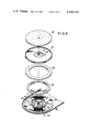
- FIG. 4 is an exploded perspective view of the turntable assembly of the record player shown on FIG. 2;
- FIG. 5 is a diagrammatic plan view of a rubber magnet for driving the turntable assembly of FIGS. 2-4;
- FIG. 6 is a plan view of a coil assembly for use in the turntable assembly of FIGS. 2-4;
- FIG. 7 is a partial enlarged plan view of a portion of the coil assembly shown in FIG. 6;
- FIG. 8 is a schematic perspective view to which reference will be made in explaining the operation of the drive mechanism for the turntable assembly of FIGS. 2-7;
- FIG. 9 is a cross-sectional view of a portion of a turntable assembly according to a second embodiment of this invention.
- FIG. 10 is a cross-sectional view of a turntable assembly according to a third embodiment of this invention.
- FIG. 11 is an exploded perspective view of a coil assembly included in the turntable assembly of FIG. 10.
- the turntable assembly 10 is shown to include a turntable 11, a base or chassis 12 and a DC brushless motor 13 mounted on the chassis 12 for driving the turntable 11.
- a permanent-magnet rotor 15 Within a casing 14 of the motor 13, there is provided a permanent-magnet rotor 15 and a stator 16.
- the rotor 15 includes a permanent-magnet rotor magnet 15a which is fixed to a rotor yoke 15b.
- the rotor yoke 15b is attached to a motor shaft 17 which is supported in casing 14 by a bearing 18, and which drives turntable 14.
- the stator 16 is constituted by coils wound around the bearing 18 of the motor 13, so as to face or confront the rotor magnet 15a. Electric current supplied to the coils of stator 16 is changed over in accordance with the detected position of the rotor magnet 15a so that a torque is generated for driving the magnet 15a, the rotor yoke 15b, the shaft 17, and thence, the turntable 11.
- the motor 13 occupies a substantial amount of space in the vertical or axial direction.
- the record player provided with turntable assembly 10 must be constructed with a substantially flat record player.
- the rotor magnet 15a has to be intensely magnetized and a high current has to be supplied to the coils of stator 16 in order to provide sufficient torque to drive the turntable 11.
- Relatively intense magnetic field emanate from rotor magnet 15a and also from the coils of stator 16 due to the high current. Therefore, a cap 19 is required to enclose the motor casing 14 and to prevent stray magnetic flux from interfering with a magnetic pick up cartridge used with the phonograph.
- a record player 20 is provided with a substantially flat casing 21.
- a circular, upwardly opening recess 22 is provided in casing 21 and receives a turntable 23.
- a tone arm 24 is mounted alongside the turntable 23 and an arrangement of touch switches 25 is also provided for controlling the operation of the phonograph 20.
- FIGS. 3 and 4 The construction of the turntable assembly of phonograph 20 is shown in greater detail on FIGS. 3 and 4.
- a through-hole 26 is formed to receive a spindle 27.
- the spindle 27 is provided with an integral flange 28 and a bearing sleeve 29.
- the flange 28 suitably secures turntable 23 to spindle 27, and sleeve 29 fits over a pivot shaft 30 by which turntable 23 is rotatably supported.
- a thrust bearing 31 (preferably of synthetic resin) is affixed to the top of the pivot shaft 30.
- a ball 32 is secured within the sleeve 29 at the top portion thereof so as to contact thrust bearing 31.
- the weight of turntable 23 is borne by thrust bearing 31 and ball 32.
- the pivot shaft 30 is shown to have an integral flange 33 which is suitably connected with a chassis plate 34 so that the latter supports pivot shaft 30.
- a stepped portion 35 is formed at the outer margin of chassis plate 34 to support the casing 21.
- support members 36 such as rubber feet, are attached to stepped portion 35.
- a rubber sheet or pad 37 is provided on turntable 23 to cushion a phonograph record when placed on the turntable 23.
- An annular rubber magnet 38 is attached to the underside of turntable 23 by an annular member 39 (FIG. 4).
- the magnet 38 is preferably molded of rubber mixed with a ferrite powder.
- Another type of magnet such as a sintered ferrite magnet may also be used.
- a large sintered ferrite magnet would be fragile and subject to fracturing.
- a large magnet can be easily manufactured by molding of rubber, and the resulting rubber magnet, such as, magnet 38, is not subject to such breakage.
- the rubber magnet 38 forms the rotor magnet of a brushless DC motor 40 for driving turntable 23, and the stator of such motor is constituted by coil assemblies 41.
- rubber magnet 38 is divided circumferentially into forty-eight sections.
- the sections denoted by "N” are polarized so that the lines of flux flow out of the drawing, while those sections denoted by “S” are polarized so that the lines of flux flow into the drawing.
- the sections N are magnetized so that the top or upper surfaces in the axial direction of spindle 27 are north magnetic poles, while their bottom or lower surfaces are south magnetic poles.
- the sections S are magnetized so that their upper surfaces are south magnetic poles and their lower surfaces are north magnetic poles.
- the sections of magnet 38 are magnetized so that the direction of magnetization of the annular rubber magnet 38 alternates from each section to the next adjacent section.
- turntable 23 acts as the rotor yoke for magnet 38.
- the flux from each section N of magnet 38 flows upwardly, and passes through the yoke formed by turntable 23 into both adjacent, oppositely-polarized sections S.
- two coil assemblies 41 are arranged directly beneath rubber magnet 38 so as to constitute the stator of motor 40.
- the coil assemblies 41 are each formed of a plurality of individual coils formed of wire wound around individual bobbins 42, and one of a pair of tongues 43, 44 formed integrally with chassis plate 34.
- the tongues 43, 44 penetrate hollow cores of the respective bobbins 42 and constitute the ferromagnetic cores for the coil assemblies 41.
- the tongues 43, 44 formed integrally with the chassis plate 34 are shaped as segments of a ring concentric with spindle 27 of the turntable.
- each of the coil assemblies 41 includes twenty-four coils 45a,46a,47a,45c,46c,47c,45d,46d,47d,45e,46e,47e,45f,46f,47f,45g,46g,47g,45h,46h and 47h wound on respective bobbins.
- the coil assemblies 41 are arranged symmetrically at diametrically opposite sides of the axis of spindle 27 and pivot shaft 30.
- the coil assemblies 41 are arranged so that each set of three adjacent coils subtends a rotational angle of 7.5° which angle is equal to the circumferential angle subtended by each section N or S of rubber magnet 38.
- each coil is arranged to subtend an angle of 2.5°, as shown in FIG. 7.
- the coils 45a,45b,45c,45d,45e,45f,45g, and 45h are connected together in series.
- the coils 46a,46b,46c,46d,46e,46f 46g,and 46h are connected in series, as are the coils 47a,47b,47c, 47d,47e,47f,47g, and 47h.
- a position detector is formed of three Hall elements 48 on a supporting plate 49 which is mounted on chassis plate 34 near one of the coil assemblies 41.
- the Hall element 48 are spaced from each other at angular intervals of 5° and are intended to sense the magnetic field of rubber magnet 38 and thereby detect the angularly position thereof; a suitable conventional electrical circuit (not shown) controlled by Hall element 48 may be provided to cause the current supplied through coils 45a-45h, 46a-46h, 47a-47h, in order, to be changed over in accordance with the detected position of magnet 38.
- the current i flowing through each coil assembly 41 crosses the magnetic flux B generated by rubber magnet 38. Consequently, each stator or coil assembly 41 is subjected to a force F determined by Fleming's left-hand rule, and rubber magnet 38 is subjected to an equal and opposite reaction force -F so that a driving torque is applied to turntable 23.
- the electrical circuitry for controlling the turntable assembly may be formed on a doughnut-shaped printed circuit board 50.
- the board 50 is arranged between turntable 23 and the chassis plate 34 and surrounds the pivot shaft 30. Electrical components, for example, as indicated at 51, are mounted on one surface of board 50 and are connected by conductive patterns printed on the other surface of the board.
- the thickness of the record player is substantially determined by the thickness of turntable 23, the thickness of rubber magnet 38, and the thickness of coil assemblies 41. Since turntable 23 together with magnet 38 constitutes the rotor of electric motor 40, and coil assemblies 41 on tongues 43, 44 integral with base 35 constitute the stator, it is apparent that the number of parts required to construct the record player is minimized. Furthermore, since rubber magnet 38 provides a substantial portion of the moment of inertia of the turntable 23, and the rubber magnet is dimensioned to be attached to turntable 23 in close proximity to the circumference of the latter, the turntable 23 is afforded an enhanced fly wheel effect, and smooth rotation of the turntable 23 is assured.
- the motor 40 enjoys a large lever arm as compared with conventional drive motors for turntable assemblies. Therefore, in the described example of this invention sufficient torque to rotate the turntable 23 is obtained, even though the rubber magnet 38 is weakly magnetized as compared with a rotor magnet in a conventional drive motor. Further, only a relatively small current need be applied to coil assemblies 41.
- coil assemblies 41 The construction of coil assemblies 41 is relatively simple.
- the individual coils 45a-45h, 46a-46h, 47a-47h, can be wound on bobbins 42 on an ordinary winding machine, and the bobbins can then be mounted on the respective tongues 43, 44 merely by inserting the latter through the hollow portions of the bobbins 42.
- the bobbins 42 can be easily fixed on the tongues 43, 44 by adhesive or the like.
- the turntable 23 serves as a yoke for rubber magnet 38, it acts as a shield to prevent magnetic flux from penetrating to the top side of the turntable 23.
- rubber magnet 38 can have a relatively low magnetization, as mentioned above, and the rubber magnet 38 is positioned near the periphery of the turntable 23 and relatively outside the outermost sound groove of a record disc to be supported on turntable 23.
- leakage magnetic flux from magnet 38 and from coil assemblies 41 is prevented from generating noise in a magnetic pick up cartridge located at the end of tone arm 24 when a record is being player on the turntable 23.
- FIG. 9 Another embodiment of the invention is shown in FIG. 9 in which elements corresponding to those in the previously described embodiment are identified by the same reference numerals, and the description thereof is omitted.
- the phonograph record player illustrated by FIG. 9 incorporates a yoke 55 which is U-shaped in cross-section, and is mounted between magnet 38 and turntable 23.
- the yoke 55 effectively prevents magnetic flux from leaking upward and interfering with the operation of a magnetic pick-up or cartridge.
- FIGS. 10 and 11 A third embodiment of the present invention is shown in FIGS. 10 and 11 in which, once again, the elements corresponding to those in the previously described embodiments are identified by the same reference numerals and the description thereof is omitted.
- the magnet 38 and the coil assemblies 41 are arranged opposite each other or confront in the vertical or axial direction.
- tongues 43,44 are arranged in a plane parallel to the turntable 23.
- the magnet 38' and coil assemblies 41' in the embodiment of FIGS. 10 and 11 are aligned or confront each other in the horizontal or radial direction. As shown, particularly on FIG.
- the tongues 43',44' are vertically formed at connecting portions 56,57, respectively, with the chassis plate 34.
- the tongues 43',44' are formed as portions of a cylinder which is concentric with the axis of turntable 23 and extends perpendicular to the plane chassis plate 34.
- the coil assemblies 41 are mounted on the tongues 43',44' and are arranged radially within the circular path of rubber magnet 38'. In other words, the annular rubber magnet 38' is arranged at a greater radial distance from the spindle 27 than are the coil assemblies 41'.
- the turntable 23 be manufactured by alternately layering sheets of rubber and plates of ferro magnetic material, such as steel.
- ferro magnetic material such as steel.
- the layered arrangement of the steel plates both protects and supports the rubber layers, and prevents the leakage of flux from affecting a magnetic cartridge on the tone arm 24.
Landscapes
- Engineering & Computer Science (AREA)
- Power Engineering (AREA)
- Rotational Drive Of Disk (AREA)
- Holding Or Fastening Of Disk On Rotational Shaft (AREA)
- Dc Machiner (AREA)
- Brushless Motors (AREA)
Applications Claiming Priority (2)
| Application Number | Priority Date | Filing Date | Title |
|---|---|---|---|
| JP1977127763U JPS5926789Y2 (ja) | 1977-09-22 | 1977-09-22 | レコ−ドプレ−ヤ |
| JP52-127763[U] | 1977-09-22 |
Publications (1)
| Publication Number | Publication Date |
|---|---|
| US4194743A true US4194743A (en) | 1980-03-25 |
Family
ID=14968081
Family Applications (1)
| Application Number | Title | Priority Date | Filing Date |
|---|---|---|---|
| US05/943,748 Expired - Lifetime US4194743A (en) | 1977-09-22 | 1978-09-19 | Record player |
Country Status (9)
| Country | Link |
|---|---|
| US (1) | US4194743A (de) |
| JP (1) | JPS5926789Y2 (de) |
| AT (1) | AT365797B (de) |
| AU (1) | AU517090B2 (de) |
| CA (1) | CA1100885A (de) |
| DE (1) | DE2841137A1 (de) |
| FR (1) | FR2404274B1 (de) |
| GB (1) | GB2005926B (de) |
| NL (1) | NL7809615A (de) |
Cited By (23)
| Publication number | Priority date | Publication date | Assignee | Title |
|---|---|---|---|---|
| US4417332A (en) * | 1981-06-15 | 1983-11-22 | Rca Corporation | Turntable speed control |
| US4499573A (en) * | 1981-07-20 | 1985-02-12 | Tokyo Shibaura Denki Kabushiki Kaisha | Disc rotating apparatus |
| US4509157A (en) * | 1981-07-20 | 1985-04-02 | Tokyo Shibaura Denki Kabushiki Kaisha | Disc player apparatus with an improved disc clamper |
| US4626727A (en) * | 1984-05-11 | 1986-12-02 | U.S. Philips Corporation | Flat, permanent magnet electric motor |
| US4731778A (en) * | 1985-10-22 | 1988-03-15 | U.S. Philips Corp. | Electro-magnetic drive unit comprising a pivotable armature |
| US4866321A (en) * | 1985-03-26 | 1989-09-12 | William C. Lamb | Brushless electrical machine for use as motor or generator |
| US4883982A (en) * | 1988-06-02 | 1989-11-28 | General Electric Company | Electronically commutated motor, blower integral therewith, and stationary and rotatable assemblies therefor |
| US4916345A (en) * | 1988-09-02 | 1990-04-10 | Chrysler Motors Corporation | Flat stator winding for alternator starter |
| US5117414A (en) * | 1988-09-19 | 1992-05-26 | Hewlett-Packard Company | Drive motor and spindle assembly for an optical disk drive |
| US5457676A (en) * | 1992-11-30 | 1995-10-10 | Daewoo Electronics Co., Ltd. | Turntable of a disk player with a resiliently biased magnet |
| US5463613A (en) * | 1992-03-27 | 1995-10-31 | Forsell; Peter | Motor drive unit for a record player |
| US5818133A (en) * | 1996-04-19 | 1998-10-06 | Siemens Canada Ltd. | Brushless motor with tubular bearing support |
| US5831359A (en) * | 1995-09-29 | 1998-11-03 | Papst Motoren Gmbh & Co. Kg | Electronically commutated motor with external rotor |
| GB2339627A (en) * | 1998-07-16 | 2000-02-02 | Ya Horng Electronic Co Ltd | A record player driving device |
| WO2000039037A1 (en) * | 1998-12-23 | 2000-07-06 | Antas S.P.A. | Glass forming apparatus with improved carousel mechanism and method for control thereof |
| USRE38178E1 (en) | 1980-05-10 | 2003-07-08 | Papst Licensing Gmbh & Co. Kg | Disk storage device having an underhub spindle motor |
| USRE38601E1 (en) | 1980-05-10 | 2004-09-28 | Papst Licensing, GmbH & Co. KG | Disk storage device having a radial magnetic yoke feature |
| USRE38662E1 (en) | 1980-05-10 | 2004-11-30 | Papst Licensing Gmbh & Co. Kg | Disk storage device having a sealed bearing tube |
| USRE38673E1 (en) | 1980-05-10 | 2004-12-21 | Papst Licensing Gmbh & Co. Kg | Disk storage device having a hub sealing member feature |
| USRE38772E1 (en) | 1981-03-18 | 2005-08-09 | Papst Licensing Gmbh & Co. Kg | Disk storage device having an undercut hub member |
| US10224069B1 (en) * | 2017-06-02 | 2019-03-05 | Nat Williams | Phonograph record turntable stabilizing assemblies and methods |
| US10381026B2 (en) * | 2017-07-10 | 2019-08-13 | Teac Corporation | Record player |
| US20200168243A1 (en) * | 2018-11-22 | 2020-05-28 | Yamaha Corporation | Audio device |
Families Citing this family (7)
| Publication number | Priority date | Publication date | Assignee | Title |
|---|---|---|---|---|
| FR2466075A1 (fr) * | 1979-09-21 | 1981-03-27 | Philips Ind Commerciale | Tourne-disque a plateau directement entraine par son moteur |
| JPS56137555A (en) * | 1980-03-27 | 1981-10-27 | Sony Corp | Optical disc cassette and disc driving method |
| DE3042497A1 (de) * | 1980-11-11 | 1982-07-29 | Magnet Bahn Gmbh | Elektrischer antrieb oder generator |
| JPS5860215A (ja) * | 1981-10-06 | 1983-04-09 | Hitachi Ltd | 位置検出付エンコ−ダ |
| US4491769A (en) * | 1982-05-24 | 1985-01-01 | Heidelberg Goetz | Rotary electric machine |
| DE3933868B4 (de) * | 1989-10-11 | 2004-07-01 | Robert Bosch Gmbh | Gebläse mit einem elektronisch kommutierten Antriebsmotor |
| WO2020240856A1 (ja) * | 2019-05-31 | 2020-12-03 | AlphaTheta株式会社 | 検出装置及び再生制御システム |
Citations (9)
| Publication number | Priority date | Publication date | Assignee | Title |
|---|---|---|---|---|
| US1915090A (en) * | 1930-07-30 | 1933-06-20 | Hammond Clock Company | Synchronous motor |
| US3218081A (en) * | 1960-05-26 | 1965-11-16 | Gentilini Augusto | Portable lightweight record-player |
| US3244423A (en) * | 1963-10-30 | 1966-04-05 | Vm Corp | Retractable tone arm support post for compact record changer |
| US3683248A (en) * | 1968-07-17 | 1972-08-08 | Matsushita Electric Industrial Co Ltd | Directly driven turntable apparatus for phonograph records |
| US3786288A (en) * | 1973-02-12 | 1974-01-15 | C Joannou | Phonograph record player turntable and motor assembly |
| US3872334A (en) * | 1972-04-14 | 1975-03-18 | Robert J Loubier | Integral rotor and gear assembly |
| US3988024A (en) * | 1974-06-14 | 1976-10-26 | Tokyo Shibaura Electric Co., Ltd. | Turntable apparatus |
| USRE29451E (en) | 1974-03-07 | 1977-10-18 | Light colored magnetic rubber | |
| US4131828A (en) * | 1976-12-14 | 1978-12-26 | Sanyo Electric Co., Ltd. | Apparatus for rotatively driving a turn table |
Family Cites Families (11)
| Publication number | Priority date | Publication date | Assignee | Title |
|---|---|---|---|---|
| US1480553A (en) * | 1922-07-03 | 1924-01-15 | Azor Motor Mfg Company | Phonograph motor |
| DE534319C (de) * | 1924-12-16 | 1931-09-24 | Eduard Uller | Elektrischer Stromerzeuger |
| GB366943A (en) * | 1930-11-04 | 1932-02-04 | Henry James Heasman | Improvements in or relating to electric gramophone motors |
| GB393617A (en) * | 1930-12-08 | 1933-06-07 | Gen Electric | Improvements in and relating to electric motors |
| US2242518A (en) * | 1940-01-02 | 1941-05-20 | Regan Day Inc | Turntable drive |
| US3253169A (en) * | 1963-02-20 | 1966-05-24 | Cons Electronics Ind | Synchronous motors |
| DE2039428C3 (de) * | 1970-08-07 | 1975-10-02 | Standard Elektrik Lorenz Ag, 7000 Stuttgart | Langsamlaufender Gleichstrommotor in Flachbauweise |
| FR2149610A5 (de) * | 1971-08-13 | 1973-03-30 | Poubeau Pierre | |
| GB1434192A (en) * | 1972-04-20 | 1976-05-05 | Mettoy Co Ltd | Electric motors |
| DE2345150C2 (de) * | 1973-09-07 | 1985-06-20 | Papst-Motoren GmbH & Co KG, 7742 St Georgen | Elektromotor |
| JPS5931303B2 (ja) * | 1976-02-27 | 1984-08-01 | ソニー株式会社 | 無接点モ−タ |
-
1977
- 1977-09-22 JP JP1977127763U patent/JPS5926789Y2/ja not_active Expired
-
1978
- 1978-09-15 AU AU39907/78A patent/AU517090B2/en not_active Expired
- 1978-09-19 US US05/943,748 patent/US4194743A/en not_active Expired - Lifetime
- 1978-09-20 CA CA311,679A patent/CA1100885A/en not_active Expired
- 1978-09-21 GB GB7837659A patent/GB2005926B/en not_active Expired
- 1978-09-21 NL NL7809615A patent/NL7809615A/xx not_active Application Discontinuation
- 1978-09-21 DE DE19782841137 patent/DE2841137A1/de not_active Withdrawn
- 1978-09-22 AT AT0686178A patent/AT365797B/de not_active IP Right Cessation
- 1978-09-22 FR FR7827213A patent/FR2404274B1/fr not_active Expired
Patent Citations (9)
| Publication number | Priority date | Publication date | Assignee | Title |
|---|---|---|---|---|
| US1915090A (en) * | 1930-07-30 | 1933-06-20 | Hammond Clock Company | Synchronous motor |
| US3218081A (en) * | 1960-05-26 | 1965-11-16 | Gentilini Augusto | Portable lightweight record-player |
| US3244423A (en) * | 1963-10-30 | 1966-04-05 | Vm Corp | Retractable tone arm support post for compact record changer |
| US3683248A (en) * | 1968-07-17 | 1972-08-08 | Matsushita Electric Industrial Co Ltd | Directly driven turntable apparatus for phonograph records |
| US3872334A (en) * | 1972-04-14 | 1975-03-18 | Robert J Loubier | Integral rotor and gear assembly |
| US3786288A (en) * | 1973-02-12 | 1974-01-15 | C Joannou | Phonograph record player turntable and motor assembly |
| USRE29451E (en) | 1974-03-07 | 1977-10-18 | Light colored magnetic rubber | |
| US3988024A (en) * | 1974-06-14 | 1976-10-26 | Tokyo Shibaura Electric Co., Ltd. | Turntable apparatus |
| US4131828A (en) * | 1976-12-14 | 1978-12-26 | Sanyo Electric Co., Ltd. | Apparatus for rotatively driving a turn table |
Cited By (25)
| Publication number | Priority date | Publication date | Assignee | Title |
|---|---|---|---|---|
| USRE38178E1 (en) | 1980-05-10 | 2003-07-08 | Papst Licensing Gmbh & Co. Kg | Disk storage device having an underhub spindle motor |
| USRE38673E1 (en) | 1980-05-10 | 2004-12-21 | Papst Licensing Gmbh & Co. Kg | Disk storage device having a hub sealing member feature |
| USRE38662E1 (en) | 1980-05-10 | 2004-11-30 | Papst Licensing Gmbh & Co. Kg | Disk storage device having a sealed bearing tube |
| USRE38601E1 (en) | 1980-05-10 | 2004-09-28 | Papst Licensing, GmbH & Co. KG | Disk storage device having a radial magnetic yoke feature |
| USRE38179E1 (en) | 1980-05-10 | 2003-07-08 | Papst Licensing Gmbh & Co. Kg | Disk storage device having a three-phase brushless DC underhub configured spindle motor |
| USRE38772E1 (en) | 1981-03-18 | 2005-08-09 | Papst Licensing Gmbh & Co. Kg | Disk storage device having an undercut hub member |
| US4417332A (en) * | 1981-06-15 | 1983-11-22 | Rca Corporation | Turntable speed control |
| US4499573A (en) * | 1981-07-20 | 1985-02-12 | Tokyo Shibaura Denki Kabushiki Kaisha | Disc rotating apparatus |
| US4509157A (en) * | 1981-07-20 | 1985-04-02 | Tokyo Shibaura Denki Kabushiki Kaisha | Disc player apparatus with an improved disc clamper |
| US4626727A (en) * | 1984-05-11 | 1986-12-02 | U.S. Philips Corporation | Flat, permanent magnet electric motor |
| US4866321A (en) * | 1985-03-26 | 1989-09-12 | William C. Lamb | Brushless electrical machine for use as motor or generator |
| US4731778A (en) * | 1985-10-22 | 1988-03-15 | U.S. Philips Corp. | Electro-magnetic drive unit comprising a pivotable armature |
| US4883982A (en) * | 1988-06-02 | 1989-11-28 | General Electric Company | Electronically commutated motor, blower integral therewith, and stationary and rotatable assemblies therefor |
| US4916345A (en) * | 1988-09-02 | 1990-04-10 | Chrysler Motors Corporation | Flat stator winding for alternator starter |
| US5117414A (en) * | 1988-09-19 | 1992-05-26 | Hewlett-Packard Company | Drive motor and spindle assembly for an optical disk drive |
| US5463613A (en) * | 1992-03-27 | 1995-10-31 | Forsell; Peter | Motor drive unit for a record player |
| US5457676A (en) * | 1992-11-30 | 1995-10-10 | Daewoo Electronics Co., Ltd. | Turntable of a disk player with a resiliently biased magnet |
| US5831359A (en) * | 1995-09-29 | 1998-11-03 | Papst Motoren Gmbh & Co. Kg | Electronically commutated motor with external rotor |
| US5818133A (en) * | 1996-04-19 | 1998-10-06 | Siemens Canada Ltd. | Brushless motor with tubular bearing support |
| GB2339627A (en) * | 1998-07-16 | 2000-02-02 | Ya Horng Electronic Co Ltd | A record player driving device |
| WO2000039037A1 (en) * | 1998-12-23 | 2000-07-06 | Antas S.P.A. | Glass forming apparatus with improved carousel mechanism and method for control thereof |
| US10224069B1 (en) * | 2017-06-02 | 2019-03-05 | Nat Williams | Phonograph record turntable stabilizing assemblies and methods |
| US10381026B2 (en) * | 2017-07-10 | 2019-08-13 | Teac Corporation | Record player |
| US20200168243A1 (en) * | 2018-11-22 | 2020-05-28 | Yamaha Corporation | Audio device |
| US10854221B2 (en) * | 2018-11-22 | 2020-12-01 | Yamaha Corporation | Audio device including non-contact power feeding mechanism |
Also Published As
| Publication number | Publication date |
|---|---|
| ATA686178A (de) | 1981-06-15 |
| FR2404274B1 (fr) | 1985-08-09 |
| FR2404274A1 (fr) | 1979-04-20 |
| DE2841137A1 (de) | 1979-04-05 |
| GB2005926A (en) | 1979-04-25 |
| JPS5926789Y2 (ja) | 1984-08-03 |
| AT365797B (de) | 1982-02-10 |
| CA1100885A (en) | 1981-05-12 |
| AU3990778A (en) | 1980-03-20 |
| JPS5454308U (de) | 1979-04-14 |
| NL7809615A (nl) | 1979-03-26 |
| GB2005926B (en) | 1982-03-31 |
| AU517090B2 (en) | 1981-07-09 |
Similar Documents
| Publication | Publication Date | Title |
|---|---|---|
| US4194743A (en) | Record player | |
| US5410201A (en) | Electric Motor | |
| US3845339A (en) | Permanent magnet rotor electric motor | |
| US4394594A (en) | Motor with a disk rotor | |
| US4125792A (en) | Brushless D-C motor | |
| CA1336787C (en) | In-spindle motor assembly for disk drive and method for fabricating the same | |
| US4174484A (en) | Motor with a disk rotor | |
| JPS5927988B2 (ja) | タ−ンテ−ブル装置 | |
| JPS6248295B2 (de) | ||
| USRE36016E (en) | Disc storage device having an integrated driving system | |
| KR900016994A (ko) | 가반식 vtr | |
| US5783884A (en) | Coil components and motor using the coil components | |
| JP2019110620A (ja) | スピンドルモータおよびそれを備えるディスク駆動装置 | |
| JP2985681B2 (ja) | ブラシレスモータ | |
| JPS6022796Y2 (ja) | 回転磁気ヘツド駆動装置 | |
| JPS605734Y2 (ja) | レコードプレーヤ | |
| JPH1132462A (ja) | 永久磁石モータおよびエレベーター | |
| GB2276771A (en) | Electric motor | |
| JPS581896Y2 (ja) | タ−ンテ−ブル駆動装置 | |
| JPH11236921A (ja) | スピンドルモータ | |
| JPH06335216A (ja) | ディスク用スピンドルモータ | |
| JPH04178149A (ja) | 電動機 | |
| JP2567214Y2 (ja) | モータ | |
| GB1592833A (en) | Rotary drive the rotational speed of which can be regulated | |
| JPH0632782Y2 (ja) | ブラシレスモ−タ用ロ−タ |