US4185357A - Furniture hinge component - Google Patents
Furniture hinge component Download PDFInfo
- Publication number
- US4185357A US4185357A US05/892,952 US89295278A US4185357A US 4185357 A US4185357 A US 4185357A US 89295278 A US89295278 A US 89295278A US 4185357 A US4185357 A US 4185357A
- Authority
- US
- United States
- Prior art keywords
- hinge
- carrier member
- fastener
- hinge arm
- carrier
- Prior art date
- Legal status (The legal status is an assumption and is not a legal conclusion. Google has not performed a legal analysis and makes no representation as to the accuracy of the status listed.)
- Expired - Lifetime
Links
- 238000006073 displacement reaction Methods 0.000 claims abstract description 10
- 239000002184 metal Substances 0.000 claims description 2
- 238000010276 construction Methods 0.000 description 4
- 238000006243 chemical reaction Methods 0.000 description 2
- 238000003780 insertion Methods 0.000 description 2
- 230000037431 insertion Effects 0.000 description 2
- 238000004873 anchoring Methods 0.000 description 1
- 239000000463 material Substances 0.000 description 1
- 238000012986 modification Methods 0.000 description 1
- 230000004048 modification Effects 0.000 description 1
- 230000035515 penetration Effects 0.000 description 1
Images


Classifications
-
- E—FIXED CONSTRUCTIONS
- E05—LOCKS; KEYS; WINDOW OR DOOR FITTINGS; SAFES
- E05D—HINGES OR SUSPENSION DEVICES FOR DOORS, WINDOWS OR WINGS
- E05D5/00—Construction of single parts, e.g. the parts for attachment
- E05D5/02—Parts for attachment, e.g. flaps
- E05D5/08—Parts for attachment, e.g. flaps of cylindrical shape
-
- E—FIXED CONSTRUCTIONS
- E05—LOCKS; KEYS; WINDOW OR DOOR FITTINGS; SAFES
- E05D—HINGES OR SUSPENSION DEVICES FOR DOORS, WINDOWS OR WINGS
- E05D7/00—Hinges or pivots of special construction
- E05D7/04—Hinges adjustable relative to the wing or the frame
- E05D7/0415—Hinges adjustable relative to the wing or the frame with adjusting drive means
- E05D7/0423—Screw-and-nut mechanisms
-
- E—FIXED CONSTRUCTIONS
- E05—LOCKS; KEYS; WINDOW OR DOOR FITTINGS; SAFES
- E05D—HINGES OR SUSPENSION DEVICES FOR DOORS, WINDOWS OR WINGS
- E05D7/00—Hinges or pivots of special construction
- E05D7/04—Hinges adjustable relative to the wing or the frame
- E05D2007/0461—Hinges adjustable relative to the wing or the frame in angular arrangement to the wing or the frame
-
- E—FIXED CONSTRUCTIONS
- E05—LOCKS; KEYS; WINDOW OR DOOR FITTINGS; SAFES
- E05D—HINGES OR SUSPENSION DEVICES FOR DOORS, WINDOWS OR WINGS
- E05D7/00—Hinges or pivots of special construction
- E05D7/04—Hinges adjustable relative to the wing or the frame
- E05D2007/0469—Hinges adjustable relative to the wing or the frame in an axial direction
-
- E—FIXED CONSTRUCTIONS
- E05—LOCKS; KEYS; WINDOW OR DOOR FITTINGS; SAFES
- E05D—HINGES OR SUSPENSION DEVICES FOR DOORS, WINDOWS OR WINGS
- E05D7/00—Hinges or pivots of special construction
- E05D7/04—Hinges adjustable relative to the wing or the frame
- E05D2007/0476—Pocket hinges
-
- E—FIXED CONSTRUCTIONS
- E05—LOCKS; KEYS; WINDOW OR DOOR FITTINGS; SAFES
- E05D—HINGES OR SUSPENSION DEVICES FOR DOORS, WINDOWS OR WINGS
- E05D7/00—Hinges or pivots of special construction
- E05D7/04—Hinges adjustable relative to the wing or the frame
- E05D2007/0484—Hinges adjustable relative to the wing or the frame in a radial direction
-
- E—FIXED CONSTRUCTIONS
- E05—LOCKS; KEYS; WINDOW OR DOOR FITTINGS; SAFES
- E05D—HINGES OR SUSPENSION DEVICES FOR DOORS, WINDOWS OR WINGS
- E05D7/00—Hinges or pivots of special construction
- E05D7/04—Hinges adjustable relative to the wing or the frame
-
- E—FIXED CONSTRUCTIONS
- E05—LOCKS; KEYS; WINDOW OR DOOR FITTINGS; SAFES
- E05Y—INDEXING SCHEME ASSOCIATED WITH SUBCLASSES E05D AND E05F, RELATING TO CONSTRUCTION ELEMENTS, ELECTRIC CONTROL, POWER SUPPLY, POWER SIGNAL OR TRANSMISSION, USER INTERFACES, MOUNTING OR COUPLING, DETAILS, ACCESSORIES, AUXILIARY OPERATIONS NOT OTHERWISE PROVIDED FOR, APPLICATION THEREOF
- E05Y2900/00—Application of doors, windows, wings or fittings thereof
- E05Y2900/20—Application of doors, windows, wings or fittings thereof for furniture, e.g. cabinets
Definitions
- This invention relates to a furniture hinge for pivotally connecting two parts of a piece of furniture, and more particularly to a hinge for pivoting a door to the frame of a piece of furniture.
- a conventional furniture hinge comprises a first hinge component mounted on one part of a piece of furniture, a second hinge component mounted on the other part of the piece of furniture, and a pivotal connection between the components for effecting pivotal movement of one part of the piece of furniture relative to the other.
- a known type of hinge component includes a cup-shaped fastener member anchored in a counter-sunk bore in a surface of one of the parts of the piece of furniture, and a hinge arm that is adjustably seated in the cup-shaped fastener for permitting limited adjustment to the hinge arm member which carries a hinge shaft that defines the pivotal axis of the hinge.
- the hinge arm member Despite its relative complex design, such a hinge component permits the hinge arm member to be adjusted along only a single axis that is transverse and perpendicular to the axis of the pivot shaft. Manufacturers of contemporary furniture, however, have increasing need for hinges that also permit the hinge arm member to be adjusted along an axis parallel to the axis of the hinge shaft.
- the hinge arm member should be adjustable along three mutually perpendicular axes, namely, along an axis perpendicular and parallel to the surface of one of the parts of the piece of furniture, and along axes perpendicular and parallel to the axis of the hinge shaft.
- a hinge component according to the present invention comprises a fastener member adapted to be attached to one part of a piece of furniture; a carrier member mounted in a cavity within the fastener member for adjustable displacement along a first axis; and a hinge arm member which carries a hinge shaft defining the pivotal axis of the hinge component.
- the hinge army member is mounted in a guide groove formed in the carrier member for adjustable displacement relative thereto along a second axis perpendicular to the first axis.
- the hinge member is releasably clamped between the carrier member and the fastener member by a fastener passing between the two last mentioned members.
- the hinge arm member can be adjustably displaced relative to both the fastener and the carrier member along a third axis perpendicular to both the first and second axes by utilizing an adjustment screw engaging the hinge arm member and the fastener member.
- the hinge shaft carried by the hinge arm member can be adjusted along three mutually perpendicular axes.
- the carrier member preferably comprises a disc-like plate provided on one surface with the guide groove which receives a tongue on the hinge arm member.
- the guide groove at least in the vicinity of the portion receiving the fastener, is shallower than the tongue and faces a wall segment of the fastener member which is cup-like in construction.
- a single threaded fastener passing through the wall segment and threaded into the carrier member will clamp the tongue of the hinge arm member between the carrier member and the fastener member to define a hinge component according to the present invention which is particularly simple in design and economical in construction yet will provide the required degrees of adjustment for the hinge shaft of the component.
- FIG. 1 is an exploded perspective view of a hinge component according to the present invention including a fastener member adapted to be attached to a side wall of a piece of furniture, a carrier member, and a hinge arm member carrying a hinge shaft defining the pivotal axis of the hinge component;
- FIG. 1A is a perspective view of the hinge arm member of FIG. 1 but in a position rotated about 180° about the axis of the hinge shaft;
- FIG. 2 is a perspective view of the hinge arm member mounted on the carrier member
- FIG. 3 is a rear, perspective view of the fastener member showing its cup-like construction, and a preassembly consisting of the hinge arm member preassembled on the carrier member prior to insertion of the preassembly into the fastener member;
- FIG. 4 is similar in FIG. 3 except the preassembly is shown inserted into the fastener member;
- FIG. 5 is a perspective view of a completely assembled hinge component according to the present invention prior to mounting of the same into a side wall of the piece of furniture provided with a counter-sunk bore for receiving the fastener member;
- FIG. 6 is a view similar to FIG. 5 but showing the hinge component mounted on the piece of furniture
- FIG. 7 is a front view of the hinge component mounted on a piece of furniture
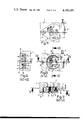
- FIG. 8 is a section along the line I--I of FIG. 9;
- FIG. 9 is a section taken along the line II--II of FIG. 8;
- FIG. 10 is a section taken along the line III--III of FIG. 9;
- FIG. 11 is similar to FIG. 7 but shows another position of the hinge arm member of the fastener member
- FIG. 12 is a section taken along the line IV--IV of FIG. 13;
- FIG. 13 is a section taken along the line V--V of FIG. 12.
- FIG. 14 is a section taken along the line VI--VI of FIG. 13.
- reference numeral 1 designates a hinge component according to the present invention mounted in side wall 3 of a piece of furniture.
- Component 1 comprises a single hinge shaft 2 that is spaced from edge 3' of wall 3 which contains counter-sunk bore 4 that opens into edge 3'.
- Barb-like ribs 6 formed on the outer periphery of the cup-shaped portion of fastener member 5 anchor the component in bore 4 such that flat segment 7 on member 5 is flush with edge 3' of side wall 3 of the piece of furniture.
- fastener member 5 includes wall segment 9 defining the bottom of the cup-shaped member and an interrupted cylindrical wall perpendicular to segment 9. Cavity 8 is closed after member 5 is seated in bore 4 (see FIG. 6).
- Support member 10 is disc-shaped and fits into cavity 8.
- One surface of member 10 is provided with lengthwise guide groove 11 (FIG. 1) extending from edge-to-edge, the groove having a generally U-shaped cross-section with a bottom surface that includes support face 12 adjacent one edge.
- Sides 13 and 14 defining the groove are formed by two wall segments that extend in a lengthwise direction, i.e., in the direction of double arrow A.
- the width of groove 11 corresponds to the width of tongue 15 on hinge arm member 16 carrying hinge shaft 2 whose axis defines the pivotal axis of the hinge component.
- Tongue 15 is thicker than the depth of at least a part of groove 11 and is slidably received therein for movement in the direction of double arrow A (see FIG. 1).
- guide pins 17 and 18 on faces 13 and 14 of carrier member 10 face wall segment 9 of fastener member 5, and seat in guide slots 19 and 20 (see FIG. 10) located on the inside of wall segment 9 when carrier member 10 is nested in cavity 8 of member 5.
- Slots 19 and 20 extend in a direction parallel to the direction of hinge shaft 2 when the members are assembled into the component, that is, in the direction of double arrow B (FIG. 1).
- Guide pin 17 and 18, together with guide slots 19 and 20 permit adjustment of the carrier member 10 on fastener member 5 in the direction of double arrow B.
- a single screw 21 is used to attach hinge arm member 16 to both carrier member 10 and fastener member 5.
- Screw 21 passes through slotted hole 22 (FIGS. 5 and 6) in wall segment 9 and through clearance slot 23 of tongue 15 to engage threaded hole 24 in the bottom surface of guide groove 11, i.e., in the adjacent support face 12 of the carrier member. Because the depth of groove 11 in the region adjacent hole 24 is less than the thickness of tongue 15, hinge arm member 16 will be clamped between the bottom surface of guide groove 11 and the inside of wall segment 9 of fastener member 5 when screw 21 is threaded into hole 24.
- a threaded hole 25 is provided in tongue 15 for receiving adjustment screw 26 whose head is received in recess 27 (see FIGS. 8 and 12) on the inner surface of wall segment 9 of fastener member 5.
- Slot 29 in wall segment 9 is elongated in the direction of double arrow B and opens into recess 27 to provide clearance for a tool, such as a screw driver, to pass through wall 9 into recess 27 and engage slot 28 in the head of adjustment screw 26 when the latter is threaded into hole 25.
- Recess 27 is large enough in the directions of double arrows A and B to permit clearance for the head of screw 26 as the hinge arm member 16 is moved in the direction of double arrow A relative to carrier member 10 and as the assembly of hinge arm member 16 and carrier member 10 is moved in the direction of double arrow B relative to fastener member 5.
- Face 12 associated with groove 11 in member 10 is inclined as indicated in FIGS. 8 and 12 to provide clearance for pivotal movement of tongue 15 about an axis parallel to double arrow B and passing through screw 21. Such movement occurs in response to rotation of screw 26 which moves hinge shaft 2 along the axis designated by double arrow C. The direction of movement depends on direction of rotation of screw 26 relative to threaded hole 25.
- carrier member 10 In assembling the members of hinge component 1, carrier member 10 is first nested in cavity 8 of fastener member 5 by seating pins 17 and 18 in guide slots 19 and 20 on wall surface 9. Then, screw 21 is partially threaded into hole 24 thereby loosely holding members 5 and 10 together with interruption 30 of the cylindrical wall of member 5 (FIG. 1) aligned with slot 11 in member 10. Tongue 15 of hinge arm member 16, into which screw 26 has been preassembled, is inserted through interruption 30 into sliding engagement with groove 11, slot 23 in the tongue providing clearance for screw 21. Insertion of tongue 15 continues until the slotted head of screw 26 is contained within recess 27 in wall segment 9. After this occurs, screw 21 can be threaded further into hole 24 until adjustment screw 26 is captured in the recess thereby retaining the hinge arm member to both the fastener member and carrier member.
- hinge component 1 can be attached to the piece of furniture by forcing fastener member 5 into bore 4 in side wall 3 of the furniture. Even though screw 21 is not as yet fully tightened, the hinge component will be able to absorb the weight of a door when it is attached to the hinge component because of the reaction between tongue 15 and groove 11 which limits relative movement of the hinge arm in the direction of double arrow A and the reaction of pins 17 and 18 in slots 19 and 20 which limit movement of members 10 and 16 in the direction of double arrow B. Before screw 21 is fully tightened into hole 24, hinge shaft 2 can be adjusted to compensate for dimensional tolerances along the three coordinate axes denoted by the double arrows A, B and C.
- the axis of hinge shaft 2 can be moved in the direction of double arrow A, i.e., in a direction parallel to surface 3" of the furniture and perpendicular to end face 3', in the direction of double arrow B (i.e., in a direction parallel to surface 3" and parallel to end face 3'), and also in the direction of double arrow C (i.e., in a direction parallel to end face 3' and perpendicular to surface 3").
- adjustment screw 26 is chosen to fit entirely within recess 27 and surface 12 as shown in FIGS. 8 and 12. Consequently, the slotted head of screw 26 will seat against the inside surface of recess 27 while the free threaded end of the screw will seat surface 12. After screw 26 is rotated until shaft 2 is in the selected position, further tightening of screw 21 will preclude further rotation of screw 26 thus ensuring stability in the selected attitude of hinge arm shaft 2. Thus, in the hinge component of the present invention, only a single screw is used to interlock all of the members.
- the hinge component of the present invention permits a considerable displacement of hinge shaft 2 along three mutually perpendicular axes corresponding to double arrows A, B and C.
- the position of the axis of hinge arm 2 relative to end face 3' of the furniture can be minimized in the manner shown in FIGS. 7-9, by sliding tongue 15 inwardly relative to carrier member 10 as far as possible and by tilting the hinge arm member until it contacts support surface 12 of member 10 as shown in FIG. 8.
- the hinge shaft 2 can be moved in the direction of double arrow B by sliding member 10 through the displacement b as indicated in FIG. 9.
- FIGS. 11-14 show a setting of hinge arm members 16 by which the hinge is shifted by a maximum amount b in the direction of double arrow B while the hinge shaft 2 is positioned at a maximum distance from end face 3' and from outer surface 3'" of the side wall three of the piece of furniture.
- the range of adjustment of hinge arm 16 and consequently the adjustment of hinge shaft 2 is enhanced by inclining the inside of surface of wall segment 9 from the region of slot 22 where the thickness of the wall section is a maximum as shown in FIGS. 8 and 12.
- the support surfaces of carrier member 10 facing the inside surface of wall segment 9 are likewise inclined as shown in FIGS. 8 and 12 thereby permitting maximum displacement of hinge arm member 16 about an axis passing perpendicularly through screw 21 in a direction parallel to the double arrow B.
- the member 15 In order to limit the depth of penetration of fastener member 5 into the seating bore 4, the member 15 provided with projecting flange 35 (FIG. 1) on the surface of wall segment 9 that is exposed when the fastener is mounted in the side wall piece of furniture. Such flange rests against the inside surface 3" of the side wall 3' of the piece of furniture surrounding bore 4. Flange 35 narrows into a triangular tang containing hole 36 through which an additional anchoring screw 37 can be inserted as shown in FIGS. 8 and 12.
- hinge arm member 16 and fastener member 5 are preferably metal. However, a tough plastic can be used to make members 5 and 10.
Landscapes
- Engineering & Computer Science (AREA)
- Mechanical Engineering (AREA)
- Hinges (AREA)
Applications Claiming Priority (2)
| Application Number | Priority Date | Filing Date | Title |
|---|---|---|---|
| DE2723850 | 1977-05-26 | ||
| DE2723850A DE2723850C2 (de) | 1977-05-26 | 1977-05-26 | Möbelscharnier |
Publications (1)
| Publication Number | Publication Date |
|---|---|
| US4185357A true US4185357A (en) | 1980-01-29 |
Family
ID=6009974
Family Applications (1)
| Application Number | Title | Priority Date | Filing Date |
|---|---|---|---|
| US05/892,952 Expired - Lifetime US4185357A (en) | 1977-05-26 | 1978-04-03 | Furniture hinge component |
Country Status (11)
| Country | Link |
|---|---|
| US (1) | US4185357A (es) |
| JP (1) | JPS594018B2 (es) |
| AT (1) | AT373028B (es) |
| AU (1) | AU518980B2 (es) |
| BR (1) | BR7801727A (es) |
| DE (1) | DE2723850C2 (es) |
| ES (1) | ES246992Y (es) |
| FR (1) | FR2392206A1 (es) |
| GB (1) | GB1584028A (es) |
| IT (1) | IT1095618B (es) |
| PT (1) | PT67842B (es) |
Cited By (27)
| Publication number | Priority date | Publication date | Assignee | Title |
|---|---|---|---|---|
| US4338699A (en) * | 1979-05-07 | 1982-07-13 | Julius Blum Gesellschaft M.B.H. | Furniture hinge |
| US4376324A (en) * | 1980-09-26 | 1983-03-15 | Mepla, Inc. | Furniture hinge |
| US5339493A (en) * | 1992-10-30 | 1994-08-23 | Macintyre Robert J | Adjustable hinge |
| US5839164A (en) * | 1996-03-05 | 1998-11-24 | Newell Operating Company | Cabinet hinge with press-in mounting cup |
| WO1999061738A2 (en) * | 1998-05-13 | 1999-12-02 | Frip Ab | Hinge device of the snap-in type |
| US6049946A (en) * | 1998-06-08 | 2000-04-18 | Newell Operating Company | Adjustable hinge |
| US6058564A (en) * | 1998-02-26 | 2000-05-09 | Newell Operating Company | Adjustable hinge |
| US6128807A (en) * | 1997-11-22 | 2000-10-10 | Samsung Electronics Co., Ltd. | Refrigerator with a removable hinge pin |
| GB2353820A (en) * | 1999-08-28 | 2001-03-07 | Breck Charles Macey | Adjustable hinge pin |
| US6286185B1 (en) * | 1998-03-17 | 2001-09-11 | Dieter Ramsauer | Hinge for metal cupboard doors |
| US6334732B1 (en) * | 1997-08-12 | 2002-01-01 | Syma Intercontinental Ag | Closing bushing for a clamping device used for removably connecting two profiled parts |
| EP1394346A1 (en) * | 2002-09-02 | 2004-03-03 | Alan Roger Zebedee | Hinge |
| US6760955B2 (en) * | 1999-02-11 | 2004-07-13 | Arturo Salice S.P.A. | Apparatus to fasten a fitting, preferably the support arm of a hinge, to a panel of a piece of furniture or the like |
| US20070022568A1 (en) * | 2003-12-08 | 2007-02-01 | Gaydos Christopher C | Railroad car hatch cover hinge structure and method for connecting a hatch cover to a railcar |
| US7603746B1 (en) | 2002-09-20 | 2009-10-20 | G-U Hardware, Inc. | Adjustable butt hinges for doors |
| US20100033067A1 (en) * | 2008-08-11 | 2010-02-11 | Samsung Electronics Co., Ltd. | Refrigerator with step adjustment device |
| US20100281652A1 (en) * | 2009-05-11 | 2010-11-11 | Sugatsune Kogyo Co., Ltd. | cup embedded type hinge device with position adjustment function |
| US20140096343A1 (en) * | 2012-10-04 | 2014-04-10 | Katoh Electrical Machinery Co., Ltd. | Slide Hinge |
| US20160378146A1 (en) * | 2015-06-27 | 2016-12-29 | Intel Corporation | Fastenerless Hinge which Enables Thin Form Factor Low Cost Design |
| WO2018158151A3 (de) * | 2017-02-28 | 2018-11-01 | ambigence GmbH & Co. KG | Bauplatte für eine möbelwand, verfahren zur herstellung einer solchen bauplatte und einer möbelwand sowie möbelkorpus oder möbel mit einer möbelwand |
| US10221599B2 (en) | 2013-09-27 | 2019-03-05 | Bombardier Inc. | Adjustment device |
| CN111719978A (zh) * | 2020-06-12 | 2020-09-29 | 杭州康利达卫浴有限公司 | 一种通用连接件、连接组件及淋浴房 |
| US11111709B1 (en) * | 2020-10-06 | 2021-09-07 | Jorge Santa | Adjustable hinge repair assembly |
| US20220018171A1 (en) * | 2020-07-20 | 2022-01-20 | Maax Bath Inc. | Shower door hinge assembly |
| USD960697S1 (en) | 2016-12-14 | 2022-08-16 | Franz Baur | Connecting device |
| US11614113B2 (en) | 2016-02-17 | 2023-03-28 | Franz Baur | Connecting means and method for connecting two components |
| US20230203864A1 (en) * | 2020-05-20 | 2023-06-29 | D & D Group Pty Ltd | Improvements to hinges or the like |
Families Citing this family (12)
| Publication number | Priority date | Publication date | Assignee | Title |
|---|---|---|---|---|
| AT386861B (de) * | 1982-04-19 | 1988-10-25 | Grass Alfred Metallwaren | Tuerscharnier mit einstellanordnung zur seitenund hoeheneinstellung |
| JPS60108665U (ja) * | 1983-12-28 | 1985-07-24 | 木村新株式会社 | 家具用蝶番 |
| US4671582A (en) * | 1985-11-08 | 1987-06-09 | Anthony's Manufacturing Company, Inc. | Combined, plug-in hinge pin and double-ended electrical connector for a hinged appliance door, with mating receptacle and connectors |
| US4805928A (en) * | 1986-07-23 | 1989-02-21 | Combi Co., Ltd. | Reclining mechanism of baby carriage |
| NO165354C (no) * | 1987-07-28 | 1991-01-30 | Grorud Jernvarefab As | Doerhengsel for tunge doerer. |
| GB2225608A (en) * | 1988-11-14 | 1990-06-06 | Philip Arnold Mundye | Adjustable hinge system |
| DE3943210C1 (es) * | 1989-12-28 | 1991-06-20 | Arturo Salice S.P.A., Novedrate, Como, It | |
| DE4307067C2 (de) * | 1993-03-06 | 1995-03-09 | Heine & Sohn Anuba Beschlaege | Tür- oder Fensterband |
| DE4421056C2 (de) * | 1994-06-17 | 1996-04-18 | Simonswerk Gmbh | Scharniereinrichtung |
| DE29511756U1 (de) * | 1995-07-20 | 1995-09-28 | Ferco Int Usine Ferrures | Flügelseitiges Ecklagerbeschlagteil für Drehkippfenster |
| BE1010648A3 (nl) * | 1996-09-25 | 1998-11-03 | Parys Remi E Van | Scharnierconstructie en daarbij gebruikte onderdelen. |
| DE20105413U1 (de) * | 2001-03-28 | 2002-08-08 | Niemann Hans Dieter | Tür- oder Fensterband |
Citations (5)
| Publication number | Priority date | Publication date | Assignee | Title |
|---|---|---|---|---|
| DE2432158A1 (de) * | 1974-07-04 | 1976-01-22 | Heinze Fa R | Spiegelklammer |
| DE2439252A1 (de) * | 1974-08-16 | 1976-03-04 | Hettich Hetal Werke | Scharnier |
| DE2542462A1 (de) * | 1975-09-24 | 1977-03-31 | Schulte Gmbh & Co Ewald | Scharnier |
| DE2554129A1 (de) * | 1975-12-02 | 1977-06-16 | Heinze Fa R | Moebelscharnier |
| DE2554133A1 (de) * | 1975-12-02 | 1977-06-16 | Heinze Fa R | Moebelscharnier |
Family Cites Families (5)
| Publication number | Priority date | Publication date | Assignee | Title |
|---|---|---|---|---|
| DE1784115A1 (de) * | 1968-07-09 | 1972-01-27 | Schwarte Fitschenfab Franz | Zargenband |
| DE2313451C3 (de) * | 1973-03-17 | 1981-11-19 | Prämeta Präzisionsmetall- u. Kunststofferzeugnisse G. Baumann & Co, 5000 Köln | Scharnierband in verdeckter Anordnung für aufliegende Türflügel, insbesondere Möbelscharnier |
| DE2438495A1 (de) * | 1974-08-10 | 1976-02-26 | Heinze Fa R | Scharnier zum gelenkigen verbinden zweier bauteile |
| DE2648095C2 (de) * | 1976-10-23 | 1985-09-05 | Fa. Richard Heinze, 4900 Herford | Scharnier |
| BR7706984A (pt) * | 1976-10-22 | 1978-06-27 | Heinze R | Dobradica para moveis |
-
1977
- 1977-05-26 DE DE2723850A patent/DE2723850C2/de not_active Expired
- 1977-12-28 AT AT0934777A patent/AT373028B/de not_active IP Right Cessation
-
1978
- 1978-02-14 FR FR7804968A patent/FR2392206A1/fr active Granted
- 1978-03-21 BR BR7801727A patent/BR7801727A/pt unknown
- 1978-03-29 PT PT67842A patent/PT67842B/pt unknown
- 1978-04-03 US US05/892,952 patent/US4185357A/en not_active Expired - Lifetime
- 1978-04-28 GB GB16887/78A patent/GB1584028A/en not_active Expired
- 1978-04-28 IT IT22865/78A patent/IT1095618B/it active
- 1978-05-13 JP JP53057073A patent/JPS594018B2/ja not_active Expired
- 1978-05-24 ES ES1978246992U patent/ES246992Y/es not_active Expired
- 1978-05-25 AU AU36465/78A patent/AU518980B2/en not_active Expired
Patent Citations (5)
| Publication number | Priority date | Publication date | Assignee | Title |
|---|---|---|---|---|
| DE2432158A1 (de) * | 1974-07-04 | 1976-01-22 | Heinze Fa R | Spiegelklammer |
| DE2439252A1 (de) * | 1974-08-16 | 1976-03-04 | Hettich Hetal Werke | Scharnier |
| DE2542462A1 (de) * | 1975-09-24 | 1977-03-31 | Schulte Gmbh & Co Ewald | Scharnier |
| DE2554129A1 (de) * | 1975-12-02 | 1977-06-16 | Heinze Fa R | Moebelscharnier |
| DE2554133A1 (de) * | 1975-12-02 | 1977-06-16 | Heinze Fa R | Moebelscharnier |
Cited By (51)
| Publication number | Priority date | Publication date | Assignee | Title |
|---|---|---|---|---|
| US4338699A (en) * | 1979-05-07 | 1982-07-13 | Julius Blum Gesellschaft M.B.H. | Furniture hinge |
| US4376324A (en) * | 1980-09-26 | 1983-03-15 | Mepla, Inc. | Furniture hinge |
| US4470169A (en) * | 1980-09-26 | 1984-09-11 | Mepla, Inc. | Articulated hinge with over-center mechanism having a two-arm cam lever |
| US5339493A (en) * | 1992-10-30 | 1994-08-23 | Macintyre Robert J | Adjustable hinge |
| US5839164A (en) * | 1996-03-05 | 1998-11-24 | Newell Operating Company | Cabinet hinge with press-in mounting cup |
| US6334732B1 (en) * | 1997-08-12 | 2002-01-01 | Syma Intercontinental Ag | Closing bushing for a clamping device used for removably connecting two profiled parts |
| US6128807A (en) * | 1997-11-22 | 2000-10-10 | Samsung Electronics Co., Ltd. | Refrigerator with a removable hinge pin |
| US6058564A (en) * | 1998-02-26 | 2000-05-09 | Newell Operating Company | Adjustable hinge |
| US6286185B1 (en) * | 1998-03-17 | 2001-09-11 | Dieter Ramsauer | Hinge for metal cupboard doors |
| US6715181B1 (en) | 1998-05-13 | 2004-04-06 | Frip Ab | Hinge device of the snap-in type |
| WO1999061738A3 (en) * | 1998-05-13 | 2000-03-02 | Trioving As | Hinge device of the snap-in type |
| GB2354798A (en) * | 1998-05-13 | 2001-04-04 | Ab Frip | Hinge device of the snap-in type |
| WO1999061738A2 (en) * | 1998-05-13 | 1999-12-02 | Frip Ab | Hinge device of the snap-in type |
| GB2354798B (en) * | 1998-05-13 | 2002-12-24 | Ab Frip | Hinge device of the snap-in type |
| US6049946A (en) * | 1998-06-08 | 2000-04-18 | Newell Operating Company | Adjustable hinge |
| US6760955B2 (en) * | 1999-02-11 | 2004-07-13 | Arturo Salice S.P.A. | Apparatus to fasten a fitting, preferably the support arm of a hinge, to a panel of a piece of furniture or the like |
| GB2353820A (en) * | 1999-08-28 | 2001-03-07 | Breck Charles Macey | Adjustable hinge pin |
| US20040040116A1 (en) * | 2002-09-02 | 2004-03-04 | Zebedee Alan R. | Hinge |
| EP1394346A1 (en) * | 2002-09-02 | 2004-03-03 | Alan Roger Zebedee | Hinge |
| US6925683B2 (en) | 2002-09-02 | 2005-08-09 | Alan R Zebedee | Hinge |
| GB2394749B (en) * | 2002-09-02 | 2005-09-07 | Alan Roger Zebedee | Hinge |
| US7603746B1 (en) | 2002-09-20 | 2009-10-20 | G-U Hardware, Inc. | Adjustable butt hinges for doors |
| US20080209678A1 (en) * | 2003-12-08 | 2008-09-04 | Gaydos Christopher C | Hinge system for povotally connecting a first member to a second member |
| US7810436B2 (en) | 2003-12-08 | 2010-10-12 | Miner Enterprises, Inc. | Hinge system for pivotally connecting a first member to a second member |
| US20070022568A1 (en) * | 2003-12-08 | 2007-02-01 | Gaydos Christopher C | Railroad car hatch cover hinge structure and method for connecting a hatch cover to a railcar |
| US7387075B2 (en) | 2003-12-08 | 2008-06-17 | Miner Enterprises, Inc. | Method for mounting a hatch cover to a railcar |
| US8506026B2 (en) * | 2008-08-11 | 2013-08-13 | Samsung Electronics Co., Ltd. | Refrigerator with step adjustment device |
| US20100033067A1 (en) * | 2008-08-11 | 2010-02-11 | Samsung Electronics Co., Ltd. | Refrigerator with step adjustment device |
| US20100281652A1 (en) * | 2009-05-11 | 2010-11-11 | Sugatsune Kogyo Co., Ltd. | cup embedded type hinge device with position adjustment function |
| US8250705B2 (en) * | 2009-05-11 | 2012-08-28 | Sugatsune Kogyo Co., Ltd. | Hinge cup with position adjustment function |
| US20140096343A1 (en) * | 2012-10-04 | 2014-04-10 | Katoh Electrical Machinery Co., Ltd. | Slide Hinge |
| US8938857B2 (en) * | 2012-10-04 | 2015-01-27 | Katoh Electrical Machinery Co., Ltd. | Slide hinge |
| US10221599B2 (en) | 2013-09-27 | 2019-03-05 | Bombardier Inc. | Adjustment device |
| US10435932B2 (en) * | 2015-06-27 | 2019-10-08 | Intel Corporation | Fastenerless hinge which enables thin form factor low cost design |
| US20160378146A1 (en) * | 2015-06-27 | 2016-12-29 | Intel Corporation | Fastenerless Hinge which Enables Thin Form Factor Low Cost Design |
| US9703327B2 (en) * | 2015-06-27 | 2017-07-11 | Intel Corporation | Fastenerless hinge which enables thin form factor low cost design |
| US11614113B2 (en) | 2016-02-17 | 2023-03-28 | Franz Baur | Connecting means and method for connecting two components |
| US11885356B2 (en) | 2016-02-17 | 2024-01-30 | Franz Baur | Connecting means and method for connecting two components |
| US11629741B2 (en) * | 2016-02-17 | 2023-04-18 | Franz Baur | Connecting device and method for connecting two components |
| USD960697S1 (en) | 2016-12-14 | 2022-08-16 | Franz Baur | Connecting device |
| WO2018158151A3 (de) * | 2017-02-28 | 2018-11-01 | ambigence GmbH & Co. KG | Bauplatte für eine möbelwand, verfahren zur herstellung einer solchen bauplatte und einer möbelwand sowie möbelkorpus oder möbel mit einer möbelwand |
| CN110520016A (zh) * | 2017-02-28 | 2019-11-29 | 安必根斯有限及两合公司 | 家具件侧面用构造板、生产该类构造板和家具件侧面的方法及具有侧面的家具主体或家具件 |
| CN110520016B (zh) * | 2017-02-28 | 2022-03-04 | 安必根斯有限及两合公司 | 家具件侧面用构造板、生产该类构造板和家具件侧面的方法及具有侧面的家具主体或家具件 |
| US11350747B2 (en) | 2017-02-28 | 2022-06-07 | ambigence GmbH & Co. KG | Construction panel for a side of an item of furniture, method for producing said type of construction panel and side of an item of furniture and furniture body or item of furniture having a side |
| US20230203864A1 (en) * | 2020-05-20 | 2023-06-29 | D & D Group Pty Ltd | Improvements to hinges or the like |
| CN111719978B (zh) * | 2020-06-12 | 2023-10-20 | 杭州康利达卫浴有限公司 | 一种通用连接件、连接组件及淋浴房 |
| CN111719978A (zh) * | 2020-06-12 | 2020-09-29 | 杭州康利达卫浴有限公司 | 一种通用连接件、连接组件及淋浴房 |
| US20220018171A1 (en) * | 2020-07-20 | 2022-01-20 | Maax Bath Inc. | Shower door hinge assembly |
| US11702873B2 (en) * | 2020-07-20 | 2023-07-18 | Maax Bath Inc. | Shower door hinge assembly |
| US11952818B2 (en) * | 2020-07-20 | 2024-04-09 | Maax Bath Inc. | Shower door hinge assembly |
| US11111709B1 (en) * | 2020-10-06 | 2021-09-07 | Jorge Santa | Adjustable hinge repair assembly |
Also Published As
| Publication number | Publication date |
|---|---|
| JPS594018B2 (ja) | 1984-01-27 |
| FR2392206A1 (fr) | 1978-12-22 |
| GB1584028A (en) | 1981-02-04 |
| ES246992Y (es) | 1980-12-16 |
| ATA934777A (de) | 1983-04-15 |
| PT67842A (de) | 1978-04-01 |
| BR7801727A (pt) | 1978-12-05 |
| JPS5416268A (en) | 1979-02-06 |
| ES246992U (es) | 1980-07-01 |
| IT1095618B (it) | 1985-08-10 |
| PT67842B (de) | 1979-09-28 |
| AU3646578A (en) | 1979-11-29 |
| AU518980B2 (en) | 1981-10-29 |
| FR2392206B1 (es) | 1984-07-06 |
| DE2723850C2 (de) | 1986-08-28 |
| DE2723850A1 (de) | 1978-11-30 |
| IT7822865A0 (it) | 1978-04-28 |
| AT373028B (de) | 1983-12-12 |
Similar Documents
| Publication | Publication Date | Title |
|---|---|---|
| US4185357A (en) | Furniture hinge component | |
| US4888853A (en) | Furniture hinge including hinge arm releasably connected to mounting plate | |
| US5392493A (en) | Pocket hinge assembly | |
| US6880205B2 (en) | Hinge | |
| US20040000852A1 (en) | Front panel mounting device for a drawer | |
| US6032333A (en) | Hinge | |
| US4850659A (en) | Fastening device for adjustable front plates of drawers | |
| US5472271A (en) | Hinge for inset doors | |
| US4705328A (en) | Mounting device for front members of drawers | |
| US4359802A (en) | Adjustable hinge | |
| US4654932A (en) | Hinge | |
| CA1163761A (en) | Adjustable semi-concealed door hinge | |
| US4750238A (en) | Hinge | |
| US4800621A (en) | Hinge | |
| GB1575900A (en) | Adjustable keeper plate assembly for use with crescet sashfastener | |
| US4787769A (en) | Connecting element | |
| US4680830A (en) | Furniture hinge having an intermediate mounting member and a separate disengaging mechanism | |
| US4850080A (en) | Hinge | |
| US4068349A (en) | Hinge | |
| US4011627A (en) | Adjustable hinge coupling or the like | |
| HU222684B1 (hu) | Berendezés vasalat, elżnyösen egy sarokpánt tartókarjának bútorlapon vagy hasonlón való rögzítésére | |
| US3938219A (en) | Hinge mounting device | |
| US7389564B2 (en) | Arrangement for fixing furniture fittings to frame profiles of plate-type or board type furniture elements | |
| US4313239A (en) | Hinge mounting plate | |
| US4367566A (en) | Mounting plate for a furniture hinge |