US4144818A - Storage system for wheeled buggies and apparatus therefor - Google Patents
Storage system for wheeled buggies and apparatus therefor Download PDFInfo
- Publication number
- US4144818A US4144818A US05/811,984 US81198477A US4144818A US 4144818 A US4144818 A US 4144818A US 81198477 A US81198477 A US 81198477A US 4144818 A US4144818 A US 4144818A
- Authority
- US
- United States
- Prior art keywords
- buggy
- buggies
- train
- lane
- exit
- Prior art date
- Legal status (The legal status is an assumption and is not a legal conclusion. Google has not performed a legal analysis and makes no representation as to the accuracy of the status listed.)
- Expired - Lifetime
Links
- 238000003860 storage Methods 0.000 title claims abstract description 32
- 239000004753 textile Substances 0.000 claims abstract description 25
- 238000005304 joining Methods 0.000 claims abstract description 5
- 239000003638 chemical reducing agent Substances 0.000 claims description 4
- 238000000034 method Methods 0.000 abstract description 4
- 238000009987 spinning Methods 0.000 description 3
- 238000013459 approach Methods 0.000 description 2
- 238000004320 controlled atmosphere Methods 0.000 description 2
- 238000004519 manufacturing process Methods 0.000 description 2
- 238000009434 installation Methods 0.000 description 1
- 235000000396 iron Nutrition 0.000 description 1
- 230000003014 reinforcing effect Effects 0.000 description 1
Images

Classifications
-
- B—PERFORMING OPERATIONS; TRANSPORTING
- B65—CONVEYING; PACKING; STORING; HANDLING THIN OR FILAMENTARY MATERIAL
- B65H—HANDLING THIN OR FILAMENTARY MATERIAL, e.g. SHEETS, WEBS, CABLES
- B65H67/00—Replacing or removing cores, receptacles, or completed packages at paying-out, winding, or depositing stations
- B65H67/06—Supplying cores, receptacles, or packages to, or transporting from, winding or depositing stations
-
- B—PERFORMING OPERATIONS; TRANSPORTING
- B65—CONVEYING; PACKING; STORING; HANDLING THIN OR FILAMENTARY MATERIAL
- B65H—HANDLING THIN OR FILAMENTARY MATERIAL, e.g. SHEETS, WEBS, CABLES
- B65H2701/00—Handled material; Storage means
- B65H2701/30—Handled filamentary material
- B65H2701/31—Textiles threads or artificial strands of filaments
Definitions
- This invention relates to a system for lagging textile yarn stored on wheeled buggies and more particularly to a yarn lagging system in which yarn buggies are releasably connected in trains arranged in lanes, the trains being adapted to be indexed or moved forward one buggy length at a time.
- the term "lagging" means the in-process storing of yarn. Such in-process storing of yarn may occur, for example, while waiting for the completion of various tests which may be performed on the yarn prior to release of the yarn to the next process step or while holding the yarn in a controlled atmosphere to obtain the moisture level required in the yarn for further processing.
- buggies The practice of handling packages of textile yarn on wheeled buggies, trucks or carts, hereinafter referred to as buggies, is known in the art. These buggies, which have pegs, arms or trays for holding the packages in transit, are maneuverable, in that they need follow no set travel pattern, and are inexpensive. In use, the yarn buggies have heretofore usually been pushed manually, but have also been hooked together as trains and towed with a vehicle such as a tractor. The yarn buggies have also been moved individually by an in-floor conveyor system.
- the buggies containing the yarn are often assembled in groups or blocks which may relate to a production time period.
- the preferred mode of operation is to handle the yarn buggies on a first in, first out basis.
- this mode of operation is often difficult to maintain.
- lagging is provided to hold the yarn in a controlled atmosphere to obtain a particular moisture level in the yarn, it is frequently necessary to maintain an additional lagging area set aside to receive newly produced yarn so that it does not get mixed with the yarn produced earlier.
- the present invention provides an apparatus for lagging textile yarn on wheeled buggies comprising
- the storage lane having an inlet and an exit
- buggy detecting means at the exit from the storage lane for detecting the presence of a buggy
- an indexing means for moving the train of buggies forward at least one buggy length and disconnecting means for disconnecting the buggy nearest the exit from the remainder of the train, the indexing means and the disconnecting means being actuated by a signal from the buggy detecting means each time the detecting means fails to detect the presence of a buggy.
- the indexing means also serves as the disconnecting means.
- the connecting hook also has a mid-portion and a tail portion and the connecting hook is pivotally mounted at its mid-portion on a horizontal shaft and is adapted to be pivoted on the shaft such that its head portion moves from a substantially horizontal position for use to a substantially upright position for storage.
- the tail portion of the connecting hook depends beneath the front frame of the buggy when the head portion of the connecting hook is in the substantially horizontal position for use.
- a push bar is attached to the front frame of each buggy in the train and depends therefrom beneath the buggy.
- FIG. 1 is a schematic view of an embodiment of the present invention showing several storage lanes for textile yarn buggies
- FIG. 2 is a plan view of an embodiment of connecting means for joining textile yarn buggies together as a train;
- FIG. 3 is a partial elevation of the connecting means shown in FIG. 2 viewed in the direction of arrows 3-3, and also shows an embodiment of a disconnecting means;
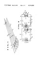
- FIG. 4 is a schematic view of an embodiment of an indexing means for moving a train of textile yarn buggies forward one buggy length.
- FIG. 1 of the drawings an embodiment of the present invention for lagging textile yarn on wheeled buggies is indicated generally by the numeral 10.
- Three storage lanes 11, 12 and 13 are provided for full textile yarn buggies and one buggy return lane 14 is provided for returning empty yarn buggies and a yarn spinning area.
- Buggy detecting means 15, 16, 17 and 18, which may comprise air switch pads (e.g. RBMA Controflex Roadswitch manufactured by Tape Switch Corporation of America, Farmingdale, New York) or other detecting devices, are positioned at the exits from lanes 11, 12, 13 and 14 respectively.
- Lane indicators 23, e.g. strips of colored tape or painted lines are provided to designate lanes 11, 12, 13 and 14 as such.
- Each of these indexing means is adapted to move a train of buggies forward one buggy length.
- FIG. 2 shows in outline two textile yarn buggies 30 and 31, each having a pair of swivel wheels 32 and 33 disposed respectively at the front and back thereof and a pair of fixed wheels 34 and 35 disposed respectively on the opposite sides thereof.
- a wishbone-shaped connecting hook 36 (see also FIG. 3) is pivotably mounted on a horizontal shaft 37 attached to the frame 38 at the front of buggies 30 and 31.
- Connecting hook 36 has a lead portion 39 and twin tail portions 40.
- Connecting hook 36 is adapted to be stored with its head portion 39 in an upright position against the buggy frame when not in use and to be flipped down such that its head portion 39 is in a horizontal position for use.
- the tail portions 40 of connecting hook 36 depend beneath the frame of the buggy to a point a few inches above the floor (see FIG. 3).
- a plate 41 is attached to the frame 42 at the rear of buggies 30 and 31.
- a hole 43 in plate 41 receives head portion 39 of connecting hook 36, head portion 39 being guided into hole 43 by a V-shaped guide 44 positioned on plate 41.
- a push bar 45 (see FIG. 3) is attached to the frame 38 at the front of each buggy and depends therefrom to a point a few inches above the floor.
- Push bar 45 is adapted to be engaged by a lug 46 of the indexing means shown in FIG. 4 and described hereinafter.
- Lug 46 of the indexing means is also adapted to engage one of the depending tail portions 40 of connecting hook 36 and to pivot connecting hook 36 about shaft 37 such that head portion 43 of connecting hook 36 is disconnected from hole 43 in plate 41 attached to frame 42 at the rear of the front buggy and is positioned in an upright position for storage.
- an indexing means of the type indicated by numerals 19, 20, 21 and 22 in FIG. 1, is designated generally by the numeral 19.
- a plurality of lugs 46 are mounted on a continuous chain 47.
- Chain 47 is supported at one end by a sprocket 48 on shaft 49 and is supported at the other end by a driven sprocket 50 on shaft 51, which is supported by a pillow block 52.
- Driven sprocket 50 is powered by a motor 53 through a gear reducer 54 and a pulley-belt system 55.
- Indexing means 19 is adapted to move at a low speed, e.g. 3 meters/minute, whenever motor 53 is started by a signal from a buggy detecting means, e.g. of the type designated by the numerals 15, 16, 17 and 18 in FIG. 1. After a suitable time delay, e.g. 15 or 20 seconds, the buggy detecting means signals the motor 53 to stop.
- buggy detecting means 15 sends a signal which starts motor 53 of indexing means 19 (see FIG. 4). Motor 53, through gear reducer 54, pulley-belt system 55 and driven sprocket 50, moves continuous chain 47 having lugs 46 mounted thereon at a low speed, e.g. 3 meters/minute. After a suitable time delay, e.g. 15 or 20 seconds, buggy detecting means 15 signals the motor 53 to stop.
- a spinning area operator connects (see FIG. 1) a full yarn buggy, which he has just completed filling with yarn packages, to the rear of the last buggy of the train of full buggies in lane 11 as described above for connecting the empty buggy to the train of empty buggies in lane 14.
- the spinning area operator goes to the exit from lane 14 and removes the front empty buggy therefrom.
- the buggy detecting means 18 sends a signal to indexing means 22 and the train of empty buggies is moved ahead one buggy length as described above for the indexing of the train of full buggies in lane 11.
- the carrier means for the lugs 46 of the indexing means 19 is the continuous chain 47 which is supported on the sprocket 48 and the driven sprocket 50, the driven sprocket 50 being powered by the motor 53 through the gear reducer 54 and the pulley-belt system 55.
- other carrier means may be provided for lugs 46.
- a single lug may be pivotably mounted on a carriage which is moved forward and back one buggy length by a double acting cable cylinder.
- the lug is adapted to remain upright and to engage tail portion 40 of connecting hook 36 and push bar 45 of a buggy as the carriage moves forward while the train is being indexed, and is adapted to pivot to a lay-flat position as the carriage moves back one buggy length to its starting position.
- twin lugs adapted to move in unison
- twin push bars would depend from the front frame of each buggy, and during indexing of the train of buggies, the twin lugs would engage both depending tail portions of the connecting hook and would also engage the twin push bars.
- the twin lugs may be carried by twin continuous chains mounted in parallel or the twin lugs may be mounted on the opposite sides of a carriage, which is moved forward and back one buggy length by a double acting cable cylinder, as described hereinbefore.
Landscapes
- Treatment Of Fiber Materials (AREA)
- Spinning Or Twisting Of Yarns (AREA)
Applications Claiming Priority (2)
| Application Number | Priority Date | Filing Date | Title |
|---|---|---|---|
| CA259,140A CA1046009A (fr) | 1976-08-16 | 1976-08-16 | Systeme de depose du file sur des chariots |
| CA259140 | 1976-08-16 |
Publications (1)
| Publication Number | Publication Date |
|---|---|
| US4144818A true US4144818A (en) | 1979-03-20 |
Family
ID=4106659
Family Applications (1)
| Application Number | Title | Priority Date | Filing Date |
|---|---|---|---|
| US05/811,984 Expired - Lifetime US4144818A (en) | 1976-08-16 | 1977-06-30 | Storage system for wheeled buggies and apparatus therefor |
Country Status (2)
| Country | Link |
|---|---|
| US (1) | US4144818A (fr) |
| CA (1) | CA1046009A (fr) |
Cited By (7)
| Publication number | Priority date | Publication date | Assignee | Title |
|---|---|---|---|---|
| US5090555A (en) * | 1989-04-28 | 1992-02-25 | Tsubakimoto Chain Co. | Conveyor of connected carriages |
| US5253745A (en) * | 1990-09-07 | 1993-10-19 | Oseney Limited | Conveying and storage systems |
| US6942088B1 (en) * | 2002-02-13 | 2005-09-13 | Intellect Ltd. | Conveyor system for transport of empty luggage carts from remote loading stations to multi-lane retrieval stations and method |
| US7178660B2 (en) | 2002-07-02 | 2007-02-20 | Jervis B. Webb Company | Workpiece transport system with independently driven platforms |
| US20070175732A1 (en) * | 2006-02-02 | 2007-08-02 | Dan Ellens | Skillet power system |
| US7404479B1 (en) * | 2007-02-22 | 2008-07-29 | Cnh America Llc | Towline cart engagement apparatus |
| US20160137418A1 (en) * | 2013-07-24 | 2016-05-19 | Eurofork S.R.L. | Automated warehouses |
Citations (11)
| Publication number | Priority date | Publication date | Assignee | Title |
|---|---|---|---|---|
| US1554049A (en) * | 1923-12-20 | 1925-09-15 | Hussong Dyeing Machine Company | Yarn truck |
| US2742863A (en) * | 1953-03-27 | 1956-04-24 | Link Belt Co | Car haul |
| US3297276A (en) * | 1964-12-09 | 1967-01-10 | Skufca Francisco | Transporter truck for industrial establishments |
| US3388806A (en) * | 1966-07-15 | 1968-06-18 | Cocker Machine & Foundry Compa | Textile yarn package truck |
| US3409141A (en) * | 1967-01-17 | 1968-11-05 | Cocker Machine & Foundry Compa | Textile yarn package truck |
| US3547282A (en) * | 1967-04-24 | 1970-12-15 | Corwn Zellerback Corp | Apparatus for transient handling and storing of articles |
| US3552693A (en) * | 1968-06-14 | 1971-01-05 | Hamel Gmbh Zwirnerei U Spinner | Twin-spool holder for twining and spinning machinery |
| US3568950A (en) * | 1969-03-06 | 1971-03-09 | Teijin Ltd | Bobbin truck for arranging transfer tail |
| US3738506A (en) * | 1970-11-06 | 1973-06-12 | A Cornford | Automatic storage system |
| US3773191A (en) * | 1970-12-02 | 1973-11-20 | Teijin Ltd | Method of and apparatus for arranging creels of drawing machines |
| US3927773A (en) * | 1972-06-19 | 1975-12-23 | Thomas John Robert Bright | Load storage system and apparatus therefor |
-
1976
- 1976-08-16 CA CA259,140A patent/CA1046009A/fr not_active Expired
-
1977
- 1977-06-30 US US05/811,984 patent/US4144818A/en not_active Expired - Lifetime
Patent Citations (11)
| Publication number | Priority date | Publication date | Assignee | Title |
|---|---|---|---|---|
| US1554049A (en) * | 1923-12-20 | 1925-09-15 | Hussong Dyeing Machine Company | Yarn truck |
| US2742863A (en) * | 1953-03-27 | 1956-04-24 | Link Belt Co | Car haul |
| US3297276A (en) * | 1964-12-09 | 1967-01-10 | Skufca Francisco | Transporter truck for industrial establishments |
| US3388806A (en) * | 1966-07-15 | 1968-06-18 | Cocker Machine & Foundry Compa | Textile yarn package truck |
| US3409141A (en) * | 1967-01-17 | 1968-11-05 | Cocker Machine & Foundry Compa | Textile yarn package truck |
| US3547282A (en) * | 1967-04-24 | 1970-12-15 | Corwn Zellerback Corp | Apparatus for transient handling and storing of articles |
| US3552693A (en) * | 1968-06-14 | 1971-01-05 | Hamel Gmbh Zwirnerei U Spinner | Twin-spool holder for twining and spinning machinery |
| US3568950A (en) * | 1969-03-06 | 1971-03-09 | Teijin Ltd | Bobbin truck for arranging transfer tail |
| US3738506A (en) * | 1970-11-06 | 1973-06-12 | A Cornford | Automatic storage system |
| US3773191A (en) * | 1970-12-02 | 1973-11-20 | Teijin Ltd | Method of and apparatus for arranging creels of drawing machines |
| US3927773A (en) * | 1972-06-19 | 1975-12-23 | Thomas John Robert Bright | Load storage system and apparatus therefor |
Cited By (10)
| Publication number | Priority date | Publication date | Assignee | Title |
|---|---|---|---|---|
| US5090555A (en) * | 1989-04-28 | 1992-02-25 | Tsubakimoto Chain Co. | Conveyor of connected carriages |
| US5253745A (en) * | 1990-09-07 | 1993-10-19 | Oseney Limited | Conveying and storage systems |
| US5320210A (en) * | 1990-09-07 | 1994-06-14 | Oseney Limited | Conveying and storage systems |
| US6942088B1 (en) * | 2002-02-13 | 2005-09-13 | Intellect Ltd. | Conveyor system for transport of empty luggage carts from remote loading stations to multi-lane retrieval stations and method |
| US7178660B2 (en) | 2002-07-02 | 2007-02-20 | Jervis B. Webb Company | Workpiece transport system with independently driven platforms |
| US20070175732A1 (en) * | 2006-02-02 | 2007-08-02 | Dan Ellens | Skillet power system |
| US7306089B2 (en) | 2006-02-02 | 2007-12-11 | Jervis B. Webb Company | Skillet power system |
| US7404479B1 (en) * | 2007-02-22 | 2008-07-29 | Cnh America Llc | Towline cart engagement apparatus |
| US20160137418A1 (en) * | 2013-07-24 | 2016-05-19 | Eurofork S.R.L. | Automated warehouses |
| US9630774B2 (en) * | 2013-07-24 | 2017-04-25 | Eurofork S.R.L. | Automated warehouses |
Also Published As
| Publication number | Publication date |
|---|---|
| CA1046009A (fr) | 1979-01-09 |
Similar Documents
| Publication | Publication Date | Title |
|---|---|---|
| US4144818A (en) | Storage system for wheeled buggies and apparatus therefor | |
| US2022186A (en) | Tractor-trailer system | |
| AU675241B2 (en) | Process for transferring goods load units on or from a train and device for implementing the process | |
| US4440090A (en) | Storage arrangement for truck conveyor trolleys | |
| JPH0723567B2 (ja) | ボビン運搬貯蔵方法及び装置 | |
| US3782568A (en) | Spare tire carrier | |
| CN111688644A (zh) | 一种隧道洗车机传送系统 | |
| US3404636A (en) | Apparatus and method for final assembly of automotive vehicles | |
| JP2762179B2 (ja) | 搬送台車の自動搬送装置 | |
| US4527611A (en) | Permanent mold casting systems | |
| US3045609A (en) | Trolley transfer means | |
| JPH03249022A (ja) | 荷積み方法 | |
| US2987011A (en) | Conveyor interchange | |
| JP3136532B2 (ja) | 自動車等組立ラインの部品供給方法 | |
| CN209522201U (zh) | 一种夹具切换小车 | |
| JPH0344974B2 (fr) | ||
| JPH09142307A (ja) | 運搬用台車 | |
| JPH05248194A (ja) | トンネル覆工用セグメント供給装置 | |
| JP3366923B2 (ja) | 搬送装置の切離しゾーンにおける台車走行速度制御方法 | |
| JPH01317882A (ja) | 自走体使用の搬送設備 | |
| JPH0474252B2 (fr) | ||
| JPS6245964Y2 (fr) | ||
| JP3274322B2 (ja) | 結束パイプ搬送用コンベア装置 | |
| JPS6334069B2 (fr) | ||
| SU701883A1 (ru) | Подвесной толкающий конвейер |