US20180098675A1 - Robotic Vacuum Cleaner - Google Patents
Robotic Vacuum Cleaner Download PDFInfo
- Publication number
- US20180098675A1 US20180098675A1 US15/542,622 US201515542622A US2018098675A1 US 20180098675 A1 US20180098675 A1 US 20180098675A1 US 201515542622 A US201515542622 A US 201515542622A US 2018098675 A1 US2018098675 A1 US 2018098675A1
- Authority
- US
- United States
- Prior art keywords
- vacuum cleaner
- floor nozzle
- robotic vacuum
- base
- cleaner according
- Prior art date
- Legal status (The legal status is an assumption and is not a legal conclusion. Google has not performed a legal analysis and makes no representation as to the accuracy of the status listed.)
- Abandoned
Links
Images

Classifications
-
- A—HUMAN NECESSITIES
- A47—FURNITURE; DOMESTIC ARTICLES OR APPLIANCES; COFFEE MILLS; SPICE MILLS; SUCTION CLEANERS IN GENERAL
- A47L—DOMESTIC WASHING OR CLEANING; SUCTION CLEANERS IN GENERAL
- A47L9/00—Details or accessories of suction cleaners, e.g. mechanical means for controlling the suction or for effecting pulsating action; Storing devices specially adapted to suction cleaners or parts thereof; Carrying-vehicles specially adapted for suction cleaners
- A47L9/02—Nozzles
- A47L9/04—Nozzles with driven brushes or agitators
- A47L9/0494—Height adjustment of dust-loosening tools
-
- A—HUMAN NECESSITIES
- A47—FURNITURE; DOMESTIC ARTICLES OR APPLIANCES; COFFEE MILLS; SPICE MILLS; SUCTION CLEANERS IN GENERAL
- A47L—DOMESTIC WASHING OR CLEANING; SUCTION CLEANERS IN GENERAL
- A47L5/00—Structural features of suction cleaners
- A47L5/12—Structural features of suction cleaners with power-driven air-pumps or air-compressors, e.g. driven by motor vehicle engine vacuum
- A47L5/22—Structural features of suction cleaners with power-driven air-pumps or air-compressors, e.g. driven by motor vehicle engine vacuum with rotary fans
-
- A—HUMAN NECESSITIES
- A47—FURNITURE; DOMESTIC ARTICLES OR APPLIANCES; COFFEE MILLS; SPICE MILLS; SUCTION CLEANERS IN GENERAL
- A47L—DOMESTIC WASHING OR CLEANING; SUCTION CLEANERS IN GENERAL
- A47L9/00—Details or accessories of suction cleaners, e.g. mechanical means for controlling the suction or for effecting pulsating action; Storing devices specially adapted to suction cleaners or parts thereof; Carrying-vehicles specially adapted for suction cleaners
- A47L9/009—Carrying-vehicles; Arrangements of trollies or wheels; Means for avoiding mechanical obstacles
-
- A—HUMAN NECESSITIES
- A47—FURNITURE; DOMESTIC ARTICLES OR APPLIANCES; COFFEE MILLS; SPICE MILLS; SUCTION CLEANERS IN GENERAL
- A47L—DOMESTIC WASHING OR CLEANING; SUCTION CLEANERS IN GENERAL
- A47L9/00—Details or accessories of suction cleaners, e.g. mechanical means for controlling the suction or for effecting pulsating action; Storing devices specially adapted to suction cleaners or parts thereof; Carrying-vehicles specially adapted for suction cleaners
- A47L9/02—Nozzles
- A47L9/04—Nozzles with driven brushes or agitators
- A47L9/0461—Dust-loosening tools, e.g. agitators, brushes
- A47L9/0466—Rotating tools
- A47L9/0477—Rolls
-
- A—HUMAN NECESSITIES
- A47—FURNITURE; DOMESTIC ARTICLES OR APPLIANCES; COFFEE MILLS; SPICE MILLS; SUCTION CLEANERS IN GENERAL
- A47L—DOMESTIC WASHING OR CLEANING; SUCTION CLEANERS IN GENERAL
- A47L9/00—Details or accessories of suction cleaners, e.g. mechanical means for controlling the suction or for effecting pulsating action; Storing devices specially adapted to suction cleaners or parts thereof; Carrying-vehicles specially adapted for suction cleaners
- A47L9/10—Filters; Dust separators; Dust removal; Automatic exchange of filters
- A47L9/14—Bags or the like; Rigid filtering receptacles; Attachment of, or closures for, bags or receptacles
- A47L9/1427—Means for mounting or attaching bags or filtering receptacles in suction cleaners; Adapters
- A47L9/1436—Connecting plates, e.g. collars, end closures
- A47L9/1445—Connecting plates, e.g. collars, end closures with closure means
-
- A—HUMAN NECESSITIES
- A47—FURNITURE; DOMESTIC ARTICLES OR APPLIANCES; COFFEE MILLS; SPICE MILLS; SUCTION CLEANERS IN GENERAL
- A47L—DOMESTIC WASHING OR CLEANING; SUCTION CLEANERS IN GENERAL
- A47L9/00—Details or accessories of suction cleaners, e.g. mechanical means for controlling the suction or for effecting pulsating action; Storing devices specially adapted to suction cleaners or parts thereof; Carrying-vehicles specially adapted for suction cleaners
- A47L9/28—Installation of the electric equipment, e.g. adaptation or attachment to the suction cleaner; Controlling suction cleaners by electric means
- A47L9/2805—Parameters or conditions being sensed
- A47L9/2821—Pressure, vacuum level or airflow
-
- A—HUMAN NECESSITIES
- A47—FURNITURE; DOMESTIC ARTICLES OR APPLIANCES; COFFEE MILLS; SPICE MILLS; SUCTION CLEANERS IN GENERAL
- A47L—DOMESTIC WASHING OR CLEANING; SUCTION CLEANERS IN GENERAL
- A47L9/00—Details or accessories of suction cleaners, e.g. mechanical means for controlling the suction or for effecting pulsating action; Storing devices specially adapted to suction cleaners or parts thereof; Carrying-vehicles specially adapted for suction cleaners
- A47L9/28—Installation of the electric equipment, e.g. adaptation or attachment to the suction cleaner; Controlling suction cleaners by electric means
- A47L9/2836—Installation of the electric equipment, e.g. adaptation or attachment to the suction cleaner; Controlling suction cleaners by electric means characterised by the parts which are controlled
- A47L9/2842—Suction motors or blowers
-
- A—HUMAN NECESSITIES
- A47—FURNITURE; DOMESTIC ARTICLES OR APPLIANCES; COFFEE MILLS; SPICE MILLS; SUCTION CLEANERS IN GENERAL
- A47L—DOMESTIC WASHING OR CLEANING; SUCTION CLEANERS IN GENERAL
- A47L9/00—Details or accessories of suction cleaners, e.g. mechanical means for controlling the suction or for effecting pulsating action; Storing devices specially adapted to suction cleaners or parts thereof; Carrying-vehicles specially adapted for suction cleaners
- A47L9/28—Installation of the electric equipment, e.g. adaptation or attachment to the suction cleaner; Controlling suction cleaners by electric means
- A47L9/2836—Installation of the electric equipment, e.g. adaptation or attachment to the suction cleaner; Controlling suction cleaners by electric means characterised by the parts which are controlled
- A47L9/2852—Elements for displacement of the vacuum cleaner or the accessories therefor, e.g. wheels, casters or nozzles
-
- A—HUMAN NECESSITIES
- A47—FURNITURE; DOMESTIC ARTICLES OR APPLIANCES; COFFEE MILLS; SPICE MILLS; SUCTION CLEANERS IN GENERAL
- A47L—DOMESTIC WASHING OR CLEANING; SUCTION CLEANERS IN GENERAL
- A47L9/00—Details or accessories of suction cleaners, e.g. mechanical means for controlling the suction or for effecting pulsating action; Storing devices specially adapted to suction cleaners or parts thereof; Carrying-vehicles specially adapted for suction cleaners
- A47L9/28—Installation of the electric equipment, e.g. adaptation or attachment to the suction cleaner; Controlling suction cleaners by electric means
- A47L9/2868—Arrangements for power supply of vacuum cleaners or the accessories thereof
- A47L9/2873—Docking units or charging stations
-
- A—HUMAN NECESSITIES
- A47—FURNITURE; DOMESTIC ARTICLES OR APPLIANCES; COFFEE MILLS; SPICE MILLS; SUCTION CLEANERS IN GENERAL
- A47L—DOMESTIC WASHING OR CLEANING; SUCTION CLEANERS IN GENERAL
- A47L9/00—Details or accessories of suction cleaners, e.g. mechanical means for controlling the suction or for effecting pulsating action; Storing devices specially adapted to suction cleaners or parts thereof; Carrying-vehicles specially adapted for suction cleaners
- A47L9/28—Installation of the electric equipment, e.g. adaptation or attachment to the suction cleaner; Controlling suction cleaners by electric means
- A47L9/2868—Arrangements for power supply of vacuum cleaners or the accessories thereof
- A47L9/2884—Details of arrangements of batteries or their installation
-
- A—HUMAN NECESSITIES
- A47—FURNITURE; DOMESTIC ARTICLES OR APPLIANCES; COFFEE MILLS; SPICE MILLS; SUCTION CLEANERS IN GENERAL
- A47L—DOMESTIC WASHING OR CLEANING; SUCTION CLEANERS IN GENERAL
- A47L9/00—Details or accessories of suction cleaners, e.g. mechanical means for controlling the suction or for effecting pulsating action; Storing devices specially adapted to suction cleaners or parts thereof; Carrying-vehicles specially adapted for suction cleaners
- A47L9/28—Installation of the electric equipment, e.g. adaptation or attachment to the suction cleaner; Controlling suction cleaners by electric means
- A47L9/2894—Details related to signal transmission in suction cleaners
-
- A—HUMAN NECESSITIES
- A47—FURNITURE; DOMESTIC ARTICLES OR APPLIANCES; COFFEE MILLS; SPICE MILLS; SUCTION CLEANERS IN GENERAL
- A47L—DOMESTIC WASHING OR CLEANING; SUCTION CLEANERS IN GENERAL
- A47L2201/00—Robotic cleaning machines, i.e. with automatic control of the travelling movement or the cleaning operation
- A47L2201/02—Docking stations; Docking operations
- A47L2201/022—Recharging of batteries
-
- A—HUMAN NECESSITIES
- A47—FURNITURE; DOMESTIC ARTICLES OR APPLIANCES; COFFEE MILLS; SPICE MILLS; SUCTION CLEANERS IN GENERAL
- A47L—DOMESTIC WASHING OR CLEANING; SUCTION CLEANERS IN GENERAL
- A47L2201/00—Robotic cleaning machines, i.e. with automatic control of the travelling movement or the cleaning operation
- A47L2201/04—Automatic control of the travelling movement; Automatic obstacle detection
-
- A—HUMAN NECESSITIES
- A47—FURNITURE; DOMESTIC ARTICLES OR APPLIANCES; COFFEE MILLS; SPICE MILLS; SUCTION CLEANERS IN GENERAL
- A47L—DOMESTIC WASHING OR CLEANING; SUCTION CLEANERS IN GENERAL
- A47L2201/00—Robotic cleaning machines, i.e. with automatic control of the travelling movement or the cleaning operation
- A47L2201/06—Control of the cleaning action for autonomous devices; Automatic detection of the surface condition before, during or after cleaning
Definitions
- the invention relates to a robotic vacuum cleaner.
- Conventional vacuum cleaners are operated by a user who moves the vacuum cleaner, and in particular the floor nozzle through which dust is suctioned, across the surface to be cleaned.
- Conventional floor vacuum cleaners there comprise, for example, a housing which is mounted on rollers and/or runners.
- a dust collection container is arranged in the housing and contains a filter bag.
- a floor nozzle is via a suction tube and a suction hose connected to the dust collection chamber.
- a motorized fan unit is further arranged in the housing and creates a negative pressure in the dust collection container. In the air flow direction, the motorized fan unit is therefore arranged downstream of the floor nozzle, the suction tube, the suction hose, and the dust collection container or the filter bag, respectively. Since cleaned air passes though such motorized fan units, they are sometimes referred to as clean air motors.
- Such dirty air or fouled air motor fans are also referred to as a “dirty air motor” or “direct air motor”.
- the use of such dirty air motors is also described in documents GB 554 177, U.S. Pat. No. 4,644,606, U.S. Pat. No. 4,519,112, US 2002/0159897, U.S. Pat. No. 5,573,369, US 2003/0202890 or U.S. Pat. No. 6,171,054.
- robotic vacuum cleaners have also gained popularity. Such robotic vacuum cleaners no longer have to be guided by a user over the surface to be cleaned; they instead drive autonomously across the floor. Examples of such robotic vacuum cleaners are known, for example, from EP 2 741 483, DE 10 2013 100 192 and US 2007/0272463.
- This robotic vacuum cleaner is structured in two parts and comprises a container or fan module and a cleaning module which is connected to the fan module via a hose.
- the object underlying the invention is to provide an improved robotic vacuum cleaner.
- a robotic vacuum cleaner comprising a base mounted on wheels, a dust collector, and a floor nozzle arranged on the base for collecting an air flow into the robotic vacuum cleaner, the floor nozzle being adjustable in height with respect to the base.
- Adjustability in height of the floor nozzle allows the robotic vacuum cleaner to overcome floor unevenness, in particular elevations. If, for example, the robotic vacuum cleaner when coming from a hard floor, with its floor nozzle bumps against a carpet edge, then the floor nozzle can be raised relative to the base so that the robotic vacuum cleaner can then push itself onto the carpet.
- the base itself can be formed to not be adjustable in height.
- the floor nozzle is fluidically connected to the base and/or to the dust collector, for example via a hose and/or tube connection.
- the air flow (for example, suctioned in) flows through the floor nozzle into the robotic vacuum cleaner and therefore subsequently into the dust collector connected fluidically to the floor nozzle.
- the floor nozzle can in particular be positioned at an inclination with respect to the base.
- the base can be oriented parallel to the surface to be cleaned.
- the inclined position can be such that the distance between the floor nozzle and a surface to be cleaned increases starting from the base.
- the robotic vacuum cleaner can push itself onto an elevation. If the floor nozzle there at least partly rests on the floor (the elevation), then the base can by a (forward) motion of the robotic vacuum cleaner also be raised.
- the floor nozzle can be arranged on or attached to the base in different ways.
- the floor nozzle can be pivotally hinged on the base.
- height adjustment of the floor nozzle is effected by pivoting about a pivot axis. This makes it possible to bring the floor nozzle into a position that is inclined relative to the base.
- the floor nozzle In an initial position, the floor nozzle can be oriented parallel to the base and/or parallel to a surface to be cleaned.
- the floor nozzle can be arranged on one side of the base. It can in particular be arranged in front of the base (in the direction of the intended direction of movement).
- the base can comprise a housing.
- the floor nozzle can be arranged on or attached to the housing. It can, for example, be pivotally hinged to the housing of the base.
- the floor nozzle can be arranged on one side of the housing, in particular in front of the housing (viewed in the direction of the intended direction of movement).
- the floor nozzle can be lockable in a fixed position or a plurality of fixed positions with respect to the base.
- the floor nozzle can thereby be fixed in a desired position relative to the base, which allows for the adjustment of desired pressure conditions at, under and/or in the floor nozzle as well as for pushing the robotic vacuum cleaner onto an unevenness or floor elevation.
- this can be, in particular, one or several pivoting or angular positions.
- the floor nozzle can be arranged freely movable with respect to the base.
- the robotic vacuum cleaners described above can comprise a distance and/or obstacle sensor.
- the distance and/or obstacle sensor can be an optical sensor or a pressure sensor.
- the distance and/or obstacle sensor can be arranged on the base or on the floor nozzle.
- a distance sensor or obstacle sensor is used to detect unevenness, in particular elevations.
- the robotic vacuum cleaners described above can comprise a stepping motor or a servo motor for height adjustment of the floor nozzle with respect to the base.
- a stepping motor or a servo motor for example, the floor nozzle can be moved (rotated) about a pivot axis.
- the above-described robotic vacuum cleaners can comprise a brush roller arranged in or on the floor nozzle.
- the brush roller (sometimes referred to as a beating and/or rotation brush) can be driven electro-motorically.
- the floor nozzle can comprise a floor plate with a base surface which, during operation of the robotic vacuum cleaner, faces the surface to be cleaned, where the floor plate comprises an air flow channel in the base surface through which air to be cleaned enters the floor nozzle.
- the floor plate is also referred to as a nozzle sole.
- the air flow channel is also referred to as a suction slot, nozzle opening, suction mouth or suction channel.
- the floor plate can with its base surface during operation of the robotic vacuum cleaner rest in an initial position on the surface to be cleaned (the floor) or be spaced apart therefrom.
- the base surface can in particular be arranged parallel to the surface to be cleaned.
- the floor nozzle can comprise a bristle strip with which, in the event of a spacing, the air flow through the slot between the surface to be cleaned and the floor plate can be adjusted.
- the air flow channel can parallel to the base surface have a straight, i.e. not curved, or a curved shape. It can have two parallel transverse sides, formed in particular to be rectilinear. In particular, it can have a rectangular shape or base surface.
- the longitudinal direction is meant to be the direction in which the air flow channel has its minimal extension parallel to the base surface of the floor nozzle;
- the transverse direction is perpendicular thereto (i.e., in the direction of maximum extension of the air flow channel) and also parallel to the base surface.
- the longitudinal sides are therefore the sides along or parallel to the direction of minimum extension, and the transverse sides are the sides along the direction of maximum extension in the plane of the base surface.
- the floor nozzle can also comprise several air flow channels. In the case of several air flow channels, they can have the same shape or different shapes.
- the floor nozzle can comprise a drive device in order to drive at least one of the wheels.
- the wheels can be designed for direct contact with the floor. Alternatively, they can be designed as drive wheels for a crawler chain. In the latter case, the crawler chain will during operation of the robotic vacuum cleaner directly contact the ground for moving the robotic vacuum cleaner.
- One of the wheels, several or all wheels can be omnidirectional wheels. This is particularly useful with direct contact of the wheels to the floor during operation of the robotic vacuum cleaner.
- the floor nozzle can comprise a rotation device for rotating the air flow channel about an axis perpendicular to the base surface.
- a rotation device allows for advantageously aligning the air flow channel through which dirt and dust to be absorbed enters the floor nozzle. This increases the suction efficiency of the robotic vacuum cleaner since, in particular, the floor surface processed by the floor nozzle is optimized due to the air flow channel.
- the rotation device can in particular be designed in the manner described in European patent application No. 15 151 741.4.
- Each omnidirectional wheel can on its circumference comprise a plurality of rotatably mounted rollers or roller bodies, respectively, these axes of which doe not extend parallel to the wheel axis (of the omnidirectional wheel).
- the axes of the rollers can in particular run or be oriented at an angle or transverse with respect to the wheel axis.
- An example of an omnidirectional wheel is a Mecanum wheel, which is described, inter alia, in U.S. Pat. No. 3,876,255.
- the robotic vacuum cleaners described above can comprise a control device for controlling height adjustment of the floor nozzle with respect to the base.
- the control device can in particular be designed to automatically control height adjustment of the floor nozzle with respect to the base.
- the control device can be configured to control a pivotal motion of the floor nozzle about a pivot axis.
- the control device can be adapted to control the above-mentioned stepping motor or the above-mentioned servo motor.
- the control device can be designed to control height adjustment in dependence of or as a function of signals or data from a distance and/or an obstacle sensor. If, for example, a distance and/or obstacle sensor detects unevenness or an elevation, then the control device can cause the floor nozzle to be raised with respect to the base. In an analogous manner, the control device can cause the floor nozzle to be lowered when a depression is detected.
- the robotic vacuum cleaners described above can comprise a pressure and/or airflow sensor for determining the pressure and/or the speed of the air suctioned in.
- the control device can be configured to control height adjustment of the floor nozzle in dependence of or as a function of data or signals from a pressure and/or air flow sensor. In this way, the suction and/or air flow conditions can be set in a desired manner in order to achieve an optimized suctioning result.
- the robotic vacuum cleaners described above can comprise a motorized fan unit for suctioning in an airflow through the floor nozzle.
- the motorized fan unit can be a dirty air motor or a clean air motor.
- the motorized fan unit can have an in particular single stage radial fan.
- the use of a motorized fan unit leads to particularly good cleaning or suctioning results.
- With a radial fan the air is suctioned in parallel or axially relative to the drive axis of the fan wheel and deflected by the rotation of the fan wheel, in particular by approximately 90°, and blown out radially.
- the floor nozzle comprises a suction opening for producing a fluidic connection to the motorized fan unit. This suction opening is in fluidic communication with the air flow channel.
- the motorized fan unit can be arranged between the floor nozzle and the dust collector unit such that an air flow suctioned in through the floor nozzle flows through the motorized fan unit into the dust collector assembly.
- a dirty air motor or direct air motor is thereby advantageously used in a robotic vacuum cleaner. Even with low motor power, a high volumetric flow can be obtained with the robotic vacuum cleaner according to the invention.
- the motorized fan unit can also be arranged fluidically downstream of the dust collector such that an air flow suctioned in through the floor nozzle flows through the dust collector into the motorized fan unit.
- a clean air motor is used.
- the robotic vacuum cleaners described above can comprise a floor nozzle module and a power supply module, where the floor nozzle module comprises the base mounted on wheels and the floor nozzle connected to the base.
- the power supply module is mounted on wheels and comprises a drive device for driving at least one of the wheels of the power supply module.
- the power supply module is connected to the floor nozzle module via a power supply cable in order to supply the floor nozzle module with power.
- the power supply for the floor nozzle module is provided by the (autonomously movable) power supply module. Therefore, the floor nozzle module need not comprise its own rechargeable batteries and can therefore be formed to be compact and have less weight. This improves movability of the floor nozzle module.
- the floor nozzle module can reach the surfaces to be suctioned even in confined conditions.
- the floor nozzle module and the power supply module are in this embodiment designed as individual or (spatially) separate units; they are each mounted separately on their own wheels.
- the floor nozzle module and the power supply modules are movable independently of one another. In particular, they can be connected to one another only by way of the power supply cable.
- the dust collector can be arranged on or in the floor nozzle module.
- the dust collector can be arranged on or in the power supply module.
- the floor nozzle module and the power supply module are connected to one another by way of a suction hose. Air suctioned in through this suction hose can be passed through the floor nozzle into the dust collector.
- the motorized fan unit can be arranged on or in the floor nozzle module. Alternatively, the motorized fan unit can be arranged on or in the power supply module.
- the motorized fan unit comprises a dirty air motor.
- one, several, or all the wheels of the power supply module can be omnidirectional wheels.
- the robotic vacuum cleaner can also comprise only one module.
- the dust collector and/or a power supply device can then be arranged on or in the wheel-mounted base. In this case, no separate power supply module is provided.
- the robotic vacuum cleaner can be a bag-type vacuum cleaner.
- a bag vacuum cleaner is a vacuum cleaner in which the suctioned dust is separated and collected in a vacuum cleaner filter bag.
- the robotic vacuum cleaner can in particular be a bag vacuum cleaner for disposable bags.
- the dust collector can comprise a vacuum cleaner filter bag, in particular with an area of at most 2000 cm 2 , in particular at most 1500 cm 2 .
- the dust collector can in particular consist of such a vacuum cleaner filter bag.
- the filter area of a vacuum cleaner filter bag designates the entire area of the filter material which is located between or within the edge seams (for example welding or adhesive seams). Any possibly side or surface folds that may be present also need to be considered.
- the area of the bag filling opening or inlet opening (including a seam surrounding this opening) is not part of the filter area.
- the vacuum cleaner filter bag can be a flat bag or have a block bottom shape.
- a flat bag is formed by two side walls made of filter material which are joined together (for example welded or glued) along their peripheral edges.
- the bag filling opening or inlet opening can be provided in one of the two side walls.
- the side faces or walls can each have a rectangular basic shape.
- Each side wall can comprise one or more layers of nonwoven and/or nonwoven fabric.
- the robotic vacuum cleaner in the form of a bag-type vacuum cleaner can comprise a vacuum cleaner filter bag, where the vacuum cleaner filter bag is designed in the form of a flat bag and/or a disposable bag.
- the bag wall of the vacuum cleaner filter bag can comprise one or more layers of a nonwoven and/or one or more layers of nonwoven fabric. It can in particular comprise a laminate of one or more layers of nonwoven and/or one or more layers of nonwoven fabric. Such a laminate is described, for example, in WO 2007/068444.
- nonwoven fabric is used within the meaning of standard DIN EN ISO 9092:2010.
- film and paper structures in particular filter paper, are there not regarded as being nonwoven fabric.
- “Nonwoven” is a structure made of fibers and/or continuous filaments or short fiber yarns shaped into a surface structure by some method (except interlacing of yarns such as woven fabric, knitwear, lace, or tufted fabric) but not bonded by some method. With a bonding process, a nonwoven turns into nonwoven fabric.
- the nonwoven or nonwoven fabric can be dry laid, wet laid or extruded.
- the suction devices described can comprise a holder for a vacuum cleaner filter bag.
- a holder for a vacuum cleaner filter bag can be arranged on, at or in the base and/or a housing of the robotic vacuum cleaner.
- the robotic vacuum cleaner can be a bagless vacuum cleaner, in particular with a blow-out filter with a filter area of at least 800 cm 2 .
- a bagless vacuum cleaner is a vacuum cleaner in which the suctioned dust is separated and collected without a vacuum cleaner filter bag.
- the dust collector can comprise an impact separator or a centrifugal separator or a cyclone separator, respectively.
- the robotic vacuum cleaners described above can comprise a navigation device for autonomously driving the robotic vacuum cleaner.
- the navigation device can be coupled to a control device for controlling height adjustment of the floor nozzle with respect to the base. In this way, height adjustment can also be controlled in dependence of or as a function of data or signals from the navigation device.
- the robotic vacuum cleaners described can comprise one or more devices for determining the location or position.
- the devices for determining the location can be, in particular, cameras, displacement sensors and/or distance sensors.
- the distance sensors can be based, for example, on sound waves or electromagnetic waves.
- the navigation device can be coupled to one or several devices for determining the location.
- navigation or autonomous driving can be performed in dependence of or as a function of data or signals from one or several devices for determining the location.
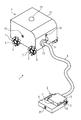
- FIG. 1 schematically shows a robotic vacuum cleaner composed of two modules
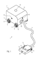
- FIG. 2 schematically shows a block circuit diagram of a robotic vacuum cleaner composed of two modules
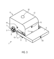
- FIG. 3 schematically shows an embodiment of a robotic vacuum cleaner com posed of one module.
- FIG. 1 is a schematic representation of a first embodiment of a robotic vacuum cleaner 1 .
- Robotic vacuum cleaner 1 illustrated comprises a power supply module 2 and a floor nozzle module 3 which is connected to power supply module 2 by way of a flexible suction hose 4 .
- Robotic vacuum cleaner 1 is in this embodiment therefore structured having two modules, where power supply module 2 and floor nozzle module 3 are separate units which are connected to one another only by way of suction hose 4 .
- Power supply module 2 is mounted on four wheels 5 , where each of these wheels is in the example shown designed as an omnidirectional wheel. In principle, however, conventional wheels can also be used instead of the omnidirectional wheels.
- Each omnidirectional wheel 5 has a plurality of rotatably mounted rollers 6 on its circumference.
- the rotational axes of rollers 6 are all not parallel to the wheel axis 7 of the respective omnidirectional wheel.
- the rotational axes of the rollers can assume an angle of 45° relative to the respective wheel axis.
- the surfaces of the rollers or roller bodies are curved or bent.
- Power supply module 2 comprises a drive device for driving wheels 5 of the power supply module.
- the drive device can comprise a separate drive unit, for example, in the form of an electric motor, for each wheel 5 so that each wheel 5 can be driven independently of the other wheels.
- Rollers 6 are rotatably mounted without a drive.
- power supply module 2 can be moved in any direction. If, for example, all four wheels 5 are moved at the same speed in the same direction of rotation, then the power supply module moves straight ahead. With a counter-rotating movement of the wheels on one side, a lateral movement or displacement can be achieved.
- the power supply module can also comprise fewer or more than four wheels. Not all wheels there need to be designed as omnidirectional wheels. An example with three omnidirectional wheels is described in US 2007/0272463.
- Floor nozzle module 3 comprises a base 8 and a floor nozzle 9 arranged on this base 8 .
- Base 8 (and therefore also the entire floor nozzle module 3 ) is in the example shown mounted on four omnidirectional wheels 5 .
- These wheels are in the embodiment sized to be smaller than the wheels of power supply module 2 .
- floor nozzle 3 also comprises a drive device for wheels 5 .
- the drive device for each wheel comprises a single drive unit, for example, in the form of electric motors, in order to drive each wheel separately and independently of the other wheels. In this way, the floor nozzle can also be moved in any direction by suitably driving the wheels.
- conventional wheels can also be used instead of the omnidirectional wheels.
- the wheels can also be designed as drive wheels for a crawler chain so that the robotic vacuum cleaner is moved by a track drive.
- Floor nozzle 9 is pivotally hinged on base 8 via a pivot joint 10 . Due to this pivotal mounting, floor nozzle 9 is designed to be adjustable in height with respect to base 8 , it can be tilted upwardly.
- Floor nozzle 9 comprises a floor plate with a base surface which, during operation of the robotic vacuum cleaner faces the floor, i.e. the surface to be suctioned.
- an air flow channel is incorporated parallel to the base surface through which the dirty air is suctioned in and via a flexible hose connection 11 passed into base 8 , from where it is passed through suction hose 4 to a dust collector in power supply module 2 .
- the floor nozzle can comprise a rotation device for rotating the air flow channel about an axis perpendicular to the base surface.
- power supply module 2 comprises a housing 12 on which a motorized fan unit 13 is arranged.
- a tube member 14 leads from motorized fan unit 13 into the interior of housing 12 to a vacuum cleaner filter bag disposed within the housing and forming a dust collector.
- the vacuum cleaner filter bag can be removably attached in the interior of housing 12 in a conventional manner, for example, by way of a holding plate.
- a continuous fluidic connection to the dust collector is therefore established by floor nozzle 3 , hose member 11 , base 8 , suction hose 4 , motorized fan unit 13 and tube member 14 .
- Motorized fan unit 13 is there arranged between suction hose 4 and the dust collector so that dirty air suctioned in through the floor nozzle flows through motorized fan unit 13 (in particular via tube member 14 ) into the vacuum cleaner filter bag arranged in the interior of housing 12 .
- Motorized fan unit 13 is therefore a dirty air motor. This is in particular a motorized fan unit comprising a radial fan.
- the motorized fan unit has a volumetric flow of more than 30 l/s (determined according to DIN EN 60312-1: 2014-01, with an aperture of 8) at an electrical input power of less than 450 W, a volumetric flow rate of more than 25 l/s at an electrical input power of less than 250, and a volumetric flow of more than 10 l/s at an electrical input power of less than 100 W.
- the fan diameter can be 60 mm to 160 mm.
- a motorized fan unit can be used, which is also used in Soniclean Upright vacuum cleaners (e.g. SONICLEAN VT PLUS).
- the motorized fan unit of the SONICLEAN VT PLUS was characterized according to DIN EN 60312-1: 2014-01 as explained above.
- the motorized fan unit was measured without the vacuum cleaner housing.
- the descriptions in section 7.3.7.1 apply.
- the table shows that high volumetric flows are obtained at low rotational speeds and low input power.
- power supply module 2 can also comprise a conventional clean air motor which is in the direction of air flow arranged downstream of the dust collector.
- the dirty air suctioned in would pass through suction hose 4 to power supply module 2 , enter its housing 12 and be passed into the dust collector, for example, in the form of a vacuum cleaner filter bag.
- Robotic vacuum cleaner 1 comprises a navigation device for driving power supply module 2 and floor nozzle module 3 in an autonomous manner.
- a correspondingly programmed microcontroller is arranged in housing 12 of power supply module 2 .
- the navigation device is connected to devices for determining the location. They include cameras 15 as well as distance sensors 16 .
- the distance sensors can be, for example, laser sensors.
- Navigation of the robotic vacuum cleaner occurs in a known manner, as described, for example, in WO 02/074150.
- the navigation device arranged in housing 12 controls both the drive unit of power supply module 2 as well as the drive unit of floor nozzle module 3 .
- a device for the latter for transmitting control signals from the navigation device in housing 12 of power supply module 2 to floor nozzle module 3 , in particular to the drive device of the floor nozzle module.
- wireless transmitters/receivers can respectively be arranged on the side of power supply module 2 and floor nozzle module 3 .
- a wired connection for transmitting control signals can also be provided along the suction hose.
- Floor nozzle module 3 can in a supporting manner also comprise one or more devices for determining the location. For example, path sensors and/or distance sensors can be provided on the floor nozzle module. In order to use the corresponding information for control and navigation, respective signals are transmitted from the floor nozzle module to the navigation device.
- the power supply for the robotic vacuum cleaner can be effected in a cabled or wireless manner.
- power supply module 2 can comprise rechargeable batteries which can be charged, for example, in a cabled or wireless (inductive) manner.
- robotic vacuum cleaner 1 can move, for example, autonomously to a charging station.
- Power supply for the floor nozzle module in particular its drive device, can be effected by way of a power supply cable in or along suction hose 4 . If the power supply to the drive device of the floor nozzle module is not exclusively effected by a power connection via suction hose 4 , then floor nozzle module 3 itself can also comprise rechargeable batteries.
- FIG. 2 is a schematic block diagram of a robotic vacuum cleaner 1 with a power supply module 2 and a floor nozzle module 3 .
- the drive device for wheels 5 of power supply unit 2 comprises, firstly, four drive units 17 in the form of electric motors and, secondly, a microcontroller 18 for controlling the electric motors.
- navigation device 19 which serves to autonomously drive the power supply module and the floor nozzle module.
- Navigation device 19 comprising a microcontroller is connected both to microcontroller 18 of the drive device as well as to a further microcontroller 20 which is part of the devices for determining the location. Data signals from different sensors and/or cameras are processed in microcontroller 20 and made available to navigation device 19 .
- Navigation device 19 is also connected to motorized fan unit 13 in order to control it.
- power supply or voltage supply is effected by way of a rechargeable battery 21 , which can be charged wirelessly or in a cabled manner.
- a rechargeable battery 21 which can be charged wirelessly or in a cabled manner.
- not all power supply connections are shown in the figure.
- Floor nozzle module 3 also comprises a drive device for its four wheels 5 , where the drive device, like in the case of power supply module 2 , comprises a microcontroller 15 and four electric motors 14 .
- the control signals for the drive device of floor nozzle module 3 originate from navigation device 19 which is arranged in power supply module 2 .
- the signals are transmitted via a communication line 22 which can be arranged, for example, in the wall of the suction hose. Alternatively, however, this signal transmission could also be effected wirelessly.
- Floor nozzle module 3 comprises a base 8 on which floor nozzle 9 is rotatably mounted by way of pivot joints 10 .
- a schematically indicated air flow channel 24 is arranged on the side of floor nozzle 9 facing the surface to be cleaned. Dirty air is suctioned in through air flow channel 24 and is via base 8 and suction hose 4 passed into the power supply module, more precisely its dust collector.
- floor nozzle 9 In a first position (initial position), floor nozzle 9 is aligned parallel to the base and to the (level) surface to be cleaned.
- the floor nozzle can in particular be locked in this position.
- a distance or obstacle sensor 25 is arranged on floor nozzle 9 . If, for example, unevenness, such as an elevation, is by way of this distance sensor or obstacle sensor 25 determined in the surface to be cleaned, then floor nozzle 9 can be adjusted in height relative to the surface to be cleaned or relative to base 8 , respectively.
- the unevenness can be, for example, a carpet edge or a door sill.
- Height adjustment of floor nozzle 9 is effected, for example, by pivoting the floor nozzle about the pivot joint with which floor nozzle 9 is connected to base 8 .
- rotational axes 10 can be designed as shafts which are each coupled to a stepping motor or a servo motor 26 .
- a control device 27 for controlling height adjustment of floor nozzle 9 relative to base 8 is provided in floor nozzle module 3 .
- the control device comprises a programmed microcontroller and is connected to sensor 25 . If an obstacle in the form of, for example, an elevation is detected by distance or obstacle sensor 25 , then a corresponding signal is sent to control device 27 which then drives electric motors 26 in such a way that the floor nozzle by way of a rotation pivots by a certain angle and is thereby raised. In this new position, the floor nozzle can then be locked by stopping (or blocking) electric motors 26 .
- floor nozzle module 3 Due to the raised floor nozzle 9 , floor nozzle module 3 is no longer blocked by the elevation because the latter fits underneath floor nozzle 9 .
- floor nozzle 9 in the course of the advance motion rests on or impacts such an elevation, then base 8 is due to the inclined position of floor nozzle 9 also lifted upwardly when the floor nozzle module is further advanced. In this way, floor nozzle module 3 pushes itself completely onto and over the elevation.
- Floor nozzle 9 can also be provided with a distance sensor on its underside, i.e. on the side facing the surface to be cleaned.
- This distance sensor can, for example, be arranged in the floor plate of floor nozzle 9 . With this distance sensor, the distance can be determined between the floor nozzle (its underside) and the surface to be cleaned. It can via the changes in the detected distance be ascertained whether or not the surface to be cleaned exhibits any unevenness.
- a depression in the surface to be cleaned is in this way detected (for example, the transition from a carpet to a hard floor), then the floor nozzle can again be lowered. In an analogous manner, it can be detected via a decreasing distance between the base surface of the floor nozzle and the surface to be cleaned whether an elevation is present and a corresponding upwardly motion of the floor nozzle can be initiated.
- Floor nozzle module 3 in particular floor nozzle 9 , can comprise an active (electro-motorically driven) brush roller or a passive (not electro-motorically driven) brush roller.
- the fan unit can also be arranged on, at or in the floor nozzle module.
- the dust collector can also be provided on the side of the floor nozzle module. A suction hose connection between the floor nozzle module and the power supply module is thereby rendered obsolete. In this case, only a power cable must be provided between the power supply module and the floor nozzle module. Alternatively, however, the dust collector can also be provided on the side of the power supply module.
- the robotic vacuum cleaner can also consist merely of one module, as shown schematically in FIG. 3 .
- floor nozzle 9 is via a rotational axis or shaft 10 likewise hinged to a base 8 which in this case comprises housing 12 .
- floor nozzle 9 can be adjusted in height relative to base 8 by way of pivoting about rotational axis 10 . In an initial position, floor nozzle 9 can be aligned parallel to a planar surface to be cleaned. Pivoting the floor nozzle leads to an oblique position.
- Floor nozzle 9 also in this embodiment on its underside (the side facing the surface to be cleaned) comprises an air flow channel through which dirty air is suctioned in and via a hose member 11 passed into housing 12 of base 8 , in the interior of which the dust collector is arranged, for example in the form of a vacuum cleaner filter bag or an impact separator.
Landscapes
- Engineering & Computer Science (AREA)
- Mechanical Engineering (AREA)
- Robotics (AREA)
- Electric Vacuum Cleaner (AREA)
- Nozzles For Electric Vacuum Cleaners (AREA)
- Electric Suction Cleaners (AREA)
Applications Claiming Priority (7)
| Application Number | Priority Date | Filing Date | Title |
|---|---|---|---|
| EP15151741.4 | 2014-01-20 | ||
| EP15151742.2A EP3047772B1 (de) | 2015-01-20 | 2015-01-20 | Staubsaugerroboter |
| EP15151741.4A EP3047771B1 (de) | 2015-01-20 | 2015-01-20 | Staubsaugerroboter |
| EP15151742.2 | 2015-01-20 | ||
| EP15162703.1A EP3047777B1 (de) | 2015-01-20 | 2015-04-08 | Staubsaugerroboter |
| EP15162703.1 | 2015-04-08 | ||
| PCT/EP2015/079469 WO2016116222A1 (de) | 2015-01-20 | 2015-12-11 | Staubsaugerroboter |
Publications (1)
| Publication Number | Publication Date |
|---|---|
| US20180098675A1 true US20180098675A1 (en) | 2018-04-12 |
Family
ID=52811054
Family Applications (2)
| Application Number | Title | Priority Date | Filing Date |
|---|---|---|---|
| US15/544,391 Expired - Fee Related US10470630B2 (en) | 2015-01-20 | 2015-12-11 | Vacuum cleaner robot |
| US15/542,622 Abandoned US20180098675A1 (en) | 2015-01-20 | 2015-12-11 | Robotic Vacuum Cleaner |
Family Applications Before (1)
| Application Number | Title | Priority Date | Filing Date |
|---|---|---|---|
| US15/544,391 Expired - Fee Related US10470630B2 (en) | 2015-01-20 | 2015-12-11 | Vacuum cleaner robot |
Country Status (9)
| Country | Link |
|---|---|
| US (2) | US10470630B2 (es) |
| EP (2) | EP3047783B1 (es) |
| CN (2) | CN107105949B (es) |
| AU (2) | AU2015378043C1 (es) |
| DK (2) | DK3047783T3 (es) |
| ES (2) | ES2769800T3 (es) |
| PL (2) | PL3047777T3 (es) |
| RU (2) | RU2674707C1 (es) |
| WO (2) | WO2016116218A1 (es) |
Cited By (2)
| Publication number | Priority date | Publication date | Assignee | Title |
|---|---|---|---|---|
| US11058270B2 (en) * | 2017-10-17 | 2021-07-13 | Maidbot, Inc. | Robotic apparatus, method, and applications |
| US11324375B2 (en) * | 2019-07-25 | 2022-05-10 | Jeffrey L. Koebrick | Automated floor maintenance system |
Families Citing this family (12)
| Publication number | Priority date | Publication date | Assignee | Title |
|---|---|---|---|---|
| US10518576B1 (en) | 2016-03-03 | 2019-12-31 | Al Incorporated | Expandable wheel |
| US11829148B1 (en) | 2016-03-03 | 2023-11-28 | AI Incorporated | Cleaning robot and operation thereof |
| US10214050B1 (en) | 2016-03-03 | 2019-02-26 | Al Incorporated | Robotic floor cleaning device with expandable wheels |
| KR102624560B1 (ko) * | 2017-01-31 | 2024-01-15 | 엘지전자 주식회사 | 청소기 |
| DE102017119574A1 (de) * | 2017-08-25 | 2019-02-28 | Kuka Deutschland Gmbh | Omnidirektional mobile Fahrplattform mit einer Arbeitsvorrichtung |
| JP7008610B2 (ja) | 2017-10-19 | 2022-01-25 | メイドボット インコーポレイテッド | 懸架装置、方法及び応用 |
| CA3116593A1 (en) * | 2018-10-22 | 2020-04-30 | Omachron Intellectual Property Inc. | Air treatment apparatus |
| TWI726551B (zh) * | 2018-12-24 | 2021-05-01 | 國立臺灣科技大學 | 清潔機器人 |
| CN110755003B (zh) * | 2019-11-01 | 2023-05-30 | 杭州埃欧珞机器人科技有限公司 | 一种基于涵道风扇的高空玻璃幕墙清洗装置 |
| EP3838095B1 (de) * | 2019-12-20 | 2022-08-31 | Eurofilters Holding N.V. | Halteplatte für einen staubsaugerfilterbeutel |
| DE102020204182A1 (de) | 2020-03-31 | 2021-09-30 | Volkswagen Aktiengesellschaft | Vorrichtung und Verfahren zur Reinigung von Oberflächen |
| CN116754100B (zh) * | 2023-08-15 | 2024-01-09 | 四川蜀旺新能源股份有限公司 | 用于光伏发电系统的电池模组温度监测设备 |
Citations (8)
| Publication number | Priority date | Publication date | Assignee | Title |
|---|---|---|---|---|
| US20020174506A1 (en) * | 2001-03-16 | 2002-11-28 | Wallach Bret A. | Autonomous canister vacuum cleaner |
| US6581239B1 (en) * | 1998-12-18 | 2003-06-24 | Dyson Limited | Cleaner head for a vacuum cleaner |
| US7200892B2 (en) * | 2003-07-24 | 2007-04-10 | Samsung Gwangju Electronics Co., Ltd. | Robot cleaner with adjustable brush |
| US7246405B2 (en) * | 2003-10-09 | 2007-07-24 | Jason Yan | Self-moving vacuum cleaner with moveable intake nozzle |
| US7599758B2 (en) * | 2003-09-19 | 2009-10-06 | Royal Appliance Mfg. Co. | Sensors and associated methods for controlling a vacuum cleaner |
| US20110239397A1 (en) * | 2007-08-21 | 2011-10-06 | Koninklijke Philips Electronics N.V. | Suction unit and autonomous vacuum cleaner |
| US20120152280A1 (en) * | 2010-12-18 | 2012-06-21 | Zenith Technologies, Llc | Touch Sensitive Display For Surface Cleaner |
| US20140068885A1 (en) * | 2012-09-10 | 2014-03-13 | Karcher North America, Inc. | Cable-actuated lift system |
Family Cites Families (61)
| Publication number | Priority date | Publication date | Assignee | Title |
|---|---|---|---|---|
| GB139892A (en) | 1919-03-12 | 1920-03-18 | Daniel Benson Replogle | Vacuum cleaning systems |
| FR768588A (fr) | 1933-05-31 | 1934-08-08 | Vorwerk & Co Elektrowerke Kg | Soufflerie, destinée en particulier aux aspirateurs de poussières |
| US2036056A (en) | 1934-06-07 | 1936-03-31 | Electric Vacuum Cleaner Co | Vacuum cleaner |
| BE413675A (es) | 1935-03-01 | |||
| NL68900C (es) | 1941-05-05 | |||
| US2482337A (en) | 1943-08-20 | 1949-09-20 | Eureka Williams Corp | Vacuum cleaner converter arrangement |
| US3876255A (en) | 1972-11-13 | 1975-04-08 | Ilon B E | Wheels for a course stable selfpropelling vehicle movable in any desired direction on the ground or some other base |
| US4519112A (en) | 1983-11-07 | 1985-05-28 | The National Super Service Company | Muffled vacuum cleaner |
| US4644606A (en) | 1985-04-08 | 1987-02-24 | Mcculloch Corporation | Lawn/garden blower/vacuum |
| CN1041672C (zh) * | 1993-06-07 | 1999-01-13 | 大宇电子株式会社 | 可使用高电压或低电压的电动机 |
| JP3207300B2 (ja) * | 1993-06-15 | 2001-09-10 | 日本輸送機株式会社 | 自動掃除機 |
| KR960008835B1 (ko) * | 1994-05-09 | 1996-07-05 | 엘지전자 주식회사 | 진공청소기의 회전형 상용 흡입구 |
| DE19505787C2 (de) * | 1995-02-20 | 1998-01-29 | Fedag Romanshorn Fa | Reinigungswalze für die Saugdüse eines Saugreinigungsgerätes |
| JPH0947413A (ja) * | 1995-08-08 | 1997-02-18 | Minolta Co Ltd | 清掃ロボット |
| JP4542628B2 (ja) | 1995-08-25 | 2010-09-15 | コーニンクレッカ フィリップス エレクトロニクス エヌ ヴィ | 電気ブラシの操作モードに依存する出力制御を有する真空掃除機 |
| US5573369A (en) | 1995-11-08 | 1996-11-12 | The Scott Fetzer Company | Impeller for vacuum cleaner with tapered blades |
| DE29803415U1 (de) | 1998-02-27 | 1998-06-25 | Kurz Gerhard | Bodendüse für Staubsauger |
| DE29812377U1 (de) | 1998-07-11 | 1998-10-15 | Wessel Werk Gmbh | Bodenhülse für Staubsauger |
| GB2344750B (en) * | 1998-12-18 | 2002-06-26 | Notetry Ltd | Vacuum cleaner |
| GB2344746A (en) * | 1998-12-18 | 2000-06-21 | Notetry Ltd | Vacuum cleaner wherein an alternative air inlet is selected by moving the separating apparatus |
| US6719830B2 (en) | 1999-05-21 | 2004-04-13 | Vortex Holding Company | Toroidal vortex vacuum cleaner centrifugal dust separator |
| US6171054B1 (en) | 1999-09-28 | 2001-01-09 | Royal Appliance Mfg. Co. | Impeller housing with reduced noise and improved airflow |
| CN1229068C (zh) | 2001-01-25 | 2005-11-30 | 皇家菲利浦电子有限公司 | 以摆线运动进行表面真空除尘的自动装置 |
| US6666660B2 (en) | 2001-04-27 | 2003-12-23 | The Hoover Company | Motor-fan assembly for a floor cleaning machine |
| US6719541B2 (en) | 2002-04-30 | 2004-04-13 | Northland/Scott Fetzer Company | Fan assembly with application to vacuum cleaners |
| US7113847B2 (en) | 2002-05-07 | 2006-09-26 | Royal Appliance Mfg. Co. | Robotic vacuum with removable portable vacuum and semi-automated environment mapping |
| FR2847791B1 (fr) | 2002-11-29 | 2006-05-05 | Claude Brenot | Appareil compact de nettoyage de sol |
| US20040200505A1 (en) * | 2003-03-14 | 2004-10-14 | Taylor Charles E. | Robot vac with retractable power cord |
| US20040211318A1 (en) | 2003-04-22 | 2004-10-28 | Oreck Holdings, Llc | Motor fan design for large debris ingestion |
| JP2005027829A (ja) * | 2003-07-11 | 2005-02-03 | Matsushita Electric Ind Co Ltd | 電気掃除機 |
| US7424766B2 (en) * | 2003-09-19 | 2008-09-16 | Royal Appliance Mfg. Co. | Sensors and associated methods for controlling a vacuum cleaner |
| KR100820743B1 (ko) * | 2003-10-21 | 2008-04-10 | 삼성전자주식회사 | 이동 로봇의 충전 장치 |
| KR100575668B1 (ko) * | 2003-12-30 | 2006-05-03 | 엘지전자 주식회사 | 로봇 청소기의 충전장치 |
| US20060020369A1 (en) * | 2004-03-11 | 2006-01-26 | Taylor Charles E | Robot vacuum cleaner |
| KR20060034851A (ko) * | 2004-10-20 | 2006-04-26 | 삼성광주전자 주식회사 | 유무선 겸용 진공청소기 |
| CA2498435A1 (en) | 2005-02-25 | 2006-08-25 | David B. Hiebert | Suction nozzle |
| US20060191098A1 (en) * | 2005-02-28 | 2006-08-31 | Hiebert David B | Suction nozzle |
| DE102005059214B4 (de) | 2005-12-12 | 2007-10-25 | Eurofilters N.V. | Filterbeutel für einen Staubsauger |
| WO2007093926A1 (en) | 2006-02-13 | 2007-08-23 | Koninklijke Philips Electronics N.V. | Robotic vacuum cleaning |
| KR20070101002A (ko) | 2006-04-10 | 2007-10-16 | 이바도 | 위성 방식의 청소로봇 시스템 |
| TWI293555B (en) | 2006-05-23 | 2008-02-21 | Ind Tech Res Inst | Omni-directional robot cleaner |
| KR100762095B1 (ko) * | 2006-06-29 | 2007-10-05 | 주식회사 로보스템 | 유 무선 자주식 청소기의 전원 공급을 위한 피동이동충전스테이션 |
| GB0615684D0 (en) * | 2006-08-08 | 2006-09-13 | Dyson Technology Ltd | An attachment for a cleaning appliance |
| DE102007040952A1 (de) | 2007-08-30 | 2009-03-05 | Miele & Cie. Kg | Upright-Staubsauger |
| DE102007057589B4 (de) * | 2007-11-28 | 2010-09-30 | BSH Bosch und Siemens Hausgeräte GmbH | Luft-Volumenstrom- und Schiebekraft-Regelungsvorrichtung |
| DE102008019976B4 (de) | 2008-04-21 | 2012-04-26 | Kuka Roboter Gmbh | Omnidirektional-Rad und Verfahren zur Montage von Rollkörpern eines Omnidirektional-Rades, sowie omnidirektional bewegliches Fahrwerk und dessen Verwendung |
| CN102046059A (zh) | 2008-08-08 | 2011-05-04 | 松下电器产业株式会社 | 吸尘器的控制装置及控制方法、吸尘器、吸尘器的控制程序以及集成电子电路 |
| DE102008046942A1 (de) | 2008-09-08 | 2010-03-11 | Alfred Kärcher Gmbh & Co. Kg | Staubsauger |
| US8234010B2 (en) * | 2010-02-16 | 2012-07-31 | Deere & Company | Tethered robot positioning |
| EP2420169A1 (en) | 2010-08-19 | 2012-02-22 | Koninklijke Philips Electronics N.V. | Cleaning device as well as a method to control a cleaning device |
| KR101637359B1 (ko) | 2010-08-20 | 2016-07-07 | 엘지전자 주식회사 | 청소기 |
| DK2672870T3 (en) * | 2011-02-11 | 2015-03-02 | Kaercher Gmbh & Co Kg Alfred | Process for cleaning a filter in a vacuum cleaner and vacuum cleaner for carrying out the process |
| DE102011083319A1 (de) | 2011-09-23 | 2013-03-28 | Robert Bosch Gmbh | Werkzeugzusatzgerät |
| TW201325531A (zh) * | 2011-12-29 | 2013-07-01 | qi-fang Huang | 吸塵嘴及具有該吸塵嘴之吸塵器套組 |
| US8960339B2 (en) | 2012-05-03 | 2015-02-24 | Helical Robotics, Llc | Mecanum wheel |
| EP3968621A3 (de) | 2012-12-05 | 2022-03-23 | Vorwerk & Co. Interholding GmbH | Verfahrbares bodenreinigungsgerät sowie verfahren zum betreiben eines solchen gerätes |
| CN203000795U (zh) * | 2012-12-25 | 2013-06-19 | 王玉玺 | 能用于清洁竖直面及天花板面并能跨越阴角作业的吸尘车 |
| DE102013100192A1 (de) | 2013-01-10 | 2014-07-10 | Miele & Cie. Kg | Selbstfahrender Roboter und Verfahren zur Abstandsbestimmung bei einem selbstfahrenden Roboter |
| DE202013008870U1 (de) | 2013-10-04 | 2013-10-29 | Kuka Roboter Gmbh | Omnidirektionales Fahrzeug mit Einzelradaufhängungen |
| PL2979742T3 (pl) | 2014-07-31 | 2023-01-30 | Eurofilters Holding N.V. | Uchwyt dla medium filtrującego |
| PL3047771T3 (pl) | 2015-01-20 | 2017-09-29 | Eurofilters Holding N.V. | Robot-odkurzacz |
-
2015
- 2015-04-08 EP EP15162704.9A patent/EP3047783B1/de active Active
- 2015-04-08 DK DK15162704.9T patent/DK3047783T3/en active
- 2015-04-08 ES ES15162703T patent/ES2769800T3/es active Active
- 2015-04-08 ES ES15162704.9T patent/ES2640394T3/es active Active
- 2015-04-08 DK DK15162703.1T patent/DK3047777T3/da active
- 2015-04-08 PL PL15162703T patent/PL3047777T3/pl unknown
- 2015-04-08 EP EP15162703.1A patent/EP3047777B1/de active Active
- 2015-04-08 PL PL15162704T patent/PL3047783T3/pl unknown
- 2015-12-11 US US15/544,391 patent/US10470630B2/en not_active Expired - Fee Related
- 2015-12-11 AU AU2015378043A patent/AU2015378043C1/en not_active Ceased
- 2015-12-11 RU RU2017118989A patent/RU2674707C1/ru active
- 2015-12-11 US US15/542,622 patent/US20180098675A1/en not_active Abandoned
- 2015-12-11 AU AU2015378047A patent/AU2015378047B2/en not_active Ceased
- 2015-12-11 WO PCT/EP2015/079461 patent/WO2016116218A1/de active Application Filing
- 2015-12-11 CN CN201580072229.9A patent/CN107105949B/zh not_active Expired - Fee Related
- 2015-12-11 CN CN201580074028.2A patent/CN107205596B/zh not_active Expired - Fee Related
- 2015-12-11 WO PCT/EP2015/079469 patent/WO2016116222A1/de active Application Filing
- 2015-12-11 RU RU2017118987A patent/RU2665457C1/ru active
Patent Citations (8)
| Publication number | Priority date | Publication date | Assignee | Title |
|---|---|---|---|---|
| US6581239B1 (en) * | 1998-12-18 | 2003-06-24 | Dyson Limited | Cleaner head for a vacuum cleaner |
| US20020174506A1 (en) * | 2001-03-16 | 2002-11-28 | Wallach Bret A. | Autonomous canister vacuum cleaner |
| US7200892B2 (en) * | 2003-07-24 | 2007-04-10 | Samsung Gwangju Electronics Co., Ltd. | Robot cleaner with adjustable brush |
| US7599758B2 (en) * | 2003-09-19 | 2009-10-06 | Royal Appliance Mfg. Co. | Sensors and associated methods for controlling a vacuum cleaner |
| US7246405B2 (en) * | 2003-10-09 | 2007-07-24 | Jason Yan | Self-moving vacuum cleaner with moveable intake nozzle |
| US20110239397A1 (en) * | 2007-08-21 | 2011-10-06 | Koninklijke Philips Electronics N.V. | Suction unit and autonomous vacuum cleaner |
| US20120152280A1 (en) * | 2010-12-18 | 2012-06-21 | Zenith Technologies, Llc | Touch Sensitive Display For Surface Cleaner |
| US20140068885A1 (en) * | 2012-09-10 | 2014-03-13 | Karcher North America, Inc. | Cable-actuated lift system |
Cited By (3)
| Publication number | Priority date | Publication date | Assignee | Title |
|---|---|---|---|---|
| US11058270B2 (en) * | 2017-10-17 | 2021-07-13 | Maidbot, Inc. | Robotic apparatus, method, and applications |
| US20210298547A1 (en) * | 2017-10-17 | 2021-09-30 | Maidbot, Inc. | Robotic Apparatus, Method, and Applications |
| US11324375B2 (en) * | 2019-07-25 | 2022-05-10 | Jeffrey L. Koebrick | Automated floor maintenance system |
Also Published As
| Publication number | Publication date |
|---|---|
| EP3047783B1 (de) | 2017-08-30 |
| ES2640394T3 (es) | 2017-11-02 |
| EP3047777B1 (de) | 2019-11-20 |
| CN107205596A (zh) | 2017-09-26 |
| AU2015378043C1 (en) | 2019-08-29 |
| AU2015378047B2 (en) | 2018-04-26 |
| US10470630B2 (en) | 2019-11-12 |
| AU2015378043A1 (en) | 2017-06-15 |
| DK3047783T3 (en) | 2017-10-23 |
| AU2015378043B2 (en) | 2018-11-08 |
| AU2015378047A1 (en) | 2017-06-15 |
| WO2016116222A1 (de) | 2016-07-28 |
| EP3047777A2 (de) | 2016-07-27 |
| CN107105949A (zh) | 2017-08-29 |
| CN107105949B (zh) | 2020-03-31 |
| CN107205596B (zh) | 2020-11-24 |
| RU2665457C1 (ru) | 2018-08-29 |
| PL3047783T3 (pl) | 2018-02-28 |
| DK3047777T3 (da) | 2020-01-20 |
| EP3047777A3 (de) | 2016-10-19 |
| EP3047783A1 (de) | 2016-07-27 |
| RU2674707C1 (ru) | 2018-12-12 |
| PL3047777T3 (pl) | 2020-05-18 |
| WO2016116218A1 (de) | 2016-07-28 |
| US20180020894A1 (en) | 2018-01-25 |
| ES2769800T3 (es) | 2020-06-29 |
Similar Documents
| Publication | Publication Date | Title |
|---|---|---|
| AU2015378047B2 (en) | Robotic vacuum cleaner | |
| AU2015378048A1 (en) | Vacuum cleaner robot | |
| US10674883B2 (en) | Vacuum cleaner robot | |
| US11330947B2 (en) | Cyclone type dust collector and cleaner having the same | |
| JP7117606B2 (ja) | 自律走行型掃除機 | |
| ES2758094T3 (es) | Aspiradora de funcionamiento autónomo, procedimiento de aspiración de polvo y uso de una aspiradora de funcionamiento autónomo | |
| JP5968100B2 (ja) | 自走式掃除機 | |
| US20220287523A1 (en) | Robotic vacuum cleaner and a method in a robotic vacuum cleaner | |
| JP7065275B2 (ja) | 自律走行型掃除機 | |
| JP7249496B2 (ja) | 自律走行型掃除機 | |
| KR20150075638A (ko) | 로봇 청소기 |
Legal Events
| Date | Code | Title | Description |
|---|---|---|---|
| AS | Assignment |
Owner name: EUROFILTERS HOLDING N.V., BELGIUM Free format text: ASSIGNMENT OF ASSIGNORS INTEREST;ASSIGNORS:SAUER, RALF;SCHULTINK, JAN;REEL/FRAME:043044/0529 Effective date: 20170606 |
|
| STPP | Information on status: patent application and granting procedure in general |
Free format text: DOCKETED NEW CASE - READY FOR EXAMINATION |
|
| STPP | Information on status: patent application and granting procedure in general |
Free format text: NON FINAL ACTION MAILED |
|
| STPP | Information on status: patent application and granting procedure in general |
Free format text: RESPONSE TO NON-FINAL OFFICE ACTION ENTERED AND FORWARDED TO EXAMINER |
|
| STPP | Information on status: patent application and granting procedure in general |
Free format text: FINAL REJECTION MAILED |
|
| STCB | Information on status: application discontinuation |
Free format text: ABANDONED -- FAILURE TO RESPOND TO AN OFFICE ACTION |