US20080297648A1 - Focus detection apparatus - Google Patents
Focus detection apparatus Download PDFInfo
- Publication number
- US20080297648A1 US20080297648A1 US12/120,513 US12051308A US2008297648A1 US 20080297648 A1 US20080297648 A1 US 20080297648A1 US 12051308 A US12051308 A US 12051308A US 2008297648 A1 US2008297648 A1 US 2008297648A1
- Authority
- US
- United States
- Prior art keywords
- section
- luminance information
- distance
- optical system
- focus detection
- Prior art date
- Legal status (The legal status is an assumption and is not a legal conclusion. Google has not performed a legal analysis and makes no representation as to the accuracy of the status listed.)
- Abandoned
Links
- 238000001514 detection method Methods 0.000 title claims abstract description 61
- 230000003287 optical effect Effects 0.000 claims abstract description 74
- 238000011156 evaluation Methods 0.000 claims abstract description 59
- 238000000605 extraction Methods 0.000 claims description 33
- 230000005540 biological transmission Effects 0.000 claims 3
- 230000009194 climbing Effects 0.000 description 33
- 238000000034 method Methods 0.000 description 33
- 238000012986 modification Methods 0.000 description 21
- 230000004048 modification Effects 0.000 description 21
- 238000012545 processing Methods 0.000 description 15
- 238000010586 diagram Methods 0.000 description 14
- 230000000875 corresponding effect Effects 0.000 description 10
- 230000011514 reflex Effects 0.000 description 9
- 230000000694 effects Effects 0.000 description 7
- 239000000284 extract Substances 0.000 description 5
- 230000008901 benefit Effects 0.000 description 4
- 230000008859 change Effects 0.000 description 2
- 230000002596 correlated effect Effects 0.000 description 2
- 230000014509 gene expression Effects 0.000 description 2
- 238000010606 normalization Methods 0.000 description 2
- 230000008569 process Effects 0.000 description 2
- 230000001276 controlling effect Effects 0.000 description 1
- 238000012937 correction Methods 0.000 description 1
- 238000007429 general method Methods 0.000 description 1
- 230000005693 optoelectronics Effects 0.000 description 1
Images


Classifications
-
- G—PHYSICS
- G03—PHOTOGRAPHY; CINEMATOGRAPHY; ANALOGOUS TECHNIQUES USING WAVES OTHER THAN OPTICAL WAVES; ELECTROGRAPHY; HOLOGRAPHY
- G03B—APPARATUS OR ARRANGEMENTS FOR TAKING PHOTOGRAPHS OR FOR PROJECTING OR VIEWING THEM; APPARATUS OR ARRANGEMENTS EMPLOYING ANALOGOUS TECHNIQUES USING WAVES OTHER THAN OPTICAL WAVES; ACCESSORIES THEREFOR
- G03B13/00—Viewfinders; Focusing aids for cameras; Means for focusing for cameras; Autofocus systems for cameras
- G03B13/32—Means for focusing
- G03B13/34—Power focusing
- G03B13/36—Autofocus systems
-
- G—PHYSICS
- G02—OPTICS
- G02B—OPTICAL ELEMENTS, SYSTEMS OR APPARATUS
- G02B7/00—Mountings, adjusting means, or light-tight connections, for optical elements
- G02B7/28—Systems for automatic generation of focusing signals
- G02B7/36—Systems for automatic generation of focusing signals using image sharpness techniques, e.g. image processing techniques for generating autofocus signals
- G02B7/38—Systems for automatic generation of focusing signals using image sharpness techniques, e.g. image processing techniques for generating autofocus signals measured at different points on the optical axis, e.g. focussing on two or more planes and comparing image data
-
- G—PHYSICS
- G03—PHOTOGRAPHY; CINEMATOGRAPHY; ANALOGOUS TECHNIQUES USING WAVES OTHER THAN OPTICAL WAVES; ELECTROGRAPHY; HOLOGRAPHY
- G03B—APPARATUS OR ARRANGEMENTS FOR TAKING PHOTOGRAPHS OR FOR PROJECTING OR VIEWING THEM; APPARATUS OR ARRANGEMENTS EMPLOYING ANALOGOUS TECHNIQUES USING WAVES OTHER THAN OPTICAL WAVES; ACCESSORIES THEREFOR
- G03B3/00—Focusing arrangements of general interest for cameras, projectors or printers
- G03B3/02—Focusing arrangements of general interest for cameras, projectors or printers moving lens along baseboard
-
- G—PHYSICS
- G03—PHOTOGRAPHY; CINEMATOGRAPHY; ANALOGOUS TECHNIQUES USING WAVES OTHER THAN OPTICAL WAVES; ELECTROGRAPHY; HOLOGRAPHY
- G03B—APPARATUS OR ARRANGEMENTS FOR TAKING PHOTOGRAPHS OR FOR PROJECTING OR VIEWING THEM; APPARATUS OR ARRANGEMENTS EMPLOYING ANALOGOUS TECHNIQUES USING WAVES OTHER THAN OPTICAL WAVES; ACCESSORIES THEREFOR
- G03B3/00—Focusing arrangements of general interest for cameras, projectors or printers
- G03B3/04—Focusing arrangements of general interest for cameras, projectors or printers adjusting position of image plane without moving lens
-
- H—ELECTRICITY
- H04—ELECTRIC COMMUNICATION TECHNIQUE
- H04N—PICTORIAL COMMUNICATION, e.g. TELEVISION
- H04N23/00—Cameras or camera modules comprising electronic image sensors; Control thereof
- H04N23/60—Control of cameras or camera modules
- H04N23/67—Focus control based on electronic image sensor signals
- H04N23/673—Focus control based on electronic image sensor signals based on contrast or high frequency components of image signals, e.g. hill climbing method
-
- G—PHYSICS
- G03—PHOTOGRAPHY; CINEMATOGRAPHY; ANALOGOUS TECHNIQUES USING WAVES OTHER THAN OPTICAL WAVES; ELECTROGRAPHY; HOLOGRAPHY
- G03B—APPARATUS OR ARRANGEMENTS FOR TAKING PHOTOGRAPHS OR FOR PROJECTING OR VIEWING THEM; APPARATUS OR ARRANGEMENTS EMPLOYING ANALOGOUS TECHNIQUES USING WAVES OTHER THAN OPTICAL WAVES; ACCESSORIES THEREFOR
- G03B2217/00—Details of cameras or camera bodies; Accessories therefor
- G03B2217/002—Details of arrangement of components in or on camera body
Definitions
- the present invention relates to a focus detection apparatus which specifies a focus position by using a light beam that has passed an optical system which forms an image of light from a subject on a predetermined position.
- the most general method as methods of detecting a focus by using an image acquisition device include technique called hill climbing method or contrast method.
- the focus detection method is widely used for electronic image acquisition apparatuses such as digital cameras.
- a plurality of images are acquired while a focus lens is driven in the optical axis direction, and an evaluation value of blurring is calculated for the acquired images.
- a contrast or a sum of high-frequency components of the image is used as the evaluation value. The greater value the evaluation value has, the more properly the focus is attained.
- the focus lens is driven with a minute distance in the near-point or far-point direction from the current position (hereinafter referred to as the “start point”) of the focus lens.
- the focus lens is driven in the far-point direction. If the evaluation value calculated during the driving is reduced in comparison with the evaluation value calculated at the start point, it means that the peak of the evaluation value exists in the direction (near-point direction) opposite to the driving direction. Therefore, in such a case, the focus lens is driven in the opposite direction.
- the evaluation value in the first driven direction increases. Therefore, in such a case, the peak of the evaluation value exists in the driving direction, and thus the focus lens is kept driven in the same direction.
- the focus detection method is called “Depth From Focus (hereinafter abbreviated to “DFF”) method”. Further, the method is also called “hill climbing method”, since control is performed to enhance the evaluation value and the peak of the evaluation value is estimated. As described above, the in-focus position coincides with the position of the focus lens where the evaluation value calculated by the “hill climbing method” is at the maximum.
- U.S. Pat. No. 4,965,840 discloses a focus detection method called “Depth From Defocus (hereinafter abbreviated to “DFD” method).
- DMD Depth From Defocus
- luminance information is obtained in two positions having different optical configurations focal length or aperture size.
- a plurality of images having different blurring degrees are computed, and thereby blurring parameter is calculated and the focus is determined.
- the blurring parameter is a representative value indicating the blurring state of the luminance information, and indicates a value correlated with the variance of the point spread function (PSF) of the optical system.
- PSF is a function indicating how the light beam spreads when an ideal point image passes an optical system.
- At least two luminance information items for focus determination are obtained from the same subject, the same region, and the same viewing direction, by changing at least one of image acquisition parameters which influence the blurring state of acquired images.
- the image acquisition parameters include the focus lens position, the aperture, and the focal length, etc. In this explanation, only the case is explained in which only the position of the focus lens is changed.
- the focus lens is moved to a predetermined first position and a second position, to change the optical path between the image acquisition section being a luminance information obtaining section and the subject, that is, to change the blurring state of the image formed on the image plane of the image acquisition section. Further, first luminance information is obtained in the first position, and second luminance information is obtained in the second position. These obtained luminance information items are subjected to low-pass filter to remove electric noises, image magnification correction to adjust the different magnifications between the first and second images, and normalization of luminance distribution. If necessary, a region of interest for focus evaluation is selected in the obtained luminance information. Selection is performed for one of the luminance information, and a corresponding region is selected for the other luminance information.
- a difference between the first luminance information and the second luminance information is calculated from two normalization processing results in the regions for which focus evaluation is to be performed. Further, the second-order differential of each of the first luminance information and the second luminance information is calculated, and a mean value of them is calculated. Then, the difference between the first luminance information and the second luminance information is divided by the mean value of the second order differentials of the luminance information items, and thereby a blurring parameter correlated with PSF variance corresponding to the first or second luminance information is calculated.
- the subject distance is obtained based on the relational expression between the PSF variance and the subject distance disclosed in U.S. Pat. No. 4,965,840.
- the relationship between the blurring parameter and the subject distance differs according to the structure and the state (zoom, aperture) of the lens. Further, the relationship between a certain subject distance and the focus lens position in which focus is attained for the subject distance, that is, the in-focus lens position is provided in advance by data of the lens system. Therefore, the relationship between the blurring parameter and the in-focus lens position to be controlled is determined by individual relational expressions or operational tables according to the lens system and the configuration of the lens.
- a focus detection apparatus which determines a focal position by using light beam that is passed an optical system which forms an image of light from a subject in a predetermined position, comprising:
- a luminance information acquiring section configured to acquire luminance information of the image formed by the optical system
- a blurring parameter operating section configured to calculate a blurring parameter corresponding to a distance from the optical system to the subject, based on two luminance information items which have different blurring degrees and are acquired by the luminance information acquiring section;
- a distance estimating section configured to estimate distance information corresponding to the distance from the optical system to the subject, based on the blurring parameter calculated by using the blurring parameter operating section;
- a focus detection section configured to acquire luminance information by using the luminance information acquiring section after changing arrangement setting of one of the optical system and the luminance information acquiring section based on the distance information estimated by the distance estimating section, to acquire luminance information items having different blurring degrees by the luminance information acquiring section by further changing arrangement setting of the one of the optical system and the luminance information acquiring section, to calculate an evaluation value indicating a degree of focus from each of the luminance information items having the different blurring degrees, and to determine the focal position based on the evaluation value.
- FIG. 1 is a diagram illustrating a structure of a compact camera to which a focus detection apparatus according to a first embodiment of the present invention is applied;
- FIG. 2 is a block diagram of the focus detection apparatus according to the first embodiment
- FIG. 3 is a flowchart for explaining processing of the focus detection apparatus according to the first embodiment
- FIG. 4 is a diagram illustrating relationship between the blurring parameter and the in-focus lens position
- FIG. 5 is a diagram illustrating relationship between the focus evaluation value and the lens position for explaining a hill climbing method, and the initial position based on an estimation result of DFD;
- FIG. 6 is a diagram illustrating a structure of a single-lens reflex camera to which a focus detection apparatus according to a modification of the first embodiment of the present invention is applied;
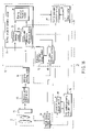
- FIG. 7 is a block diagram of a focus detection apparatus according to a second embodiment of the present invention.
- FIG. 8 is a flowchart for explaining processing of the focus detection apparatus according to the second embodiment.
- FIG. 9 is a diagram illustrating an example of a distance image
- FIG. 10 is a diagram illustrating an example of a mask used for mask processing in a DFF region extraction section
- FIG. 11 is a diagram illustrating another example of the mask used for mask processing in the DFF region extraction section
- FIG. 12 is a block diagram of a focus detection apparatus according to a second modification of the second embodiment.
- FIG. 13 is a diagram illustrating an example of an operation result of a second-order differential operation section
- FIG. 14 is a flowchart for explaining processing of the focus detection apparatus according to the second modification of the second embodiment
- FIG. 15 is a block diagram of a focus detection apparatus according to a third modification of the second embodiment.
- FIG. 16 is a block diagram of a focus detection apparatus according to a third embodiment of the present invention.
- FIG. 17 is a diagram illustrating a structure of a compact camera to which a focus detection apparatus according to a fourth embodiment of the present invention is applied.
- a focus detection apparatus is applied to a compact camera 10 as illustrated in FIG. 1 .
- the focus detection apparatus comprises an optical system 12 , an image acquisition device 14 and a luminance signal control section 16 which function as a luminance information acquiring section, a DFF/DFD switching section 18 , a distance estimating section 20 , a hill climbing operation section 22 , and an optical system control section 24 .
- the optical system 12 is formed of a plurality of lenses (taking lenses) aimed at acquiring images, and some of the lenses are configured to be driven in the optical axis direction to adjust the focus.
- the group of the lenses is called a focus lens.
- An image of a subject formed by the optical system 12 is converted into an electric signal by an optoelectronic transducer of the image acquisition device 14 .
- the converted electric signal is converted into a digital signal by the luminance signal control section 16 .
- the converted digital signal is called “luminance information”.
- the luminance information is input to the distance estimating section 20 and the hill climbing operation section 22 .
- the hill climbing operation section 22 which functions as a focus detection section performs processing to obtain a focusing result with higher accuracy.
- the hill climbing operation section 22 and the distance estimating section 20 are switched by the DFF/DFD switching section 18 .
- the optical system control section 24 functions as an arrangement control section for controlling the optical system 12 to a desired position, and is formed of an actuator and a drive circuit to drive the actuator, although not shown.
- the drive circuit when the focus lens position obtained by the hill climbing operation section 22 is input to the optical system control section 24 , the drive circuit generates a signal to be provided to the actuator to dispose the focus lens of the optical system 12 to the lens position, inputs the signal to the actuator, and thereby disposes the focus lens to the desired position.
- Operation control of the above sections is performed by a controller (not shown) which controls the compact camera 10 .
- the distance estimating section 20 estimates the subject distance by DFD method.
- the distance estimating section 20 is formed of a blurring parameter operation section 26 , a control parameter calculation section 28 , and an LUT storage section 30 .
- the blurring parameter operation section 26 includes a difference operation section 32 , a second-order differential operation section 34 , a blurring parameter calculation section 36 , and a buffer 38 .
- the difference operation section 32 calculates an image difference necessary for calculating the blurring parameter.
- the second-order operation section 34 calculates second-order differentials of the image, and calculates a mean value of second-order differential results obtained from two luminance information items having different blurring degrees.
- the blurring parameter calculation section 36 calculates the blurring parameter by dividing the image difference calculated by the difference operation section 32 by the mean value of the second-order differentials calculated by the second-order differential operation section 34 .
- the buffer 38 stores luminance information of the first image and a result of second-order differential thereof, since a plurality of luminance information items are obtained at different times by arranging the focus lens in different positions.
- the LUT storage section 30 stores relationship between the blurring parameter and the in-focus lens position in the form of a lookup table (LUT), as the relationship between the blurring parameter and the in-focus lens position.
- LUT lookup table
- the control parameter calculation section 28 determines the in-focus lens position corresponding to the blurring parameter calculated by the blurring parameter calculation section 36 , with reference to the LUT of the LUT storage section 30 .
- the hill climbing operation section 22 includes a high-pass filter (HPF) 40 , a DFF control parameter calculation section 42 , and an evaluation value storage section 44 .
- HPF 40 extracts high-frequency components of luminance information.
- the DFF control parameter calculation section 42 adds results of the HPF 40 , and calculates an evaluation value h(t).
- the evaluation value storage section 44 stores the lens position when the luminance information is acquired and the evaluation value calculated by the DFF control parameter calculation section 42 .
- the focus lens of the optical system 12 is driven to a predetermined first lens position L 1 by the optical system control section 24 , and the image acquisition device 14 and the luminance signal control section 16 acquire luminance information of a first image of the subject (Step S 10 ).
- the acquired first luminance information is supplied by the DFF/DFD switching section 18 to the distance estimating section 20 in accordance with control of the controller, and stored in the buffer 38 in the blurring parameter operation section 26 .
- the focus lens of the optical system 12 is driven to a predetermined second lens position L 2 by the optical system control section 24 , and the image acquisition device 14 and the luminance signal control section 16 acquire luminance information of a second image of the subject (Step S 12 ).
- the acquired second luminance information is supplied by the DFF/DFD switching section 18 to the distance estimating section 20 , in accordance with control by the controller.
- the distance estimating section 20 calculates a blurring parameter (Step S 14 ). Specifically, in the blurring parameter operation section 26 , the difference operation section 32 reads the first luminance information from the buffer 38 , and calculates a difference between the first luminance information and the second luminance information supplied from the DFF/DFD switching section 18 . Further, the second-order differential operation section 34 calculates the second-order differential of the second luminance information supplied from the DFF/DFD switching section 18 , and then reads the first luminance information from the buffer 38 and calculates the second-order differential thereof. Then, the second-order differential operation section 34 calculates a mean value of the calculated first and second second-order differentials. When the difference and the mean value of the second-order differentials are obtained, the blurring parameter calculation section 36 obtains a blurring parameter by dividing the output of the difference operation section 32 with the output of the second-order differential operation section 34 .
- the blurring parameter has linear relation to the reciprocal of the subject distance, and the subject distance and the in-focus lens position has a relationship of one-to-one correspondence. Therefore, the relationship between the blurring parameter and the in-focus lens position also has a one-to-one correspondence as illustrated in FIG. 4 .
- the relationship is stored as a table (LUT) in the LUT storage section 30 .
- the control parameter calculation section 28 calculates a subject distance corresponding to the blurring parameter.
- the distance information corresponding to the value of the subject distance is indicated by the position of the focus lens.
- the in-focus lens position DFD_LF corresponding to the blurring parameter obtained by the blurring parameter operation section 26 can be determined by linear approximation with reference to the table stored in the LUT storage section 30 (Step S 16 ).
- An estimated error ⁇ of the in-focus lens position DFD_LF obtained in this step is larger than the tolerance, since the in-focus lens position for the subject minutely varies due to lens barrel mounting error of individual cameras. Therefore, the control parameter calculation section 28 sets a position DFD_LF+ ⁇ , as the target lens position L(t ⁇ 1), which is distant from the estimated in-focus lens position by the estimated error ⁇ beyond the lens barrel mounting error, and inputs it to the optical system control section 24 .
- the optical system control section 24 drives the focus lens of the optical system 12 to the target lens position L(t ⁇ 1) (Step S 18 ).
- L(t ⁇ 1) represents the position of the focus lens, which has been driven from the in-focus lens position “DFD_LF” by the estimated error ⁇ toward a far point.
- L(t) represents the position of the focus lens, which has been driven from L(t ⁇ 1) by a predetermined amount ⁇ toward a near point.
- the position DFD_LF+ ⁇ is located between the lens position (L 2 ), in which the luminance information of the second image acquired in the process of calculating the blurring parameter has been obtained, and the in-focus lens position DFD_LF, as illustrated in FIG. 5 .
- focus detection operation by the hill climbing operation section 22 using the hill climbing method is started by control by the controller.
- luminance information of the subject is acquired at the lens position L(t ⁇ 1) by the image acquisition device 14 and the luminance signal control section 16 (Step S 20 ).
- the acquired luminance information is supplied to the hill climbing operation section 22 by the DFF/DFD switching section 18 , in accordance with control by the controller.
- the hill climbing operation section 22 extracts high-frequency components of the supplied luminance information by the HPF 40 , adds a result obtained by the HPF 40 by the DFF control parameter calculation section 42 , and calculates the evaluation value h(t ⁇ 1) (Step S 22 ).
- the calculated evaluation value is stored in the evaluation value storage section 44 together with the lens position, in which the luminance information is acquired, provided from the optical system control section 24 .
- the DFF control parameter calculation section 42 drives the focus lens of the optical system 12 by the optical system control section 24 by a predetermined amount ⁇ in the direction of the estimated in-focus lens position DFD_LF, on the basis of the lens position stored in the evaluation value storage section 44 (Step S 24 ). Then, the image acquisition device 14 and the luminance signal control section 16 acquire luminance information of the subject at the driven lens position L(t) (Step S 26 ), and the evaluation value is calculated again by the hill climbing operation section 22 as described above (Step S 28 ). The calculated evaluation value is stored in the evaluation value storage section 44 together with the lens position provided from the optical system control section 24 .
- Step S 30 it is determined whether the value of “h(t) ⁇ h(t ⁇ 1)” is positive or not.
- the current lens position L(t) is changed to the previous lens position (t ⁇ 1) (Step S 32 ), and the above processing is repeated by returning to Step S 24 .
- Step S 34 the DFF control parameter calculation section 42 estimates the peak position DFF_LF (Step S 34 ).
- the evaluation values and the lens positions stored in the evaluation value storage section 44 are subjected to approximation to quadric, and the lens position DFF_LF which serves as the peak of the curve is calculated.
- the DFF control parameter calculation section 42 provides the calculated lens position DFF_LF to the optical system control section 24 , and drive the focus lens of the optical system 12 to the position (Step S 36 ).
- focus detection is finished (Step S 38 ).
- variance may be determined from distribution of luminance, and a value in which variance increases as the more proper focus is attained may be determined.
- control of the actuator of the optical system control section 24 is only performed by an open-loop method
- a feedback control may be performed by an encoder attached to the actuator.
- the focus-detection apparatus of the first embodiment is also applicable to a single-lens reflex camera 46 as illustrated in FIG. 6 in the same manner.
- the optical system 12 is formed of a taking lens 12 A, a reflex mirror 12 B, and AF optical systems 12 C and 12 D to guide light beams to AF image acquisition devices 14 A and 14 B for focus detection.
- the taking lens 12 A includes a focus lens to adjust the focus.
- the image acquisition device 14 includes an image acquisition device 14 C for acquiring an image and two AF image acquisition devices ( 14 A and 14 B), one of the AF image acquisition devices is disposed in an optically equal position as that of the image acquisition device 14 C. In this modification, the AF image acquisition device 14 A is disposed in the position.
- the optical system control section 24 is formed of an actuator and a drive circuit to drive the focus lens of the taking lens 12 A.
- the distance estimating section 20 can acquire two luminance information items by the AF image acquisition devices 14 A and 14 B at predetermined one lens position L.
- the two luminance information which is acquired at the lens position L corresponds to the two luminance information at the lens position L 1 and L 2 .
- the blurring parameter is calculated by using the two luminance information items simultaneously acquired (Step S 14 ).
- the control parameter calculation section 28 estimates the in-focus lens position DFD_LF corresponding to the blurring parameter, with reference to the LUT storage section 30 , in the same manner as the first embodiment (Step S 16 ).
- a position distant from the estimated in-focus lens position DFD_LF by the estimated error ⁇ beyond the lens barrel mounting error is set as the target lens position DFD_LF+ ⁇ , and inputs the position to the optical system control section 24 (Step S 18 ).
- the optical system control section 24 disposes the focus lens in the target lens position.
- the hill climbing method is started thereafter.
- the hill climbing method is performed by using the luminance information acquired from the AF image acquisition device 14 A located in the position equal to the image acquisition device 14 C, among the two AF image acquisition devices ( 14 A, 14 B).
- the evaluation value h(t) is calculated in the same manner as the first embodiment (Step S 22 ), and the focus lens position DFF_LF which serves as the peak of the evaluation value is determined (Step S 24 to S 34 ).
- the focus lens is controlled to be located in the lens position (Step S 36 ), and focus detection is finished (Step S 38 ).
- a focus detection apparatus is applied to a compact camera 10 as illustrated in FIG. 1 .
- the focus detection apparatus comprises an optical system 12 , an image acquisition device 14 and a luminance signal control section 16 which function as a luminance information acquiring section, a DFF/DFD switching section 18 , a distance estimating section 20 , a hill climbing operation section 22 , and an optical system control section 24 , in the same manner as the first embodiment.
- the focus detection apparatus has a structure also including a DFF region extraction section 48 and an extraction information storage section 50 , which are used in both the distance estimating section 20 and the hill climbing operation section 22 .
- the DFF region extraction section 48 determines the in-focus lens position of the subject which has the nearest distance.
- the extraction information storage section 50 selects a block in which the subject having the shortest distance exists, and stores the address of the selected block.
- the focus lens of the optical system 12 is driven to a predetermined first lens position L 1 , and luminance information of a first image of the subject is acquired and supplied to the blurring parameter operation section 26 of the distance estimating section 20 (Step S 10 ). Thereafter, the focus lens of the optical system 12 is driven to a predetermined second lens position L 2 , luminance information of a second image of the subject is acquired and supplied to the blurring parameter operation section 26 of the distance estimating section 20 (Step S 12 ).
- the blurring parameter operation section 26 calculates a blurring parameter by division of a difference between two images acquired at different focus lens positions by the mean value of the second-order differentials of the two images (Step S 14 ).
- the blurring parameter has linear relation to the reciprocal of the subject distance, and the subject distance and the in-focus lens position has a relationship of one-to-one correspondence. Therefore, the relationship between the blurring parameter and the in-focus lens position also has a one-to-one correspondence.
- the relationship is stored as a table (LUT) in the LUT storage section 30 .
- the control parameter calculation section 28 determines the in-focus lens position for the subject by linear interpolation, by using the calculated blurring parameter and the information of the LUT.
- the in-focus lens position is calculated pixel by pixel for an edge portion of the image of the subject formed on the image plane.
- the control parameter calculation section 28 further converts the value of the in-focus lens position into a value of the subject distance, and thereby obtains an image as illustrated in FIG. 9 , which is called “distance image”.
- the distance image is supplied to the DFF region extraction section 48 , and the in-focus lens position DFD_LF of the subject having the shortest distance (Step S 16 ). Further, the DFF region extraction section 48 selects a block in which the subject exists, and causes the extraction information storage section 50 to store the address of the selected block(s) (A 11 and A 15 in the example of FIG. 9 ) (Step S 40 ).
- An estimated error ⁇ obtained in this step is larger than the tolerance, since the in-focus lens position for the subject minutely varies due to lens barrel mounting error of individual cameras. Therefore, the DFF region extraction section 48 sets a position which is distant from the estimated in-focus lens position by the estimated error ⁇ beyond the lens barrel mounting error as the target lens position DFD_LF+ ⁇ , and inputs it to the optical system control section 24 (Step S 18 ).
- the hill climbing method is started. Specifically, luminance information which has passed through the image acquisition device 14 and the luminance signal control section 16 is supplied to the DFF region extraction section 48 by the DFF/DFD switching section 18 , which has been switched to the hill climbing operation section 22 by the controller (not shown) (Step S 20 ). Since the extraction information storage section 50 stores in advance the address of the block in which the noted subject exists based on the result of DFD, the DFF region extraction section 48 extracts the luminance information in the block by mask processing (Step S 42 ). Generally, masks as illustrated in FIGS. 10 and 11 are used as the mask used for the mask processing.
- the HPF 40 extracts high-frequency components of the luminance information extracted by the DFF region extraction section 48 .
- the DFF control parameter calculation section 42 adds results of the HPF 40 and calculates the evaluation value (Step S 22 ).
- the calculated evaluation value is stored in the evaluation value storage section 44 together with the lens position, in which the luminance information is acquired, provided from the optical system control section 24 .
- Step S 24 the focus lens of the optical system 12 is driven by a predetermined amount ⁇ in the direction of the estimated in-focus lens position, on the basis of the current lens position stored in the evaluation value storage section 44 (Step S 24 ).
- luminance information is acquired (Step S 26 ), and the evaluation value is calculated again (Step S 28 ).
- the calculated evaluation value is stored in the evaluation value storage section 44 together with the lens position provided from the optical system control section 24 . This processing is repeated when the value of “h(t) ⁇ h(t ⁇ 1)” is positive (Step S 30 ).
- the DFF control parameter calculation section 42 estimates the peak (Step S 34 ). Specifically, the evaluation value and the lens position stored in the evaluation value storage section 44 are subjected to approximation to quadric, and the lens position DFF_LF which serves as the peak of the curve is calculated. Then, the DFF control parameter calculation section 42 provides the calculated lens position DFF_LF to the optical system control section 24 , and drives the focus lens of the optical system 12 to the position (Step S 36 ). Thereby, focus detection is finished (Step S 38 ).
- the noted subject is extracted by DFD, and the hill climbing method is performed only for a block corresponding to the result of DFD.
- the peak of the evaluation value can be calculated without being influenced by the evaluation value calculated from luminance information of the region other than the noted subject. Consequently, the in-focus accuracy can be improved.
- the hill climbing method is performed for part of blocks, not for the whole luminance information, the effect of reducing the operation cost is obtained.
- the second embodiment shows the case where the focus detection apparatus is applied to the compact camera 10 , it goes without saying that the focus detection apparatus is also applicable to single-lens reflex cameras as in the modification of the first embodiment, and an equivalent effect is obtained.
- extraction of the region may be performed by using a result of second-order differential determined in the process of calculating the blurring parameter as illustrated in FIG. 13 , by providing the operation result of the second-order differential operation section 34 to the DFF region extraction section 48 as illustrated in FIG. 12 .
- luminance information of the first image of the subject is acquired at the first lens position L 1 (Step S 10 ), and luminance information of the second image of the subject is acquired at the second lens position L 2 (Step S 12 ).
- the second-order differential operation section 34 determines second-order differentials of the two images acquired at the different focus-lens positions, and calculates the mean value of the second-order differentials.
- the mean value of the second-order differentials is supplied to the DFF region extraction section 48 as differential information.
- the DFF region extraction section 48 extracts a block in which the mean value of the second-order differentials of the two images exceeds a threshold value, as a region for which the blurring parameter is calculated, and stores the position information of the block (A 11 and A 15 in the example of FIG. 13 ) in the extraction information storage section 50 (Step S 44 ).
- the blurring parameter operation section 26 calculates the blurring parameter by division of the difference between the two images acquired at the different focus lens positions by the mean value of the second-order differentials of the two images (Step S 14 ). Then, the control parameter calculation section 28 determines the in-focus lens position for the subject by linear interpolation, by using the calculated blurring parameter and the information of the LUT stored in the LUT storage section 30 . The in-focus lens position is calculated pixel by pixel for the edge portion of the image of the subject formed on the image plane, and the position which has the shortest distance as the in-focus lens position DFD_LF of the subject (Step S 16 ).
- An estimated error ⁇ of the in-focus lens position DFD_LF obtained in this step is larger than the tolerance, since the in-focus lens position for the subject minutely varies due to lens barrel mounting error of individual cameras. Therefore, a position which is distant from the estimated in-focus lens position by the estimated error ⁇ beyond the lens barrel mounting error is set as the target lens position DFD_LF+ ⁇ , and inputs it to the optical system control section 24 . Then, the focus lens is driven (Step S 18 ).
- the hill climbing method is performed for the extracted block.
- the following processing is the same as that described in the second embodiment, and explanation thereof is omitted.
- the edge portion of the subject is extracted by the second-order differential, it is possible to extract the subject region existing on the image plane.
- the block having the highest edge intensity is extracted by the DFF region extraction section 48 , and the hill climbing method is performed by using only the luminance information of the extracted block. Thereby, the effect equal to the effect obtained by the second embodiment can be obtained.
- a main subject may be extracted on the basis of the structure of the edge.
- calculation of the blurring parameter by the parameter calculation section 36 in Step S 14 may be performed only for the block extracted by the DFF region extraction section 48 .
- the second modification can also be applied to single-lens reflex cameras as a matter of course.
- the equivalent effect can be obtained by performing extraction of the region by providing the operation result ( FIG. 13 ) of the second-order differential operation section 34 and the distance information ( FIG. 9 ) from the control parameter calculation section 28 to the DFF region extraction section 48 .
- the subject region can be extracted based on a result of the second-order differentials, as explained in the second modification. Further, erroneous extraction of the subject can be further prevented by using the distance information obtained from DFD, in comparison with the case of using only the result of second-order differentials.
- the third modification is also applicable to single-lens reflex cameras as a matter of course.
- a focus detection apparatus has a structure as illustrated in FIG. 16 .
- arrows of solid lines indicate flows of signals and information to perform the DFD method
- arrows of broken lines indicate flows of signals and information to perform the hill climbing method.
- arrows of alternate long and short dashed lines indicate flows of signals and information common to the DFD method and the hill climbing method.
- the output of the second-order differential operation section 34 is used first for distance estimation in the distance estimating section 20 , and for region extraction in the DFF region extraction section 48 as in the third modification of the second embodiment. Then, after the distance estimation, as indicated by the broken lines, the second-order differential operation section 34 subjects a luminance signal of a block extracted by the DFF region extraction section 48 to second-order differential, and supplies the result to the DFF control parameter calculation section 42 of the hill climbing method operation section 22 .
- the third embodiment has a structure in which the second-order differential operation section 34 of the blurring parameter operation section 26 is shared with and also used in the hill climbing operation section 22 .
- the second-order differential operation section 34 of the blurring parameter operation section 26 has an HPF characteristic which lets high-frequency components pass. Therefore, when the hill climbing method is performed, it is unnecessary for the hill climbing operation section 22 as described in the first or second embodiment to have an HPF, by using the second-order differential operation section 34 of the blurring parameter operation section 26 .
- the third embodiment having the above structure, it is unnecessary to provide an HPF to the hill climbing operation section 22 , and thus the size of the circuit can be reduced.
- the third embodiment shows the case where the focus detection apparatus is applied to the compact camera 10 , it goes without saying that the focus detection apparatus is also applicable to single-lens reflex cameras as in the modification of the first embodiment, and an equivalent effect is obtained.
- the first to third embodiments are explained with the structure in which the position of the optical system 12 is changed by driving the position of the focus lens and the aperture, two luminance information items having different blurring degrees are obtained, and an in-focus image is obtained by adjusting the position of the focus lens.
- an image acquisition device control section 52 which functions as a position control section for changing the position of the luminance information acquiring section by driving the image acquisition device 14 in the optical axis direction. Further, luminance information items having different blurring degrees are obtained by driving the image acquisition device 14 in the optical axis direction, instead of adjusting the position of the focus lens.
- the LUT storage section 30 should store relationship between the blurring parameter and the position of the image acquisition device 14 , as relationship between the blurring parameter and the in-focus position of light from the subject.
- This structure can also obtain the same effect as those of the first to third embodiments.
- the above operation sections and the calculation sections may be formed of one hardware such as DSP and CPU.
Landscapes
- Physics & Mathematics (AREA)
- General Physics & Mathematics (AREA)
- Engineering & Computer Science (AREA)
- Multimedia (AREA)
- Signal Processing (AREA)
- Computer Vision & Pattern Recognition (AREA)
- Optics & Photonics (AREA)
- Studio Devices (AREA)
- Automatic Focus Adjustment (AREA)
- Focusing (AREA)
Applications Claiming Priority (3)
| Application Number | Priority Date | Filing Date | Title |
|---|---|---|---|
| JP2005-330460 | 2005-11-15 | ||
| JP2005330460A JP2007139893A (ja) | 2005-11-15 | 2005-11-15 | 合焦検出装置 |
| PCT/JP2006/322265 WO2007058100A1 (ja) | 2005-11-15 | 2006-11-08 | 合焦検出装置 |
Related Parent Applications (1)
| Application Number | Title | Priority Date | Filing Date |
|---|---|---|---|
| PCT/JP2006/322265 Continuation WO2007058100A1 (ja) | 2005-11-15 | 2006-11-08 | 合焦検出装置 |
Publications (1)
| Publication Number | Publication Date |
|---|---|
| US20080297648A1 true US20080297648A1 (en) | 2008-12-04 |
Family
ID=38048487
Family Applications (1)
| Application Number | Title | Priority Date | Filing Date |
|---|---|---|---|
| US12/120,513 Abandoned US20080297648A1 (en) | 2005-11-15 | 2008-05-14 | Focus detection apparatus |
Country Status (3)
| Country | Link |
|---|---|
| US (1) | US20080297648A1 (enExample) |
| JP (1) | JP2007139893A (enExample) |
| WO (1) | WO2007058100A1 (enExample) |
Cited By (31)
| Publication number | Priority date | Publication date | Assignee | Title |
|---|---|---|---|---|
| US20090268985A1 (en) * | 2008-04-29 | 2009-10-29 | Earl Quong Wong | Reduced Hardware Implementation For A Two-Picture Depth Map Algorithm |
| US20100053417A1 (en) * | 2008-09-04 | 2010-03-04 | Zoran Corporation | Apparatus, method, and manufacture for iterative auto-focus using depth-from-defocus |
| US20100080482A1 (en) * | 2008-09-30 | 2010-04-01 | Earl Quong Wong | Fast Camera Auto-Focus |
| US20100321524A1 (en) * | 2009-06-17 | 2010-12-23 | Altek Corporation | Sharpness processing method and system for digital image |
| CN102103248A (zh) * | 2009-12-21 | 2011-06-22 | 索尼公司 | 具有置信度量的自动聚焦 |
| US20110181770A1 (en) * | 2010-01-27 | 2011-07-28 | Zoran Corporation | Depth from defocus calibration |
| US20110279699A1 (en) * | 2010-05-17 | 2011-11-17 | Sony Corporation | Image processing apparatus, image processing method, and program |
| US20120182448A1 (en) * | 2011-01-18 | 2012-07-19 | Tessera Technologies Ireland Limited | Distance estimation systems and method based on a two-state auto-focus lens |
| US20130033579A1 (en) * | 2010-02-19 | 2013-02-07 | Dual Aperture Inc. | Processing multi-aperture image data |
| US20130063566A1 (en) * | 2011-09-14 | 2013-03-14 | Canon Kabushiki Kaisha | Determining a depth map from images of a scene |
| CN103116739A (zh) * | 2011-10-13 | 2013-05-22 | 通用电气公司 | 用于散焦测距成像的系统和方法 |
| US20130208166A1 (en) * | 2012-02-13 | 2013-08-15 | Htc Corporation | Focus Adjusting Method and Image Capture Device thereof |
| US8553093B2 (en) | 2008-09-30 | 2013-10-08 | Sony Corporation | Method and apparatus for super-resolution imaging using digital imaging devices |
| US8644697B1 (en) | 2010-08-13 | 2014-02-04 | Csr Technology Inc. | Method for progressively determining depth from defocused images |
| US20140320704A1 (en) * | 2011-12-22 | 2014-10-30 | Sony Corporation | Imaging apparatus, method of controlling the same, and program |
| US8896747B2 (en) | 2012-11-13 | 2014-11-25 | Qualcomm Technologies, Inc. | Depth estimation based on interpolation of inverse focus statistics |
| US20150042839A1 (en) * | 2013-08-12 | 2015-02-12 | Canon Kabushiki Kaisha | Distance measuring apparatus, imaging apparatus, and distance measuring method |
| US9479690B2 (en) * | 2013-08-01 | 2016-10-25 | Fujifilm Corporation | Photographic apparatus and method for focusing control using two high pass filters |
| US9495751B2 (en) | 2010-02-19 | 2016-11-15 | Dual Aperture International Co. Ltd. | Processing multi-aperture image data |
| US9501834B2 (en) | 2011-08-18 | 2016-11-22 | Qualcomm Technologies, Inc. | Image capture for later refocusing or focus-manipulation |
| US9531938B2 (en) | 2014-03-28 | 2016-12-27 | Panasonic Intellectual Property Management Co., Ltd. | Image-capturing apparatus |
| US9571719B2 (en) | 2013-11-19 | 2017-02-14 | Panasonic Intellectual Property Management Co., Ltd. | Image-capturing apparatus |
| US20170154454A1 (en) * | 2015-11-30 | 2017-06-01 | Canon Kabushiki Kaisha | Image processing apparatus and image processing method |
| US20170169559A1 (en) * | 2015-12-09 | 2017-06-15 | Utechzone Co., Ltd. | Dynamic automatic focus tracking system |
| US9721357B2 (en) | 2015-02-26 | 2017-08-01 | Dual Aperture International Co. Ltd. | Multi-aperture depth map using blur kernels and edges |
| EP3422699A1 (en) * | 2017-06-28 | 2019-01-02 | Samsung Electronics Co., Ltd. | Electronic device including camera module |
| WO2019017585A1 (en) | 2017-07-18 | 2019-01-24 | Samsung Electronics Co., Ltd. | ELECTRONIC DEVICE FOR CONTROLLING THE DEVELOPMENT OF A LENS AND METHOD OF CONTROLLING THE SAME |
| US10237528B2 (en) | 2013-03-14 | 2019-03-19 | Qualcomm Incorporated | System and method for real time 2D to 3D conversion of a video in a digital camera |
| US10250805B2 (en) | 2014-03-19 | 2019-04-02 | Panasonic Intellectual Property Management Co., Ltd. | Imaging device for performing DFD processing at appropriate timing |
| KR20190087215A (ko) * | 2018-01-16 | 2019-07-24 | 삼성전자주식회사 | 전자 장치 및 전자 장치의 카메라 자동 초점 제어 방법 |
| US11323610B2 (en) | 2018-09-28 | 2022-05-03 | Samsung Electronics Co., Ltd. | Autofocus method and electronic device performing same |
Families Citing this family (6)
| Publication number | Priority date | Publication date | Assignee | Title |
|---|---|---|---|---|
| JP4933961B2 (ja) * | 2007-06-21 | 2012-05-16 | シャープ株式会社 | カメラモジュールのフォーカス調整装置及びフォーカス調整方法 |
| JP2013130762A (ja) * | 2011-12-22 | 2013-07-04 | Sony Corp | 撮像装置、その制御方法およびプログラム |
| JP5866537B2 (ja) * | 2013-11-19 | 2016-02-17 | パナソニックIpマネジメント株式会社 | 撮像装置 |
| JP6300670B2 (ja) * | 2014-07-09 | 2018-03-28 | キヤノン株式会社 | 焦点調節装置、焦点調節方法およびプログラム、並びに撮像装置 |
| JP6429724B2 (ja) * | 2015-05-19 | 2018-11-28 | キヤノン株式会社 | 撮像装置およびその制御方法 |
| JP2021108431A (ja) * | 2019-12-27 | 2021-07-29 | エスゼット ディージェイアイ テクノロジー カンパニー リミテッドSz Dji Technology Co.,Ltd | 制御装置、撮像装置、制御方法、及びプログラム |
Citations (4)
| Publication number | Priority date | Publication date | Assignee | Title |
|---|---|---|---|---|
| US4965840A (en) * | 1987-11-27 | 1990-10-23 | State University Of New York | Method and apparatus for determining the distances between surface-patches of a three-dimensional spatial scene and a camera system |
| US5225940A (en) * | 1991-03-01 | 1993-07-06 | Minolta Camera Kabushiki Kaisha | In-focus detection apparatus using video signal |
| US5264890A (en) * | 1992-01-06 | 1993-11-23 | Olympus Optical Co., Ltd. | Automatic focusing apparatus |
| US20040233320A1 (en) * | 2003-02-13 | 2004-11-25 | Nikon Corporation | Camera |
Family Cites Families (5)
| Publication number | Priority date | Publication date | Assignee | Title |
|---|---|---|---|---|
| EP0408224B1 (en) * | 1989-06-29 | 1995-09-06 | The Research Foundation Of State University Of New York | Computational methods and electronic camera apparatus for determining distance of objects, rapid autofocusing and obtaining improved focus images |
| JP2919706B2 (ja) * | 1993-06-17 | 1999-07-19 | 三洋電機株式会社 | オートフォーカスカメラ |
| JP2000199845A (ja) * | 1999-01-05 | 2000-07-18 | Ricoh Co Ltd | 自動合焦装置及び自動合焦方法 |
| JP2005094432A (ja) * | 2003-09-18 | 2005-04-07 | Matsushita Electric Ind Co Ltd | 画像サーバ |
| JP2006003803A (ja) * | 2004-06-21 | 2006-01-05 | Olympus Corp | 合焦情報取得装置及び合焦情報取得方法 |
-
2005
- 2005-11-15 JP JP2005330460A patent/JP2007139893A/ja active Pending
-
2006
- 2006-11-08 WO PCT/JP2006/322265 patent/WO2007058100A1/ja not_active Ceased
-
2008
- 2008-05-14 US US12/120,513 patent/US20080297648A1/en not_active Abandoned
Patent Citations (4)
| Publication number | Priority date | Publication date | Assignee | Title |
|---|---|---|---|---|
| US4965840A (en) * | 1987-11-27 | 1990-10-23 | State University Of New York | Method and apparatus for determining the distances between surface-patches of a three-dimensional spatial scene and a camera system |
| US5225940A (en) * | 1991-03-01 | 1993-07-06 | Minolta Camera Kabushiki Kaisha | In-focus detection apparatus using video signal |
| US5264890A (en) * | 1992-01-06 | 1993-11-23 | Olympus Optical Co., Ltd. | Automatic focusing apparatus |
| US20040233320A1 (en) * | 2003-02-13 | 2004-11-25 | Nikon Corporation | Camera |
Cited By (55)
| Publication number | Priority date | Publication date | Assignee | Title |
|---|---|---|---|---|
| US8280194B2 (en) | 2008-04-29 | 2012-10-02 | Sony Corporation | Reduced hardware implementation for a two-picture depth map algorithm |
| US20090268985A1 (en) * | 2008-04-29 | 2009-10-29 | Earl Quong Wong | Reduced Hardware Implementation For A Two-Picture Depth Map Algorithm |
| US20100053417A1 (en) * | 2008-09-04 | 2010-03-04 | Zoran Corporation | Apparatus, method, and manufacture for iterative auto-focus using depth-from-defocus |
| US8218061B2 (en) * | 2008-09-04 | 2012-07-10 | Csr Technology Inc. | Apparatus, method, and manufacture for iterative auto-focus using depth-from-defocus |
| US8194995B2 (en) | 2008-09-30 | 2012-06-05 | Sony Corporation | Fast camera auto-focus |
| US20100080482A1 (en) * | 2008-09-30 | 2010-04-01 | Earl Quong Wong | Fast Camera Auto-Focus |
| US8553093B2 (en) | 2008-09-30 | 2013-10-08 | Sony Corporation | Method and apparatus for super-resolution imaging using digital imaging devices |
| US20100321524A1 (en) * | 2009-06-17 | 2010-12-23 | Altek Corporation | Sharpness processing method and system for digital image |
| US8279307B2 (en) * | 2009-06-17 | 2012-10-02 | Altek Corporation | Sharpness processing method and system for digital image |
| CN102103248A (zh) * | 2009-12-21 | 2011-06-22 | 索尼公司 | 具有置信度量的自动聚焦 |
| EP2357788A1 (en) * | 2009-12-21 | 2011-08-17 | Sony Corporation | Autofocus with confidence measure |
| US20110150447A1 (en) * | 2009-12-21 | 2011-06-23 | Sony Corporation | Autofocus with confidence measure |
| US20110181770A1 (en) * | 2010-01-27 | 2011-07-28 | Zoran Corporation | Depth from defocus calibration |
| US8542313B2 (en) | 2010-01-27 | 2013-09-24 | Csr Technology Inc. | Depth from defocus calibration |
| US9495751B2 (en) | 2010-02-19 | 2016-11-15 | Dual Aperture International Co. Ltd. | Processing multi-aperture image data |
| US20130033579A1 (en) * | 2010-02-19 | 2013-02-07 | Dual Aperture Inc. | Processing multi-aperture image data |
| US8947523B2 (en) * | 2010-05-17 | 2015-02-03 | Sony Corporation | Image processing apparatus and associated methodology for blurring digital images |
| US20110279699A1 (en) * | 2010-05-17 | 2011-11-17 | Sony Corporation | Image processing apparatus, image processing method, and program |
| US8644697B1 (en) | 2010-08-13 | 2014-02-04 | Csr Technology Inc. | Method for progressively determining depth from defocused images |
| US8433187B2 (en) * | 2011-01-18 | 2013-04-30 | DigitalOptics Corporation MEMS | Distance estimation systems and method based on a two-state auto-focus lens |
| US20120182448A1 (en) * | 2011-01-18 | 2012-07-19 | Tessera Technologies Ireland Limited | Distance estimation systems and method based on a two-state auto-focus lens |
| US9501834B2 (en) | 2011-08-18 | 2016-11-22 | Qualcomm Technologies, Inc. | Image capture for later refocusing or focus-manipulation |
| US20130063566A1 (en) * | 2011-09-14 | 2013-03-14 | Canon Kabushiki Kaisha | Determining a depth map from images of a scene |
| US9836855B2 (en) * | 2011-09-14 | 2017-12-05 | Canon Kabushiki Kaisha | Determining a depth map from images of a scene |
| CN103116739A (zh) * | 2011-10-13 | 2013-05-22 | 通用电气公司 | 用于散焦测距成像的系统和方法 |
| US20140320704A1 (en) * | 2011-12-22 | 2014-10-30 | Sony Corporation | Imaging apparatus, method of controlling the same, and program |
| US20130208166A1 (en) * | 2012-02-13 | 2013-08-15 | Htc Corporation | Focus Adjusting Method and Image Capture Device thereof |
| US9049364B2 (en) * | 2012-02-13 | 2015-06-02 | Htc Corporation | Focus adjusting method and image capture device thereof |
| US8896747B2 (en) | 2012-11-13 | 2014-11-25 | Qualcomm Technologies, Inc. | Depth estimation based on interpolation of inverse focus statistics |
| US9215357B2 (en) | 2012-11-13 | 2015-12-15 | Qualcomm Technologies, Inc. | Depth estimation based on interpolation of inverse focus statistics |
| US10237528B2 (en) | 2013-03-14 | 2019-03-19 | Qualcomm Incorporated | System and method for real time 2D to 3D conversion of a video in a digital camera |
| US9479690B2 (en) * | 2013-08-01 | 2016-10-25 | Fujifilm Corporation | Photographic apparatus and method for focusing control using two high pass filters |
| US20150042839A1 (en) * | 2013-08-12 | 2015-02-12 | Canon Kabushiki Kaisha | Distance measuring apparatus, imaging apparatus, and distance measuring method |
| JP2015036632A (ja) * | 2013-08-12 | 2015-02-23 | キヤノン株式会社 | 距離計測装置、撮像装置、距離計測方法 |
| US9571719B2 (en) | 2013-11-19 | 2017-02-14 | Panasonic Intellectual Property Management Co., Ltd. | Image-capturing apparatus |
| US9832362B2 (en) | 2013-11-19 | 2017-11-28 | Panasonic Intellectual Property Management Co., Ltd. | Image-capturing apparatus |
| US10250805B2 (en) | 2014-03-19 | 2019-04-02 | Panasonic Intellectual Property Management Co., Ltd. | Imaging device for performing DFD processing at appropriate timing |
| US9531938B2 (en) | 2014-03-28 | 2016-12-27 | Panasonic Intellectual Property Management Co., Ltd. | Image-capturing apparatus |
| US9721357B2 (en) | 2015-02-26 | 2017-08-01 | Dual Aperture International Co. Ltd. | Multi-aperture depth map using blur kernels and edges |
| US9721344B2 (en) | 2015-02-26 | 2017-08-01 | Dual Aperture International Co., Ltd. | Multi-aperture depth map using partial blurring |
| US20170154454A1 (en) * | 2015-11-30 | 2017-06-01 | Canon Kabushiki Kaisha | Image processing apparatus and image processing method |
| US10121271B2 (en) * | 2015-11-30 | 2018-11-06 | Canon Kabushiki Kaisha | Image processing apparatus and image processing method |
| US10521895B2 (en) * | 2015-12-09 | 2019-12-31 | Utechzone Co., Ltd. | Dynamic automatic focus tracking system |
| US20170169559A1 (en) * | 2015-12-09 | 2017-06-15 | Utechzone Co., Ltd. | Dynamic automatic focus tracking system |
| CN109151301A (zh) * | 2017-06-28 | 2019-01-04 | 三星电子株式会社 | 包括相机模块的电子装置 |
| EP3422699A1 (en) * | 2017-06-28 | 2019-01-02 | Samsung Electronics Co., Ltd. | Electronic device including camera module |
| US11048061B2 (en) | 2017-06-28 | 2021-06-29 | Samsung Electronics Co., Ltd | Electronic device including camera module |
| WO2019017585A1 (en) | 2017-07-18 | 2019-01-24 | Samsung Electronics Co., Ltd. | ELECTRONIC DEVICE FOR CONTROLLING THE DEVELOPMENT OF A LENS AND METHOD OF CONTROLLING THE SAME |
| KR20190009104A (ko) * | 2017-07-18 | 2019-01-28 | 삼성전자주식회사 | 렌즈의 포커스를 제어하기 위한 전자 장치 및 전자 장치 제어 방법 |
| EP3642673A4 (en) * | 2017-07-18 | 2020-07-08 | Samsung Electronics Co., Ltd. | ELECTRONIC DEVICE FOR CONTROLLING THE DEVELOPMENT OF A LENS AND ASSOCIATED CONTROL METHOD |
| KR102382871B1 (ko) | 2017-07-18 | 2022-04-05 | 삼성전자주식회사 | 렌즈의 포커스를 제어하기 위한 전자 장치 및 전자 장치 제어 방법 |
| KR20190087215A (ko) * | 2018-01-16 | 2019-07-24 | 삼성전자주식회사 | 전자 장치 및 전자 장치의 카메라 자동 초점 제어 방법 |
| EP3718296A4 (en) * | 2018-01-16 | 2020-11-25 | Samsung Electronics Co., Ltd. | ELECTRONIC DEVICE AND CONTROL PROCEDURE FOR AUTOMATIC CAMERA FOCUS |
| KR102593303B1 (ko) | 2018-01-16 | 2023-10-25 | 삼성전자 주식회사 | 전자 장치 및 전자 장치의 카메라 자동 초점 제어 방법 |
| US11323610B2 (en) | 2018-09-28 | 2022-05-03 | Samsung Electronics Co., Ltd. | Autofocus method and electronic device performing same |
Also Published As
| Publication number | Publication date |
|---|---|
| WO2007058100A1 (ja) | 2007-05-24 |
| JP2007139893A (ja) | 2007-06-07 |
Similar Documents
| Publication | Publication Date | Title |
|---|---|---|
| US20080297648A1 (en) | Focus detection apparatus | |
| JP7039254B2 (ja) | レンズ制御装置、該レンズ制御装置を備える撮像装置、及びレンズ制御方法 | |
| US9389392B2 (en) | Imaging apparatus, control method for the imaging apparatus, lens unit, and control method for the lens unit | |
| CN101950116B (zh) | 一种应用于多主体场景的视频自动聚焦方法 | |
| US8120697B2 (en) | Imaging device and focusing method | |
| JP6154081B2 (ja) | 撮影装置、撮影装置本体、及びレンズ鏡筒 | |
| JP2008203294A (ja) | 撮像装置 | |
| JP2009145645A (ja) | 光学機器 | |
| JP2010139666A (ja) | 撮像装置 | |
| US8547474B2 (en) | Image pickup apparatus and control method thereof | |
| WO2016039146A1 (ja) | 撮影装置、撮影装置本体、及びレンズ鏡筒 | |
| JP2007086596A (ja) | カメラ | |
| JP7271353B2 (ja) | 撮像装置および波長取得方法 | |
| JP6808340B2 (ja) | レンズ制御装置、制御方法 | |
| JP2007199633A (ja) | 合焦検出装置 | |
| JP6432038B2 (ja) | 撮像装置 | |
| US6833538B2 (en) | Device for determining focused state of taking lens | |
| JP6154080B2 (ja) | 撮影装置、撮影装置本体、及びレンズ鏡筒 | |
| JP2003337277A (ja) | 光学機器 | |
| US7633545B2 (en) | Focus detecting system | |
| JP7087052B2 (ja) | レンズ制御装置、制御方法 | |
| US10536642B2 (en) | Image stabilization apparatus that corrects for image blurring, control method therefor, image pickup apparatus, and storage medium | |
| JP4573032B2 (ja) | オートフォーカスシステム | |
| JP2004258085A (ja) | オートフォーカスシステム | |
| JP6486086B2 (ja) | 撮像装置および撮像装置の制御方法 |
Legal Events
| Date | Code | Title | Description |
|---|---|---|---|
| AS | Assignment |
Owner name: OLYMPUS CORPORATION, JAPAN Free format text: ASSIGNMENT OF ASSIGNORS INTEREST;ASSIGNORS:FURUKI, SATOKO;YACHI, AKIKAZU;MATSUZAWA, TORU;AND OTHERS;REEL/FRAME:021346/0233;SIGNING DATES FROM 20080502 TO 20080526 |
|
| STCB | Information on status: application discontinuation |
Free format text: ABANDONED -- FAILURE TO RESPOND TO AN OFFICE ACTION |