US12188564B2 - Piston ring, and method for manufacturing same - Google Patents
Piston ring, and method for manufacturing same Download PDFInfo
- Publication number
- US12188564B2 US12188564B2 US17/793,654 US202117793654A US12188564B2 US 12188564 B2 US12188564 B2 US 12188564B2 US 202117793654 A US202117793654 A US 202117793654A US 12188564 B2 US12188564 B2 US 12188564B2
- Authority
- US
- United States
- Prior art keywords
- film
- piston ring
- range
- content
- hardness
- Prior art date
- Legal status (The legal status is an assumption and is not a legal conclusion. Google has not performed a legal analysis and makes no representation as to the accuracy of the status listed.)
- Active, expires
Links
- 238000000034 method Methods 0.000 title claims description 26
- 238000004519 manufacturing process Methods 0.000 title claims description 12
- 239000000758 substrate Substances 0.000 claims abstract description 25
- 229910052757 nitrogen Inorganic materials 0.000 claims description 14
- 238000005240 physical vapour deposition Methods 0.000 claims description 9
- IJGRMHOSHXDMSA-UHFFFAOYSA-N Atomic nitrogen Chemical compound N#N IJGRMHOSHXDMSA-UHFFFAOYSA-N 0.000 claims description 8
- 238000004140 cleaning Methods 0.000 claims description 7
- 239000013078 crystal Substances 0.000 description 16
- 230000000052 comparative effect Effects 0.000 description 14
- 238000012360 testing method Methods 0.000 description 12
- 229910007991 Si-N Inorganic materials 0.000 description 11
- 229910006294 Si—N Inorganic materials 0.000 description 11
- 229910052751 metal Inorganic materials 0.000 description 10
- 239000002184 metal Substances 0.000 description 8
- 230000015572 biosynthetic process Effects 0.000 description 6
- 238000011156 evaluation Methods 0.000 description 6
- 239000000463 material Substances 0.000 description 6
- 238000005259 measurement Methods 0.000 description 5
- 238000002441 X-ray diffraction Methods 0.000 description 4
- 230000006835 compression Effects 0.000 description 4
- 238000007906 compression Methods 0.000 description 4
- 238000009661 fatigue test Methods 0.000 description 4
- 238000007733 ion plating Methods 0.000 description 4
- 239000000203 mixture Substances 0.000 description 4
- 229910045601 alloy Inorganic materials 0.000 description 3
- 239000000956 alloy Substances 0.000 description 3
- 238000002485 combustion reaction Methods 0.000 description 3
- 239000000470 constituent Substances 0.000 description 3
- 239000007789 gas Substances 0.000 description 3
- 239000000314 lubricant Substances 0.000 description 3
- 150000004767 nitrides Chemical class 0.000 description 3
- 230000002093 peripheral effect Effects 0.000 description 3
- 239000012298 atmosphere Substances 0.000 description 2
- 230000008878 coupling Effects 0.000 description 2
- 238000010168 coupling process Methods 0.000 description 2
- 238000005859 coupling reaction Methods 0.000 description 2
- 238000006073 displacement reaction Methods 0.000 description 2
- 230000000694 effects Effects 0.000 description 2
- 239000000446 fuel Substances 0.000 description 2
- 239000003921 oil Substances 0.000 description 2
- PZNPLUBHRSSFHT-RRHRGVEJSA-N 1-hexadecanoyl-2-octadecanoyl-sn-glycero-3-phosphocholine Chemical compound CCCCCCCCCCCCCCCCCC(=O)O[C@@H](COP([O-])(=O)OCC[N+](C)(C)C)COC(=O)CCCCCCCCCCCCCCC PZNPLUBHRSSFHT-RRHRGVEJSA-N 0.000 description 1
- AFCARXCZXQIEQB-UHFFFAOYSA-N N-[3-oxo-3-(2,4,6,7-tetrahydrotriazolo[4,5-c]pyridin-5-yl)propyl]-2-[[3-(trifluoromethoxy)phenyl]methylamino]pyrimidine-5-carboxamide Chemical compound O=C(CCNC(=O)C=1C=NC(=NC=1)NCC1=CC(=CC=C1)OC(F)(F)F)N1CC2=C(CC1)NN=N2 AFCARXCZXQIEQB-UHFFFAOYSA-N 0.000 description 1
- 229910000639 Spring steel Inorganic materials 0.000 description 1
- ATJFFYVFTNAWJD-UHFFFAOYSA-N Tin Chemical compound [Sn] ATJFFYVFTNAWJD-UHFFFAOYSA-N 0.000 description 1
- 230000001133 acceleration Effects 0.000 description 1
- 239000002199 base oil Substances 0.000 description 1
- 238000005422 blasting Methods 0.000 description 1
- 238000005238 degreasing Methods 0.000 description 1
- 238000011161 development Methods 0.000 description 1
- 229910003460 diamond Inorganic materials 0.000 description 1
- 239000010432 diamond Substances 0.000 description 1
- 238000004453 electron probe microanalysis Methods 0.000 description 1
- 238000002347 injection Methods 0.000 description 1
- 239000007924 injection Substances 0.000 description 1
- 238000005461 lubrication Methods 0.000 description 1
- 229910001105 martensitic stainless steel Inorganic materials 0.000 description 1
- 230000013011 mating Effects 0.000 description 1
- 239000012299 nitrogen atmosphere Substances 0.000 description 1
- 230000000704 physical effect Effects 0.000 description 1
- 230000002250 progressing effect Effects 0.000 description 1
- 239000000243 solution Substances 0.000 description 1
- 238000004544 sputter deposition Methods 0.000 description 1
- 238000010998 test method Methods 0.000 description 1
- 229910052726 zirconium Inorganic materials 0.000 description 1
Images

Classifications
-
- F—MECHANICAL ENGINEERING; LIGHTING; HEATING; WEAPONS; BLASTING
- F16—ENGINEERING ELEMENTS AND UNITS; GENERAL MEASURES FOR PRODUCING AND MAINTAINING EFFECTIVE FUNCTIONING OF MACHINES OR INSTALLATIONS; THERMAL INSULATION IN GENERAL
- F16J—PISTONS; CYLINDERS; SEALINGS
- F16J9/00—Piston-rings, e.g. non-metallic piston-rings, seats therefor; Ring sealings of similar construction
- F16J9/26—Piston-rings, e.g. non-metallic piston-rings, seats therefor; Ring sealings of similar construction characterised by the use of particular materials
-
- C—CHEMISTRY; METALLURGY
- C23—COATING METALLIC MATERIAL; COATING MATERIAL WITH METALLIC MATERIAL; CHEMICAL SURFACE TREATMENT; DIFFUSION TREATMENT OF METALLIC MATERIAL; COATING BY VACUUM EVAPORATION, BY SPUTTERING, BY ION IMPLANTATION OR BY CHEMICAL VAPOUR DEPOSITION, IN GENERAL; INHIBITING CORROSION OF METALLIC MATERIAL OR INCRUSTATION IN GENERAL
- C23C—COATING METALLIC MATERIAL; COATING MATERIAL WITH METALLIC MATERIAL; SURFACE TREATMENT OF METALLIC MATERIAL BY DIFFUSION INTO THE SURFACE, BY CHEMICAL CONVERSION OR SUBSTITUTION; COATING BY VACUUM EVAPORATION, BY SPUTTERING, BY ION IMPLANTATION OR BY CHEMICAL VAPOUR DEPOSITION, IN GENERAL
- C23C14/00—Coating by vacuum evaporation, by sputtering or by ion implantation of the coating forming material
- C23C14/0021—Reactive sputtering or evaporation
-
- C—CHEMISTRY; METALLURGY
- C23—COATING METALLIC MATERIAL; COATING MATERIAL WITH METALLIC MATERIAL; CHEMICAL SURFACE TREATMENT; DIFFUSION TREATMENT OF METALLIC MATERIAL; COATING BY VACUUM EVAPORATION, BY SPUTTERING, BY ION IMPLANTATION OR BY CHEMICAL VAPOUR DEPOSITION, IN GENERAL; INHIBITING CORROSION OF METALLIC MATERIAL OR INCRUSTATION IN GENERAL
- C23C—COATING METALLIC MATERIAL; COATING MATERIAL WITH METALLIC MATERIAL; SURFACE TREATMENT OF METALLIC MATERIAL BY DIFFUSION INTO THE SURFACE, BY CHEMICAL CONVERSION OR SUBSTITUTION; COATING BY VACUUM EVAPORATION, BY SPUTTERING, BY ION IMPLANTATION OR BY CHEMICAL VAPOUR DEPOSITION, IN GENERAL
- C23C14/00—Coating by vacuum evaporation, by sputtering or by ion implantation of the coating forming material
- C23C14/02—Pretreatment of the material to be coated
- C23C14/021—Cleaning or etching treatments
- C23C14/022—Cleaning or etching treatments by means of bombardment with energetic particles or radiation
-
- C—CHEMISTRY; METALLURGY
- C23—COATING METALLIC MATERIAL; COATING MATERIAL WITH METALLIC MATERIAL; CHEMICAL SURFACE TREATMENT; DIFFUSION TREATMENT OF METALLIC MATERIAL; COATING BY VACUUM EVAPORATION, BY SPUTTERING, BY ION IMPLANTATION OR BY CHEMICAL VAPOUR DEPOSITION, IN GENERAL; INHIBITING CORROSION OF METALLIC MATERIAL OR INCRUSTATION IN GENERAL
- C23C—COATING METALLIC MATERIAL; COATING MATERIAL WITH METALLIC MATERIAL; SURFACE TREATMENT OF METALLIC MATERIAL BY DIFFUSION INTO THE SURFACE, BY CHEMICAL CONVERSION OR SUBSTITUTION; COATING BY VACUUM EVAPORATION, BY SPUTTERING, BY ION IMPLANTATION OR BY CHEMICAL VAPOUR DEPOSITION, IN GENERAL
- C23C14/00—Coating by vacuum evaporation, by sputtering or by ion implantation of the coating forming material
- C23C14/06—Coating by vacuum evaporation, by sputtering or by ion implantation of the coating forming material characterised by the coating material
- C23C14/0641—Nitrides
-
- C—CHEMISTRY; METALLURGY
- C23—COATING METALLIC MATERIAL; COATING MATERIAL WITH METALLIC MATERIAL; CHEMICAL SURFACE TREATMENT; DIFFUSION TREATMENT OF METALLIC MATERIAL; COATING BY VACUUM EVAPORATION, BY SPUTTERING, BY ION IMPLANTATION OR BY CHEMICAL VAPOUR DEPOSITION, IN GENERAL; INHIBITING CORROSION OF METALLIC MATERIAL OR INCRUSTATION IN GENERAL
- C23C—COATING METALLIC MATERIAL; COATING MATERIAL WITH METALLIC MATERIAL; SURFACE TREATMENT OF METALLIC MATERIAL BY DIFFUSION INTO THE SURFACE, BY CHEMICAL CONVERSION OR SUBSTITUTION; COATING BY VACUUM EVAPORATION, BY SPUTTERING, BY ION IMPLANTATION OR BY CHEMICAL VAPOUR DEPOSITION, IN GENERAL
- C23C14/00—Coating by vacuum evaporation, by sputtering or by ion implantation of the coating forming material
- C23C14/22—Coating by vacuum evaporation, by sputtering or by ion implantation of the coating forming material characterised by the process of coating
- C23C14/24—Vacuum evaporation
- C23C14/32—Vacuum evaporation by explosion; by evaporation and subsequent ionisation of the vapours, e.g. ion-plating
-
- C—CHEMISTRY; METALLURGY
- C23—COATING METALLIC MATERIAL; COATING MATERIAL WITH METALLIC MATERIAL; CHEMICAL SURFACE TREATMENT; DIFFUSION TREATMENT OF METALLIC MATERIAL; COATING BY VACUUM EVAPORATION, BY SPUTTERING, BY ION IMPLANTATION OR BY CHEMICAL VAPOUR DEPOSITION, IN GENERAL; INHIBITING CORROSION OF METALLIC MATERIAL OR INCRUSTATION IN GENERAL
- C23C—COATING METALLIC MATERIAL; COATING MATERIAL WITH METALLIC MATERIAL; SURFACE TREATMENT OF METALLIC MATERIAL BY DIFFUSION INTO THE SURFACE, BY CHEMICAL CONVERSION OR SUBSTITUTION; COATING BY VACUUM EVAPORATION, BY SPUTTERING, BY ION IMPLANTATION OR BY CHEMICAL VAPOUR DEPOSITION, IN GENERAL
- C23C14/00—Coating by vacuum evaporation, by sputtering or by ion implantation of the coating forming material
- C23C14/22—Coating by vacuum evaporation, by sputtering or by ion implantation of the coating forming material characterised by the process of coating
- C23C14/24—Vacuum evaporation
- C23C14/32—Vacuum evaporation by explosion; by evaporation and subsequent ionisation of the vapours, e.g. ion-plating
- C23C14/325—Electric arc evaporation
-
- F—MECHANICAL ENGINEERING; LIGHTING; HEATING; WEAPONS; BLASTING
- F02—COMBUSTION ENGINES; HOT-GAS OR COMBUSTION-PRODUCT ENGINE PLANTS
- F02F—CYLINDERS, PISTONS OR CASINGS, FOR COMBUSTION ENGINES; ARRANGEMENTS OF SEALINGS IN COMBUSTION ENGINES
- F02F5/00—Piston rings, e.g. associated with piston crown
Definitions
- the present disclosure relates to a piston ring and a method for manufacturing the same.
- a piston ring is used in engines of automobiles or the like.
- the piston ring is mounted in a groove provided in an outer peripheral surface of a piston.
- the piston ring is required to contribute to high performance of an engine and to a reduction in fuel consumption through characteristics such as wear resistance and seizure resistance.
- various efforts have been made to improve the wear resistance of the piston ring.
- Patent Literature 1 is intended to provide a sliding member having excellent wear resistance even under severe conditions in an engine to which fuel direct injection or exhaust gas recirculation (EGR) is applied.
- a substrate is covered with a film made of a metal nitride, a metal carbide, or a metal carbonitride and having a mixed structure of a crystal phase and an amorphous phase.
- Patent Literature 2 The invention described in Patent Literature 2 is intended to provide a piston ring for an internal combustion engine having both wear resistance, crack resistance, and peeling resistance.
- a hard film containing Cr, N, and Si as constituent elements, having the same crystal structure as that of CrN, and being composed of a crystal phase in which Si is solid-solved in a crystal lattice of the crystal structure at an atomic ratio of 1% to 9.5% is formed on at least an outer peripheral sliding surface of the piston ring.
- Patent Literatures 1 and 2 disclose that films are formed by an ion plating method.
- a CrN-based film, a TiN-based film, and a laminated film thereof formed by the ion plating method improve the wear resistance and the peeling resistance of the piston ring.
- the usage environment of the piston ring is assumed to become more severe, there is still room for improving the wear resistance and the peeling resistance of these films.
- the inventors developed a film in which Si is added to CrN. It was known that the film in which Si is added to CrN (hereinafter, referred to as a “Cr—Si—N-based film” in some cases) has fine crystal grains because of the addition of Si, and as a result, is dense and has a large hardness.
- the development policy at that time placed emphasis on improving the wear resistance of the film by increasing the hardness.
- cracks occurring in the film could not be sufficiently suppressed and the film was not put into practical use.
- the present disclosure provides a piston ring on which a film containing Si and N is provided and in which all of peeling resistance, crack resistance, and wear resistance are at a sufficiently high level, and a method for manufacturing the same.
- the Cr—Si—N-based film of the related art has a large hardness whereas cracks are likely to be formed in the film, which is a problem.
- the cracks in the film are a cause of peeling. Since the piston ring is exposed to continuous sliding and to a repeated load, it has been considered that the application of the Cr—Si—N-based film of the related art to the piston ring is difficult.
- the inventors have specified conditions of a physical vapor deposition method in which a film capable of achieving all of peeling resistance, crack resistance, and wear resistance at a sufficiently high level is formed, and has completed the following inventions.
- a method for manufacturing a piston ring according to the present disclosure includes: (A) a step of cleaning a surface of a substrate of the piston ring; and (B) a step of forming a film containing Si and N in a chamber using a physical vapor deposition method so as to cover at least a part of the surface of the substrate.
- a pressure in the chamber is set in a range of 2 to 6 Pa and a bias voltage is set in a range of ⁇ 5 to ⁇ 18 V such that the film satisfying the following conditions is formed.
- the pressure condition (2 to 6 Pa) in the chamber allows a higher pressure than that of film formation conditions of the Cr—Si—N-based film of the related art, and an absolute value (5 to 18) of the bias voltage condition ( ⁇ 5 to ⁇ 18 V) is a smaller value than that of the film formation conditions of the Cr—Si—N-based film of the related art.
- the piston ring in which all of peeling resistance, crack resistance, and wear resistance are at a sufficiently high level can be manufactured by forming the film under conditions satisfying these values.
- a piston ring according to the present disclosure includes: a substrate; and a film containing Si and N, that is provided to cover at least a part of a surface of the substrate.
- the film satisfies the following conditions.
- a hardness of the film is 1000 HV0.1 to 1800 HV0.1. This hardness is softer than that of the Cr—Si—N-based film of the related art, but is a hardness that is sufficient as that of the film of the piston ring. It is preferable that a ratio H/E of a hardness H (GPa) of the film obtained by a nanoindenter and a Young's modulus E (GPa) of the film is 0.04 to 0.07. When the ratio H/E is within the above range, the film can be appropriately elastically deformed, and accordingly, a Hertz stress caused by sliding is reduced, and excellent peeling resistance is achieved.
- Me is, for example, Cr.
- a Cr content is 40 at % or more.
- a texture coefficient of CrN (111) is 0.4 or more.
- the present disclosure provides the piston ring on which the film containing Si and N is provided and in which all of peeling resistance, crack resistance, and wear resistance are at a sufficiently high level, and the method for manufacturing the same.
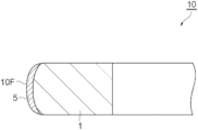
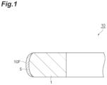
- FIG. 1 is a cross-sectional view schematically showing one embodiment of a piston ring of the present disclosure.
- FIG. 2 is a schematic view showing a configuration of a sliding fatigue tester.
- FIG. 1 is a cross-sectional view schematically showing a piston ring according to the present embodiment.
- a piston ring 10 shown in FIG. 1 is a compression ring for an internal combustion engine (for example, an automobile engine).
- the compression ring is mounted in a ring groove formed in a side surface of a piston.
- the compression ring is a ring exposed to particularly an environment where the thermal load of the engine is high.
- the piston ring 10 has an annular shape and has, for example, an outer diameter of 40 to 300 mm.
- the term “annular shape” referred to here does not necessarily mean a closed circle, and the piston ring 10 may include a joint portion.
- the piston ring 10 may have a perfect circular shape or an elliptical shape in a plan view.
- the piston ring 10 has a substantially rectangular shape in the cross section shown in FIG. 1 , and a sliding surface 10 F may be rounded to bulge outward.
- the piston ring 10 includes a substrate 1 and a film 5 provided on an outer peripheral surface (surface corresponding to the sliding surface 10 F) of the substrate 1 .
- the substrate 1 is made of an alloy having a heat resisting property. Specific examples of the alloy include spring steel, martensitic stainless steel, and the like.
- a nitride layer may be formed on a surface of the substrate 1 .
- the film 5 forms the sliding surface 10 F.
- the film 5 is made of a Me-Si—N-based material (Me indicates a metal element).
- a thickness of the film 5 is, for example, 5 to 70 ⁇ m, preferably 10 to 50 ⁇ m. When the thickness of the film 5 is 5 ⁇ m or more, there is a tendency that the durability of the piston ring 10 can be increased, and on the other hand, when the thickness is 70 ⁇ m or less, a high productivity of the film 5 can be secured.
- the metal element Me is, for example, Cr, Ti, Al, Zr, Nb, or the like.
- a Me content in the Me-Si—N-based material is preferably 40 at % or more, more preferably 40 to 55 at %, and further preferably 45 to 52 at %.
- the Me-Si—N-based material may contain one metal element or two or more metal elements. Among these metal elements, Cr is preferable in that an atomic radius of Cr is close to that of Si to be solid-solved.
- a Si content of the film 5 is 1.1 to 7.5 at %, preferably 1.5 to 7.0 at %, and more preferably 2.0 to 5.0 at %.
- the film 5 having a Si content of 1.1 at % or more is composed of fine crystal grains and has excellent hardness.
- an appropriate amount of amorphous phase is likely to be formed in the film 5 . It is inferred that the amorphous phase contributes to suppressing cracks.
- the Si content of the film 5 can be adjusted by a Si content of a target used when the film 5 is formed by a physical vapor deposition method (PVD method).
- a crystallite size of the film 5 is 10 to 30 nm, preferably 15 to 25 nm. In the case of a crystallite size of 30 nm or less, even when the film 5 is worn, a wear amount at a time is reduced, and the wear resistance is improved.
- a compressive residual stress of the film 5 is 400 to 800 MPa.
- the residual stress (compression) of the film 5 is within the above range, a stress difference between the film 5 and the substrate 1 (an alloy or a nitride layer) can be reduced, and accordingly, peeling at an interface between the substrate 1 and the film 5 can be suppressed.
- cracks in the film 5 that are likely to occur because of the addition of Si can be suppressed.
- a texture coefficient of each crystal plane satisfies the following conditions. Balancing the crystal orientations of the film 5 can interfere with the growth of cracks and can effectively prevent the peeling of the film 5 caused by the coupling of the cracks.
- a hardness of the film 5 is preferably 1000 HV0.1 to 1800 HV0.1, more preferably 1100 HV0.1 to 1500 HV0.1.
- a ratio H/E of a hardness H (GPa) of the film 5 obtained by a nanoindenter and a Young's modulus E (GPa) of the film 5 is preferably 0.04 to 0.07, more preferably 0.05 to 0.06. When the ratio H/E is within the above range, the film 5 can be appropriately elastically deformed, and accordingly, a Hertz stress caused by sliding is reduced, and excellent peeling resistance is achieved.
- the manufacturing method of the present embodiments includes the following steps.
- the step (a) is a step of cleaning the surface of the substrate 1 prior to the formation of the film 5 .
- a cleaning process by degreasing or shot blasting may be performed.
- bombardment cleaning may be performed in a chamber.
- the formation of the film 5 in the step (b) may be performed by the physical vapor deposition method.
- the formation of the film 5 is performed after the inside of the chamber is set to a nitrogen atmosphere.
- Examples of the physical vapor deposition method include an ion plating method, a sputtering method, and the like. All of these physical vapor deposition methods are performed in a vacuum chamber, and a nitrogen pressure of the vacuum chamber is set in a range of 2 to 6 Pa. In addition, a bias voltage is set in a range of ⁇ 5 to ⁇ 18 V.
- the Si content of the film 5 can be adjusted by changing a Si content of a target.
- the Si content of the film 5 may be adjusted by supplying a Si-containing gas into the chamber.
- the hardness of the film 5 can be adjusted, and the crystal orientations and the crystallite size can be adjusted by the Si content of the film 5 .
- the physical properties of the film 5 can be adjusted by a temperature when the film 5 is formed (film forming temperature).
- the film forming temperature may be, for example, 550° C. or less.
- the residual stress and the hardness of the film 5 may be adjusted by adjusting the nitrogen pressure in the chamber and the bias voltage.
- At least one of the following conditions may be adopted to form the film 5 that is relatively soft even though the film 5 contains Si.
- the nitrogen pressure in the chamber is set to be high.
- the pressure is, for example, 4.0 to 6.0 Pa.
- the bias voltage (absolute value) is set to a small value.
- the bias voltage is, for example, ⁇ 5 to ⁇ 10 V.
- the piston ring 10 in which all of peeling resistance, crack resistance, and wear resistance are at a sufficiently high level can be manufactured.
- rings having the following composition were prepared.
- the piston rings according to examples and comparative examples were produced as follows. Namely, first, the substrates were degreased and cleaned and then installed in a chamber. Next, the substrates in the chamber were subjected to bombardment cleaning. Thereafter, a film (thickness: approximately 20 ⁇ m) was formed on a surface of each of the substrates under the conditions shown in Tables 1 and 2 by the ion plating method. Note that the film formation temperature was set to 500° C. An arc current was set to 150 A.
- Tables 1 and 2 show characteristics of the films of the piston rings according to the examples and the comparative examples. Note that each characteristic was measured by the following methods.
- a Si content of the films was measured using EPMA (device name: JXA-8100 and manufactured by JEOL Ltd.) under measurement conditions where an acceleration voltage was set to 15 kV, an irradiation current was set to 5.0 ⁇ 10 ⁇ 8 A, and a beam diameter was set to 10 ⁇ m.
- EPMA device name: JXA-8100 and manufactured by JEOL Ltd.
- an acceleration voltage was set to 15 kV
- an irradiation current was set to 5.0 ⁇ 10 ⁇ 8 A
- a beam diameter was set to 10 ⁇ m.
- Crystal orientations of the films were evaluated by a texture coefficient of each crystal plane obtained from X-ray diffraction data obtained by an X-ray diffractometer (device name: SmartLab and manufactured by Rigaku Corporation).
- l (hkl) is an X-ray diffraction intensity of a measured plane (hkl)
- l 0 (hkl) is a standard X-ray diffraction intensity described in the JCPDS file.
- a residual stress of the films was measured using an X-ray stress measurement device (device name: PSPC micro-area X-ray residual stress measurement system and manufactured by Rigaku Corporation).
- K is a stress constant (obtained from a Young's modulus, a Poisson's ratio, and a reflection angle ⁇ in a non-distorted state), and ⁇ 762 MPa was used.
- the measurement was performed by an iso-inclination method under conditions where a Cr target X-ray tube was used, a voltage was set to 35 kV, a current was set to 40 mA, a collimator of 1 mm was used, six points (0, 18, 27, 33, 39, and 45 deg.) were set as ⁇ , a measurement time was set to 90 seconds, and a diffraction angle CrN (311), 2 ⁇ was set to 132.86°.
- the negative notation in Tables 1 and 2 means a compressive residual stress.
- a hardness of the films was obtained by performing a hardness test with a test load of 0.98 N using a Vickers hardness tester (device name: HM-220 and manufactured by Mitutoyo Corporation) based on the method specified in ISO6507.
- the hardness H of the films and the Young's modulus E of the films obtained by a nanoindenter were obtained using a nanoindentation hardness tester (device name: ENT-1100a and manufactured by ELIONIX INC.). Namely, a hardness test was performed with a test load of 0.4 N using a diamond indenter of which the tip shape is a regular triangular pyramid shape (Berkovich type), based on the test method specified in ISO14577, and the hardness H and the Young's modulus E of the films were obtained from a “load-displacement curve” obtained from the load applied to the indenter and a displacement of the indenter during the test.
- a nanoindentation hardness tester device name: ENT-1100a and manufactured by ELIONIX INC.
- K is a Scherrer constant and is 0.94
- ⁇ is a wavelength of X-rays (Cu: 1.5406 ⁇ )
- ⁇ is a half value width
- ⁇ is a Bragg angle.
- a tester 50 shown in FIG. 2 includes a drum 51 that is rotatable, a mechanism that brings a test piece S (piston ring cut piece) into contact with a surface of the drum 51 , a mechanism that repeatedly applies a load to the test piece S, and a mechanism that supplies a lubricant to a sliding portion. Accordingly, the test piece can be worn in a relatively short time. Test conditions are as follows.
- Example 2 Com- parative Com- parative Com- parative Com- parative Com- parative Com- parative Example 1
- Example 2 Example 3
- Example 4 Example 5
- Example 6 Composition of target Cr content (at %) 90 90 90 100 99 97 Si content (at %) 10 10 0 1 3 Chamber Pressure (Pa) 4.0 1.5 1.5 4.0 4.0 4.0 Atmosphere N 2 N 2 N 2 N 2 N 2 Bias voltage (V) -20 0 ⁇ 10 ⁇ 10 ⁇ 10 ⁇ 10 Film Constituent element CrSiN CrSiN CrSiN CrN CrSiN CrSiN CrSiN CrSiN characteristics Si content (at %) 3.4 3.2 3.3 ⁇ 0.2 0.4 Texture CrN (111) 0.6 1.0 1.1 0.4 0.7 0.7 coefficient CrN (200) 2.0 1.5 1.4 2.3 1.9 1.7 CrN (220) 0.4 0.5 0.6 0.3 0.4 0.6 Residual stress (MPa) ⁇ 914 ⁇ 834 ⁇ 1050 ⁇
- the present disclosure provides the piston ring on which the film containing Si and N is provided and in which all of peeling resistance, crack resistance, and wear resistance are at a sufficiently high level, and the method for manufacturing the same.
Landscapes
- Chemical & Material Sciences (AREA)
- Engineering & Computer Science (AREA)
- Mechanical Engineering (AREA)
- Chemical Kinetics & Catalysis (AREA)
- Materials Engineering (AREA)
- Metallurgy (AREA)
- Organic Chemistry (AREA)
- General Engineering & Computer Science (AREA)
- Pistons, Piston Rings, And Cylinders (AREA)
- Physical Vapour Deposition (AREA)
Applications Claiming Priority (3)
| Application Number | Priority Date | Filing Date | Title |
|---|---|---|---|
| JP2020-010754 | 2020-01-27 | ||
| JP2020010754 | 2020-01-27 | ||
| PCT/JP2021/002102 WO2021153425A1 (ja) | 2020-01-27 | 2021-01-21 | ピストンリング及びその製造方法 |
Publications (2)
| Publication Number | Publication Date |
|---|---|
| US20230083774A1 US20230083774A1 (en) | 2023-03-16 |
| US12188564B2 true US12188564B2 (en) | 2025-01-07 |
Family
ID=77079717
Family Applications (1)
| Application Number | Title | Priority Date | Filing Date |
|---|---|---|---|
| US17/793,654 Active 2041-05-03 US12188564B2 (en) | 2020-01-27 | 2021-01-21 | Piston ring, and method for manufacturing same |
Country Status (5)
| Country | Link |
|---|---|
| US (1) | US12188564B2 (https=) |
| EP (1) | EP4080033A4 (https=) |
| JP (2) | JP7085692B2 (https=) |
| CN (1) | CN115003936B (https=) |
| WO (1) | WO2021153425A1 (https=) |
Families Citing this family (2)
| Publication number | Priority date | Publication date | Assignee | Title |
|---|---|---|---|---|
| WO2025074480A1 (ja) * | 2023-10-02 | 2025-04-10 | 株式会社リケン | 摺動部材およびピストンリング |
| KR20260047558A (ko) * | 2024-09-30 | 2026-04-08 | 가부시끼가이샤 리켄 | 슬라이딩 부재의 제조 방법, 슬라이딩 부재 및 피스톤 링 |
Citations (15)
| Publication number | Priority date | Publication date | Assignee | Title |
|---|---|---|---|---|
| WO2002052179A1 (en) | 2000-12-26 | 2002-07-04 | Kabushiki Kaisha Riken | Piston ring and method of producing the same |
| JP2002266697A (ja) | 2001-03-08 | 2002-09-18 | Ion Engineering Research Institute Corp | 摺動部材およびその製造方法 |
| US20080007006A1 (en) | 2006-07-06 | 2008-01-10 | Teikoku Piston Ring Co., Ltd. | Piston ring for internal combustion engines |
| CN101210318A (zh) | 2007-12-25 | 2008-07-02 | 浙江理工大学 | 活塞环表面涂覆氮化硅膜层的方法 |
| JP2010016803A (ja) | 2008-06-04 | 2010-01-21 | Toa Corp | 複数のカラーカメラ間の色調整装置および方法 |
| JP2010070848A (ja) | 2008-08-19 | 2010-04-02 | Kobe Steel Ltd | 窒素含有非晶質炭素系皮膜、非晶質炭素系積層皮膜および摺動部材 |
| JP2010168603A (ja) | 2009-01-20 | 2010-08-05 | Ntn Corp | 耐摩耗性CrN膜 |
| US20100295251A1 (en) * | 2006-11-14 | 2010-11-25 | Takuma Sekiya | Chromium nitride ion-plating coating and its production method, as well as piston ring used for internal combustion engine |
| WO2013137060A1 (ja) | 2012-03-14 | 2013-09-19 | 株式会社リケン | シリンダとピストンリングとの組合せ |
| WO2015115601A1 (ja) | 2014-01-31 | 2015-08-06 | 日本ピストンリング株式会社 | ピストンリング及びその製造方法 |
| WO2016002810A1 (ja) | 2014-06-30 | 2016-01-07 | 日本ピストンリング株式会社 | ピストンリング |
| US20170327918A1 (en) | 2014-12-11 | 2017-11-16 | Mahle Metal Leve S/A | Process for obtaining a piston ring and internal combustion engine |
| JP2018150434A (ja) | 2017-03-10 | 2018-09-27 | 株式会社豊田中央研究所 | 摺動システム |
| JP2019066024A (ja) | 2017-10-05 | 2019-04-25 | 株式会社リケン | ピストンリング |
| JP6533858B1 (ja) | 2018-07-26 | 2019-06-19 | Tpr株式会社 | 鋳鉄製シリンダライナおよび内燃機関 |
-
2021
- 2021-01-21 US US17/793,654 patent/US12188564B2/en active Active
- 2021-01-21 EP EP21747026.9A patent/EP4080033A4/en active Pending
- 2021-01-21 JP JP2021523533A patent/JP7085692B2/ja active Active
- 2021-01-21 WO PCT/JP2021/002102 patent/WO2021153425A1/ja not_active Ceased
- 2021-01-21 CN CN202180009792.7A patent/CN115003936B/zh active Active
-
2022
- 2022-03-23 JP JP2022047479A patent/JP2022087131A/ja active Pending
Patent Citations (25)
| Publication number | Priority date | Publication date | Assignee | Title |
|---|---|---|---|---|
| WO2002052179A1 (en) | 2000-12-26 | 2002-07-04 | Kabushiki Kaisha Riken | Piston ring and method of producing the same |
| US20040056425A1 (en) | 2000-12-26 | 2004-03-25 | Hiroshi Miida | Piston ring and method of producing the same |
| CN1492978A (zh) | 2000-12-26 | 2004-04-28 | 株式会社理研 | 活塞环及其制造方法 |
| JP2002266697A (ja) | 2001-03-08 | 2002-09-18 | Ion Engineering Research Institute Corp | 摺動部材およびその製造方法 |
| US20080007006A1 (en) | 2006-07-06 | 2008-01-10 | Teikoku Piston Ring Co., Ltd. | Piston ring for internal combustion engines |
| JP2008014228A (ja) | 2006-07-06 | 2008-01-24 | Teikoku Piston Ring Co Ltd | 内燃機関用ピストンリング |
| US20100295251A1 (en) * | 2006-11-14 | 2010-11-25 | Takuma Sekiya | Chromium nitride ion-plating coating and its production method, as well as piston ring used for internal combustion engine |
| CN101210318A (zh) | 2007-12-25 | 2008-07-02 | 浙江理工大学 | 活塞环表面涂覆氮化硅膜层的方法 |
| JP2010016803A (ja) | 2008-06-04 | 2010-01-21 | Toa Corp | 複数のカラーカメラ間の色調整装置および方法 |
| JP2010070848A (ja) | 2008-08-19 | 2010-04-02 | Kobe Steel Ltd | 窒素含有非晶質炭素系皮膜、非晶質炭素系積層皮膜および摺動部材 |
| US20110143976A1 (en) | 2008-08-19 | 2011-06-16 | Kabushiki Kaisha Kobe Seiko Sho(Kobe Steel , Ltd.) | Nitrogen-containing amorphous carbon-type film, amorphous carbon-type lamination film, and sliding member |
| JP2010168603A (ja) | 2009-01-20 | 2010-08-05 | Ntn Corp | 耐摩耗性CrN膜 |
| WO2013137060A1 (ja) | 2012-03-14 | 2013-09-19 | 株式会社リケン | シリンダとピストンリングとの組合せ |
| US20150136062A1 (en) | 2012-03-14 | 2015-05-21 | Kabushi Kaisha Riken | Combination of cylinder and piston ring |
| WO2015115601A1 (ja) | 2014-01-31 | 2015-08-06 | 日本ピストンリング株式会社 | ピストンリング及びその製造方法 |
| CN105765274A (zh) | 2014-01-31 | 2016-07-13 | 日本活塞环株式会社 | 活塞环及其制造方法 |
| US20170002454A1 (en) | 2014-01-31 | 2017-01-05 | Nippon Piston Ring Co., Ltd | Piston ring and manufacturing method therefor |
| WO2016002810A1 (ja) | 2014-06-30 | 2016-01-07 | 日本ピストンリング株式会社 | ピストンリング |
| CN106415083A (zh) | 2014-06-30 | 2017-02-15 | 日本活塞环株式会社 | 活塞环 |
| US20170167609A1 (en) | 2014-06-30 | 2017-06-15 | Nippon Piston Ring Co., Ltd | Piston ring |
| US20170327918A1 (en) | 2014-12-11 | 2017-11-16 | Mahle Metal Leve S/A | Process for obtaining a piston ring and internal combustion engine |
| JP2018150434A (ja) | 2017-03-10 | 2018-09-27 | 株式会社豊田中央研究所 | 摺動システム |
| JP2019066024A (ja) | 2017-10-05 | 2019-04-25 | 株式会社リケン | ピストンリング |
| JP6533858B1 (ja) | 2018-07-26 | 2019-06-19 | Tpr株式会社 | 鋳鉄製シリンダライナおよび内燃機関 |
| EP3657000A1 (en) | 2018-07-26 | 2020-05-27 | Tpr Co., Ltd. | Cast iron cylinder liner, and internal combustion engine |
Non-Patent Citations (4)
| Title |
|---|
| Extended Search Report in corresponding European Application No. 21747026.9, dated Jan. 5, 2024. |
| International Preliminary Report on Patentability with Written Opinion dated Aug. 11, 2022 for PCT/JP2021/002102. |
| International Search Report dated Mar. 9, 2021 for PCT/JP2021/002102. |
| Lin Jianliang et al., "Development and evaluation of low friction TiSiCN nanocomposite coatings for piston ring applications", Surface & Coatings Technology, Elsevier, NL, vol. 298, 2016-04-27, p. 121-p. 131. |
Also Published As
| Publication number | Publication date |
|---|---|
| JP7085692B2 (ja) | 2022-06-16 |
| JP2022087131A (ja) | 2022-06-09 |
| JPWO2021153425A1 (https=) | 2021-08-05 |
| CN115003936A (zh) | 2022-09-02 |
| EP4080033A1 (en) | 2022-10-26 |
| US20230083774A1 (en) | 2023-03-16 |
| EP4080033A4 (en) | 2024-01-31 |
| WO2021153425A1 (ja) | 2021-08-05 |
| CN115003936B (zh) | 2025-01-17 |
Similar Documents
| Publication | Publication Date | Title |
|---|---|---|
| US9644738B2 (en) | Combination of cylinder and piston ring | |
| US8202615B2 (en) | Nitrogen-containing amorphous carbon-type film, amorphous carbon-type lamination film, and sliding member | |
| JP6343266B2 (ja) | 摺動部材及びピストンリング | |
| JP2000120869A (ja) | 摺動部材及びその製造方法 | |
| CN101365899A (zh) | 内燃机活塞环 | |
| US10100929B2 (en) | Piston ring | |
| CN109642305A (zh) | 含有max相涂层的滑动元件 | |
| JP2008286354A (ja) | 摺動部材 | |
| JP2003113941A (ja) | ピストンリング及びピストンリングとピストンのリング溝との組み合わせ構造 | |
| US12188564B2 (en) | Piston ring, and method for manufacturing same | |
| WO2017150571A1 (ja) | 摺動部材及びピストンリング | |
| JP4374153B2 (ja) | ピストンリング | |
| JP7250714B2 (ja) | ピストンリング及び皮膜 | |
| JP4374154B2 (ja) | ピストンリング | |
| JP2003042294A (ja) | ピストンリング | |
| KR100706387B1 (ko) | 내마모 및 저마찰 특성을 동시에 향상시키는 엔진 밸브캡의 코팅 방법 | |
| JP7402790B2 (ja) | 皮膜及びピストンリング | |
| JP6938807B1 (ja) | 摺動部材及びピストンリング | |
| WO2019107442A9 (ja) | 摺動部材 | |
| JP4374160B2 (ja) | ピストンリング | |
| JPWO2017150571A1 (ja) | 摺動部材及びピストンリング | |
| CN116695063B (zh) | 用于TiAl合金基体表面的复合涂层及其制备方法 | |
| KR100307644B1 (ko) | 피스톤링 | |
| JP2006348858A (ja) | 組合せ摺動部材、及びこれを用いた内燃機関及び機械装置 |
Legal Events
| Date | Code | Title | Description |
|---|---|---|---|
| AS | Assignment |
Owner name: KABUSHIKI KAISHA RIKEN, JAPAN Free format text: ASSIGNMENT OF ASSIGNORS INTEREST;ASSIGNORS:SAITO, HIROKI;HONDA, KEIJI;SHIMA, YUJI;SIGNING DATES FROM 20220706 TO 20220708;REEL/FRAME:060554/0893 |
|
| FEPP | Fee payment procedure |
Free format text: ENTITY STATUS SET TO UNDISCOUNTED (ORIGINAL EVENT CODE: BIG.); ENTITY STATUS OF PATENT OWNER: LARGE ENTITY |
|
| STPP | Information on status: patent application and granting procedure in general |
Free format text: DOCKETED NEW CASE - READY FOR EXAMINATION |
|
| STPP | Information on status: patent application and granting procedure in general |
Free format text: NON FINAL ACTION MAILED |
|
| STPP | Information on status: patent application and granting procedure in general |
Free format text: RESPONSE TO NON-FINAL OFFICE ACTION ENTERED AND FORWARDED TO EXAMINER |
|
| STPP | Information on status: patent application and granting procedure in general |
Free format text: NON FINAL ACTION MAILED |
|
| STPP | Information on status: patent application and granting procedure in general |
Free format text: RESPONSE TO NON-FINAL OFFICE ACTION ENTERED AND FORWARDED TO EXAMINER |
|
| STPP | Information on status: patent application and granting procedure in general |
Free format text: PUBLICATIONS -- ISSUE FEE PAYMENT RECEIVED |
|
| STPP | Information on status: patent application and granting procedure in general |
Free format text: PUBLICATIONS -- ISSUE FEE PAYMENT VERIFIED |
|
| STCF | Information on status: patent grant |
Free format text: PATENTED CASE |