US12158366B2 - Liquid surface detection device, atomization device, and culture device - Google Patents
Liquid surface detection device, atomization device, and culture device Download PDFInfo
- Publication number
- US12158366B2 US12158366B2 US17/724,109 US202217724109A US12158366B2 US 12158366 B2 US12158366 B2 US 12158366B2 US 202217724109 A US202217724109 A US 202217724109A US 12158366 B2 US12158366 B2 US 12158366B2
- Authority
- US
- United States
- Prior art keywords
- cylindrical part
- reservoir
- float
- liquid level
- liquid
- Prior art date
- Legal status (The legal status is an assumption and is not a legal conclusion. Google has not performed a legal analysis and makes no representation as to the accuracy of the status listed.)
- Active, expires
Links
Images

Classifications
-
- B—PERFORMING OPERATIONS; TRANSPORTING
- B05—SPRAYING OR ATOMISING IN GENERAL; APPLYING FLUENT MATERIALS TO SURFACES, IN GENERAL
- B05B—SPRAYING APPARATUS; ATOMISING APPARATUS; NOZZLES
- B05B17/00—Apparatus for spraying or atomising liquids or other fluent materials, not covered by the preceding groups
- B05B17/04—Apparatus for spraying or atomising liquids or other fluent materials, not covered by the preceding groups operating with special methods
- B05B17/06—Apparatus for spraying or atomising liquids or other fluent materials, not covered by the preceding groups operating with special methods using ultrasonic or other kinds of vibrations
- B05B17/0607—Apparatus for spraying or atomising liquids or other fluent materials, not covered by the preceding groups operating with special methods using ultrasonic or other kinds of vibrations generated by electrical means, e.g. piezoelectric transducers
- B05B17/0638—Apparatus for spraying or atomising liquids or other fluent materials, not covered by the preceding groups operating with special methods using ultrasonic or other kinds of vibrations generated by electrical means, e.g. piezoelectric transducers spray being produced by discharging the liquid or other fluent material through a plate comprising a plurality of orifices
- B05B17/0646—Vibrating plates, i.e. plates being directly subjected to the vibrations, e.g. having a piezoelectric transducer attached thereto
-
- G—PHYSICS
- G01—MEASURING; TESTING
- G01F—MEASURING VOLUME, VOLUME FLOW, MASS FLOW OR LIQUID LEVEL; METERING BY VOLUME
- G01F23/00—Indicating or measuring liquid level or level of fluent solid material, e.g. indicating in terms of volume or indicating by means of an alarm
- G01F23/30—Indicating or measuring liquid level or level of fluent solid material, e.g. indicating in terms of volume or indicating by means of an alarm by floats
-
- A—HUMAN NECESSITIES
- A61—MEDICAL OR VETERINARY SCIENCE; HYGIENE
- A61L—METHODS OR APPARATUS FOR STERILISING MATERIALS OR OBJECTS IN GENERAL; DISINFECTION, STERILISATION OR DEODORISATION OF AIR; CHEMICAL ASPECTS OF BANDAGES, DRESSINGS, ABSORBENT PADS OR SURGICAL ARTICLES; MATERIALS FOR BANDAGES, DRESSINGS, ABSORBENT PADS OR SURGICAL ARTICLES
- A61L2/00—Disinfection or sterilisation of materials or objects, in general; Accessories therefor
- A61L2/16—Disinfection or sterilisation of materials or objects, in general; Accessories therefor using chemical substances
- A61L2/22—Phase substances, e.g. smokes or aerosols
-
- B—PERFORMING OPERATIONS; TRANSPORTING
- B05—SPRAYING OR ATOMISING IN GENERAL; APPLYING FLUENT MATERIALS TO SURFACES, IN GENERAL
- B05B—SPRAYING APPARATUS; ATOMISING APPARATUS; NOZZLES
- B05B12/00—Arrangements for controlling delivery; Arrangements for controlling the spray area
- B05B12/08—Arrangements for controlling delivery; Arrangements for controlling the spray area responsive to condition of liquid or other fluent material to be discharged, of ambient medium or of target ; responsive to condition of spray devices or of supply means, e.g. pipes, pumps or their drive means
- B05B12/081—Arrangements for controlling delivery; Arrangements for controlling the spray area responsive to condition of liquid or other fluent material to be discharged, of ambient medium or of target ; responsive to condition of spray devices or of supply means, e.g. pipes, pumps or their drive means responsive to the weight of a reservoir or container for liquid or other fluent material; responsive to level or volume of liquid or other fluent material in a reservoir or container
-
- B—PERFORMING OPERATIONS; TRANSPORTING
- B05—SPRAYING OR ATOMISING IN GENERAL; APPLYING FLUENT MATERIALS TO SURFACES, IN GENERAL
- B05B—SPRAYING APPARATUS; ATOMISING APPARATUS; NOZZLES
- B05B17/00—Apparatus for spraying or atomising liquids or other fluent materials, not covered by the preceding groups
- B05B17/04—Apparatus for spraying or atomising liquids or other fluent materials, not covered by the preceding groups operating with special methods
- B05B17/06—Apparatus for spraying or atomising liquids or other fluent materials, not covered by the preceding groups operating with special methods using ultrasonic or other kinds of vibrations
- B05B17/0607—Apparatus for spraying or atomising liquids or other fluent materials, not covered by the preceding groups operating with special methods using ultrasonic or other kinds of vibrations generated by electrical means, e.g. piezoelectric transducers
-
- C—CHEMISTRY; METALLURGY
- C12—BIOCHEMISTRY; BEER; SPIRITS; WINE; VINEGAR; MICROBIOLOGY; ENZYMOLOGY; MUTATION OR GENETIC ENGINEERING
- C12M—APPARATUS FOR ENZYMOLOGY OR MICROBIOLOGY; APPARATUS FOR CULTURING MICROORGANISMS FOR PRODUCING BIOMASS, FOR GROWING CELLS OR FOR OBTAINING FERMENTATION OR METABOLIC PRODUCTS, i.e. BIOREACTORS OR FERMENTERS
- C12M3/00—Tissue, human, animal or plant cell, or virus culture apparatus
-
- G—PHYSICS
- G01—MEASURING; TESTING
- G01F—MEASURING VOLUME, VOLUME FLOW, MASS FLOW OR LIQUID LEVEL; METERING BY VOLUME
- G01F23/00—Indicating or measuring liquid level or level of fluent solid material, e.g. indicating in terms of volume or indicating by means of an alarm
- G01F23/30—Indicating or measuring liquid level or level of fluent solid material, e.g. indicating in terms of volume or indicating by means of an alarm by floats
- G01F23/64—Indicating or measuring liquid level or level of fluent solid material, e.g. indicating in terms of volume or indicating by means of an alarm by floats of the free float type without mechanical transmission elements
-
- G—PHYSICS
- G01—MEASURING; TESTING
- G01F—MEASURING VOLUME, VOLUME FLOW, MASS FLOW OR LIQUID LEVEL; METERING BY VOLUME
- G01F23/00—Indicating or measuring liquid level or level of fluent solid material, e.g. indicating in terms of volume or indicating by means of an alarm
- G01F23/30—Indicating or measuring liquid level or level of fluent solid material, e.g. indicating in terms of volume or indicating by means of an alarm by floats
- G01F23/64—Indicating or measuring liquid level or level of fluent solid material, e.g. indicating in terms of volume or indicating by means of an alarm by floats of the free float type without mechanical transmission elements
- G01F23/68—Indicating or measuring liquid level or level of fluent solid material, e.g. indicating in terms of volume or indicating by means of an alarm by floats of the free float type without mechanical transmission elements using electrically actuated indicating means
- G01F23/70—Indicating or measuring liquid level or level of fluent solid material, e.g. indicating in terms of volume or indicating by means of an alarm by floats of the free float type without mechanical transmission elements using electrically actuated indicating means for sensing changes in level only at discrete points
- G01F23/706—Indicating or measuring liquid level or level of fluent solid material, e.g. indicating in terms of volume or indicating by means of an alarm by floats of the free float type without mechanical transmission elements using electrically actuated indicating means for sensing changes in level only at discrete points using opto-electrically actuated indicating means
-
- A—HUMAN NECESSITIES
- A61—MEDICAL OR VETERINARY SCIENCE; HYGIENE
- A61L—METHODS OR APPARATUS FOR STERILISING MATERIALS OR OBJECTS IN GENERAL; DISINFECTION, STERILISATION OR DEODORISATION OF AIR; CHEMICAL ASPECTS OF BANDAGES, DRESSINGS, ABSORBENT PADS OR SURGICAL ARTICLES; MATERIALS FOR BANDAGES, DRESSINGS, ABSORBENT PADS OR SURGICAL ARTICLES
- A61L2202/00—Aspects relating to methods or apparatus for disinfecting or sterilising materials or objects
- A61L2202/10—Apparatus features
- A61L2202/12—Apparatus for isolating biocidal substances from the environment
- A61L2202/122—Chambers for sterilisation
-
- A—HUMAN NECESSITIES
- A61—MEDICAL OR VETERINARY SCIENCE; HYGIENE
- A61L—METHODS OR APPARATUS FOR STERILISING MATERIALS OR OBJECTS IN GENERAL; DISINFECTION, STERILISATION OR DEODORISATION OF AIR; CHEMICAL ASPECTS OF BANDAGES, DRESSINGS, ABSORBENT PADS OR SURGICAL ARTICLES; MATERIALS FOR BANDAGES, DRESSINGS, ABSORBENT PADS OR SURGICAL ARTICLES
- A61L2202/00—Aspects relating to methods or apparatus for disinfecting or sterilising materials or objects
- A61L2202/10—Apparatus features
- A61L2202/14—Means for controlling sterilisation processes, data processing, presentation and storage means, e.g. sensors, controllers, programs
-
- A—HUMAN NECESSITIES
- A61—MEDICAL OR VETERINARY SCIENCE; HYGIENE
- A61L—METHODS OR APPARATUS FOR STERILISING MATERIALS OR OBJECTS IN GENERAL; DISINFECTION, STERILISATION OR DEODORISATION OF AIR; CHEMICAL ASPECTS OF BANDAGES, DRESSINGS, ABSORBENT PADS OR SURGICAL ARTICLES; MATERIALS FOR BANDAGES, DRESSINGS, ABSORBENT PADS OR SURGICAL ARTICLES
- A61L2202/00—Aspects relating to methods or apparatus for disinfecting or sterilising materials or objects
- A61L2202/10—Apparatus features
- A61L2202/15—Biocide distribution means, e.g. nozzles, pumps, manifolds, fans, baffles, sprayers
Definitions
- the present disclosure relates to a liquid level detection device, an atomization device, and a culture device.
- a decontamination device that atomizes decontamination liquid and releases it into a culture device is known as a device for decontaminating the inside of a culture device for culturing objects such as cells and microorganisms.
- PTL 1 discloses an ultrasonic atomizer that atomizes the decontamination liquid at the liquid level of the decontamination liquid by vibrating a piezoelectric element with ultrasonic waves.
- the decontamination device can be operated properly. However, it is difficult to accurately detect the liquid level of the decontamination liquid contained inside the ultrasonic atomizer disclosed in PTL 1.
- An object of the present disclosure is to provide a liquid level detection device that can correctly detect the liquid level of the decontamination liquid inside a decontamination device, an atomization device including the liquid level detection device, and a culture device including the atomization device.
- a liquid level detection device includes: a liquid reservoir configured to store hydrogen peroxide solution to be atomized by a diaphragm including a through hole; a float disposed in the liquid reservoir; and a sensor configured to detect a fact that a liquid level of the hydrogen peroxide solution stored in the liquid reservoir has reached a predetermined position, by using the float.
- An atomization device includes: the above-described liquid level detection device; and the above-described diaphragm.
- a culture device includes the above-described atomization device.
- a liquid level detection device that can correctly detect the liquid level of the decontamination liquid inside a decontamination device, an atomization device including the liquid level detection device, and a culture device including the atomization device.
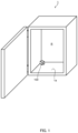
- FIG. 1 is a schematic view illustrating an example of a culture device according to an embodiment of the present disclosure
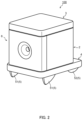
- FIG. 2 is a perspective view illustrating an example of an external appearance of an atomization device according the embodiment of the present disclosure the;
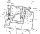
- FIG. 3 is a longitudinal sectional view of the atomization device including a liquid level detection device according the embodiment of the present disclosure, taken along a vertical plane;
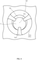
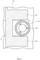
- FIG. 4 is a diagram taken along IV-IV in FIG. 3 ;
- FIG. 5 is a sectional view taken along line V-V of FIG. 3 ;
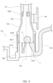
- FIG. 6 is a longitudinal sectional view illustrating a part of the liquid level detection device according the embodiment of the present disclosure, and a state where the liquid level detection device is disposed upside down;
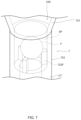
- FIG. 7 is a diagram illustrating a state where a float provided in the liquid level detection device according the embodiment of the present disclosure is placed at a lower protrusion piece.
- FIG. 1 is a schematic view illustrating an example of culture device 1 according to the present disclosure.
- culture device 1 can perform growing of plants, culture of plants cells, tissues, and organs, breeding and growing of insects and the like.
- object of culture, breeding and growing the like by the culture device 1 is simply referred to as object.
- culture device 1 When culture device 1 performs culture, breeding, growing and the like of the above-described object, culture chamber R must be kept clean. Culture device 1 performs decontamination operation of culture chamber R by performing a predetermined operation.
- Atomization device 100 is a decontamination device that is disposed in culture chamber R when culture device 1 performs the decontamination operation.
- 1 a in FIG. 1 represents a surface (i.e., installation surface) where atomization device 100 is disposed.
- Atomization device 100 stores in its inside decontamination liquid used for the decontamination operation, and in the decontaminate operation of culture device 1 , atomization device 100 emits the decontamination liquid to culture chamber R in a mist form by atomizing the decontamination liquid.
- atomization device 100 may be provided to culture device 1 .
- FIG. 2 is a perspective view illustrating an example of an external appearance of atomization device 100 .
- FIG. 3 is a longitudinal sectional view illustrating atomization device 100 including liquid level detection device 7 , taken along a vertical plane.
- FIG. 4 is a diagram taken along IV-IV in FIG. 3 .
- FIG. 5 is a sectional view taken along line V-V of FIG. 3 .
- the decontamination liquid used for the decontamination operation of culture device 1 is hydrogen peroxide solution.
- Atomization device 100 includes main body part 2 , lid 3 , supporting member 4 , leg 5 and atomization mechanism 6 .
- Main body part 2 includes liquid supplying reservoir 71 R described later, and hydrogen peroxide solution is stored in storage space SR (see FIG. 3 ), which is a space surrounded by liquid supplying reservoir 71 R.
- Depression 21 is formed in the front outer surface of main body part 2 .
- Atomization mechanism 6 is disposed in depression 21 .
- Outlet OH is formed in main body part 2 .
- Outlet OH is a through hole that is open at the bottom surface of depression 21 , and is a passage hole through which the hydrogen peroxide solution that flows out of storage space SR passes.
- Lid 3 is a member that covers main body part 2 from the upper side.
- Supporting member 4 is a member attached on the lower side of main body part 2 and supports main body part 2 .
- Legs 5 are provided at the bottom surface of supporting member 4 .
- Legs 5 include a pair of front legs 51 on the front side, and a pair of rear legs 52 on the rear side.
- the size of each of front legs 51 in the vertical direction is greater than the size of each of rear legs 52 in the vertical direction.
- atomization device 100 is disposed such that with respect to installation surface 1 a , an end portion of supporting member 4 on the front leg 51 side is located on the upper side than an end portion of supporting member 4 on the rear leg 52 side.
- the inclination angle of supporting member 4 with respect to installation surface 1 a is, for example, six degrees.
- the lower side outline of front legs 51 includes a pointed portion and a curved portion, and front legs 51 are in substantially point contact with installation surface 1 a .
- the outline of rear legs 52 on the installation surface 1 a side is curved, and rear legs 52 are in substantially point contact with installation surface 1 a.
- the contact area between front legs 51 and installation surface 1 a , and the contact area between rear legs 52 and installation surface la can be reduced as much as possible, and thus the hydrogen peroxide solution atomized by atomization device 100 can be diffused over a wide range of the region on the lower side of supporting member 4 in installation surface 1 a.
- Atomization mechanism 6 includes diaphragm 60 , holding member 61 , and nozzle 64 .
- Diaphragm 60 has a circular plate shape.
- the center portion of diaphragm 60 has a substantially dome shape protruding to the front side.
- a plurality of through holes through which hydrogen peroxide solution passes is formed at a center portion of diaphragm 60 . Note that through holes are so small that they are not visible to the naked eye.
- the center portion of diaphragm 60 vibrates back and forth under the vibration of the outer periphery portion of diaphragm 60 . When diaphragm 60 vibrates, the hydrogen peroxide solution is passed through the through holes and emitted in the form of minute droplets. That is, when diaphragm 60 vibrates, the hydrogen peroxide solution is atomized.
- the center portion of diaphragm 60 is made of metal, and is for example, made of nickel. Note that diaphragm 60 is disposed by holding member 61 such that the outer surface of diaphragm 60 faces the obliquely upper side.
- the inclination angle between central axis CL of diaphragm 60 and the horizontal surface is, for example, six degrees.
- the outer periphery portion of diaphragm 60 is made of piezoelectric ceramic.
- the outer periphery portion of diaphragm 60 vibrates back and forth by the piezoelectric effect when an AC voltage is applied from a power source (not illustrated in the drawing) provided in atomization device 100 , through an electrode.
- Holding member 61 sandwiches the outer periphery portion of diaphragm 60 from the inner surface side and the outer surface side of diaphragm 60 .
- Holding member 61 is composed of inner holding member 62 and outer holding member 63 . Note that both inner holding member 62 and outer holding member 63 are made of silicon.
- Inner holding member 62 supports the outer periphery portion of diaphragm 60 from the inner surface side.
- Supply path 62 R communicating with outlet OH is formed in inner holding member 62 , and the hydrogen peroxide solution in storage space SR is guided to diaphragm 60 through outlet OH and supply path 62 R.
- Outer holding member 63 supports the outer periphery portion of diaphragm 60 from the outer surface side. Jetting path 63 R is formed in outer holding member 63 , and the hydrogen peroxide solution atomized by diaphragm 60 passes through jetting path 63 R.
- Nozzle 64 is a member in which a jetting hole 64 H, through which the hydrogen peroxide solution past minute through holes formed in diaphragm 60 in a mist form passes, is formed.
- liquid level detection device 7 is described with reference to FIGS. 3 to 5 .
- Liquid level detection device 7 of the present embodiment is formed as a part of atomization device 100 . Note that liquid level detection device 7 may be separable from atomization device 100 .
- liquid level detection device 7 includes liquid reservoir 7 R, float F, connection tube CT, and sensor Se.
- Liquid reservoir 7 R includes liquid supplying reservoir 71 R and detecting reservoir 72 R.
- the hydrogen peroxide solution atomized by diaphragm 60 is stored in liquid supplying reservoir 71 R.
- Detecting reservoir 72 R includes upper cylindrical part 721 , lower cylindrical part 722 and tapered cylindrical part 723 .
- Lower cylindrical part 722 and tapered cylindrical part 723 are formed of a transparent material. Note that as long as at least lower cylindrical part 722 is formed of a transparent material, other portions need not necessarily be formed of a transparent material.
- TCL represents the central axis of detecting reservoir 72 R.
- Upper cylindrical part 721 is a cylindrical portion located on the upper side than lower cylindrical part 722 and tapered cylindrical part 723 .
- Upper cylindrical part 721 is composed of upper portion 721 A, lower portion 721 B, and connecting portion 721 C.
- Upper portion 721 A is a topmost portion of upper cylindrical part 721 , and is composed of the same material as liquid supplying reservoir 71 R.
- Three upper protrusion pieces 721 F protruding from the inner peripheral surface of upper portion 721 A toward central axis TCL of detecting reservoir 72 R are formed at the inner peripheral surface of upper portion 721 A (see FIG. 4 ).
- Upper protrusion piece 721 F has a substantially plate shape.
- Lower portion 721 B is a lowermost portion of upper cylindrical part 721 , and is formed integrally with tapered cylindrical part 723 and lower cylindrical part 722 .
- Connecting portion 721 C is, for example, a silicon tube, and connects between upper portion 721 A and lower portion 721 B.
- Lower cylindrical part 722 is located on the lower side than upper cylindrical part 721 .
- Detection space SP where float F can be contained inside is formed on the upper side of lower cylindrical part 722 .
- the inner diameter of lower cylindrical part 722 is smaller than the inner diameter of the upper cylindrical part, and greater than the outer diameter of float F.
- three lower protrusion pieces 722 F protruding from the inner peripheral surface of detecting reservoir 72 R toward central axis TCL of detecting reservoir 72 R are formed at the inner peripheral surface of detecting reservoir 72 R.
- lower protrusion piece 722 F has a substantially plate shape.
- Tapered cylindrical part 723 is located between upper cylindrical part 721 and lower cylindrical part 722 , and is connected to lower portion 721 B and lower cylindrical part 722 .
- the inner diameter of tapered cylindrical part 723 decreases as the distance to lower cylindrical part 722 decreases.
- the inner diameter at the upper end of tapered cylindrical part 723 is the same as the inner diameter of upper cylindrical part 721
- the inner diameter at the lower end of tapered cylindrical part 723 is the same as the inner diameter of lower cylindrical part 722 .
- Float F is disposed in detecting reservoir 72 R, and floated on the hydrogen peroxide solution in detecting reservoir 72 R.
- the height of liquid level SS and the height of float F have a relationship in which one of them is determined when the other is determined.
- Float F is composed of an opaque material.
- float F has a spherical shape.
- sensor Se is located at a position lower than upper cylindrical part 721 in a vertical direction to surround the periphery of lower cylindrical part 722 .
- Sensor Se includes light emission part Sea and light reception part Seb.
- Light emission part Sea emits detecting light toward light reception part Seb.
- the detecting light emitted by light emission part Sea passes through detection space SP of lower cylindrical part 722 and goes toward light reception part Seb.
- Light reception part Seb receives the detecting light.
- Sensor Se outputs a detection signal when light reception part Seb stops receiving the detecting light.
- the light from light emission part Sea is blocked when float F is housed in detection space SP.
- each portion of liquid supplying reservoir 71 R and detecting reservoir 72 R, the positions of sensor Se and diaphragm 60 , and the sizes of front legs 51 and rear legs 52 in the vertical direction are adjusted such that the detecting light from light emission part Sea is blocked by float F when liquid level LS reaches the predetermined position
- liquid level detection device 7 atomization device 100 , and culture device 1 during a decontamination operation are described.
- culture device 1 stops the operation of the power source of atomization device 100 . In this manner, the vibration of diaphragm 60 stops.
- culture device 1 stops the atomizing of the hydrogen peroxide solution at atomization device 100 .
- liquid level LS i.e., liquid level SS
- sensor Se When liquid level LS, i.e., liquid level SS, reaches sensor detection line SSL, the detecting light from light emission part Sea is blocked by float F, and light reception part Seb stops receiving the detecting light.
- sensor Se When light reception part Seb stops receiving the detecting light, sensor Se outputs a detection signal to culture device 1 .
- culture device 1 stops the operation of the power source of atomization device 100 to stop the vibration of diaphragm 60 .
- FIG. 6 is a longitudinal sectional view illustrating a part of the liquid level detection device as shown in FIG. 3 (a part around upper cylindrical part 721 ). Note that the liquid level detection device in FIG. 6 is disposed upside down, with central axis TCL of the detecting reservoir being perpendicular to the horizontal surface.
- FIG. 7 is a diagram illustrating a state where float F provided in the liquid level detection device as shown in FIG. 3 is placed at lower protrusion pieces 722 F. In FIG. 7 , lower cylindrical part 722 , tapered cylindrical part 723 , parts inside connection tube CT and float Fare illustrated with the broken lines.
- the user takes out atomization device 100 from culture chamber R, detaches lid 3 from main body part 2 of atomization device 100 , and tilts atomization device 100 .
- atomization device 100 is tilted, the hydrogen peroxide solution in liquid supplying reservoir 71 R, detecting reservoir 72 R and connection tube CT flows to the outside of main body part 2 .
- liquid level detection device 7 is brought into a state where float F is placed at the bottom surface of upper protrusion pieces 721 F as illustrated in FIG. 6 . Since twice the distance from the central axis TCL side end of upper protrusion pieces 721 F to central axis TCL is smaller than the outer diameter of float F, float F does not move to the upper side (in FIG. 6 , the lower side) than the bottom surface of upper protrusion pieces 721 F. That is, when float F is located on the uppermost side, float F is in contact with the bottom surface of upper protrusion pieces 721 F (see FIG. 6 ), and float F does not fit to the upper end portion of detecting reservoir 72 R, i.e., a portion between upper protrusion pieces 721 F.
- liquid level detection device 7 is set to a state where float F is placed at the top surface of lower protrusion pieces 722 F. Since twice the distance from the central axis TCL side end of lower protrusion pieces 722 F to central axis TCL is smaller than the outer diameter of float F, float F does not move to the lower side than the top surface of lower protrusion pieces 722 F.
- float F is disposed inside detecting reservoir 72 R where the decontamination liquid is stored, and the fact that the liquid level of the decontamination liquid in liquid supplying reservoir 71 R has reached the predetermined position is detected by using float F. In this manner, the liquid level position of the decontamination liquid in atomization device 100 , which is the decontamination device used for the decontamination of culture device 1 , can be correctly detected.
- liquid level detection device 7 of the present embodiment does not require a special light-emitting sensor, and therefore can be manufactured at lower cost.
- the vibration of diaphragm 60 can be stopped, with the lower half of the inner surface of at least the center portion of diaphragm 60 immersed in the decontamination liquid. In this manner, it is possible to prevent damage to diaphragm 60 due to the vibration with the region smaller than half the inner surface of the center portion of diaphragm 60 immersed in the decontamination liquid, or with the entire diaphragm 60 not immersed in the decontamination liquid. Note that it suffices that the predetermined position is set to the position on the upper side than the center of diaphragm 60 in the vertical direction.
- the outer diameter of float F is sufficiently smaller than the inner diameter of upper cylindrical part 721 .
- the decontamination liquid does not form an annular bridge at a location between float F and upper cylindrical part 721 and a location higher than the liquid level of the decontamination liquid in the vertical direction. That is, float F does not adhere to the inner surface of upper cylindrical part 721 on the upper side than the liquid level. In this manner, float Fis smoothly lowered in upper cylindrical part 721 as the liquid level is lowered.
- liquid level detection device 7 can reliably detect the liquid level position of the decontamination liquid in liquid supplying reservoir 71 R.
- the inner diameter of lower cylindrical part 722 is smaller than the inner diameter of upper cylindrical part 721 , the amount of decontamination liquid remaining inside liquid level detection device 7 when the decontamination operation is completed can be reduced. Since the decontamination liquid remaining inside liquid level detection device 7 is discarded, the discarded decontamination liquid can be reduced by using liquid level detection device 7 of the present embodiment as atomization device 100 . Thus, a decontamination operation using a smaller amount of decontamination liquid can be performed.
- outer diameter of lower cylindrical part 722 is smaller than the outer diameter of upper cylindrical part 721 , a space for disposing sensor Se can be ensured at lower cylindrical part 722 disposed below upper cylindrical part 721 .
- Detecting reservoir 72 R includes tapered cylindrical part 723 connected to upper cylindrical part and lower cylindrical part 722 whose inner diameter is smaller than upper cylindrical part 721 , and the inner diameter of tapered cylindrical part 723 decreases as the distance to lower cylindrical part 722 decreases.
- float F is smoothly guided to detection space SP without interfering with the downward movement of float F at the boundary between upper cylindrical part 721 and lower cylindrical part 722 .
- the liquid level of the decontamination liquid in liquid supplying reservoir 71 R can be reliably detected.
- Upper protrusion pieces 721 F are formed in the inner peripheral surface of upper cylindrical part 721 , and twice the distance from the central axis TCL side end of upper protrusion pieces 721 F to central axis TCL is smaller than the outer diameter of float F, and thus float F does not fit to a portion between upper protrusion pieces 721 F.
- the width size of the bottom surface of upper protrusion pieces 721 F is small, and therefore, when liquid level detection device 7 is temporarily disposed upside down to discard the decontamination liquid remaining in liquid level detection device 7 as illustrated in FIG. 6 , the amount of decontamination liquid that can remain between the outer peripheral surface of float F and the bottom surface of upper protrusion pieces 721 F is small.
- a plurality of lower protrusion pieces 722 F protruding toward central axis TCL of detecting reservoir 72 R is formed at the inner peripheral surface of lower cylindrical part 722 , and float F is in contact with the top surface of each of lower protrusion pieces 722 F when float Fis located on the lowermost side (see FIG. 7 ). In this manner, float F does not fit to the upper end of the tube (i.e., connection tube CT) connected with lower cylindrical part 722 and having an inner diameter smaller than lower cylindrical part 722 .
- the air flows to liquid supplying reservoir 71 R from the gap between air lower protrusion pieces 722 F through connection tube CT even with float F in contact with each of lower protrusion pieces 722 F when the decontamination liquid remaining inside liquid level detection device 7 is discarded. In this manner, the decontamination liquid can be discarded without leaving it in connection tube CT or inside detecting reservoir 72 R.
- upper protrusion pieces 721 F limits the upward movement of float F, and that at least a part of upper protrusion pieces 721 F is located inside detecting reservoir 72 R.
- upper protrusion piece 721 F has a shape with a smaller contact area with float F. In this manner, upper protrusion pieces 721 F may not protrude toward central axis TCL of detecting reservoir 72 R, and any number of upper protrusion pieces 721 F may be provided. In addition, upper protrusion pieces 721 F may not be formed inside detecting reservoir 72 R.
- each of upper protrusion pieces 721 F may have a straight and round rod shape. One end and the other end of each of upper protrusion pieces 721 F may be connected to the inner peripheral surface of upper cylindrical part 721 so that it does not pass through central axis TCL of detecting reservoir 72 R. In addition, one end of each of upper protrusion pieces 721 F may be connected at a predetermined position outside detecting reservoir 72 R, and the other end of each of upper protrusion pieces 721 F may extend toward central axis TCL of detecting reservoir 72 R inside detecting reservoir 72 R.
- each of lower protrusion pieces 722 F limits the downward movement of float F, and that each of lower protrusion pieces 722 F is formed at the inner peripheral surface of lower cylindrical part 722 .
- each of lower protrusion pieces 722 F has a shape with a smaller contact area with float F. In this manner, lower protrusion pieces 722 F may not protrude toward central axis TCL of detecting reservoir 72 R, and any number of lower protrusion pieces 722 F may be provided.
- each of lower protrusion pieces 722 F may have a straight and round rod shape. One end and the other end of each of lower protrusion pieces 722 F may be connected to the inner peripheral surface of lower cylindrical part 722 so that it does not pass through central axis TCL of detecting reservoir 72 R.
- liquid reservoir 7 R is separated into liquid supplying reservoir 71 R and detecting reservoir 72 R in the above-described embodiment, liquid reservoir 7 R may include only one reservoir, and the reservoir may have the functions of liquid supplying reservoir 71 R and detecting reservoir 72 R. In this case, liquid level detection device 7 does not include connection tube CT.
- liquid level detection device 7 of the above-described embodiment detects whether the liquid level of the decontamination liquid has reached a predetermined position by using float F, the liquid level position of the decontamination liquid may be detected at all times.
- the liquid level detection device is applicable to atomization devices used for decontamination operations of culture devices. Therefore, its industrial applicability is wide.
Landscapes
- Health & Medical Sciences (AREA)
- Life Sciences & Earth Sciences (AREA)
- Fluid Mechanics (AREA)
- General Physics & Mathematics (AREA)
- Physics & Mathematics (AREA)
- Engineering & Computer Science (AREA)
- Chemical & Material Sciences (AREA)
- Wood Science & Technology (AREA)
- Zoology (AREA)
- Bioinformatics & Cheminformatics (AREA)
- Organic Chemistry (AREA)
- Biomedical Technology (AREA)
- General Health & Medical Sciences (AREA)
- Virology (AREA)
- Biochemistry (AREA)
- Cell Biology (AREA)
- Genetics & Genomics (AREA)
- General Engineering & Computer Science (AREA)
- Biotechnology (AREA)
- Microbiology (AREA)
- Sustainable Development (AREA)
- General Chemical & Material Sciences (AREA)
- Veterinary Medicine (AREA)
- Epidemiology (AREA)
- Animal Behavior & Ethology (AREA)
- Public Health (AREA)
- Chemical Kinetics & Catalysis (AREA)
- Level Indicators Using A Float (AREA)
- Apparatus For Disinfection Or Sterilisation (AREA)
- Special Spraying Apparatus (AREA)
- Spray Control Apparatus (AREA)
- Coating Apparatus (AREA)
- Apparatus Associated With Microorganisms And Enzymes (AREA)
Applications Claiming Priority (3)
| Application Number | Priority Date | Filing Date | Title |
|---|---|---|---|
| JP2019-197497 | 2019-10-30 | ||
| JP2019197497 | 2019-10-30 | ||
| PCT/JP2020/038226 WO2021085076A1 (ja) | 2019-10-30 | 2020-10-09 | 液面検出装置、噴霧装置、および培養装置 |
Related Parent Applications (1)
| Application Number | Title | Priority Date | Filing Date |
|---|---|---|---|
| PCT/JP2020/038226 Continuation WO2021085076A1 (ja) | 2019-10-30 | 2020-10-09 | 液面検出装置、噴霧装置、および培養装置 |
Publications (2)
| Publication Number | Publication Date |
|---|---|
| US20220252445A1 US20220252445A1 (en) | 2022-08-11 |
| US12158366B2 true US12158366B2 (en) | 2024-12-03 |
Family
ID=75715159
Family Applications (1)
| Application Number | Title | Priority Date | Filing Date |
|---|---|---|---|
| US17/724,109 Active 2041-09-26 US12158366B2 (en) | 2019-10-30 | 2022-04-19 | Liquid surface detection device, atomization device, and culture device |
Country Status (5)
| Country | Link |
|---|---|
| US (1) | US12158366B2 (https=) |
| EP (1) | EP4036535B1 (https=) |
| JP (1) | JP7538811B2 (https=) |
| CN (1) | CN114599943B (https=) |
| WO (1) | WO2021085076A1 (https=) |
Families Citing this family (1)
| Publication number | Priority date | Publication date | Assignee | Title |
|---|---|---|---|---|
| CN215062598U (zh) * | 2021-05-13 | 2021-12-07 | 中山市斯泰尔电器科技有限公司 | 一种新型聚能装置及超声波加湿器 |
Citations (10)
| Publication number | Priority date | Publication date | Assignee | Title |
|---|---|---|---|---|
| JPH0763596A (ja) | 1993-08-27 | 1995-03-10 | Fujita Corp | 液面検知装置 |
| DE19608866A1 (de) | 1996-03-07 | 1997-09-11 | Eaton Gmbh | Meßvorrichtung für den Flüssigkeitspegel in einem Behälter, insbesondere in einer Wasch- oder Geschirrspülmaschine |
| JPH10262896A (ja) | 1997-03-26 | 1998-10-06 | Zojirushi Corp | 食器洗い機 |
| JP3883654B2 (ja) * | 1997-07-16 | 2007-02-21 | 株式会社ダスキン | 脱臭・消臭・殺菌装置 |
| JP2008036394A (ja) | 2006-07-14 | 2008-02-21 | Matsushita Electric Ind Co Ltd | 霧化装置および同装置を備えた食器洗い機 |
| US20090000317A1 (en) * | 2007-03-29 | 2009-01-01 | Joachim Schill | Device and method for disinfection of ice machines, ice silos and/or chutes for transport of ice |
| JP2010249337A (ja) | 2009-04-13 | 2010-11-04 | Sanyo Electric Co Ltd | 超音波霧化装置 |
| JP2011036771A (ja) | 2009-08-07 | 2011-02-24 | Honda Electronic Co Ltd | 超音波霧化装置及び霧化用振動子 |
| JP2011136035A (ja) | 2009-12-28 | 2011-07-14 | Kawasaki Heavy Ind Ltd | 滅菌液霧化発生装置および滅菌処理方法 |
| JP2012087968A (ja) | 2010-10-18 | 2012-05-10 | Toshiba Corp | 家電機器 |
Family Cites Families (6)
| Publication number | Priority date | Publication date | Assignee | Title |
|---|---|---|---|---|
| JPH01107892A (ja) * | 1987-10-22 | 1989-04-25 | Toshiba Heating Appliances Co | 飲料水の製造装置 |
| JPH01111485A (ja) * | 1987-10-23 | 1989-04-28 | Toshiba Heating Appliances Co | 飲料水の製造装置 |
| CN2685848Y (zh) * | 2004-02-20 | 2005-03-16 | 中山市美扬电器有限公司 | 一种水位检测装置 |
| CN202420625U (zh) * | 2011-12-15 | 2012-09-05 | 中牟县供电公司 | 一种变压器油位指示器 |
| JP2015034706A (ja) * | 2013-08-07 | 2015-02-19 | スタンレー電気株式会社 | 液量表示装置 |
| JP2019197497A (ja) | 2018-05-11 | 2019-11-14 | Necパーソナルコンピュータ株式会社 | ヘッドマウントディスプレイシステム、通知制御装置、通知制御方法、及びプログラム |
-
2020
- 2020-10-09 CN CN202080074379.4A patent/CN114599943B/zh active Active
- 2020-10-09 WO PCT/JP2020/038226 patent/WO2021085076A1/ja not_active Ceased
- 2020-10-09 JP JP2021554267A patent/JP7538811B2/ja active Active
- 2020-10-09 EP EP20881080.4A patent/EP4036535B1/en active Active
-
2022
- 2022-04-19 US US17/724,109 patent/US12158366B2/en active Active
Patent Citations (10)
| Publication number | Priority date | Publication date | Assignee | Title |
|---|---|---|---|---|
| JPH0763596A (ja) | 1993-08-27 | 1995-03-10 | Fujita Corp | 液面検知装置 |
| DE19608866A1 (de) | 1996-03-07 | 1997-09-11 | Eaton Gmbh | Meßvorrichtung für den Flüssigkeitspegel in einem Behälter, insbesondere in einer Wasch- oder Geschirrspülmaschine |
| JPH10262896A (ja) | 1997-03-26 | 1998-10-06 | Zojirushi Corp | 食器洗い機 |
| JP3883654B2 (ja) * | 1997-07-16 | 2007-02-21 | 株式会社ダスキン | 脱臭・消臭・殺菌装置 |
| JP2008036394A (ja) | 2006-07-14 | 2008-02-21 | Matsushita Electric Ind Co Ltd | 霧化装置および同装置を備えた食器洗い機 |
| US20090000317A1 (en) * | 2007-03-29 | 2009-01-01 | Joachim Schill | Device and method for disinfection of ice machines, ice silos and/or chutes for transport of ice |
| JP2010249337A (ja) | 2009-04-13 | 2010-11-04 | Sanyo Electric Co Ltd | 超音波霧化装置 |
| JP2011036771A (ja) | 2009-08-07 | 2011-02-24 | Honda Electronic Co Ltd | 超音波霧化装置及び霧化用振動子 |
| JP2011136035A (ja) | 2009-12-28 | 2011-07-14 | Kawasaki Heavy Ind Ltd | 滅菌液霧化発生装置および滅菌処理方法 |
| JP2012087968A (ja) | 2010-10-18 | 2012-05-10 | Toshiba Corp | 家電機器 |
Non-Patent Citations (2)
| Title |
|---|
| Extended European Search Report dated Oct. 21, 2022 issued in the corresponding European Patent Application No. 20881080.4. |
| International Search Report dated Dec. 28, 2020 issued in International Patent Application No. PCT/JP2020/038226, with English translation. |
Also Published As
| Publication number | Publication date |
|---|---|
| EP4036535A1 (en) | 2022-08-03 |
| WO2021085076A1 (ja) | 2021-05-06 |
| CN114599943B (zh) | 2025-10-10 |
| US20220252445A1 (en) | 2022-08-11 |
| JP7538811B2 (ja) | 2024-08-22 |
| CN114599943A (zh) | 2022-06-07 |
| EP4036535A4 (en) | 2022-11-23 |
| JPWO2021085076A1 (https=) | 2021-05-06 |
| EP4036535B1 (en) | 2023-12-06 |
Similar Documents
| Publication | Publication Date | Title |
|---|---|---|
| US8333187B2 (en) | Aerosol generating means for inhalation therapy devices | |
| US12158366B2 (en) | Liquid surface detection device, atomization device, and culture device | |
| ES2532224T3 (es) | Dispositivo de dispensación de autodetección | |
| US12371648B2 (en) | Atomization device and culture device | |
| US20100308132A1 (en) | Nebulising device for liquid substances | |
| TWI636964B (zh) | 可攜式淨化裝置 | |
| KR102221824B1 (ko) | 근접 센서를 구비하는 소독제 자동 분사 장치 | |
| JP2022003298A (ja) | 加湿器 | |
| CN108298636B (zh) | 可携式净化装置 | |
| EP2388076B1 (en) | Watertight fragrance dispensing device | |
| CN101804245A (zh) | 美容装置 | |
| KR20180072236A (ko) | 수조통과 가습조가 일체형 구조를 갖는 가습기 | |
| JPWO2021085075A5 (ja) | 噴霧装置および培養装置 | |
| CN114222593A (zh) | 液体喷雾装置 | |
| JP2007203225A (ja) | 薬剤霧化器 | |
| KR200482735Y1 (ko) | 간편 세척 초음파 가습기 | |
| JP2012198755A (ja) | 加煙試験器 | |
| JP7133077B1 (ja) | 噴霧装置及び走行玩具 | |
| KR20230075931A (ko) | 버튼셀 세정용 트레이 | |
| JP4672698B2 (ja) | 粒状体取出装置 | |
| CN112010398B (zh) | 容器 | |
| JP4292500B2 (ja) | 遊技機 | |
| JP2024089187A (ja) | 液体分注装置 | |
| JP7465061B2 (ja) | 薬液供給装置 | |
| JP2022129200A (ja) | 消毒液噴霧装置 |
Legal Events
| Date | Code | Title | Description |
|---|---|---|---|
| AS | Assignment |
Owner name: PHC HOLDINGS CORPORATION, JAPAN Free format text: ASSIGNMENT OF ASSIGNORS INTEREST;ASSIGNORS:SAKAI, YUTA;YOSHIDA, MASAKI;HONDA, KOUSUKE;AND OTHERS;SIGNING DATES FROM 20220315 TO 20220324;REEL/FRAME:059639/0705 |
|
| FEPP | Fee payment procedure |
Free format text: ENTITY STATUS SET TO UNDISCOUNTED (ORIGINAL EVENT CODE: BIG.); ENTITY STATUS OF PATENT OWNER: LARGE ENTITY |
|
| STPP | Information on status: patent application and granting procedure in general |
Free format text: DOCKETED NEW CASE - READY FOR EXAMINATION |
|
| STPP | Information on status: patent application and granting procedure in general |
Free format text: NON FINAL ACTION MAILED |
|
| STPP | Information on status: patent application and granting procedure in general |
Free format text: RESPONSE TO NON-FINAL OFFICE ACTION ENTERED AND FORWARDED TO EXAMINER |
|
| STPP | Information on status: patent application and granting procedure in general |
Free format text: NOTICE OF ALLOWANCE MAILED -- APPLICATION RECEIVED IN OFFICE OF PUBLICATIONS |
|
| STCF | Information on status: patent grant |
Free format text: PATENTED CASE |