US11846292B2 - Method for determining the operating point - Google Patents
Method for determining the operating point Download PDFInfo
- Publication number
- US11846292B2 US11846292B2 US16/970,684 US201916970684A US11846292B2 US 11846292 B2 US11846292 B2 US 11846292B2 US 201916970684 A US201916970684 A US 201916970684A US 11846292 B2 US11846292 B2 US 11846292B2
- Authority
- US
- United States
- Prior art keywords
- domain
- startup
- rotation
- operating point
- points
- Prior art date
- Legal status (The legal status is an assumption and is not a legal conclusion. Google has not performed a legal analysis and makes no representation as to the accuracy of the status listed.)
- Active, expires
Links
- 238000000034 method Methods 0.000 title claims abstract description 36
- 238000010586 diagram Methods 0.000 claims description 15
- 230000008569 process Effects 0.000 description 4
- 230000003247 decreasing effect Effects 0.000 description 2
- 230000001419 dependent effect Effects 0.000 description 2
- 238000013461 design Methods 0.000 description 2
- 230000008901 benefit Effects 0.000 description 1
- 238000009530 blood pressure measurement Methods 0.000 description 1
- 230000008859 change Effects 0.000 description 1
- 238000005259 measurement Methods 0.000 description 1
- 230000004048 modification Effects 0.000 description 1
- 238000012986 modification Methods 0.000 description 1
- 238000012360 testing method Methods 0.000 description 1
Images


Classifications
-
- F—MECHANICAL ENGINEERING; LIGHTING; HEATING; WEAPONS; BLASTING
- F04—POSITIVE - DISPLACEMENT MACHINES FOR LIQUIDS; PUMPS FOR LIQUIDS OR ELASTIC FLUIDS
- F04D—NON-POSITIVE-DISPLACEMENT PUMPS
- F04D25/00—Pumping installations or systems
- F04D25/02—Units comprising pumps and their driving means
- F04D25/06—Units comprising pumps and their driving means the pump being electrically driven
-
- F—MECHANICAL ENGINEERING; LIGHTING; HEATING; WEAPONS; BLASTING
- F04—POSITIVE - DISPLACEMENT MACHINES FOR LIQUIDS; PUMPS FOR LIQUIDS OR ELASTIC FLUIDS
- F04D—NON-POSITIVE-DISPLACEMENT PUMPS
- F04D25/00—Pumping installations or systems
- F04D25/02—Units comprising pumps and their driving means
- F04D25/08—Units comprising pumps and their driving means the working fluid being air, e.g. for ventilation
-
- F—MECHANICAL ENGINEERING; LIGHTING; HEATING; WEAPONS; BLASTING
- F04—POSITIVE - DISPLACEMENT MACHINES FOR LIQUIDS; PUMPS FOR LIQUIDS OR ELASTIC FLUIDS
- F04D—NON-POSITIVE-DISPLACEMENT PUMPS
- F04D27/00—Control, e.g. regulation, of pumps, pumping installations or pumping systems specially adapted for elastic fluids
- F04D27/004—Control, e.g. regulation, of pumps, pumping installations or pumping systems specially adapted for elastic fluids by varying driving speed
-
- Y—GENERAL TAGGING OF NEW TECHNOLOGICAL DEVELOPMENTS; GENERAL TAGGING OF CROSS-SECTIONAL TECHNOLOGIES SPANNING OVER SEVERAL SECTIONS OF THE IPC; TECHNICAL SUBJECTS COVERED BY FORMER USPC CROSS-REFERENCE ART COLLECTIONS [XRACs] AND DIGESTS
- Y02—TECHNOLOGIES OR APPLICATIONS FOR MITIGATION OR ADAPTATION AGAINST CLIMATE CHANGE
- Y02B—CLIMATE CHANGE MITIGATION TECHNOLOGIES RELATED TO BUILDINGS, e.g. HOUSING, HOUSE APPLIANCES OR RELATED END-USER APPLICATIONS
- Y02B30/00—Energy efficient heating, ventilation or air conditioning [HVAC]
- Y02B30/70—Efficient control or regulation technologies, e.g. for control of refrigerant flow, motor or heating
Definitions
- the invention relates to a method for determining the operating point of a fan. More particularly, the invention relates to a method for determining the operating point of a fan when a clear correlation between the speed, the performance, and the volumetric flow rate of the fan is not possible.
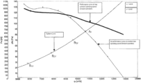
- the “fan curve” illustrates the dependent relationship between volumetric flow rate and pressure increase.
- the progression of the fan curve is dependent on the design of the fan.
- Fan curves are typically measured and recorded on a fan test rig suitable for this purpose. It is important to note, however, that these curves have typically been measured under ideal conditions on individual, free-standing representative blowers of a fan model series, with an unobstructed flow. Actual curves under installed conditions may deviate from these.
- the system curve represents the flow resistance of a system, against which the fan must operate.
- the operating point of a fan which is used in a practical application, is the point at which fan curve and system curve intersect.
- the operating point can be determined as soon as the motor parameters are established, since the operating point is located at only one possible point at which fan curve and system curve intersect (operating point). If the correlation is unclear, the fan could theoretically be at several operating points after the motor parameters are established, since no information about the volumetric flow rate is available. It is unclear which of the operating points that might be, because without a sensor, only the motor parameters can be measured and verified.
- the volumetric flow rate For practical applications, it is necessary to ascertain the volumetric flow rate and thus the operating point of a fan.
- sensor-based methods are available, which are capable of approximating the volumetric flow rate of the fan.
- One widely used method for determining the volumetric flow rate for example, is the differential pressure measurement method. Using pressure tap ports, pressure hoses, and a pressure sensor, the differential pressure between the intake nozzle of the fan and a reference point in the system can be determined. The measured pressure difference is proportional to the product of air density and the square of the volumetric flow rate. This can in turn be used to determine the volumetric flow rate of the fan in its installed state in the system. Once the volumetric flow rate in a practical application has been ascertained, the operating point can be determined using a set of characteristic fan curves, measured previously.
- EP 2 508 811 B1 is a device for determining the volumetric flow rate transported by a fan, which device is provided in the region of an inlet nozzle of the fan, along with a differential pressure sensor for connecting a measurement opening to a reference tube.
- An objective of the present disclosure is to propose a universally applicable method for determining the operating point of a fan, more particularly a method for determining the operating point of a fan when a clear correlation between the speed, the performance, and the volumetric flow rate of the fan is not possible.
- This objective is achieved by the combination of the following features in a method for determining the operating point of an electric motor-driven fan in a system.
- This method generally comprises at least one startup of the fan, wherein based on motor parameters of the fan, an operating point A of the fan is determined from the at least one startup.
- FIG. 1 is a flow chart of a process sequence according to the teachings of the present disclosure
- FIG. 2 is another flow chart of a process sequence according to the teachings of the present disclosure
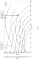
- FIG. 3 to FIG. 11 are diagrams showing characteristic curves of a fan under different conditions
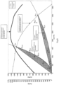
- FIG. 12 is a set of characteristic fan curves with technical flow parameters and motor parameters during forward operation according to teachings of the present disclosure.
- FIG. 13 is a set of characteristic fan curves with technical flow parameters and motor parameters during reverse operation according to the teachings of the present disclosure.
- a fundamental concept of the present disclosure involves the provision of a universal solution for different fan designs, in which the operating point A is determined based on motor parameters M by means of startups.
- a method for determining the operating point of an electric motor-driven fan in a system comprising at least one startup of the fan. Based on motor parameters M (e.g. speed, performance, current, torque) of the fan, the operating point of the fan can be determined from at least one of these startups. During the startup, the motor parameters Mi at multiple speeds are measured. From these parameters, the technical flow parameters P (e.g. volumetric flow rate, pressure) are determined, preferably from measured characteristic curves for the fan consisting of technical flow parameters and motor parameters, or by applying the relevant fan laws.
- motor parameters M e.g. speed, performance, current, torque
- the technical flow parameters P e.g. volumetric flow rate, pressure
- a forward-rotation startup or a reverse-rotation startup may be carried out to determine the operating point.
- two startups may be required to determine the operating point.
- the sequence of the startups is of no importance.
- the direction of rotation may be obtained from the specifications for the fan and corresponds to the direction of rotation during operation.
- the operating point can be determined as A v .
- the operating point can be determined as A v .
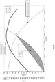
- a first domain D 1 and a second domain D 2 are defined in the characteristic curve diagram for the fan, each domain being bound by two polynomial functions (e.g. by a parabola through the origin and a straight line through the origin), which intersect at the two possible operating points A 1,v and A 2,v , respectively, during forward operation of the fan.
- the operating point is determined as A 1,v .
- the operating point A 2,V is determined to be the operating point.
- FIG. 1 a flow chart illustrating the process sequence of the method for determining the operating point of the fan is provided.
- FIG. 2 another flow chart illustrating the process sequence of the method for determining the operating point of the fan based on an exemplary embodiment is provided.
- FIG. 4 A similar diagram is shown in FIG. 4 for a first exemplary embodiment.
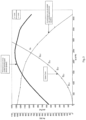
- FIG. 6 a diagram is provided that illustrates various characteristic curves of an exemplary fan, an operating point Av during forward rotation, and a domain bounded by two polynomials, e.g. a line through the origin and a parabola through the origin.
- an exemplary set of characteristic fan curves is provided with technical flow parameters and motor parameters during forward operation, plotted over volumetric flow rate, pressure, and performance.
- an exemplary set of characteristic fan curves is provided with technical flow parameters and motor parameters during reverse operation, plotted over volumetric flow rate, pressure, and performance.
Landscapes
- Engineering & Computer Science (AREA)
- Mechanical Engineering (AREA)
- General Engineering & Computer Science (AREA)
- Control Of Positive-Displacement Air Blowers (AREA)
Applications Claiming Priority (3)
| Application Number | Priority Date | Filing Date | Title |
|---|---|---|---|
| DE102018104394.5 | 2018-02-27 | ||
| DE102018104394.5A DE102018104394A1 (de) | 2018-02-27 | 2018-02-27 | Arbeitspunktbestimmung |
| PCT/EP2019/054769 WO2019166448A1 (de) | 2018-02-27 | 2019-02-26 | Arbeitspunktbestimmung |
Publications (2)
| Publication Number | Publication Date |
|---|---|
| US20200378392A1 US20200378392A1 (en) | 2020-12-03 |
| US11846292B2 true US11846292B2 (en) | 2023-12-19 |
Family
ID=65685312
Family Applications (1)
| Application Number | Title | Priority Date | Filing Date |
|---|---|---|---|
| US16/970,684 Active 2040-02-09 US11846292B2 (en) | 2018-02-27 | 2019-02-26 | Method for determining the operating point |
Country Status (5)
| Country | Link |
|---|---|
| US (1) | US11846292B2 (de) |
| EP (1) | EP3707387B1 (de) |
| CN (1) | CN111656018B (de) |
| DE (1) | DE102018104394A1 (de) |
| WO (1) | WO2019166448A1 (de) |
Families Citing this family (1)
| Publication number | Priority date | Publication date | Assignee | Title |
|---|---|---|---|---|
| DE102020118251A1 (de) * | 2020-07-10 | 2022-01-13 | Ebm-Papst Mulfingen Gmbh & Co. Kg | Verfahren und Ventilatorsystem zur Ermittlung des Zustands eines Filters in einer Ventilatoreinheit |
Citations (16)
| Publication number | Priority date | Publication date | Assignee | Title |
|---|---|---|---|---|
| DE2502444A1 (de) | 1974-12-18 | 1976-06-24 | Bbc Brown Boveri & Cie | Verfahren und einrichtung zum anfahren eines geblaeses |
| DE19506790A1 (de) | 1994-02-28 | 1995-09-21 | Kuehnle Kopp Kausch Ag | Verfahren zum wirkungsgradoptimierten Betreiben eines Radialverdichters |
| US5743715A (en) | 1995-10-20 | 1998-04-28 | Compressor Controls Corporation | Method and apparatus for load balancing among multiple compressors |
| DE19726547A1 (de) | 1997-06-23 | 1999-01-28 | Babcock Bsh Gmbh | Verfahren zur Bestimmung des Betriebspunktes eines Ventilators und Ventilator |
| DE10154783A1 (de) | 2001-11-08 | 2003-05-22 | Buderus Heiztechnik Gmbh | Verfahren zur Überwachung des Luftvolumenstromes bei einem Gebläse |
| US20090180897A1 (en) | 2008-01-15 | 2009-07-16 | Asia Vital Components Co., Ltd. | Fan enabling increased wind pressure and air volume |
| US20110200454A1 (en) | 2010-02-10 | 2011-08-18 | Abb Oy | Method in connection with a pump driven with a frequency converter and frequency converter |
| DE102011106962A1 (de) | 2010-07-08 | 2012-02-23 | Johnson Electric S.A. | Gebläse |
| CN102439318A (zh) | 2009-05-20 | 2012-05-02 | Ksb股份公司 | 用于确定做功机械的工作点的方法和装置 |
| US20120251340A1 (en) * | 2011-03-29 | 2012-10-04 | Abb Oy | Method for improving sensorless flow rate estimation accuracy of pump driven with frequency converter |
| EP2508811A1 (de) | 2011-04-08 | 2012-10-10 | Zehnder Verkaufs- und Verwaltungs AG | Vorrichtung zur Ermittlung des von einem Ventilator transportierten Volumenstroms |
| US20130015251A1 (en) * | 2011-07-12 | 2013-01-17 | Ctb, Inc. | Bin aeration system |
| WO2013052517A2 (en) | 2011-10-07 | 2013-04-11 | Honeywell International Inc. | System and method of calibration in a powered air purifying respirator |
| CN103452883A (zh) | 2012-05-31 | 2013-12-18 | 中山大洋电机股份有限公司 | 一种变速风机系统及其控制方法 |
| WO2015058945A1 (de) | 2013-10-23 | 2015-04-30 | Güntner Gmbh & Co. Kg | Verfahren zur ansteuerung eines motors eines ventilators eines wärmeaustauschers, ansteuervorrichtung für einen ventilator und wärmeaustauscher |
| CN104791281A (zh) | 2015-04-17 | 2015-07-22 | 国网智能电网研究院 | 一种电力电子功率柜内风机控制装置及控制方法 |
Family Cites Families (9)
| Publication number | Priority date | Publication date | Assignee | Title |
|---|---|---|---|---|
| EP1039139B1 (de) | 1999-03-23 | 2004-05-26 | ebm-papst Mulfingen GmbH & Co.KG | Gebläse mit vorgegebener Kennlinie |
| DE10035829C2 (de) | 1999-08-14 | 2002-07-18 | Ziehl Abegg Gmbh & Co Kg | Verfahren zum Betreiben einer Lüftungseinrichtung sowie Lüftungseinrichtung |
| US6591697B2 (en) | 2001-04-11 | 2003-07-15 | Oakley Henyan | Method for determining pump flow rates using motor torque measurements |
| SE0103371D0 (sv) | 2001-10-09 | 2001-10-09 | Abb Ab | Flow measurements |
| DE102008029910C5 (de) | 2008-06-24 | 2020-03-05 | BSH Hausgeräte GmbH | Verfahren zur Lastzustandserkennung einer Pumpe |
| DE102012006444A1 (de) | 2012-03-30 | 2013-10-02 | Wilo Se | Verfahren zum Betreiben eines Pumpenaggregats |
| ES2643743T3 (es) | 2013-04-30 | 2017-11-24 | Gidelmar, S.A. | Método y sistema de ajuste automático del funcionamiento de un ventilador, y programa de ordenador que implementa el método |
| DE102014008716B4 (de) | 2014-06-18 | 2022-01-13 | Wilo Se | Verfahren zur Erkennung eines Trockenlaufs |
| CN108331777B (zh) | 2017-01-20 | 2021-04-30 | 德昌电机(深圳)有限公司 | 电机风扇装置、空气流动性调节设备及风量控制方法 |
-
2018
- 2018-02-27 DE DE102018104394.5A patent/DE102018104394A1/de active Pending
-
2019
- 2019-02-26 WO PCT/EP2019/054769 patent/WO2019166448A1/de not_active Ceased
- 2019-02-26 US US16/970,684 patent/US11846292B2/en active Active
- 2019-02-26 CN CN201980008266.1A patent/CN111656018B/zh active Active
- 2019-02-26 EP EP19708984.0A patent/EP3707387B1/de active Active
Patent Citations (16)
| Publication number | Priority date | Publication date | Assignee | Title |
|---|---|---|---|---|
| DE2502444A1 (de) | 1974-12-18 | 1976-06-24 | Bbc Brown Boveri & Cie | Verfahren und einrichtung zum anfahren eines geblaeses |
| DE19506790A1 (de) | 1994-02-28 | 1995-09-21 | Kuehnle Kopp Kausch Ag | Verfahren zum wirkungsgradoptimierten Betreiben eines Radialverdichters |
| US5743715A (en) | 1995-10-20 | 1998-04-28 | Compressor Controls Corporation | Method and apparatus for load balancing among multiple compressors |
| DE19726547A1 (de) | 1997-06-23 | 1999-01-28 | Babcock Bsh Gmbh | Verfahren zur Bestimmung des Betriebspunktes eines Ventilators und Ventilator |
| DE10154783A1 (de) | 2001-11-08 | 2003-05-22 | Buderus Heiztechnik Gmbh | Verfahren zur Überwachung des Luftvolumenstromes bei einem Gebläse |
| US20090180897A1 (en) | 2008-01-15 | 2009-07-16 | Asia Vital Components Co., Ltd. | Fan enabling increased wind pressure and air volume |
| CN102439318A (zh) | 2009-05-20 | 2012-05-02 | Ksb股份公司 | 用于确定做功机械的工作点的方法和装置 |
| US20110200454A1 (en) | 2010-02-10 | 2011-08-18 | Abb Oy | Method in connection with a pump driven with a frequency converter and frequency converter |
| DE102011106962A1 (de) | 2010-07-08 | 2012-02-23 | Johnson Electric S.A. | Gebläse |
| US20120251340A1 (en) * | 2011-03-29 | 2012-10-04 | Abb Oy | Method for improving sensorless flow rate estimation accuracy of pump driven with frequency converter |
| EP2508811A1 (de) | 2011-04-08 | 2012-10-10 | Zehnder Verkaufs- und Verwaltungs AG | Vorrichtung zur Ermittlung des von einem Ventilator transportierten Volumenstroms |
| US20130015251A1 (en) * | 2011-07-12 | 2013-01-17 | Ctb, Inc. | Bin aeration system |
| WO2013052517A2 (en) | 2011-10-07 | 2013-04-11 | Honeywell International Inc. | System and method of calibration in a powered air purifying respirator |
| CN103452883A (zh) | 2012-05-31 | 2013-12-18 | 中山大洋电机股份有限公司 | 一种变速风机系统及其控制方法 |
| WO2015058945A1 (de) | 2013-10-23 | 2015-04-30 | Güntner Gmbh & Co. Kg | Verfahren zur ansteuerung eines motors eines ventilators eines wärmeaustauschers, ansteuervorrichtung für einen ventilator und wärmeaustauscher |
| CN104791281A (zh) | 2015-04-17 | 2015-07-22 | 国网智能电网研究院 | 一种电力电子功率柜内风机控制装置及控制方法 |
Non-Patent Citations (1)
| Title |
|---|
| European Patent Office, Rijswijk, Netherlands, International Search Report of International Application No. PCT/EP2019/054769, dated Jun. 12, 2019, 2 pages. |
Also Published As
| Publication number | Publication date |
|---|---|
| EP3707387B1 (de) | 2024-10-09 |
| DE102018104394A1 (de) | 2019-08-29 |
| WO2019166448A1 (de) | 2019-09-06 |
| US20200378392A1 (en) | 2020-12-03 |
| CN111656018B (zh) | 2022-03-29 |
| EP3707387A1 (de) | 2020-09-16 |
| CN111656018A (zh) | 2020-09-11 |
Similar Documents
| Publication | Publication Date | Title |
|---|---|---|
| US8152496B2 (en) | Continuing compressor operation through redundant algorithms | |
| US6591697B2 (en) | Method for determining pump flow rates using motor torque measurements | |
| CN101581254B (zh) | 内燃机进气流量的估算方法与装置 | |
| KR102045801B1 (ko) | 공시체 특성 추정 방법 및 공시체 특성 추정 장치 | |
| CN110219759B (zh) | 一种喷油器的静态泄漏测量方法、装置及系统 | |
| CN110056443B (zh) | 一种文丘里管上游压力的检测方法及系统 | |
| US11846292B2 (en) | Method for determining the operating point | |
| CN112955723B (zh) | 电驱动单元和用于电驱动单元中的温度计算的方法 | |
| CN101646858A (zh) | 用于确定泄漏部大小的方法 | |
| CN104819500B (zh) | 吸油烟机及其气体流量检测方法、装置、风速控制方法 | |
| JP2003247449A (ja) | 内燃機関の吸気ラインにおける圧力に基づいて気圧を算定する方法 | |
| JP4621953B2 (ja) | 車両を作動する方法、および車両 | |
| US20230272799A1 (en) | Method and fan system for determination of a current operating point of a fan unit | |
| JPS5990016A (ja) | 媒体の流量測定方法 | |
| KR950033015A (ko) | 내연기관의 기통유입공기량 검출방법과 장치 및, 그 방법과 장치를 사용하는 내연기관의 연료제어방법과 장치 | |
| EP3482081B1 (de) | Pumpschutz für verdichter unter feuchten gasbedingungen | |
| EP1069312A1 (de) | Verfahren und Vorrichtung zum Auswerten eines hydraulischen Systems | |
| CN110382872A (zh) | 用于运行循环泵的方法以及用于实施该方法的循环泵 | |
| CN119891886A (zh) | 转子温度的确定方法、装置、电子设备及存储介质 | |
| JP2006343136A (ja) | 水蒸気分圧検出装置、エンジンの吸気流量検出装置およびコレクタ内圧検出装置 | |
| CN114696663B (zh) | 一种电机温度确定方法、装置及车辆 | |
| JP2006094669A (ja) | 電動車の駆動制御装置 | |
| CN111742146A (zh) | 参数稳定性 | |
| CN115435858A (zh) | 用于运行流量计的方法和流量计 | |
| Ghanes et al. | Backstepping Observer validation for sensorless induction motor on low frequencies Benchmark |
Legal Events
| Date | Code | Title | Description |
|---|---|---|---|
| AS | Assignment |
Owner name: EBM-PAPST MULFINGEN GMBH & CO. KG, GERMANY Free format text: ASSIGNMENT OF ASSIGNORS INTEREST;ASSIGNORS:GOETZINGER, MARVIN;REICHERT, ERIK;WECKERT, MARCO;AND OTHERS;SIGNING DATES FROM 20200618 TO 20200622;REEL/FRAME:053522/0725 |
|
| FEPP | Fee payment procedure |
Free format text: ENTITY STATUS SET TO UNDISCOUNTED (ORIGINAL EVENT CODE: BIG.); ENTITY STATUS OF PATENT OWNER: LARGE ENTITY |
|
| STPP | Information on status: patent application and granting procedure in general |
Free format text: DOCKETED NEW CASE - READY FOR EXAMINATION |
|
| STPP | Information on status: patent application and granting procedure in general |
Free format text: NON FINAL ACTION MAILED |
|
| STPP | Information on status: patent application and granting procedure in general |
Free format text: RESPONSE TO NON-FINAL OFFICE ACTION ENTERED AND FORWARDED TO EXAMINER |
|
| STPP | Information on status: patent application and granting procedure in general |
Free format text: AWAITING TC RESP., ISSUE FEE NOT PAID |
|
| STPP | Information on status: patent application and granting procedure in general |
Free format text: NOTICE OF ALLOWANCE MAILED -- APPLICATION RECEIVED IN OFFICE OF PUBLICATIONS |
|
| STPP | Information on status: patent application and granting procedure in general |
Free format text: PUBLICATIONS -- ISSUE FEE PAYMENT RECEIVED |
|
| STPP | Information on status: patent application and granting procedure in general |
Free format text: PUBLICATIONS -- ISSUE FEE PAYMENT VERIFIED |
|
| STCF | Information on status: patent grant |
Free format text: PATENTED CASE |