US11846292B2 - Method for determining the operating point - Google Patents

Method for determining the operating point Download PDF

Info

Publication number
US11846292B2
US11846292B2 US16/970,684 US201916970684A US11846292B2 US 11846292 B2 US11846292 B2 US 11846292B2 US 201916970684 A US201916970684 A US 201916970684A US 11846292 B2 US11846292 B2 US 11846292B2
Authority
US
United States
Prior art keywords
domain
startup
rotation
operating point
points
Prior art date
Legal status (The legal status is an assumption and is not a legal conclusion. Google has not performed a legal analysis and makes no representation as to the accuracy of the status listed.)
Active, expires
Application number
US16/970,684
Other versions
US20200378392A1 (en
Inventor
Marvin Götzinger
Erik Reichert
Marco Weckert
Ralph Wystup
Current Assignee (The listed assignees may be inaccurate. Google has not performed a legal analysis and makes no representation or warranty as to the accuracy of the list.)
Ebm Papst Mulfingen GmbH and Co KG
Original Assignee
Ebm Papst Mulfingen GmbH and Co KG
Priority date (The priority date is an assumption and is not a legal conclusion. Google has not performed a legal analysis and makes no representation as to the accuracy of the date listed.)
Filing date
Publication date
Family has litigation
First worldwide family litigation filed litigation Critical https://patents.darts-ip.com/?family=65685312&utm_source=google_patent&utm_medium=platform_link&utm_campaign=public_patent_search&patent=US11846292(B2) "Global patent litigation dataset” by Darts-ip is licensed under a Creative Commons Attribution 4.0 International License.
Application filed by Ebm Papst Mulfingen GmbH and Co KG filed Critical Ebm Papst Mulfingen GmbH and Co KG
Assigned to EBM-PAPST MULFINGEN GMBH & CO. KG reassignment EBM-PAPST MULFINGEN GMBH & CO. KG ASSIGNMENT OF ASSIGNORS INTEREST (SEE DOCUMENT FOR DETAILS). Assignors: Weckert, Marco, Götzinger, Marvin, Reichert, Erik, WYSTUP, RALPH
Publication of US20200378392A1 publication Critical patent/US20200378392A1/en
Application granted granted Critical
Publication of US11846292B2 publication Critical patent/US11846292B2/en
Active legal-status Critical Current
Adjusted expiration legal-status Critical

Links

Images

Classifications

    • FMECHANICAL ENGINEERING; LIGHTING; HEATING; WEAPONS; BLASTING
    • F04POSITIVE - DISPLACEMENT MACHINES FOR LIQUIDS; PUMPS FOR LIQUIDS OR ELASTIC FLUIDS
    • F04DNON-POSITIVE-DISPLACEMENT PUMPS
    • F04D25/00Pumping installations or systems
    • F04D25/02Units comprising pumps and their driving means
    • F04D25/06Units comprising pumps and their driving means the pump being electrically driven
    • FMECHANICAL ENGINEERING; LIGHTING; HEATING; WEAPONS; BLASTING
    • F04POSITIVE - DISPLACEMENT MACHINES FOR LIQUIDS; PUMPS FOR LIQUIDS OR ELASTIC FLUIDS
    • F04DNON-POSITIVE-DISPLACEMENT PUMPS
    • F04D25/00Pumping installations or systems
    • F04D25/02Units comprising pumps and their driving means
    • F04D25/08Units comprising pumps and their driving means the working fluid being air, e.g. for ventilation
    • FMECHANICAL ENGINEERING; LIGHTING; HEATING; WEAPONS; BLASTING
    • F04POSITIVE - DISPLACEMENT MACHINES FOR LIQUIDS; PUMPS FOR LIQUIDS OR ELASTIC FLUIDS
    • F04DNON-POSITIVE-DISPLACEMENT PUMPS
    • F04D27/00Control, e.g. regulation, of pumps, pumping installations or pumping systems specially adapted for elastic fluids
    • F04D27/004Control, e.g. regulation, of pumps, pumping installations or pumping systems specially adapted for elastic fluids by varying driving speed
    • YGENERAL TAGGING OF NEW TECHNOLOGICAL DEVELOPMENTS; GENERAL TAGGING OF CROSS-SECTIONAL TECHNOLOGIES SPANNING OVER SEVERAL SECTIONS OF THE IPC; TECHNICAL SUBJECTS COVERED BY FORMER USPC CROSS-REFERENCE ART COLLECTIONS [XRACs] AND DIGESTS
    • Y02TECHNOLOGIES OR APPLICATIONS FOR MITIGATION OR ADAPTATION AGAINST CLIMATE CHANGE
    • Y02BCLIMATE CHANGE MITIGATION TECHNOLOGIES RELATED TO BUILDINGS, e.g. HOUSING, HOUSE APPLIANCES OR RELATED END-USER APPLICATIONS
    • Y02B30/00Energy efficient heating, ventilation or air conditioning [HVAC]
    • Y02B30/70Efficient control or regulation technologies, e.g. for control of refrigerant flow, motor or heating

Definitions

  • the invention relates to a method for determining the operating point of a fan. More particularly, the invention relates to a method for determining the operating point of a fan when a clear correlation between the speed, the performance, and the volumetric flow rate of the fan is not possible.
  • the “fan curve” illustrates the dependent relationship between volumetric flow rate and pressure increase.
  • the progression of the fan curve is dependent on the design of the fan.
  • Fan curves are typically measured and recorded on a fan test rig suitable for this purpose. It is important to note, however, that these curves have typically been measured under ideal conditions on individual, free-standing representative blowers of a fan model series, with an unobstructed flow. Actual curves under installed conditions may deviate from these.
  • the system curve represents the flow resistance of a system, against which the fan must operate.
  • the operating point of a fan which is used in a practical application, is the point at which fan curve and system curve intersect.
  • the operating point can be determined as soon as the motor parameters are established, since the operating point is located at only one possible point at which fan curve and system curve intersect (operating point). If the correlation is unclear, the fan could theoretically be at several operating points after the motor parameters are established, since no information about the volumetric flow rate is available. It is unclear which of the operating points that might be, because without a sensor, only the motor parameters can be measured and verified.
  • the volumetric flow rate For practical applications, it is necessary to ascertain the volumetric flow rate and thus the operating point of a fan.
  • sensor-based methods are available, which are capable of approximating the volumetric flow rate of the fan.
  • One widely used method for determining the volumetric flow rate for example, is the differential pressure measurement method. Using pressure tap ports, pressure hoses, and a pressure sensor, the differential pressure between the intake nozzle of the fan and a reference point in the system can be determined. The measured pressure difference is proportional to the product of air density and the square of the volumetric flow rate. This can in turn be used to determine the volumetric flow rate of the fan in its installed state in the system. Once the volumetric flow rate in a practical application has been ascertained, the operating point can be determined using a set of characteristic fan curves, measured previously.
  • EP 2 508 811 B1 is a device for determining the volumetric flow rate transported by a fan, which device is provided in the region of an inlet nozzle of the fan, along with a differential pressure sensor for connecting a measurement opening to a reference tube.
  • An objective of the present disclosure is to propose a universally applicable method for determining the operating point of a fan, more particularly a method for determining the operating point of a fan when a clear correlation between the speed, the performance, and the volumetric flow rate of the fan is not possible.
  • This objective is achieved by the combination of the following features in a method for determining the operating point of an electric motor-driven fan in a system.
  • This method generally comprises at least one startup of the fan, wherein based on motor parameters of the fan, an operating point A of the fan is determined from the at least one startup.
  • FIG. 1 is a flow chart of a process sequence according to the teachings of the present disclosure
  • FIG. 2 is another flow chart of a process sequence according to the teachings of the present disclosure
  • FIG. 3 to FIG. 11 are diagrams showing characteristic curves of a fan under different conditions
  • FIG. 12 is a set of characteristic fan curves with technical flow parameters and motor parameters during forward operation according to teachings of the present disclosure.
  • FIG. 13 is a set of characteristic fan curves with technical flow parameters and motor parameters during reverse operation according to the teachings of the present disclosure.
  • a fundamental concept of the present disclosure involves the provision of a universal solution for different fan designs, in which the operating point A is determined based on motor parameters M by means of startups.
  • a method for determining the operating point of an electric motor-driven fan in a system comprising at least one startup of the fan. Based on motor parameters M (e.g. speed, performance, current, torque) of the fan, the operating point of the fan can be determined from at least one of these startups. During the startup, the motor parameters Mi at multiple speeds are measured. From these parameters, the technical flow parameters P (e.g. volumetric flow rate, pressure) are determined, preferably from measured characteristic curves for the fan consisting of technical flow parameters and motor parameters, or by applying the relevant fan laws.
  • motor parameters M e.g. speed, performance, current, torque
  • the technical flow parameters P e.g. volumetric flow rate, pressure
  • a forward-rotation startup or a reverse-rotation startup may be carried out to determine the operating point.
  • two startups may be required to determine the operating point.
  • the sequence of the startups is of no importance.
  • the direction of rotation may be obtained from the specifications for the fan and corresponds to the direction of rotation during operation.
  • the operating point can be determined as A v .
  • the operating point can be determined as A v .
  • a first domain D 1 and a second domain D 2 are defined in the characteristic curve diagram for the fan, each domain being bound by two polynomial functions (e.g. by a parabola through the origin and a straight line through the origin), which intersect at the two possible operating points A 1,v and A 2,v , respectively, during forward operation of the fan.
  • the operating point is determined as A 1,v .
  • the operating point A 2,V is determined to be the operating point.
  • FIG. 1 a flow chart illustrating the process sequence of the method for determining the operating point of the fan is provided.
  • FIG. 2 another flow chart illustrating the process sequence of the method for determining the operating point of the fan based on an exemplary embodiment is provided.
  • FIG. 4 A similar diagram is shown in FIG. 4 for a first exemplary embodiment.
  • FIG. 6 a diagram is provided that illustrates various characteristic curves of an exemplary fan, an operating point Av during forward rotation, and a domain bounded by two polynomials, e.g. a line through the origin and a parabola through the origin.
  • an exemplary set of characteristic fan curves is provided with technical flow parameters and motor parameters during forward operation, plotted over volumetric flow rate, pressure, and performance.
  • an exemplary set of characteristic fan curves is provided with technical flow parameters and motor parameters during reverse operation, plotted over volumetric flow rate, pressure, and performance.

Landscapes

  • Engineering & Computer Science (AREA)
  • Mechanical Engineering (AREA)
  • General Engineering & Computer Science (AREA)
  • Control Of Positive-Displacement Air Blowers (AREA)

Abstract

A method for determining the operating point of an electric motor-driven fan in a system that includes determining the operating point of a fan when a clear correlation between the speed, the performance, and the volumetric flow rate of the fan is not possible.

Description

CROSS REFERENCE TO RELATED APPLICATIONS
This application is a 35 U.S.C. § 371 national phase application of International Application No.: PCT/EP2019/054769, filed Feb. 26, 2019, which claims the benefit of priority under 35 U.S.C. § 119 to German Patent Application No.: 10 2018 104 394.5, filed Feb. 27, 2018, the contents of which are incorporated herein by reference in their entirety.
FIELD
The invention relates to a method for determining the operating point of a fan. More particularly, the invention relates to a method for determining the operating point of a fan when a clear correlation between the speed, the performance, and the volumetric flow rate of the fan is not possible.
BACKGROUND
The statements in this section merely provide background information related to the present disclosure and several definitions for terms used in the present disclosure and may not constitute prior art.
The “fan curve” illustrates the dependent relationship between volumetric flow rate and pressure increase. The progression of the fan curve is dependent on the design of the fan. Fan curves are typically measured and recorded on a fan test rig suitable for this purpose. It is important to note, however, that these curves have typically been measured under ideal conditions on individual, free-standing representative blowers of a fan model series, with an unobstructed flow. Actual curves under installed conditions may deviate from these. The system curve represents the flow resistance of a system, against which the fan must operate. The operating point of a fan, which is used in a practical application, is the point at which fan curve and system curve intersect.
A distinction is made between a clear correlation between the speed, the performance, and the volumetric flow rate or pressure of the fan and no such clear correlation. When there is a clear correlation, the operating point can be determined as soon as the motor parameters are established, since the operating point is located at only one possible point at which fan curve and system curve intersect (operating point). If the correlation is unclear, the fan could theoretically be at several operating points after the motor parameters are established, since no information about the volumetric flow rate is available. It is unclear which of the operating points that might be, because without a sensor, only the motor parameters can be measured and verified.
For practical applications, it is necessary to ascertain the volumetric flow rate and thus the operating point of a fan. For this purpose, sensor-based methods are available, which are capable of approximating the volumetric flow rate of the fan. One widely used method for determining the volumetric flow rate, for example, is the differential pressure measurement method. Using pressure tap ports, pressure hoses, and a pressure sensor, the differential pressure between the intake nozzle of the fan and a reference point in the system can be determined. The measured pressure difference is proportional to the product of air density and the square of the volumetric flow rate. This can in turn be used to determine the volumetric flow rate of the fan in its installed state in the system. Once the volumetric flow rate in a practical application has been ascertained, the operating point can be determined using a set of characteristic fan curves, measured previously.
However, due to a high assembly effort, additional material costs, and a somewhat insufficient accuracy of volumetric flow rate determination, this solution is unreliable and expensive.
Known from EP 2 508 811 B1 is a device for determining the volumetric flow rate transported by a fan, which device is provided in the region of an inlet nozzle of the fan, along with a differential pressure sensor for connecting a measurement opening to a reference tube.
To guarantee optimal operation, however, it must be possible to clearly correlate a pressure increase to the volumetric flow rate at every duty point of the fan, i.e., the fan must be capable of operating according to a constant curve.
SUMMARY
An objective of the present disclosure is to propose a universally applicable method for determining the operating point of a fan, more particularly a method for determining the operating point of a fan when a clear correlation between the speed, the performance, and the volumetric flow rate of the fan is not possible.
This objective is achieved by the combination of the following features in a method for determining the operating point of an electric motor-driven fan in a system. This method generally comprises at least one startup of the fan, wherein based on motor parameters of the fan, an operating point A of the fan is determined from the at least one startup.
Further areas of applicability will become apparent from the description provided herein. It should be understood that the description and specific examples are intended for purposes of illustration only and are not intended to limit the scope of the present disclosure.
BRIEF DESCRIPTION OF THE DRAWINGS
In order that the disclosure may be well understood, there will now be described various forms thereof, given by way of example, reference being made to the accompanying drawings, in which:
FIG. 1 is a flow chart of a process sequence according to the teachings of the present disclosure;
FIG. 2 is another flow chart of a process sequence according to the teachings of the present disclosure;
FIG. 3 to FIG. 11 are diagrams showing characteristic curves of a fan under different conditions;
FIG. 12 is a set of characteristic fan curves with technical flow parameters and motor parameters during forward operation according to teachings of the present disclosure; and
FIG. 13 is a set of characteristic fan curves with technical flow parameters and motor parameters during reverse operation according to the teachings of the present disclosure.
The drawings are provided herewith for purely illustrative purposes and are not intended to limit the scope of the present invention.
DETAILED DESCRIPTION
The following description is merely exemplary in nature and is in no way intended to limit the present disclosure or its application or uses. It should be understood that throughout the description, corresponding reference numerals indicate like or corresponding parts and features.
Within this specification, embodiments have been described in a way which enables a clear and concise specification to be written, but it is intended and will be appreciated that embodiments may be variously combined or separated without parting from the invention. For example, it will be appreciated that all preferred features described herein are applicable to all aspects of the invention described herein.
A fundamental concept of the present disclosure involves the provision of a universal solution for different fan designs, in which the operating point A is determined based on motor parameters M by means of startups.
According to the present disclosure, a method for determining the operating point of an electric motor-driven fan in a system is provided, wherein the method comprises at least one startup of the fan. Based on motor parameters M (e.g. speed, performance, current, torque) of the fan, the operating point of the fan can be determined from at least one of these startups. During the startup, the motor parameters Mi at multiple speeds are measured. From these parameters, the technical flow parameters P (e.g. volumetric flow rate, pressure) are determined, preferably from measured characteristic curves for the fan consisting of technical flow parameters and motor parameters, or by applying the relevant fan laws.
As the startup, either a forward-rotation startup or a reverse-rotation startup may be carried out to determine the operating point. In some cases, two startups may be required to determine the operating point. The sequence of the startups is of no importance.
In the case of forward rotation, one or more operating points are approached by increasing or decreasing the speed of the fan along a system curve. The direction of rotation may be obtained from the specifications for the fan and corresponds to the direction of rotation during operation.
In the case of reverse rotation, one or more operating points are approached by increasing or decreasing the speed of the fan along a system curve. The direction of rotation is opposite the direction of rotation of the fan during operation.
If a clear correlation between the technical flow parameters Pi,v and the motor parameters Mi,v during forward rotation is possible, the operating point can be determined as Av.
If a clear correlation between the technical flow parameters Pi,R and the motor parameters Mi,R during reverse rotation is possible, the operating point can be determined as Av.
If a clear correlation between the technical flow parameters Pi,v and the motor parameters Mi,v during forward rotation is not possible, a first domain D1 and a second domain D2 are defined in the characteristic curve diagram for the fan, each domain being bound by two polynomial functions (e.g. by a parabola through the origin and a straight line through the origin), which intersect at the two possible operating points A1,v and A2,v, respectively, during forward operation of the fan.
The duty points Bj,i,V recorded during forward rotation are compared with the domains D1 and D2. If at least one of the recorded duty points B1,i,v (i=1, . . . , m−1) lies outside of the defined first domain D1, and further, if all of the recorded duty points B2,i,v (i=1, . . . , m−1) lie within the second domain D2, the operating point is determined as A2,v.
If at least one of the recorded duty points B2,i,v (i=1, . . . , m−1) lies outside of the defined second domain D2, and further, if all of the recorded duty points B1,i,v (i=1, . . . , m−1) lie within the first domain D1, the operating point is determined as A1,v.
If a clear correlation between the technical flow parameters Pi,R and the motor parameters Mi,R during reverse rotation is possible, and if a forward-rotation startup has been carried out, then the system compensation curve fforward,1(P1,i,v) through the duty points B1,i.v and the system compensation curve fforward,2(P2,i,v) through the duty points B2,i,v from the forward rotation and the system compensation curve freverse(Pi,R) through the duty points Bi,R from the reverse rotation are used to determine the operating point.
If the system compensation curve freverse(Pi,R) that results from the reverse rotation lies closer to the system compensation curve fforward,1(P1,i,v) than it does to the system compensation curve fforward,2(P2,i,v), then the operating point A1,v is determined to be the operating point.
If the system compensation curve freverse(Pi,R) that results from the reverse rotation lies closer to the system compensation curve fforward,2(P2,i,v) than it does to the system compensation curve fforward,1(P2,i,v), then the operating point A2,v is determined to be the operating point.
If a clear correlation between the technical flow parameters Pi,R and the motor parameters Mi,R during reverse rotation is not possible, and if a forward-rotation startup has already been carried out, then a first system compensation curve fforward,1(P1,i,v) through the duty points B1,i,v and a second system compensation curve fforward,2(P2,i,v) through the duty points B2,i,v from the forward-rotation startup, and a first system compensation curve freverse,1(P1,i,R) through the duty points B1,i,R and a second system compensation curve freverse,2(P2,i,R) through the duty points B2,i,R from the reverse-rotation startup are used to determine the operating point.
If the system compensation curve fforward,1(Pi,v) lies closer to one of the two system compensation curves freverse,1(P1,i,R) and freverse,2(P2,i,R) than the system compensation curve fforward,2(P2,i,v) lies to the system compensation curves freverse,1(P1,i,R) and freverse,2(P2,i,R), then the operating point A1,V is determined to be the operating point.
If the system compensation curve fforward,2(P2,i,v) lies closer to one of the two system compensation curves freverse,1(P1,i,R) and freverse,2(P2,i,R) than the system compensation curve fforward,1(P1,i,v) lies to the system compensation curves freverse,1(P1,i,R) and freverse,2(P2,i,R), then the operating point A2,V is determined to be the operating point.
Other advantageous refinements of the present disclosure are specified and/or described in greater detail in the following, together with a description of several embodiments, with reference being made to the figures.
Referring to FIG. 1 , a flow chart illustrating the process sequence of the method for determining the operating point of the fan is provided. In FIG. 2 , another flow chart illustrating the process sequence of the method for determining the operating point of the fan based on an exemplary embodiment is provided.
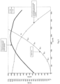
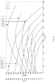
Referring now to FIG. 3 , a diagram showing various characteristic curves of an exemplary fan, a plurality of recorded duty points Bi,v (i=1, . . . , m−i) during forward rotation, and the operating point Av during the forward rotation. A similar diagram is shown in FIG. 4 for a first exemplary embodiment. In FIG. 5 , another diagram showing various characteristic curves of an exemplary fan, a plurality of recorded duty points Bi,v (i=1, . . . , m−i) during forward rotation, and the unambiguous operating point Av during the forward rotation is provided for a second exemplary embodiment.
Referring now to FIG. 6 , a diagram is provided that illustrates various characteristic curves of an exemplary fan, an operating point Av during forward rotation, and a domain bounded by two polynomials, e.g. a line through the origin and a parabola through the origin.
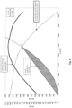
In FIG. 7 , a diagram is provided that shows various characteristic curves of an exemplary fan, a plurality of recorded duty points Bj,i,v (j=1.2; i=1, . . . , m−1) during forward rotation, an operating point A1,v and an operating point A2,v during forward rotation, a first domain D1, which is bounded by two polynomials, and a second domain D2, which is bounded by two polynomials according to the first exemplary embodiment. A similar diagram is provided in FIG. 8 , that illustrates various characteristic curves of an exemplary fan, a plurality of recorded duty points Bj,i,v (j=1, 2; i=1, . . . , m−1) during forward rotation, a possible operating point A1,v and an operating point A2,v during forward rotation, a first domain D1, which is bounded by two polynomials, and a second domain D2, which is bounded by two polynomials according to the second exemplary embodiment.
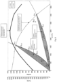
Referring now to FIG. 9 , a diagram is provided that shows various characteristic curves of an exemplary fan, a plurality of recorded duty points Bj,i,v (j=1, 2; i=1, . . . , m−1) during forward rotation, a plurality of recorded duty points Bi,R (i=1, . . . , k−1) during reverse rotation, an operating point A1,v and an operating point A2,v during forward rotation, an operating point AR during reverse rotation, and in each case a system compensation curve through the duty points B1,i,v, B2,i,v, Bi,R according to the first exemplary embodiment.
In FIG. 10 , a diagram is provided that illustrates various characteristic curves of an exemplary fan, a plurality of recorded duty points Bj,i,v (j=1, 2; i=1, . . . , m−1) during forward rotation, a plurality of recorded duty points Bi,R (i=1, . . . , k−1) during reverse rotation, an operating point A1,v and an operating point A2,v during forward rotation, an operating point AR during reverse rotation, and in each case a system compensation curve through the duty points B1,i,v, B2,i,v, Bi,R according to the second exemplary embodiment.
Referring now to FIG. 11 , a diagram is provided that shows various characteristic curves of an exemplary fan, a plurality of recorded duty points Bj,i,v (j=1, 2; i=1, . . . , m−1) during forward rotation, a plurality of recorded duty points Bj,i,R (j=1, 2; i=1, . . . , k−1) during reverse rotation, an operating point A1,v and an operating point A2,v during forward rotation, an operating point A1,R during reverse rotation, and in each case a system compensation curve through the duty points B1,i,v, B2,i,v, B2,i,R.
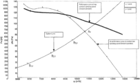
Referring now to FIG. 12 , an exemplary set of characteristic fan curves is provided with technical flow parameters and motor parameters during forward operation, plotted over volumetric flow rate, pressure, and performance.
In FIG. 13 , an exemplary set of characteristic fan curves is provided with technical flow parameters and motor parameters during reverse operation, plotted over volumetric flow rate, pressure, and performance.
While the above description constitutes the preferred embodiments of the present invention, it will be appreciated that the invention is susceptible to modification, variation and change without departing from the proper scope and fair meaning of the accompanying claims.

Claims (15)

The invention claimed is:
1. A method for determining the operating point of an electric motor-driven fan in a system, wherein the method comprises:
providing at least one startup of the fan, the at least one startup being a forward-rotation startup or a reverse-rotation startup;
measuring motor parameters Mi and/or Mi,R for a plurality of speeds during the at least one startup; determining technical flow parameters Pi,v and/or Pi,R for the plurality of speeds; and determining a clear correlation between the technical flow parameters Pi,v and the motor parameters during forward rotation is not possible or a clear correlation between the technical flow parameters Pi,R and the motor parameters Mi,R during reverse rotation is not possible, such that the operating point cannot be determined; and in response to determining the operating point cannot be determined, a first domain D1 and a second domain D2 are defined in a curve diagram for the fan, between two polynomial functions, which intersect in each case at one of two possible operating points A1,v and A2,v, respectively, during forward operation of the fan; wherein Pi,v is then referred to as Pj,i,v with the subscript j being a 1 or 2 to reflect the first domain D1 or the second domain D2, and the subscript v refers to the forward-rotation startup and the subscript R refers to the reverse-rotation startup; wherein recorded duty points during forward rotation are compared with first domain D1 and second domain D2, the subscript j is a 1 or 2 to reflect the first domain D1 or the second domain D2, and
i). a first determination is made that at least one of the recorded duty points or B1,i,v (i=1, . . . , m−1) lies outside of the defined first domain D1 and further, or
a second determination is made that all of the recorded duty points (i=1, . . . , m−1) lie within the second domain D2,
in response to the first or second determination, the operating point is determined as A2,v,
or
ii). a third determination is made that at least one of the recorded duty points B2,i,v (i=1, . . . , m−1) lies outside of the defined second domain D2, or
a fourth determination is made that all of the recorded duty points B1,i,v (i=1, . . . , m−1) lie within the first domain D1,
in response to the third or fourth determination, the operating point is determined as A1,v, wherein the subscript i refers to the plurality of speeds.
2. The method according to claim 1, wherein one startup is performed, and the one startup is a forward-rotation startup.
3. The method according to claim 1, wherein one startup is performed, and the one startup is a reverse-rotation startup.
4. The method according to claim 1, wherein two startups are performed, and the two startups correspond to a forward-rotation startup and a reverse-rotation startup, in a desired sequence.
5. The method according to claim 1, wherein a clear correlation between the technical flow parameters Pi,R and the motor parameters Mi,R exists during reverse rotation and a forward-rotation startup has been carried out, then a system compensation curve fforward,1(P1,i,v) through duty points B1,i,v and a system compensation curve fforward,2(P2,i,v) through duty points B2,i,v from the forward-rotation startup and a system compensation curve freverse(Pi,R) through duty points Bi,R from the reverse-rotation startup are used to determine the operating point.
6. The method according to claim 2, wherein no clear correlation between the technical flow parameters Pi,v and the motor parameters Mi,v during forward rotation exists, a first domain D1 and a second domain D2 are defined in a curve diagram for the fan, in each case between two polynomial functions, which intersect in each case at one of two possible operating points A1,v and A2,v, respectively, during forward operation of the fan;
wherein Pi,v may be written as Pj,i,v with the subscript j being a 1 or 2 to reflect the first domain D1 or the second domain D2.
7. The method according to claim 3, wherein no clear correlation between the technical flow parameters Pi,v and the motor parameters Mi,v during forward rotation exists, a first domain D1 and a second domain D2 are defined in a curve diagram for the fan, in each case between two polynomial functions, which intersect in each case at one of two possible operating points A1,v and A2,v, respectively, during forward operation of the fan;
wherein Pi,v may be written as Pj,i,v with the subscript j being a 1 or 2 to reflect the first domain D1 or the second domain D2.
8. The method according to claim 4, wherein no clear correlation between the technical flow parameters Pi,v and the motor parameters Mi,v during forward rotation exists, a first domain D1 and a second domain D2 are defined in a curve diagram for the fan, in each case between two polynomial functions, which intersect in each case at one of two possible operating points A1,v and A2,v, respectively, during forward operation of the fan;
wherein Pi,v may be written as Pj,i,v with the subscript j being a 1 or 2 to reflect the first domain D1 or the second domain D2.
9. The method according to claim 6, wherein recorded duty points Bj,i,v during forward rotation are compared with first domain D1 and second domain D2, wherein the subscript j is a 1 or 2 to reflect the first domain D1 or the second domain D2, and
when at least one of the recorded duty points B1,i,v (i=1, . . . , m−1) lies outside of the defined first domain D1 and further, when all of the recorded duty points B2,i,v (i=1, . . . , m−1) lie within the second domain D2, the operating point is determined as A2,v, and
when at least one of the recorded duty points B2,i,v (i=1, . . . , m−1) lies outside of the defined second domain D2, and further, when all of the recorded duty points B1,i,v (i=1, . . . , m−1) lie within the first domain D1, the operating point is determined as A1,v.
10. The method according to claim 9, wherein a clear correlation between the technical flow parameters Pi,R and the motor parameters Mi,R during reverse rotation exists and a forward-rotation startup has been carried out, then a system compensation curve fforward,1(P1,i,v) through duty points B1,i,v and a system compensation curve fforward,2(P2,i,v) through duty points B2,i,v from the forward-rotation startup and a system compensation curve freverse(Pi,R) through duty points Bi,R from the reverse-rotation startup are used to determine the operating point.
11. The method according to claim 7, wherein recorded duty points Bj,i,v during forward rotation are compared with first domain D1 and second domain D2, wherein the subscript j is a 1 or 2 to reflect the first domain D1 or the second domain D2, and
when at least one of the recorded duty points B1,i,v (i=1, . . . , m−1) lies outside of the defined first domain D1 and further, when all of the recorded duty points B2,i,v (i=1, . . . , m−1) lie within the second domain D2, the operating point is determined as A2,v, and
when at least one of the recorded duty points B2,i,v (i=1, . . . , m−1) lies outside of the defined second domain D2, and further, when all of the recorded duty points B1,i,v (i=1, . . . , m−1) lie within the first domain D1, the operating point is determined as A1,v.
12. The method according to claim 11, wherein a clear correlation between the technical flow parameters Pi,R and the motor parameters Mi,R during reverse rotation exists and a forward-rotation startup has been carried out, then a system compensation curve fforward,1(P1,i,v) through duty points B1,i,v and a system compensation curve fforward,2(P2,i,v) through duty points B2,i,v from the forward-rotation startup and a system compensation curve freverse(Pi,R) through duty points Bi,R from the reverse-rotation startup are used to determine the operating point.
13. The method according to claim 8, wherein recorded duty points Bj,i,v during forward rotation are compared with first domain D1 and second domain D2, wherein the subscript j is a 1 or 2 to reflect the first domain D1 or the second domain D2, and
when at least one of the recorded duty points B1,i,v (i=1, . . . , m−1) lies outside of the defined first domain D1 and further, when all of the recorded duty points B2,i,v (i=1, . . . , m−1) lie within the second domain D2, the operating point is determined as A2,v, and
when at least one of the recorded duty points B2,i,v (i=1, . . . , m−1) lies outside of the defined second domain D2, and further, when all of the recorded duty points B1,i,v (i=1, . . . , m−1) lie within the first domain D1, the operating point is determined as A1,v.
14. The method according to claim 13, wherein a clear correlation between the technical flow parameters Pi,R and the motor parameters Mi,R during reverse rotation exists and a forward-rotation startup has been carried out, then a system compensation curve fforward,1(P1,i,v) through duty points B1,i,v and a system compensation curve fforward,2(P2,i,v) through duty points B2,i,v from the forward-rotation startup and a system compensation curve freverse(Pi,R) through duty points Bi,R from the reverse-rotation startup are used to determine the operating point.
15. A method for determining the operating point of an electric motor-driven fan in a system, wherein the method comprises:
providing first startup of the fan, the first startup being a forward-rotation startup or a reverse-rotation startup;
measuring motor parameters Mi,v or Mi,R for a plurality of speeds during the startup;
determining technical flow parameters Pi,v or Pi,R for the plurality of speeds; and
determining that a clear correlation between the technical flow parameters Pi and the motor parameters Mi does not exist such that a determination of the operating point is not possible, and in response
providing a second startup of the fan, the second startup being opposite in direction of the first startup; and
determining an operating point of the fan based on the motor parameters measured from the first start up and the second startup;
wherein the subscript i refers to the plurality of speeds, the subscript v refers to the forward-rotation startup and the subscript R refers to the reverse-rotation startup.
US16/970,684 2018-02-27 2019-02-26 Method for determining the operating point Active 2040-02-09 US11846292B2 (en)

Applications Claiming Priority (3)

Application Number Priority Date Filing Date Title
DE102018104394.5A DE102018104394A1 (en) 2018-02-27 2018-02-27 Operating point determination
DE102018104394.5 2018-02-27
PCT/EP2019/054769 WO2019166448A1 (en) 2018-02-27 2019-02-26 Method for determining the operating point

Publications (2)

Publication Number Publication Date
US20200378392A1 US20200378392A1 (en) 2020-12-03
US11846292B2 true US11846292B2 (en) 2023-12-19

Family

ID=65685312

Family Applications (1)

Application Number Title Priority Date Filing Date
US16/970,684 Active 2040-02-09 US11846292B2 (en) 2018-02-27 2019-02-26 Method for determining the operating point

Country Status (5)

Country Link
US (1) US11846292B2 (en)
EP (1) EP3707387B1 (en)
CN (1) CN111656018B (en)
DE (1) DE102018104394A1 (en)
WO (1) WO2019166448A1 (en)

Families Citing this family (1)

* Cited by examiner, † Cited by third party
Publication number Priority date Publication date Assignee Title
DE102020118251A1 (en) * 2020-07-10 2022-01-13 Ebm-Papst Mulfingen Gmbh & Co. Kg Method and fan system for determining the condition of a filter in a fan unit

Citations (16)

* Cited by examiner, † Cited by third party
Publication number Priority date Publication date Assignee Title
DE2502444A1 (en) 1974-12-18 1976-06-24 Bbc Brown Boveri & Cie PROCEDURE AND DEVICE FOR STARTING UP A FAN
DE19506790A1 (en) 1994-02-28 1995-09-21 Kuehnle Kopp Kausch Ag Operating efficiency optimisation system for radial compressor
US5743715A (en) 1995-10-20 1998-04-28 Compressor Controls Corporation Method and apparatus for load balancing among multiple compressors
DE19726547A1 (en) 1997-06-23 1999-01-28 Babcock Bsh Gmbh Method for determining the operating point of a fan and fan
DE10154783A1 (en) 2001-11-08 2003-05-22 Buderus Heiztechnik Gmbh Control system for air volume flow of ventilator and air supply fan and operation of gas burner for heater incorporates Hall-sensor to sense passage of fan blades and measure speed of fan
US20090180897A1 (en) 2008-01-15 2009-07-16 Asia Vital Components Co., Ltd. Fan enabling increased wind pressure and air volume
US20110200454A1 (en) 2010-02-10 2011-08-18 Abb Oy Method in connection with a pump driven with a frequency converter and frequency converter
DE102011106962A1 (en) 2010-07-08 2012-02-23 Johnson Electric S.A. fan
CN102439318A (en) 2009-05-20 2012-05-02 Ksb股份公司 Method and device for determining an operating point of a work machine
US20120251340A1 (en) * 2011-03-29 2012-10-04 Abb Oy Method for improving sensorless flow rate estimation accuracy of pump driven with frequency converter
EP2508811A1 (en) 2011-04-08 2012-10-10 Zehnder Verkaufs- und Verwaltungs AG Device for calculating the volume flow transported by a ventilator
US20130015251A1 (en) * 2011-07-12 2013-01-17 Ctb, Inc. Bin aeration system
WO2013052517A2 (en) 2011-10-07 2013-04-11 Honeywell International Inc. System and method of calibration in a powered air purifying respirator
CN103452883A (en) 2012-05-31 2013-12-18 中山大洋电机股份有限公司 A variable speed fan system and its control method
WO2015058945A1 (en) 2013-10-23 2015-04-30 Güntner Gmbh & Co. Kg Method for controlling a motor for a fan in a heat exchanger, control apparatus for a fan and heat exchanger
CN104791281A (en) 2015-04-17 2015-07-22 国网智能电网研究院 Draught fan control device and control method in power electronic power cabinet

Family Cites Families (9)

* Cited by examiner, † Cited by third party
Publication number Priority date Publication date Assignee Title
DE59909585D1 (en) 1999-03-23 2004-07-01 Ebm Papst Mulfingen Gmbh & Co Blower with a predetermined characteristic
DE10035829C2 (en) 1999-08-14 2002-07-18 Ziehl Abegg Gmbh & Co Kg Method for operating a ventilation device and ventilation device
US6591697B2 (en) 2001-04-11 2003-07-15 Oakley Henyan Method for determining pump flow rates using motor torque measurements
SE0103371D0 (en) 2001-10-09 2001-10-09 Abb Ab Flow measurements
DE102008029910C5 (en) 2008-06-24 2020-03-05 BSH Hausgeräte GmbH Method for recognizing the load status of a pump
DE102012006444A1 (en) 2012-03-30 2013-10-02 Wilo Se Method for operating a pump set
ES2643743T3 (en) 2013-04-30 2017-11-24 Gidelmar, S.A. Method and system of automatic adjustment of the operation of a fan, and computer program that implements the method
DE102014008716B4 (en) 2014-06-18 2022-01-13 Wilo Se Procedure for detecting a dry run
CN108331777B (en) 2017-01-20 2021-04-30 德昌电机(深圳)有限公司 Motor fan device, air fluidity adjusting equipment and air volume control method

Patent Citations (16)

* Cited by examiner, † Cited by third party
Publication number Priority date Publication date Assignee Title
DE2502444A1 (en) 1974-12-18 1976-06-24 Bbc Brown Boveri & Cie PROCEDURE AND DEVICE FOR STARTING UP A FAN
DE19506790A1 (en) 1994-02-28 1995-09-21 Kuehnle Kopp Kausch Ag Operating efficiency optimisation system for radial compressor
US5743715A (en) 1995-10-20 1998-04-28 Compressor Controls Corporation Method and apparatus for load balancing among multiple compressors
DE19726547A1 (en) 1997-06-23 1999-01-28 Babcock Bsh Gmbh Method for determining the operating point of a fan and fan
DE10154783A1 (en) 2001-11-08 2003-05-22 Buderus Heiztechnik Gmbh Control system for air volume flow of ventilator and air supply fan and operation of gas burner for heater incorporates Hall-sensor to sense passage of fan blades and measure speed of fan
US20090180897A1 (en) 2008-01-15 2009-07-16 Asia Vital Components Co., Ltd. Fan enabling increased wind pressure and air volume
CN102439318A (en) 2009-05-20 2012-05-02 Ksb股份公司 Method and device for determining an operating point of a work machine
US20110200454A1 (en) 2010-02-10 2011-08-18 Abb Oy Method in connection with a pump driven with a frequency converter and frequency converter
DE102011106962A1 (en) 2010-07-08 2012-02-23 Johnson Electric S.A. fan
US20120251340A1 (en) * 2011-03-29 2012-10-04 Abb Oy Method for improving sensorless flow rate estimation accuracy of pump driven with frequency converter
EP2508811A1 (en) 2011-04-08 2012-10-10 Zehnder Verkaufs- und Verwaltungs AG Device for calculating the volume flow transported by a ventilator
US20130015251A1 (en) * 2011-07-12 2013-01-17 Ctb, Inc. Bin aeration system
WO2013052517A2 (en) 2011-10-07 2013-04-11 Honeywell International Inc. System and method of calibration in a powered air purifying respirator
CN103452883A (en) 2012-05-31 2013-12-18 中山大洋电机股份有限公司 A variable speed fan system and its control method
WO2015058945A1 (en) 2013-10-23 2015-04-30 Güntner Gmbh & Co. Kg Method for controlling a motor for a fan in a heat exchanger, control apparatus for a fan and heat exchanger
CN104791281A (en) 2015-04-17 2015-07-22 国网智能电网研究院 Draught fan control device and control method in power electronic power cabinet

Non-Patent Citations (1)

* Cited by examiner, † Cited by third party
Title
European Patent Office, Rijswijk, Netherlands, International Search Report of International Application No. PCT/EP2019/054769, dated Jun. 12, 2019, 2 pages.

Also Published As

Publication number Publication date
US20200378392A1 (en) 2020-12-03
DE102018104394A1 (en) 2019-08-29
WO2019166448A1 (en) 2019-09-06
EP3707387B1 (en) 2024-10-09
CN111656018B (en) 2022-03-29
EP3707387A1 (en) 2020-09-16
CN111656018A (en) 2020-09-11

Similar Documents

Publication Publication Date Title
US8152496B2 (en) Continuing compressor operation through redundant algorithms
US6591697B2 (en) Method for determining pump flow rates using motor torque measurements
CN101581254B (en) Method and device for estimating intake air flow rate in internal combustion engine
KR102045801B1 (en) Specimen Character Estimation Method and Specimen Character Estimation Apparatus
CN110056443B (en) A kind of detection method and system of Venturi tube upstream pressure
US11846292B2 (en) Method for determining the operating point
CN112955723B (en) Electric drive unit and method for temperature calculation in an electric drive unit
CN101646858A (en) Method for determining the size of a leak
CN104819500B (en) Extractor hood as well as gas flow detection method, device and air speed control method
JP2003247449A (en) Method of calculating gas pressure on the basis of pressure in intake line of internal combustion engine
JP4621953B2 (en) Method of operating a vehicle and vehicle
US20230272799A1 (en) Method and fan system for determination of a current operating point of a fan unit
JPS5990016A (en) Method of measuring flow rate of medium
JPH0421809B2 (en)
KR950033015A (en) Method and apparatus for detecting cylinder inflow air of internal combustion engine, and method and apparatus for fuel control of internal combustion engine using the method and apparatus
EP3482081B1 (en) Compressor anti-surge protection under wet gas conditions
JP2000065671A (en) Method for testing the functionality of containers, especially tank venting equipment
CN110382872A (en) Circulating pump for running the method for circulating pump and for implementing this method
JP2006343136A (en) Water vapor partial pressure detection device, engine intake flow rate detection device, and collector internal pressure detection device
CN114696663B (en) Motor temperature determination method, device and vehicle
JP2006094669A (en) Electric vehicle drive control device
CN111742146A (en) parameter stability
JP2000161120A (en) Method for measuring throttle valve angle
Ghanes et al. Backstepping Observer validation for sensorless induction motor on low frequencies Benchmark
Tamminen et al. Sensorless flow rate estimation in frequency-converter-driven fans

Legal Events

Date Code Title Description
AS Assignment

Owner name: EBM-PAPST MULFINGEN GMBH & CO. KG, GERMANY

Free format text: ASSIGNMENT OF ASSIGNORS INTEREST;ASSIGNORS:GOETZINGER, MARVIN;REICHERT, ERIK;WECKERT, MARCO;AND OTHERS;SIGNING DATES FROM 20200618 TO 20200622;REEL/FRAME:053522/0725

FEPP Fee payment procedure

Free format text: ENTITY STATUS SET TO UNDISCOUNTED (ORIGINAL EVENT CODE: BIG.); ENTITY STATUS OF PATENT OWNER: LARGE ENTITY

STPP Information on status: patent application and granting procedure in general

Free format text: DOCKETED NEW CASE - READY FOR EXAMINATION

STPP Information on status: patent application and granting procedure in general

Free format text: NON FINAL ACTION MAILED

STPP Information on status: patent application and granting procedure in general

Free format text: RESPONSE TO NON-FINAL OFFICE ACTION ENTERED AND FORWARDED TO EXAMINER

STPP Information on status: patent application and granting procedure in general

Free format text: AWAITING TC RESP., ISSUE FEE NOT PAID

STPP Information on status: patent application and granting procedure in general

Free format text: NOTICE OF ALLOWANCE MAILED -- APPLICATION RECEIVED IN OFFICE OF PUBLICATIONS

STPP Information on status: patent application and granting procedure in general

Free format text: PUBLICATIONS -- ISSUE FEE PAYMENT RECEIVED

STPP Information on status: patent application and granting procedure in general

Free format text: PUBLICATIONS -- ISSUE FEE PAYMENT VERIFIED

STCF Information on status: patent grant

Free format text: PATENTED CASE