EP3707387B1 - Arbeitspunktbestimmung - Google Patents
Arbeitspunktbestimmung Download PDFInfo
- Publication number
- EP3707387B1 EP3707387B1 EP19708984.0A EP19708984A EP3707387B1 EP 3707387 B1 EP3707387 B1 EP 3707387B1 EP 19708984 A EP19708984 A EP 19708984A EP 3707387 B1 EP3707387 B1 EP 3707387B1
- Authority
- EP
- European Patent Office
- Prior art keywords
- fan
- operating point
- startup
- rotation
- determined
- Prior art date
- Legal status (The legal status is an assumption and is not a legal conclusion. Google has not performed a legal analysis and makes no representation as to the accuracy of the status listed.)
- Active
Links
Images


Classifications
-
- F—MECHANICAL ENGINEERING; LIGHTING; HEATING; WEAPONS; BLASTING
- F04—POSITIVE - DISPLACEMENT MACHINES FOR LIQUIDS; PUMPS FOR LIQUIDS OR ELASTIC FLUIDS
- F04D—NON-POSITIVE-DISPLACEMENT PUMPS
- F04D25/00—Pumping installations or systems
- F04D25/02—Units comprising pumps and their driving means
- F04D25/06—Units comprising pumps and their driving means the pump being electrically driven
-
- F—MECHANICAL ENGINEERING; LIGHTING; HEATING; WEAPONS; BLASTING
- F04—POSITIVE - DISPLACEMENT MACHINES FOR LIQUIDS; PUMPS FOR LIQUIDS OR ELASTIC FLUIDS
- F04D—NON-POSITIVE-DISPLACEMENT PUMPS
- F04D25/00—Pumping installations or systems
- F04D25/02—Units comprising pumps and their driving means
- F04D25/08—Units comprising pumps and their driving means the working fluid being air, e.g. for ventilation
-
- F—MECHANICAL ENGINEERING; LIGHTING; HEATING; WEAPONS; BLASTING
- F04—POSITIVE - DISPLACEMENT MACHINES FOR LIQUIDS; PUMPS FOR LIQUIDS OR ELASTIC FLUIDS
- F04D—NON-POSITIVE-DISPLACEMENT PUMPS
- F04D27/00—Control, e.g. regulation, of pumps, pumping installations or pumping systems specially adapted for elastic fluids
- F04D27/004—Control, e.g. regulation, of pumps, pumping installations or pumping systems specially adapted for elastic fluids by varying driving speed
-
- Y—GENERAL TAGGING OF NEW TECHNOLOGICAL DEVELOPMENTS; GENERAL TAGGING OF CROSS-SECTIONAL TECHNOLOGIES SPANNING OVER SEVERAL SECTIONS OF THE IPC; TECHNICAL SUBJECTS COVERED BY FORMER USPC CROSS-REFERENCE ART COLLECTIONS [XRACs] AND DIGESTS
- Y02—TECHNOLOGIES OR APPLICATIONS FOR MITIGATION OR ADAPTATION AGAINST CLIMATE CHANGE
- Y02B—CLIMATE CHANGE MITIGATION TECHNOLOGIES RELATED TO BUILDINGS, e.g. HOUSING, HOUSE APPLIANCES OR RELATED END-USER APPLICATIONS
- Y02B30/00—Energy efficient heating, ventilation or air conditioning [HVAC]
- Y02B30/70—Efficient control or regulation technologies, e.g. for control of refrigerant flow, motor or heating
Definitions
- the invention relates to a method for determining the operating point of a fan.
- the invention particularly relates to a method for determining the operating point of a fan in which no clear assignment between the speed, the power and the volume flow of the fan is possible.
- the so-called fan characteristic curve represents the mutual dependence of volume flow and pressure increase.
- the course of the fan characteristic curve depends on the design of the fan.
- the fan characteristics are typically measured and recorded on a suitable fan test bench. It should be noted, however, that the characteristic curves were typically measured under ideal conditions on individual free-standing representative fans of a fan series with unimpeded flow. The actual characteristic curves under installation conditions may deviate from this.
- the system characteristic curve is the flow resistance of a system against which the fan must work.
- the operating point of a fan used in an application is the intersection of the fan and system characteristic curve.
- the operating point can be determined directly after recording the motor parameters, since the operating point is only located at one possible intersection point of the fan characteristic curve and system characteristic curve (operating point). If the assignment is not clear, the fan could theoretically be at several operating points after recording the motor parameters, since there is no information about the volume flow. It is not clear which of the operating points this is, since without a sensor only the motor parameters can be measured and checked.
- a widely used method for determining the volume flow is, for example, the differential pressure measurement method. Using pressure sampling nozzles, pressure hoses and a pressure sensor, the differential pressure between the intake nozzle of the fan and a reference point in the system can be determined. The measured pressure difference is proportional to the product from air density and the square of the volume flow. From this, the volume flow of the fan in the system when installed can be determined. Once the volume flow in an application has been determined, the operating point can be determined from a previously measured fan characteristic map of the fan.
- a device for determining the volume flow transported by a fan is known, which is provided in the area of an inlet nozzle of the fan and a pressure difference sensor for connecting a measuring opening with a reference pipe.
- the invention is therefore based on the object of proposing a universally applicable method for determining the operating point of a fan, in particular a method for determining the operating point of a fan in which no clear assignment between the speed, the power and the volume flow of the fan is possible.
- a basic idea of the invention is to provide a universal solution for different Fan designs are to be provided, the operating point A being determined on the basis of motor parameters M by means of start-ups.
- a method is therefore proposed for determining the operating point of a fan operated by an electric motor in a system, the method comprising at least one start-up of the fan.
- the operating point of the fan can be determined on the basis of motor parameters M (e.g. speed, power, current, torque) of the fan during at least one of these start-ups.
- the motor parameters Mi are measured for a large number of speeds.
- the fluidic parameters Pi e.g. volume flow, pressure
- are determined preferably from a measured fan characteristic map consisting of fluidic parameters and motor parameters or via the relevant fan laws.
- Either a forward run or a reverse run can be carried out to determine the operating point. In some cases, two start-ups are necessary to determine the operating point. The order of the start-ups is not important.
- one or more operating points are approached by increasing or decreasing the speed of the fan along a system characteristic curve.
- the direction of rotation can be taken from the fan specification and corresponds to the operating direction of rotation.
- the operating point A v can be determined.
- the operating point A v can be determined.
- a first definition range D 1 and a second definition range D2 are defined in the characteristic diagram of the fan between two polynomial functions (e.g. by an origin parabola and an origin straight line), which each intersect at one of the two possible operating points A 1,V or A 2,V in forward operation of the fan.
- the balancing system characteristic curve f forward,1 (P 1,i,V ) is determined by the operating points B 1,i,V and the balancing system characteristic curve f forward,2 (P 2,i,V ) by the operating points B 2,i,V ; from the forward run and the balancing system characteristic curve f backward (P i,R ) through the operating points B i,R from the reverse run is used to determine the operating point.
- the operating point A 1,V is determined as the operating point.
- the operating point A 2,V is determined as the operating point.
- a first balancing system characteristic curve f forward,1 (P 1,i,V ) through the operating points B 1,i,V and a second balancing system characteristic curve f forward,2 (P 2,i,V ) through the operating points B 2,i,V from the forward operation and a first balancing system characteristic curve f backward,1 (P 1,i,R ) through the operating points B 1,i,R and a second balancing system characteristic curve f backward,2 (P 2,i,R ) through the operating points B 2,i,R from the reverse operation are used to determine the operating point.
- the operating point A 1,V is determined as the operating point.
- the operating point A 2,V is determined as the operating point.
Landscapes
- Engineering & Computer Science (AREA)
- Mechanical Engineering (AREA)
- General Engineering & Computer Science (AREA)
- Control Of Positive-Displacement Air Blowers (AREA)
Description
- Die Erfindung betrifft ein Verfahren zur Arbeitspunktbestimmung eines Ventilators. Die Erfindung betrifft insbesondere ein Verfahren zur Arbeitspunktbestimmung eines Ventilators bei dem keine eindeutige Zuordnung zwischen der Drehzahl, der Leistung und dem Volumenstrom des Ventilators möglich ist.
- Die sogenannte Ventilatorkennlinie stellt die gegenseitige Abhängigkeit von Volumenstrom und Druckerhöhung dar. Der Verlauf der Ventilatorkennlinie hängt von der Bauart des Ventilators ab. Die Ventilatorkennlinien werden typischerweise an einem dazu geeigneten Ventilatorprüfstand gemessen und erfasst. Zu beachten ist allerdings, dass die Kennlinien typischerweise unter Idealbedingungen an einzelnen freistehenden repräsentativen Lüftern einer Ventilatorbaureihe mit ungehinderter Strömung gemessen wurden. Die realen Kennlinien unter Einbaubedingungen können davon abweichen.
- Die Anlagenkennlinie ist der Strömungswiderstand einer Anlage, gegen den der Ventilator arbeiten muss. Der Arbeitspunkt eines Ventilators, der in einer Applikation eingesetzt ist, ergibt sich als Schnittpunkt von Ventilator- und Anlagenkennlinie.
- Man unterscheidet zwischen einer eindeutigen Zuordnung und keiner eindeutigen Zuordnung zwischen der Drehzahl, der Leistung und dem Volumenstrom oder Druck des Ventilators. Bei einer eindeutigen Zuordnung kann der Arbeitspunkt direkt nach der Aufnahme der Motorparameter bestimmt werden, da sich der Arbeitspunkt nur in einem möglichen Schnittpunkt der Ventilatorkennlinie und Anlagenkennlinie (Arbeitspunkt) befindet. Wenn die Zuordnung nicht eindeutig ist, könnte sich der Ventilator nach der Aufnahme der Motorparameter theoretisch in mehreren Arbeitspunkten befinden, da keine Information über den Volumenstrom vorliegt. Welcher der Arbeitspunkte das ist, ist nicht ersichtlich, da ohne einen Sensor nur die Motorparameter gemessen und überprüft werden können.
- In Anwendungen ist es notwendig den Volumenstrom und somit den Arbeitspunkt eines Ventilators zu bestimmen. Es gibt hierzu sensorbasierte Verfahren, die den Volumenstrom des Ventilators näherungsweise bestimmen können. Ein weit verbreitetes Verfahren zur Bestimmung des Volumenstroms ist z. B. das Differenzdruckmessverfahren. Mithilfe von Druckentnahmestutzen, Druckschläuchen und einem Drucksensor kann der Differenzdruck zwischen der Ansaugdüse des Ventilators und einem Referenzpunkt in der Anlage bestimmt werden. Die gemessene Druckdifferenz ist proportional zum Produkt aus Luftdichte und dem Quadrat des Volumenstroms. Hieraus kann wiederum der Volumenstrom des Ventilators in der Anlage im eingebauten Zustand ermittelt werden. Wenn der Volumenstrom in einer Anwendung bestimmt ist, kann der Arbeitspunkt aus einem zuvor gemessenen Ventilatorkennfeld des Ventilators bestimmt werden.
- Diese Lösung ist jedoch aufgrund des hohen Montageaufwandes, der zusätzlichen Materialkosten und der teilweise unzureichenden Genauigkeit bei der Volumenstrombestimmung unzuverlässig und kostenintensiv.
- Aus der
EP 2 508 811 B1 ist eine Vorrichtung zur Ermittlung des von einem Ventilator transportierten Volumenstroms bekannt, die im Bereich einer Einlaufdüse des Ventilators vorgesehen ist sowie einem Druckdifferenzsensor zur Verbindung einer Messöffnung mit einem Referenzrohr. - Um jedoch einen optimalen Betrieb zu gewährleisten, ist es notwendig, dass in jedem Betriebspunkt des Ventilators dem Volumenstrom eine Druckerhöhung eindeutig zugeordnet werden kann, d. h. der Ventilator muss gemäß einer stetigen Kennlinie arbeiten können.
- Weiterer druckschriftlicher Stand der Technik auf dem vorliegenden technischen Gebiet, welcher den Oberbegriff des Anspruchs 1 widerspiegelt, ist in dem Dokument
DE 10 2011 106 962 A1 offenbart. - Der Erfindung liegt deshalb die Aufgabe zugrunde, ein universell anwendbares Verfahren zur Arbeitspunktbestimmung eines Ventilators vorzuschlagen, insbesondere ein Verfahren zur Arbeitspunktbestimmung eines Ventilators bei dem keine eindeutige Zuordnung zwischen der Drehzahl, der Leistung und dem Volumenstrom des Ventilators möglich ist.
- Diese Aufgabe wird durch die Merkmalskombination gemäß Anspruch 1 gelöst.
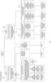
- Ein Grundgedanke der Erfindung liegt darin, eine universelle Lösung für unterschiedliche Ventilatorbauarten vorzusehen, wobei mittels Hochläufen der Arbeitspunkt A anhand von Motorparametern M bestimmt wird. Erfindungsgemäß wird daher ein Verfahren zur Arbeitspunktbestimmung eines von einem Elektromotor betriebenen Ventilators in einer Anlage vorgeschlagen, wobei das Verfahren mindestens einen Hochlauf des Ventilators umfasst. Anhand von Motorparametern M (z.B. Drehzahl, Leistung, Strom, Drehmoment) des Ventilators kann bei mindestens einem dieser Hochläufe der Arbeitspunkt des Ventilators bestimmt werden. Während des Hochlaufs erfolgt die Messung der Motorparameter Mi für eine Vielzahl von Drehzahlen. Daraus werden die strömungstechnischen Parameter Pi (z.B. Volumenstrom, Druck), vorzugsweise aus einem gemessenen Ventilatorkennfeld, bestehend aus strömungstechnischen Parametern und Motorparametern oder über die einschlägigen Ventilatorgesetze, bestimmt.
- Als Hochlauf kann entweder ein Vorwärtslauf oder ein Rückwärtslauf durchgeführt wenn, um den Arbeitspunkt zu bestimmen. In manchen Fällen sind auch zwei Hochläufe notwendig, um den Arbeitspunkt zu bestimmen. Die Reihenfolge der Hochläufe spielt dabei keine Rolle.
- Bei einem Vorwärtslauf werden einer oder mehrere Arbeitspunkte durch Erhöhung oder Verringerung der Drehzahl des Ventilators entlang einer Anlagenkennlinie angefahren. Die Drehrichtung kann der Spezifikation des Ventilators entnommen werden und entspricht der Betriebsdrehrichtung.
- Bei einem Rückwärtslauf werden einer oder mehrere Arbeitspunkte durch Erhöhung oder Verringerung der Drehzahl des Ventilators entlang einer Anlagenkennlinie angefahren. Die Drehrichtung ist entgegengesetzt der Betriebsdrehrichtung des Ventilators.
- Für den Fall, dass eine eindeutige Zuordnung zwischen den strömungstechnischen Parametern Pi,v und den Motorparametern Mi,v im Vorwärtslauf möglich ist, kann der Arbeitspunkt Av bestimmt werden.
- Für den Fall, dass eine eindeutige Zuordnung zwischen den strömungstechnischen Parametern Pi,R und den Motorparametern Mi,R im Rückwärtslauf möglich ist, kann der Arbeitspunkt Av bestimmt werden.
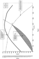
- Für den Fall, dass keine eindeutige Zuordnung zwischen den strömungstechnischen Parametern P j,i,v und den Motorparametern Mi,v im Vorwärtslauf möglich ist, wird ein erster Definitionsbereich D1 und ein zweiter Definitionsbereich D2 im Kennliniendiagramm des Ventilators jeweils zwischen zwei Polynomfunktionen (z.B. durch eine Ursprungsparabel und eine Ursprungsgerade) definiert, die sich jeweils in einem der beiden möglichen Arbeitspunkte A1,V bzw. A2,V im Vorwärtsbetrieb des Ventilators schneiden.
- Es erfolgt ein Abgleich der erfassten Betriebspunkte Bj,i,V im Vorwärtslauf mit den Definitionsbereichen D1 und D2. Für den Fall, dass wenigstens einer der erfassten Betriebspunkte B1,i,V (i=1,...,m-1) außerhalb des definierten ersten Definitionsbereichs D1 und ferner alle erfassten Betriebspunkte B2,i,V (i=1,...,m-1) innerhalb des zweiten Definitionsbereichs D2 liegen, ist der Arbeitspunkt A2,V bestimmt.
- Für den Fall, dass wenigstens einer der erfassten Betriebspunkte B2,i,V (i=1,...,m-1) außerhalb des definierten zweiten Definitionsbereichs D2 und ferner alle erfassten Betriebspunkte B1,i,V (i=1,...,m-1) innerhalb des ersten Definitionsbereichs D1 liegen, ist der Arbeitspunkt A1,V bestimmt.
- Für den Fall, dass eine eindeutige Zuordnung zwischen den strömungstechnischen Parametern Pi,R und den Motorparametem Mi,R im Rückwärtslauf möglich ist und ein Vorwärtslauf durchgeführt wurde, wird die Ausgleichsanlagenkennlinie fvowärts,1(P1,i,V) durch die Betriebspunkte B1,i,V und die Ausgleichsanlagenkennlinie fvowärts,2(P2,i,V) durch die Betriebspunkte B2,i,V; aus dem Vorwärtslauf und die Ausgleichsanlagenkennlinie frückwärts (Pi,R) durch die Betriebspunkte Bi,R aus dem Rückwärtslauf zur Bestimmung des Arbeitspunktes verwendet.
- Wenn die aus dem Rückwärtslauf resultierende Ausgleichsanlagenkennlinie frückwärts (Pi,R) näher an der Ausgleichsanlagenkennlinie fvowärts,1(P1,i,V) liegt als an der Ausgleichsanlagenkennlinie fvowärts,2(P2,i,V) ist der Arbeitspunkt A1,V als Arbeitspunkt bestimmt.
- Wenn die aus dem Rückwärtslauf resultierende Ausgleichsanlagenkennlinie frückwärts (Pi,R) näher an der Ausgleichsanlagenkennlinie fvowärts,2(P2,i,V) liegt als an der Ausgleichsanlagenkennlinie fvowärts,1(P1,i,V) ist der Arbeitspunkt A2,V als Arbeitspunkt bestimmt.
- Für den Fall, dass keine eindeutige Zuordnung zwischen den strömungstechnischen Parametern und den Motorparametem Mi,R im Rückwärtslauf möglich ist und ein Vorwärtslauf bereits durchgeführt wurde, wird eine erste Ausgleichsanlagenkennlinie fvowärts,1(P1,i,V) durch die Betriebspunkte B1,i,V und eine zweite Ausgleichsanlagenkennlinie fvowärts,2(P2,i,V) durch die Betriebspunkte B2,i,V aus dem Vorwärtslauf und eine erste Ausgleichsanlagenkennlinie frückwärts,1 (P1,i,R) durch die Betriebspunkte B1,i,R und eine zweite Ausgleichsanlagenkennlinie frückwärts,2 (P2,i,R) durch die Betriebspunkte B2,i,R aus dem Rückwärtslauf zur Bestimmung des Arbeitspunktes verwendet.
- Wenn die Ausgleichsanlagenkennlinie fvowärts,1(P1,i,V) näher an einer der beiden Ausgleichsanlagenkennlinien frückwärts,1 (P1,i,R) und frückwärts,2 (P2,i,R) liegt als die Ausgleichsanlagenkennlinie fvowärts,2(P2,i,V) an den Ausgleichsanlagenkennlinien frückwärts,1 (P1,i,R) und frückwärts,2 (P2,i,R) ist der Arbeitspunkt A1,V als Arbeitspunkt bestimmt.
- Wenn die Ausgleichsanlagenkennlinie fvowärts,2(P2,i,V) näher an einer der beiden Ausgleichsanlagenkennlinien frückwärts,1 (P1,i,R) und frückwärts,2 (P2,i,R) liegt als die Ausgleichsanlagenkennlinie fvowärts,1(P1,i,V) an den Ausgleichsanlagenkennlinien frückwärts,1 (P1,i,R) und frückwärts,2 (P2,i,R) ist der Arbeitspunkt A2,V als Arbeitspunkt bestimmt.
- Andere vorteilhafte Weiterbildungen der Erfindung sind in den Unteransprüchen gekennzeichnet bzw. werden nachstehend zusammen mit der Beschreibung der bevorzugten Ausführung der Erfindung anhand der Figuren näher dargestellt.
- Es zeigen:
-
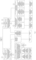
Fig. 1 ein Flussdiagramm zur Darstellung des Prozessablaufs des Verfahrens zur Bestimmung des Arbeitspunktes des Ventilators; -
Fig. 2 ein Flussdiagramm zur Darstellung des Prozessablaufs des Verfahrens zur Bestimmung des Arbeitspunktes des Ventilators anhand eines Ausführungsbeispiels; -
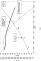
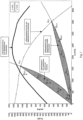
Fig. 3 ein Diagramm mit unterschiedlichen Kennlinien eines beispielhaften Ventilators, einer Vielzahl von aufgenommenen Betriebspunkten Bi,V (i=1,..., m-i) im Vorwärtslauf und dem Arbeitspunkt Av im Vorwärtslauf; -
Fig. 4 ein Diagramm mit unterschiedlichen Kennlinien eines beispielhaften Ventilators, einer Vielzahl von aufgenommenen Betriebspunkten Bi,V (i=1,..., m-i) im Vorwärtslauf und dem Arbeitspunkt Av im Vorwärtslauf (erstes Ausführungsbeispiel); -
Fig. 5 ein Diagramm mit unterschiedlichen Kennlinien eines beispielhaften Ventilators, einer Vielzahl von aufgenommenen Betriebspunkten Bi,V (i=1,..., m-1) im Vorwärtslauf und dem eindeutigen Arbeitspunkt Av im Vorwärtslauf (zweites Ausführungsbeispiel); -
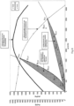
Fig. 6 ein Diagramm mit unterschiedlichen Kennlinien eines beispielhaften Ventilators, einem Arbeitspunkt Av im Vorwärtslauf und einem Definitionsbereich, eingeschlossen zwischen zwei Polynomen, z.B. einer Ursprungsgerade und einer Ursprungsparabel; -
Fig. 7 ein Diagramm mit unterschiedlichen Kennlinien eines beispielhaften Ventilators, einer Vielzahl von aufgenommenen Betriebspunkten Bj,i,v(j=1,2; i=1,...,m-1) im Vorwärtslauf, einem Arbeitspunkt A1,v und einem Arbeitspunkt A2,v im Vorwärtslauf, einem ersten Definitionsbereich D1, der durch zwei Polynome eingeschlossen wird und einem zweiten Definitionsbereich D2, der durch zwei Polynome eingeschlossen wird (erstes Ausführungsbeispiel); -
Fig. 8 ein Diagramm mit unterschiedlichen Kennlinien eines beispielhaften Ventilators, einer Vielzahl von aufgenommenen Betriebspunkten Bj,i,v(j=1,2; i=1,...,m-1) im Vorwärtslauf, einem möglichen Arbeitspunkt A1,v und einem Arbeitspunkt A2,v im Vorwärtslauf, einem ersten Definitionsbereich D1, der durch zwei Polynome eingeschlossen wird und einem zweiten Definitionsbereich D2, der durch zwei Polynome eingeschlossen wird (zweites Ausführungsbeispiel); -
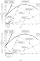
Fig. 9 ein Diagramm mit unterschiedlichen Kennlinien eines beispielhaften Ventilators, einer Vielzahl von aufgenommenen Betriebspunkten Bj,i,v(j=1,2; i=1,...,m-1) im Vorwärtslauf, einer Vielzahl von aufgenommenen Betriebspunkten Bi,R(i=1,...,k-1) im Rückwärtslauf, einem Arbeitspunkt A1,v und einem Arbeitspunkt A2,v im Vorwärtslauf, einem Arbeitspunkt AR im Rückwärtslauf, jeweils eine Ausgleichanlagenkennlinie durch die Betriebspunkte B1,i,v, B2,i,v, Bi,R (erstes Ausführungsbeispiel); -
Fig. 10 ein Diagramm mit unterschiedlichen Kennlinien eines beispielhaften Ventilators, einer Vielzahl von aufgenommenen Betriebspunkten Bj,i,v(j=1,2; i=1,...,m-1) im Vorwärtslauf, einer Vielzahl von aufgenommenen Betriebspunkten Bi,R(i=1,...,k-1) im Rückwärtslauf, einem Arbeitspunkt A1,v und einem Arbeitspunkt A2,v im Vorwärtslauf, einem Arbeitspunkt AR im Rückwärtslauf, jeweils eine Ausgleichanlagenkennlinie durch die Betriebspunkte B1,i,v, B2,i,v, Bi,R (zweites Ausführungsbeispiel); -
Fig. 11 ein Diagramm mit unterschiedlichen Kennlinien eines beispielhaften Ventilators, einer Vielzahl von aufgenommenen Betriebspunkten Bj,i,v(j=1,2; i=1,...,m-1) im Vorwärtslauf, einer Vielzahl von aufgenommenen Betriebspunkten Bj,i,R(j=1,2, i=1,...,k-1) im Rückwärtslauf, einem Arbeitspunkt A1,v und einem Arbeitspunkt A2,v im Vorwärtslauf, einem Arbeitspunkt A1,R im Rückwärtslauf, jeweils eine Ausgleichanlagenkennlinie durch die Betriebspunkte B1,i,v, B2,j,v, B2,i,R; -
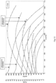
Fig. 12 beispielhaftes Ventilatorkennfeld mit strömungstechnischen Parametern und Motorparametern im Vorwärtsbetrieb, dargestellt mit Volumenstrom, Druck und Leistung und -
Fig. 13 beispielhaftes Ventilatorkennfeld mit strömungstechnischen Parametern und Motorparametern im Rückwärtsbetrieb, dargestellt mit Volumenstrom, Druck und Leistung.
Claims (9)
- Verfahren zur Arbeitspunktbestimmung eines von einem Elektromotor betriebenen Ventilators in einer Anlage, wobei das Verfahren mindestens einen Hochlauf des Ventilators umfasst, wobei anhand von Motorparametern des Ventilators bei wenigstens einem Hochlauf des mindestens einen Hochlaufs der Arbeitspunkt A des Ventilators bestimmt wird, wobei bei dem wenigstens einem Hochlauf des mindestens einen Hochlaufs eine Messung der Motorparametern Mi für eine Vielzahl von Drehzahlen erfolgt und wobei eine Bestimmung von strömungstechnischen Parametern Pi für die Vielzahl unterschiedlicher Drehzahlen erfolgt.
- Verfahren nach Anspruch 1, wobei ein Hochlauf erfolgt und der Hochlauf ein Vorwärtslauf ist.
- Verfahren nach Anspruch 1, wobei ein Hochlauf erfolgt und der Hochlauf ein Rückwärtslauf ist.
- Verfahren nach Anspruch 1, wobei zwei Hochläufe erfolgen und die Hochläufe einem Vorwärtslauf sowie einem Rückwärtslauf in gewünschter Reihenfolge entsprechen.
- Verfahren nach Anspruch 1, wobei für den Fall, dass eine eindeutige Zuordnung zwischen den strömungstechnischen Parametern Pi,v und den Motorparametern Mi,v im Vorwärtslauf möglich ist, der Arbeitspunkt Av bestimmt wird.
- Verfahren nach Anspruch 2, wobei für den Fall, dass eine eindeutige Zuordnung zwischen den strömungstechnischen Parametern und den Motorparametern Mi,R im Rückwärtslauf möglich ist, der Arbeitspunkt Av bestimmt wird.
- Verfahren nach einem der vorhergehenden Ansprüche 1 bis 5, wobei für den Fall, dass keine eindeutige Zuordnung zwischen den strömungstechnischen Parametern P j,i,v und den Motorparametern Mi,v im Vorwärtslauf möglich ist, ein erster Definitionsbereich D1 und ein zweiter Definitionsbereich D2 im Kennliniendiagramm des Ventilators jeweils zwischen zwei Polynomfunktionen definiert wird, die sich jeweils in einem der beiden möglichen Arbeitspunkte A1,V bzw. A2,V im Vorwärtsbetrieb des Ventilators schneiden.
- Verfahren nach Anspruch 7, wobei ein Abgleich der erfassten Betriebspunkte Bj,i,V im Vorwärtslauf mit den Definitionsbereichen D1 und D2 erfolgt undfür den Fall, dass wenigstens einer der erfassten Betriebspunkte B1,i,V (i=1,...,m-1) außerhalb des definierten ersten Definitionsbereichs D1 und ferner alle erfassten Betriebspunkte B2,i,V (i=1,...,m-1) innerhalb des zweiten Definitionsbereichs D2 liegen, der Arbeitspunkt A2,V bestimmt wird undfür den Fall, dass wenigstens einer der erfassten Betriebspunkte B2,i,V (i=1,...,m-1) außerhalb des definierten zweiten Definitionsbereichs D2 und ferner alle erfassten Betriebspunkte B1,i,V (i=1,...,m-1) innerhalb des ersten Definitionsbereichs D1 liegen, der Arbeitspunkt A1,V bestimmt wird.
- Verfahren nach einem der vorhergehenden Ansprüche 2 bis 5, wobei für den Fall, dass eine eindeutige Zuordnung zwischen den strömungstechnischen Parametern und den Motorparametem Mi,R im Rückwärtslauf möglich ist und ein Vorwärtslauf durchgeführt wurde, die Ausgleichsanlagenkennlinie fvowärts,1(P1,i,V) durch die Betriebspunkte B1,i,V und die Ausgleichsanlagenkennlinie fvowärts,2(P2,i,V) durch die Betriebspunkte B2,i,V; aus dem Vorwärtslauf und die Ausgleichsanlagenkennlinie frückwärts (Pi,R) durch die Betriebspunkte Bi,R aus dem Rückwärtslauf zur Bestimmung des Arbeitspunktes verwendet wird.
Applications Claiming Priority (2)
| Application Number | Priority Date | Filing Date | Title |
|---|---|---|---|
| DE102018104394.5A DE102018104394A1 (de) | 2018-02-27 | 2018-02-27 | Arbeitspunktbestimmung |
| PCT/EP2019/054769 WO2019166448A1 (de) | 2018-02-27 | 2019-02-26 | Arbeitspunktbestimmung |
Publications (2)
| Publication Number | Publication Date |
|---|---|
| EP3707387A1 EP3707387A1 (de) | 2020-09-16 |
| EP3707387B1 true EP3707387B1 (de) | 2024-10-09 |
Family
ID=65685312
Family Applications (1)
| Application Number | Title | Priority Date | Filing Date |
|---|---|---|---|
| EP19708984.0A Active EP3707387B1 (de) | 2018-02-27 | 2019-02-26 | Arbeitspunktbestimmung |
Country Status (5)
| Country | Link |
|---|---|
| US (1) | US11846292B2 (de) |
| EP (1) | EP3707387B1 (de) |
| CN (1) | CN111656018B (de) |
| DE (1) | DE102018104394A1 (de) |
| WO (1) | WO2019166448A1 (de) |
Families Citing this family (1)
| Publication number | Priority date | Publication date | Assignee | Title |
|---|---|---|---|---|
| DE102020118251A1 (de) * | 2020-07-10 | 2022-01-13 | Ebm-Papst Mulfingen Gmbh & Co. Kg | Verfahren und Ventilatorsystem zur Ermittlung des Zustands eines Filters in einer Ventilatoreinheit |
Citations (13)
| Publication number | Priority date | Publication date | Assignee | Title |
|---|---|---|---|---|
| DE10035829C2 (de) | 1999-08-14 | 2002-07-18 | Ziehl Abegg Gmbh & Co Kg | Verfahren zum Betreiben einer Lüftungseinrichtung sowie Lüftungseinrichtung |
| US6462494B1 (en) | 1999-03-23 | 2002-10-08 | Ebm Werke Gmbh & Co. | Fan with preset characteristic curve |
| DE10154783A1 (de) | 2001-11-08 | 2003-05-22 | Buderus Heiztechnik Gmbh | Verfahren zur Überwachung des Luftvolumenstromes bei einem Gebläse |
| US6591697B2 (en) | 2001-04-11 | 2003-07-15 | Oakley Henyan | Method for determining pump flow rates using motor torque measurements |
| US6918307B2 (en) | 2001-10-09 | 2005-07-19 | Abb Ab | Device, system and method for on-line monitoring of flow quantities |
| WO2009156326A2 (de) | 2008-06-24 | 2009-12-30 | BSH Bosch und Siemens Hausgeräte GmbH | Verfahren zur lastzustandserkennung einer pumpe |
| DE102011106962A1 (de) | 2010-07-08 | 2012-02-23 | Johnson Electric S.A. | Gebläse |
| US20120251340A1 (en) | 2011-03-29 | 2012-10-04 | Abb Oy | Method for improving sensorless flow rate estimation accuracy of pump driven with frequency converter |
| US20130015251A1 (en) | 2011-07-12 | 2013-01-17 | Ctb, Inc. | Bin aeration system |
| DE102012006444A1 (de) | 2012-03-30 | 2013-10-02 | Wilo Se | Verfahren zum Betreiben eines Pumpenaggregats |
| EP2799789B1 (de) | 2013-04-30 | 2017-07-19 | Gidelmar, S.A. | Verfahren und System zur automatischen Anpassung des Betriebs eines Lüfters und Computerprogramm zur Implementierung des Verfahrens |
| US10738790B2 (en) | 2017-01-20 | 2020-08-11 | Johnson Electric International AG | Fan device, air flow adjustment device and air volume control method thereof |
| DE102014008716B4 (de) | 2014-06-18 | 2022-01-13 | Wilo Se | Verfahren zur Erkennung eines Trockenlaufs |
Family Cites Families (12)
| Publication number | Priority date | Publication date | Assignee | Title |
|---|---|---|---|---|
| CH580233A5 (de) * | 1974-12-18 | 1976-09-30 | Bbc Brown Boveri & Cie | |
| DE19506790C2 (de) * | 1994-02-28 | 2000-11-16 | Kuehnle Kopp Kausch Ag | Verfahren zum wirkungsgradoptimierten Betreiben eines Radialverdichters |
| US5743715A (en) * | 1995-10-20 | 1998-04-28 | Compressor Controls Corporation | Method and apparatus for load balancing among multiple compressors |
| DE19726547A1 (de) * | 1997-06-23 | 1999-01-28 | Babcock Bsh Gmbh | Verfahren zur Bestimmung des Betriebspunktes eines Ventilators und Ventilator |
| TW200826829A (en) * | 2008-01-15 | 2008-06-16 | Asia Vital Components Co Ltd | Fan capable of enhancing the characteristics of wind-pressure and flow |
| DE102009022107A1 (de) * | 2009-05-20 | 2010-11-25 | Ksb Ag | Verfahren und Vorrichtung zur Betriebspunktbestimmung einer Arbeitsmaschine |
| EP2354556A1 (de) * | 2010-02-10 | 2011-08-10 | ABB Oy | Pumpenverfahren mit einer frequenzwandlerbetriebenen Pumpe |
| DK2508811T3 (da) | 2011-04-08 | 2014-04-14 | Zehnder Verkauf Verwaltung | Indretning til bestemmelse af den volumenstrøm, der transporteres af en ventilator |
| US9192795B2 (en) * | 2011-10-07 | 2015-11-24 | Honeywell International Inc. | System and method of calibration in a powered air purifying respirator |
| CN103452883B (zh) * | 2012-05-31 | 2016-03-30 | 中山大洋电机股份有限公司 | 一种变速风机系统的控制方法 |
| WO2015058945A1 (de) * | 2013-10-23 | 2015-04-30 | Güntner Gmbh & Co. Kg | Verfahren zur ansteuerung eines motors eines ventilators eines wärmeaustauschers, ansteuervorrichtung für einen ventilator und wärmeaustauscher |
| CN104791281B (zh) * | 2015-04-17 | 2017-06-06 | 国网智能电网研究院 | 一种电力电子功率柜内风机控制装置及控制方法 |
-
2018
- 2018-02-27 DE DE102018104394.5A patent/DE102018104394A1/de active Pending
-
2019
- 2019-02-26 CN CN201980008266.1A patent/CN111656018B/zh active Active
- 2019-02-26 EP EP19708984.0A patent/EP3707387B1/de active Active
- 2019-02-26 US US16/970,684 patent/US11846292B2/en active Active
- 2019-02-26 WO PCT/EP2019/054769 patent/WO2019166448A1/de not_active Ceased
Patent Citations (13)
| Publication number | Priority date | Publication date | Assignee | Title |
|---|---|---|---|---|
| US6462494B1 (en) | 1999-03-23 | 2002-10-08 | Ebm Werke Gmbh & Co. | Fan with preset characteristic curve |
| DE10035829C2 (de) | 1999-08-14 | 2002-07-18 | Ziehl Abegg Gmbh & Co Kg | Verfahren zum Betreiben einer Lüftungseinrichtung sowie Lüftungseinrichtung |
| US6591697B2 (en) | 2001-04-11 | 2003-07-15 | Oakley Henyan | Method for determining pump flow rates using motor torque measurements |
| US6918307B2 (en) | 2001-10-09 | 2005-07-19 | Abb Ab | Device, system and method for on-line monitoring of flow quantities |
| DE10154783A1 (de) | 2001-11-08 | 2003-05-22 | Buderus Heiztechnik Gmbh | Verfahren zur Überwachung des Luftvolumenstromes bei einem Gebläse |
| WO2009156326A2 (de) | 2008-06-24 | 2009-12-30 | BSH Bosch und Siemens Hausgeräte GmbH | Verfahren zur lastzustandserkennung einer pumpe |
| DE102011106962A1 (de) | 2010-07-08 | 2012-02-23 | Johnson Electric S.A. | Gebläse |
| US20120251340A1 (en) | 2011-03-29 | 2012-10-04 | Abb Oy | Method for improving sensorless flow rate estimation accuracy of pump driven with frequency converter |
| US20130015251A1 (en) | 2011-07-12 | 2013-01-17 | Ctb, Inc. | Bin aeration system |
| DE102012006444A1 (de) | 2012-03-30 | 2013-10-02 | Wilo Se | Verfahren zum Betreiben eines Pumpenaggregats |
| EP2799789B1 (de) | 2013-04-30 | 2017-07-19 | Gidelmar, S.A. | Verfahren und System zur automatischen Anpassung des Betriebs eines Lüfters und Computerprogramm zur Implementierung des Verfahrens |
| DE102014008716B4 (de) | 2014-06-18 | 2022-01-13 | Wilo Se | Verfahren zur Erkennung eines Trockenlaufs |
| US10738790B2 (en) | 2017-01-20 | 2020-08-11 | Johnson Electric International AG | Fan device, air flow adjustment device and air volume control method thereof |
Non-Patent Citations (2)
| Title |
|---|
| REICHERT ERIK: "Ventilatoren mit druck- und volumenstromkonstanter Regelung", KI LUFT- UND KÄLTETECHNIK, vol. 1-2, 1 January 2005 (2005-01-01), pages 39 - 41, XP055844257 |
| TAMMINEN JUSSI, VIHOLAINEN JUHA, AHONEN TERO, AHOLA JERO, HAMMO SIMO, VAKKILAINEN ESA: "Comparison of model-based flow rate estimation methods in frequency-converter-driven pumps and fans", ENERGY EFFICIENCY, 1 January 2011 (2011-01-01), pages 1 - 16, XP093299165 |
Also Published As
| Publication number | Publication date |
|---|---|
| DE102018104394A1 (de) | 2019-08-29 |
| EP3707387A1 (de) | 2020-09-16 |
| CN111656018A (zh) | 2020-09-11 |
| CN111656018B (zh) | 2022-03-29 |
| WO2019166448A1 (de) | 2019-09-06 |
| US20200378392A1 (en) | 2020-12-03 |
| US11846292B2 (en) | 2023-12-19 |
Similar Documents
| Publication | Publication Date | Title |
|---|---|---|
| EP2587329B1 (de) | Unterstützung der Fehlerdiagnose einer Industrieanlage | |
| DE102019208640B3 (de) | Ventilator und Verfahren zum Bestimmen eines durch den Ventilator bewegten Medienstroms | |
| EP3242035B1 (de) | Verfahren zum betreiben mindestens eines pumpenaggregates von einer vielzahl von pumpenaggregaten | |
| EP2205469B1 (de) | Verfahren und vorrichtung zur kalibrierung oder diagnose einer kraftfahrzeugbremsanlage mit einer getaktet betriebenen pumpe | |
| DE102018001270A1 (de) | Verfahren und System zur Kalibrierung eines Anemotropometers | |
| DE102009050083A1 (de) | Verfahren zur Bestimmung eines Volumenstroms in einer mit einer Strömungsmaschine und mit einer Regelungseinheit versehenen, geschlossenen Strömungsanlage | |
| DE102006049440B4 (de) | Verfahren, Sensor und Diagnosegerät zur Pumpendiagnose | |
| EP3707387B1 (de) | Arbeitspunktbestimmung | |
| DE102018200651A1 (de) | Verfahren zur Eigendiagnose des mechanischen und/oder hydraulischen Zustandes einer Kreiselpumpe | |
| DE102019204934A1 (de) | Verfahren zum Regeln eines Elektromotors, Regeleinrichtung sowie entsprechende Systeme | |
| EP1450046A2 (de) | Verfahren zum Betreiben von Turbokompressoren mit Pumpgrenzregelung | |
| EP3909125A1 (de) | Verfahren zum bestimmen eines zustands eines elektromotors und entsprechender elektromotor sowie ventilator | |
| DE102019117339A1 (de) | Verfahren und eine Vorrichtung zum sensorlosen Bestimmen des Volumenstromes und Druckes | |
| EP3707386B1 (de) | Parameterkonstanz | |
| EP1525061B2 (de) | Dynamische dickenkorrektur | |
| EP1017978B1 (de) | Verfahren und vorrichtung zum vermessen einer drosselstelle | |
| DE202019100227U1 (de) | Volumenstrombestimmung | |
| DE102014221865B3 (de) | Verfahren zum Kalibrieren einer Fluidpumpenanordnung | |
| DE102020213419A1 (de) | Ventilator zum Bestimmen eines durch den Ventilator bewegten Medienstroms und entsprechendes Verfahren | |
| DE102004058621B4 (de) | Verfahren zum Ermitteln von Größen in einem Motorsteuergerät | |
| DE102013206258A1 (de) | Verfahren und Vorrichtung zum Generieren von zulässigen Eingangsdatentrajektorien für ein Test- bzw. Prüfsystem | |
| DE102021114321A1 (de) | Verfahren zum Betreiben eines Durchflussmessgerätes und Durchflussmessgerät | |
| DE102020133000A1 (de) | Verfahren zur Bestimmung und Erkennung von Zuständen, Zustandsänderungen und Fehlern einer Strömungsmaschine | |
| WO2023072949A1 (de) | Verfahren zum ermitteln eines massenanteils der gasphase und/oder der massendurchflussrate der gasphase, eines in einem messrohr strömenden mehrphasigen mediums mit einer flüssigkeitsphase und einer gasphase und messaufnehmer dafür | |
| DE102024112620A1 (de) | Durchflussmessvorrichtung |
Legal Events
| Date | Code | Title | Description |
|---|---|---|---|
| STAA | Information on the status of an ep patent application or granted ep patent |
Free format text: STATUS: UNKNOWN |
|
| STAA | Information on the status of an ep patent application or granted ep patent |
Free format text: STATUS: THE INTERNATIONAL PUBLICATION HAS BEEN MADE |
|
| PUAI | Public reference made under article 153(3) epc to a published international application that has entered the european phase |
Free format text: ORIGINAL CODE: 0009012 |
|
| STAA | Information on the status of an ep patent application or granted ep patent |
Free format text: STATUS: REQUEST FOR EXAMINATION WAS MADE |
|
| 17P | Request for examination filed |
Effective date: 20200608 |
|
| AK | Designated contracting states |
Kind code of ref document: A1 Designated state(s): AL AT BE BG CH CY CZ DE DK EE ES FI FR GB GR HR HU IE IS IT LI LT LU LV MC MK MT NL NO PL PT RO RS SE SI SK SM TR |
|
| AX | Request for extension of the european patent |
Extension state: BA ME |
|
| DAV | Request for validation of the european patent (deleted) | ||
| DAX | Request for extension of the european patent (deleted) | ||
| STAA | Information on the status of an ep patent application or granted ep patent |
Free format text: STATUS: EXAMINATION IS IN PROGRESS |
|
| 17Q | First examination report despatched |
Effective date: 20220926 |
|
| GRAP | Despatch of communication of intention to grant a patent |
Free format text: ORIGINAL CODE: EPIDOSNIGR1 |
|
| STAA | Information on the status of an ep patent application or granted ep patent |
Free format text: STATUS: GRANT OF PATENT IS INTENDED |
|
| INTG | Intention to grant announced |
Effective date: 20240510 |
|
| P01 | Opt-out of the competence of the unified patent court (upc) registered |
Free format text: CASE NUMBER: APP_42146/2024 Effective date: 20240717 |
|
| GRAS | Grant fee paid |
Free format text: ORIGINAL CODE: EPIDOSNIGR3 |
|
| GRAA | (expected) grant |
Free format text: ORIGINAL CODE: 0009210 |
|
| STAA | Information on the status of an ep patent application or granted ep patent |
Free format text: STATUS: THE PATENT HAS BEEN GRANTED |
|
| AK | Designated contracting states |
Kind code of ref document: B1 Designated state(s): AL AT BE BG CH CY CZ DE DK EE ES FI FR GB GR HR HU IE IS IT LI LT LU LV MC MK MT NL NO PL PT RO RS SE SI SK SM TR |
|
| RIN1 | Information on inventor provided before grant (corrected) |
Inventor name: WYSTUP, RALPH Inventor name: WECKERT, MARCO Inventor name: REICHERT, ERIK Inventor name: GOETZINGER, MARVIN |
|
| REG | Reference to a national code |
Ref country code: CH Ref legal event code: EP |
|
| REG | Reference to a national code |
Ref country code: DE Ref legal event code: R096 Ref document number: 502019012259 Country of ref document: DE |
|
| REG | Reference to a national code |
Ref country code: IE Ref legal event code: FG4D Free format text: LANGUAGE OF EP DOCUMENT: GERMAN |
|
| REG | Reference to a national code |
Ref country code: NL Ref legal event code: FP |
|
| REG | Reference to a national code |
Ref country code: LT Ref legal event code: MG9D |
|
| REG | Reference to a national code |
Ref country code: SE Ref legal event code: TRGR |
|
| PGFP | Annual fee paid to national office [announced via postgrant information from national office to epo] |
Ref country code: NL Payment date: 20250220 Year of fee payment: 7 |
|
| PG25 | Lapsed in a contracting state [announced via postgrant information from national office to epo] |
Ref country code: HR Free format text: LAPSE BECAUSE OF FAILURE TO SUBMIT A TRANSLATION OF THE DESCRIPTION OR TO PAY THE FEE WITHIN THE PRESCRIBED TIME-LIMIT Effective date: 20241009 Ref country code: IS Free format text: LAPSE BECAUSE OF FAILURE TO SUBMIT A TRANSLATION OF THE DESCRIPTION OR TO PAY THE FEE WITHIN THE PRESCRIBED TIME-LIMIT Effective date: 20250209 Ref country code: PT Free format text: LAPSE BECAUSE OF FAILURE TO SUBMIT A TRANSLATION OF THE DESCRIPTION OR TO PAY THE FEE WITHIN THE PRESCRIBED TIME-LIMIT Effective date: 20250210 |
|
| PGFP | Annual fee paid to national office [announced via postgrant information from national office to epo] |
Ref country code: DE Payment date: 20250218 Year of fee payment: 7 |
|
| PG25 | Lapsed in a contracting state [announced via postgrant information from national office to epo] |
Ref country code: FI Free format text: LAPSE BECAUSE OF FAILURE TO SUBMIT A TRANSLATION OF THE DESCRIPTION OR TO PAY THE FEE WITHIN THE PRESCRIBED TIME-LIMIT Effective date: 20241009 |
|
| PG25 | Lapsed in a contracting state [announced via postgrant information from national office to epo] |
Ref country code: BG Free format text: LAPSE BECAUSE OF FAILURE TO SUBMIT A TRANSLATION OF THE DESCRIPTION OR TO PAY THE FEE WITHIN THE PRESCRIBED TIME-LIMIT Effective date: 20241009 |
|
| PG25 | Lapsed in a contracting state [announced via postgrant information from national office to epo] |
Ref country code: ES Free format text: LAPSE BECAUSE OF FAILURE TO SUBMIT A TRANSLATION OF THE DESCRIPTION OR TO PAY THE FEE WITHIN THE PRESCRIBED TIME-LIMIT Effective date: 20241009 |
|
| PGFP | Annual fee paid to national office [announced via postgrant information from national office to epo] |
Ref country code: SE Payment date: 20250219 Year of fee payment: 7 |
|
| PG25 | Lapsed in a contracting state [announced via postgrant information from national office to epo] |
Ref country code: NO Free format text: LAPSE BECAUSE OF FAILURE TO SUBMIT A TRANSLATION OF THE DESCRIPTION OR TO PAY THE FEE WITHIN THE PRESCRIBED TIME-LIMIT Effective date: 20250109 |
|
| PG25 | Lapsed in a contracting state [announced via postgrant information from national office to epo] |
Ref country code: LV Free format text: LAPSE BECAUSE OF FAILURE TO SUBMIT A TRANSLATION OF THE DESCRIPTION OR TO PAY THE FEE WITHIN THE PRESCRIBED TIME-LIMIT Effective date: 20241009 Ref country code: GR Free format text: LAPSE BECAUSE OF FAILURE TO SUBMIT A TRANSLATION OF THE DESCRIPTION OR TO PAY THE FEE WITHIN THE PRESCRIBED TIME-LIMIT Effective date: 20250110 |
|
| PGFP | Annual fee paid to national office [announced via postgrant information from national office to epo] |
Ref country code: AT Payment date: 20250217 Year of fee payment: 7 |
|
| PG25 | Lapsed in a contracting state [announced via postgrant information from national office to epo] |
Ref country code: PL Free format text: LAPSE BECAUSE OF FAILURE TO SUBMIT A TRANSLATION OF THE DESCRIPTION OR TO PAY THE FEE WITHIN THE PRESCRIBED TIME-LIMIT Effective date: 20241009 |
|
| PGFP | Annual fee paid to national office [announced via postgrant information from national office to epo] |
Ref country code: FR Payment date: 20250220 Year of fee payment: 7 |
|
| PGFP | Annual fee paid to national office [announced via postgrant information from national office to epo] |
Ref country code: IT Payment date: 20250228 Year of fee payment: 7 Ref country code: GB Payment date: 20250220 Year of fee payment: 7 |
|
| PG25 | Lapsed in a contracting state [announced via postgrant information from national office to epo] |
Ref country code: RS Free format text: LAPSE BECAUSE OF FAILURE TO SUBMIT A TRANSLATION OF THE DESCRIPTION OR TO PAY THE FEE WITHIN THE PRESCRIBED TIME-LIMIT Effective date: 20250109 |
|
| PGFP | Annual fee paid to national office [announced via postgrant information from national office to epo] |
Ref country code: TR Payment date: 20250217 Year of fee payment: 7 |
|
| PG25 | Lapsed in a contracting state [announced via postgrant information from national office to epo] |
Ref country code: SM Free format text: LAPSE BECAUSE OF FAILURE TO SUBMIT A TRANSLATION OF THE DESCRIPTION OR TO PAY THE FEE WITHIN THE PRESCRIBED TIME-LIMIT Effective date: 20241009 |
|
| REG | Reference to a national code |
Ref country code: DE Ref legal event code: R026 Ref document number: 502019012259 Country of ref document: DE |
|
| PG25 | Lapsed in a contracting state [announced via postgrant information from national office to epo] |
Ref country code: DK Free format text: LAPSE BECAUSE OF FAILURE TO SUBMIT A TRANSLATION OF THE DESCRIPTION OR TO PAY THE FEE WITHIN THE PRESCRIBED TIME-LIMIT Effective date: 20241009 |
|
| PG25 | Lapsed in a contracting state [announced via postgrant information from national office to epo] |
Ref country code: EE Free format text: LAPSE BECAUSE OF FAILURE TO SUBMIT A TRANSLATION OF THE DESCRIPTION OR TO PAY THE FEE WITHIN THE PRESCRIBED TIME-LIMIT Effective date: 20241009 |
|
| PLBI | Opposition filed |
Free format text: ORIGINAL CODE: 0009260 |
|
| PLAX | Notice of opposition and request to file observation + time limit sent |
Free format text: ORIGINAL CODE: EPIDOSNOBS2 |
|
| PG25 | Lapsed in a contracting state [announced via postgrant information from national office to epo] |
Ref country code: RO Free format text: LAPSE BECAUSE OF FAILURE TO SUBMIT A TRANSLATION OF THE DESCRIPTION OR TO PAY THE FEE WITHIN THE PRESCRIBED TIME-LIMIT Effective date: 20241009 |
|
| PG25 | Lapsed in a contracting state [announced via postgrant information from national office to epo] |
Ref country code: SK Free format text: LAPSE BECAUSE OF FAILURE TO SUBMIT A TRANSLATION OF THE DESCRIPTION OR TO PAY THE FEE WITHIN THE PRESCRIBED TIME-LIMIT Effective date: 20241009 |
|
| PG25 | Lapsed in a contracting state [announced via postgrant information from national office to epo] |
Ref country code: CZ Free format text: LAPSE BECAUSE OF FAILURE TO SUBMIT A TRANSLATION OF THE DESCRIPTION OR TO PAY THE FEE WITHIN THE PRESCRIBED TIME-LIMIT Effective date: 20241009 |
|
| 26 | Opposition filed |
Opponent name: ZIEHL-ABEGG SE Effective date: 20250709 |
|
| PG25 | Lapsed in a contracting state [announced via postgrant information from national office to epo] |
Ref country code: MC Free format text: LAPSE BECAUSE OF FAILURE TO SUBMIT A TRANSLATION OF THE DESCRIPTION OR TO PAY THE FEE WITHIN THE PRESCRIBED TIME-LIMIT Effective date: 20241009 |
|
| REG | Reference to a national code |
Ref country code: CH Ref legal event code: PL |
|
| PG25 | Lapsed in a contracting state [announced via postgrant information from national office to epo] |
Ref country code: LU Free format text: LAPSE BECAUSE OF NON-PAYMENT OF DUE FEES Effective date: 20250226 |
|
| PG25 | Lapsed in a contracting state [announced via postgrant information from national office to epo] |
Ref country code: CH Free format text: LAPSE BECAUSE OF NON-PAYMENT OF DUE FEES Effective date: 20250228 |
|
| PLBB | Reply of patent proprietor to notice(s) of opposition received |
Free format text: ORIGINAL CODE: EPIDOSNOBS3 |
|
| REG | Reference to a national code |
Ref country code: BE Ref legal event code: MM Effective date: 20250228 |
|
| PG25 | Lapsed in a contracting state [announced via postgrant information from national office to epo] |
Ref country code: BE Free format text: LAPSE BECAUSE OF NON-PAYMENT OF DUE FEES Effective date: 20250228 |
|
| PG25 | Lapsed in a contracting state [announced via postgrant information from national office to epo] |
Ref country code: IE Free format text: LAPSE BECAUSE OF NON-PAYMENT OF DUE FEES Effective date: 20250226 |