US10818423B2 - Reactor having covering portions having fitting parts fitted to each other - Google Patents
Reactor having covering portions having fitting parts fitted to each other Download PDFInfo
- Publication number
- US10818423B2 US10818423B2 US16/018,776 US201816018776A US10818423B2 US 10818423 B2 US10818423 B2 US 10818423B2 US 201816018776 A US201816018776 A US 201816018776A US 10818423 B2 US10818423 B2 US 10818423B2
- Authority
- US
- United States
- Prior art keywords
- portions
- iron core
- covering
- fitting
- reactor
- Prior art date
- Legal status (The legal status is an assumption and is not a legal conclusion. Google has not performed a legal analysis and makes no representation as to the accuracy of the status listed.)
- Active
Links
- XEEYBQQBJWHFJM-UHFFFAOYSA-N Iron Chemical group [Fe] XEEYBQQBJWHFJM-UHFFFAOYSA-N 0.000 claims abstract description 100
- 230000002093 peripheral effect Effects 0.000 claims abstract description 51
- 239000011810 insulating material Substances 0.000 claims description 3
- 238000004519 manufacturing process Methods 0.000 description 13
- 230000008878 coupling Effects 0.000 description 5
- 238000010168 coupling process Methods 0.000 description 5
- 238000005859 coupling reaction Methods 0.000 description 5
- 239000000463 material Substances 0.000 description 4
- 230000004048 modification Effects 0.000 description 4
- 238000012986 modification Methods 0.000 description 4
- 239000004020 conductor Substances 0.000 description 3
- 230000009467 reduction Effects 0.000 description 3
- 229920005989 resin Polymers 0.000 description 3
- 239000011347 resin Substances 0.000 description 3
- 230000008901 benefit Effects 0.000 description 2
- 229910052751 metal Inorganic materials 0.000 description 2
- 239000002184 metal Substances 0.000 description 2
- 229920003002 synthetic resin Polymers 0.000 description 2
- 239000000057 synthetic resin Substances 0.000 description 2
- RYGMFSIKBFXOCR-UHFFFAOYSA-N Copper Chemical compound [Cu] RYGMFSIKBFXOCR-UHFFFAOYSA-N 0.000 description 1
- FYYHWMGAXLPEAU-UHFFFAOYSA-N Magnesium Chemical compound [Mg] FYYHWMGAXLPEAU-UHFFFAOYSA-N 0.000 description 1
- 229910001219 R-phase Inorganic materials 0.000 description 1
- 230000018199 S phase Effects 0.000 description 1
- 229910000831 Steel Inorganic materials 0.000 description 1
- 229910052782 aluminium Inorganic materials 0.000 description 1
- XAGFODPZIPBFFR-UHFFFAOYSA-N aluminium Chemical compound [Al] XAGFODPZIPBFFR-UHFFFAOYSA-N 0.000 description 1
- 229910052802 copper Inorganic materials 0.000 description 1
- 239000010949 copper Substances 0.000 description 1
- 238000010030 laminating Methods 0.000 description 1
- 229910052749 magnesium Inorganic materials 0.000 description 1
- 239000011777 magnesium Substances 0.000 description 1
- 239000000843 powder Substances 0.000 description 1
- 230000009291 secondary effect Effects 0.000 description 1
- 239000010959 steel Substances 0.000 description 1
- 229920005992 thermoplastic resin Polymers 0.000 description 1
- 229920001187 thermosetting polymer Polymers 0.000 description 1
Images


Classifications
-
- H—ELECTRICITY
- H01—ELECTRIC ELEMENTS
- H01F—MAGNETS; INDUCTANCES; TRANSFORMERS; SELECTION OF MATERIALS FOR THEIR MAGNETIC PROPERTIES
- H01F27/00—Details of transformers or inductances, in general
- H01F27/24—Magnetic cores
- H01F27/26—Fastening parts of the core together; Fastening or mounting the core on casing or support
-
- H—ELECTRICITY
- H01—ELECTRIC ELEMENTS
- H01F—MAGNETS; INDUCTANCES; TRANSFORMERS; SELECTION OF MATERIALS FOR THEIR MAGNETIC PROPERTIES
- H01F27/00—Details of transformers or inductances, in general
- H01F27/28—Coils; Windings; Conductive connections
- H01F27/32—Insulating of coils, windings, or parts thereof
- H01F27/324—Insulation between coil and core, between different winding sections, around the coil; Other insulation structures
-
- H—ELECTRICITY
- H01—ELECTRIC ELEMENTS
- H01F—MAGNETS; INDUCTANCES; TRANSFORMERS; SELECTION OF MATERIALS FOR THEIR MAGNETIC PROPERTIES
- H01F27/00—Details of transformers or inductances, in general
- H01F27/24—Magnetic cores
- H01F27/245—Magnetic cores made from sheets, e.g. grain-oriented
-
- H—ELECTRICITY
- H01—ELECTRIC ELEMENTS
- H01F—MAGNETS; INDUCTANCES; TRANSFORMERS; SELECTION OF MATERIALS FOR THEIR MAGNETIC PROPERTIES
- H01F27/00—Details of transformers or inductances, in general
- H01F27/24—Magnetic cores
- H01F27/255—Magnetic cores made from particles
-
- H—ELECTRICITY
- H01—ELECTRIC ELEMENTS
- H01F—MAGNETS; INDUCTANCES; TRANSFORMERS; SELECTION OF MATERIALS FOR THEIR MAGNETIC PROPERTIES
- H01F27/00—Details of transformers or inductances, in general
- H01F27/24—Magnetic cores
- H01F27/26—Fastening parts of the core together; Fastening or mounting the core on casing or support
- H01F27/263—Fastening parts of the core together
-
- H—ELECTRICITY
- H01—ELECTRIC ELEMENTS
- H01F—MAGNETS; INDUCTANCES; TRANSFORMERS; SELECTION OF MATERIALS FOR THEIR MAGNETIC PROPERTIES
- H01F27/00—Details of transformers or inductances, in general
- H01F27/24—Magnetic cores
- H01F27/26—Fastening parts of the core together; Fastening or mounting the core on casing or support
- H01F27/266—Fastening or mounting the core on casing or support
-
- H—ELECTRICITY
- H01—ELECTRIC ELEMENTS
- H01F—MAGNETS; INDUCTANCES; TRANSFORMERS; SELECTION OF MATERIALS FOR THEIR MAGNETIC PROPERTIES
- H01F27/00—Details of transformers or inductances, in general
- H01F27/28—Coils; Windings; Conductive connections
-
- H—ELECTRICITY
- H01—ELECTRIC ELEMENTS
- H01F—MAGNETS; INDUCTANCES; TRANSFORMERS; SELECTION OF MATERIALS FOR THEIR MAGNETIC PROPERTIES
- H01F27/00—Details of transformers or inductances, in general
- H01F27/28—Coils; Windings; Conductive connections
- H01F27/2823—Wires
-
- H—ELECTRICITY
- H01—ELECTRIC ELEMENTS
- H01F—MAGNETS; INDUCTANCES; TRANSFORMERS; SELECTION OF MATERIALS FOR THEIR MAGNETIC PROPERTIES
- H01F27/00—Details of transformers or inductances, in general
- H01F27/28—Coils; Windings; Conductive connections
- H01F27/30—Fastening or clamping coils, windings, or parts thereof together; Fastening or mounting coils or windings on core, casing, or other support
- H01F27/303—Clamping coils, windings or parts thereof together
-
- H—ELECTRICITY
- H01—ELECTRIC ELEMENTS
- H01F—MAGNETS; INDUCTANCES; TRANSFORMERS; SELECTION OF MATERIALS FOR THEIR MAGNETIC PROPERTIES
- H01F27/00—Details of transformers or inductances, in general
- H01F27/28—Coils; Windings; Conductive connections
- H01F27/32—Insulating of coils, windings, or parts thereof
-
- H—ELECTRICITY
- H01—ELECTRIC ELEMENTS
- H01F—MAGNETS; INDUCTANCES; TRANSFORMERS; SELECTION OF MATERIALS FOR THEIR MAGNETIC PROPERTIES
- H01F27/00—Details of transformers or inductances, in general
- H01F27/33—Arrangements for noise damping
-
- H—ELECTRICITY
- H01—ELECTRIC ELEMENTS
- H01F—MAGNETS; INDUCTANCES; TRANSFORMERS; SELECTION OF MATERIALS FOR THEIR MAGNETIC PROPERTIES
- H01F3/00—Cores, Yokes, or armatures
- H01F3/10—Composite arrangements of magnetic circuits
- H01F3/14—Constrictions; Gaps, e.g. air-gaps
-
- H—ELECTRICITY
- H01—ELECTRIC ELEMENTS
- H01F—MAGNETS; INDUCTANCES; TRANSFORMERS; SELECTION OF MATERIALS FOR THEIR MAGNETIC PROPERTIES
- H01F37/00—Fixed inductances not covered by group H01F17/00
Definitions
- the present invention relates to a reactor, and more specifically, relates to a reactor having covering portions having fitting parts that are fitted to each other.
- Reactors each include a plurality of iron core coils, and each iron core coil includes an iron core and a coil wound on the iron core. Predetermined gaps are formed between the iron cores.
- each iron core coil includes an iron core and a coil wound on the iron core. Predetermined gaps are formed between the iron cores.
- reactors in which a plurality of iron cores and coils wound on the iron cores are disposed inside a peripheral iron core constituted of a plurality of peripheral iron core portions.
- each iron core is integrated into each peripheral iron core portion.
- predetermined gaps are formed between the iron cores adjacent to each other.
- the coils are attached to the iron cores in a state of being contained in casings (hereinafter also referred to as “covering portions”).
- cover portions casings
- a reactor includes a core body.
- the core body includes a peripheral iron core composed of a plurality of peripheral iron core portions, at least three iron cores coupled to the peripheral iron core portions, and coils wound on the iron cores. Gaps are formed between one of the iron cores and another of the iron cores adjacent to the one of the iron cores, so as to be magnetically connectable through the gap.
- the reactor includes a plurality of covering portions each for covering each of the coils. The covering portions adjacent in a circumferential direction can be fitted to each other.
- FIG. 1 is a plan view of a part of a reactor according to an embodiment
- FIG. 2A is a plan view of a part of the reactor according to the embodiment.
- FIG. 2B is a sectional view of a part of the reactor according to the embodiment.
- FIG. 3 is a plan view of covering portions, before coupling, constituting the reactor according to the embodiment.
- FIG. 4 is a plan view of a fitting portion constituting the reactor according to the embodiment.
- FIG. 5 is a plan view of a fitting portion constituting a reactor according to a modification example of the embodiment
- FIG. 6 is a plan view of the covering portions, after coupling, constituting the reactor according to the embodiment.
- FIG. 7 is a plan view showing the step of attaching the peripheral iron core portions to the covering portions, in the manufacturing process of the reactor according to the embodiment.
- FIG. 8 is a plan view showing the step of assembling a plurality of peripheral iron core portions, in a manufacturing process of a reactor according to a modification example of the embodiment.
- the following description mainly describes a three-phase reactor as an example.
- the present disclosure can be widely applied to not only the three-phase reactor but also any multiphase reactor that requires a constant inductance in each phase.
- the reactor according to the present disclosure can be applied to various types of equipment, as well as being applied to the primary or secondary side of an inverter in an industrial robot or a machine tool.
- FIG. 1 is a plan view of a reactor according to an embodiment.
- FIG. 2A is a plan view of a part of the reactor according to the embodiment.
- FIG. 2B is a sectional view of a part of the reactor according to the embodiment, taken on line A-A of FIG. 2A .
- the reactor according to the embodiment includes a core body 100 that includes a peripheral iron core 1 constituted of a plurality of peripheral iron core portions ( 11 , 12 , and 13 ), at least three iron cores ( 101 , 102 , and 103 ), coils ( 21 , 22 , and 23 ), and covering portions ( 31 , 32 , and 33 ).
- the reactor is a three-phase reactor, and the three peripheral iron core portions ( 11 , 12 , and 13 ), the three coils ( 21 , 22 , and 23 ), and the three covering portions ( 31 , 32 , and 33 ) are arranged in positions rotated by 120°, but the present invention is not limited to this example.
- the number of the iron cores is preferably an integral multiple of three.
- the coil 21 may be an R-phase coil
- the coil 22 may be an S-phase coil
- the coil 23 may be a T-phase coil.
- the number of the iron cores may be an even number of four or more.
- the iron cores ( 101 , 102 , and 103 ) are provided in the peripheral iron core portions ( 11 , 12 , and 13 ), respectively, inside the peripheral iron core 1 in a radial direction.
- the iron cores ( 101 , 102 , and 103 ) are coupled to the peripheral iron core portions ( 11 , 12 , and 13 ).
- the peripheral iron core portions ( 11 , 12 , and 13 ) are divided by three dividing surfaces ( 112 , 123 , and 131 ).
- the peripheral iron core portions ( 11 , 12 , and 13 ) can be formed by laminating a plurality of electromagnetic steel sheets.
- the peripheral iron core portions ( 11 , 12 , and 13 ) may be made of pressed powder compacts. Gaps are formed between one of the iron cores ( 101 , 102 , and 103 ) and another iron core adjacent thereto, so as to be magnetically connectable through the gap.
- the coils ( 21 , 22 , and 23 ) are wound on the iron cores ( 101 , 102 , and 103 ), respectively.
- a conductor is wound helically.
- a rectangular wire, a round wire, etc., made of a conductive material containing copper, aluminum, magnesium, etc., can be used.
- an end portion of the coil 21 can be connected to an external device as an input terminal 211 or an output terminal 212 .
- an approximately rectangular space is formed inside the coil 21 , and a part of the iron core 101 is disposed in the space.
- the covering portion 31 contains the coil 21 .
- the covering portion 31 has an opening inside of which a part of the iron core 101 is disposed.
- the covering portion 31 is preferably structured so as to cover the periphery of the coil 21 .
- the covering portion 31 may have the shape of a box having an opened top.
- the covering portions ( 31 , 32 , and 33 ) cover the coils ( 21 , 22 , and 23 ), respectively.
- the covering portions ( 31 , 32 , and 33 ) are preferably made of an insulating material. As a result, the covering portions ( 31 , 32 , and 33 ) can insulate between the coils ( 21 , 22 , and 23 ) and the peripheral iron core portions ( 11 , 12 , and 13 ).
- the covering portions ( 31 , 32 , and 33 ) may be made of a resin material.
- As the resin material a thermoplastic resin, a thermosetting resin, etc., can be used.
- an insulating member 311 may be provided on the covering portion 31 .
- the insulating member 311 is preferably disposed between an inner peripheral surface of the coil 21 and the iron core 101 .
- the insulating member 311 is preferably integrated into the covering portion 31 .
- the covering portion 31 may be made of a sheet-like insulating material.
- the covering portion 31 includes a first fitting part 41 and a second fitting part 51 .
- the first fitting part 41 is fitted onto a second fitting part of another covering portion adjacent thereto.
- the second fitting part 51 is fitted into a first fitting part of another covering portion adjacent thereto.
- FIG. 3 is a plan view of the covering portions, before coupling, constituting the reactor according to the embodiment.
- the covering portions ( 31 , 32 , and 33 ) are characterized in that the covering portions adjacent to each other in the circumferential direction can be fitted to each other.
- First fitting parts ( 41 , 42 , and 43 ) and second fitting parts ( 51 , 52 , and 53 ) are preferably provided at the corners of the covering portions ( 31 , 32 , and 33 ) that are close together when the covering portions ( 31 , 32 , and 33 ) are annularly arranged.
- the covering portions 31 and 32 are fitted at a fitting portion 612 .
- the covering portions 32 and 33 are fitted at a fitting portion 623 .
- the covering portions 33 and 31 are fitted at a fitting portion 631 .
- the second fitting part 51 of the covering portion 31 may be fitted into the first fitting part 42 of the covering portion 32 .
- a first fitting part of the covering portion 31 may be fitted onto a second fitting part of the covering portion 32 .
- the second fitting part 52 of the covering portion 32 may be fitted into the first fitting part 43 of the covering portion 33 .
- a first fitting part of the covering portion 32 may be fitted onto a second fitting part of the covering portion 33 .
- the second fitting part 53 of the covering portion 33 may be fitted into the first fitting part 41 of the covering portion 31 .
- a first fitting part of the covering portion 33 may be fitted onto a second fitting part of the covering portion 31 .
- FIG. 4 is a plan view of a fitting portion constituting the reactor according to the embodiment.
- the first fitting part ( 41 , 42 , or 43 ) and the second fitting part ( 51 , 52 , or 53 ), which constitute the fitting portion ( 612 , 623 , or 631 ), preferably have a fitting structure.
- the first fitting parts ( 41 , 42 , and 43 ) and the second fitting parts ( 51 , 52 , and 53 ) are preferably elastically deformable, and are preferably made of, for example, a metal, a synthetic resin, etc.
- first fitting parts ( 41 , 42 , and 43 ) and the second fitting parts ( 51 , 52 , and 53 ) By forming the first fitting parts ( 41 , 42 , and 43 ) and the second fitting parts ( 51 , 52 , and 53 ) from an elastically deformable material, the first fitting parts ( 41 , 42 , and 43 ) and the second fitting parts ( 51 , 52 , and 53 ) become detachable from each other.
- FIG. 5 is a plan view of a fitting portion constituting a reactor according to a modification example of the embodiment.
- a first fitting part ( 401 , 402 , or 403 ) and a second fitting part ( 501 , 502 , or 503 ), which constitute the fitting portion ( 612 , 623 , or 631 ), preferably have an engaging structure.
- the first fitting parts ( 401 , 402 , and 403 ) and the second fitting parts ( 501 , 502 , and 503 ) are preferably elastically deformable, and are preferably made of, for example, a metal, a synthetic resin, etc.
- first fitting parts ( 401 , 402 , and 403 ) and the second fitting parts ( 501 , 502 , and 503 ) By forming the first fitting parts ( 401 , 402 , and 403 ) and the second fitting parts ( 501 , 502 , and 503 ) from an elastically deformable material, the first fitting parts ( 401 , 402 , and 403 ) and the second fitting parts ( 501 , 502 , and 503 ) become detachable from each other.
- FIGS. 4 and 5 show examples in which the first fitting part and the second fitting part have different structures, but a first fitting part and a second fitting part may have the same structure fitted to each other.
- reference numerals 41 , 42 , and 43 indicate the first fitting parts provided in the covering portions 31 , 32 , and 33 , respectively.
- Reference numerals 51 , 52 , and 53 indicate the second fitting parts provided in the covering portions 31 , 32 , and 33 , respectively.
- the covering portion 31 may have two first fitting parts, or two second fitting parts.
- the covering portion 31 has two first fitting parts, it is necessary that the covering portion 32 have a second fitting part in the fitting portion 612 , and it is necessary that the covering portion 33 have a second fitting part in the fitting portion 631 .
- FIG. 6 is a plan view of the covering portions, after coupling, constituting the reactor according to the embodiment.
- each of the covering portions ( 31 , 32 , and 33 ) is coupled to the other covering portions adjacent thereto, at the fitting portions ( 612 , 623 , and 631 ).
- FIG. 7 is a plan view showing the step of attaching the peripheral iron core portions to the covering portions, in the manufacturing process of the reactor according to the embodiment.
- the peripheral iron core portions ( 11 , 12 , and 13 ) are attached to the covering portions ( 31 , 32 , and 33 ), respectively, as shown in FIG. 7 .
- the iron core 101 of the peripheral iron core portion 11 is disposed in the opening of the covering portion 31 .
- the iron core 102 of the peripheral iron core portion 12 is disposed in the opening of the covering portion 32 .
- the iron core 103 of the peripheral iron core portion 13 is disposed in the opening of the covering portion 33 .
- the structure shown in FIG. 1 is obtained.
- the peripheral iron core portions 11 and 12 contact each other at the dividing surface 112 .
- the peripheral iron core portions 12 and 13 contact each other at the dividing surface 123 .
- the peripheral iron core portions 13 and 11 contact each other at the dividing surface 131 .
- the peripheral iron core portions 11 , 12 , and 13 constitute the single peripheral iron core 1 .
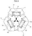
- FIG. 8 is a plan view showing the step of assembling the peripheral iron core portions, in the manufacturing process of a reactor according to a modification example of the embodiment. First, the coils ( 21 , 22 , and 23 ) are covered with the covering portions ( 31 , 32 , and 33 ), respectively.
- the covering portions ( 31 , 32 , and 33 ) are attached to the iron cores ( 101 , 102 , and 103 ) of the peripheral iron core portions ( 11 , 12 , and 13 ), respectively.
- the peripheral iron core portions ( 11 , 12 , and 13 ) are moved in the directions of the arrows of FIG. 8 , the first fitting part 41 is fitted onto the second fitting part 53 , the first fitting part 42 is fitted onto the second fitting part 51 , and the first fitting part 43 is fitted onto the second fitting part 52 .
- the structure of FIG. 1 is obtained.
- the peripheral iron core portions are assembled, after coupling the covering portions, thus enabling a reduction in manufacturing man-hour and ease of automation of the manufacturing process. Since the first fitting parts and the second fitting parts, which are provided in the covering portions, are fitted to each other, it is possible to obtain the secondary effect that the increased stiffness of the coils brings about a reduction in the influence of magnetic vibration and a reduction in noise.
- the casings for containing the coils are fitted to each other in the circumferential direction, it is possible to prevent an increase in manufacturing man-hour and an increase in difficulty in automation of the manufacturing process.
Landscapes
- Engineering & Computer Science (AREA)
- Power Engineering (AREA)
- Chemical & Material Sciences (AREA)
- Composite Materials (AREA)
- Insulating Of Coils (AREA)
- Coils Of Transformers For General Uses (AREA)
- Inverter Devices (AREA)
- Housings And Mounting Of Transformers (AREA)
Applications Claiming Priority (2)
| Application Number | Priority Date | Filing Date | Title |
|---|---|---|---|
| JP2017-133886 | 2017-07-07 | ||
| JP2017133886A JP6426796B1 (ja) | 2017-07-07 | 2017-07-07 | 互いに嵌合する機構を備えた被覆部を有するリアクトル |
Publications (2)
| Publication Number | Publication Date |
|---|---|
| US20190013134A1 US20190013134A1 (en) | 2019-01-10 |
| US10818423B2 true US10818423B2 (en) | 2020-10-27 |
Family
ID=64379281
Family Applications (1)
| Application Number | Title | Priority Date | Filing Date |
|---|---|---|---|
| US16/018,776 Active US10818423B2 (en) | 2017-07-07 | 2018-06-26 | Reactor having covering portions having fitting parts fitted to each other |
Country Status (4)
| Country | Link |
|---|---|
| US (1) | US10818423B2 (zh) |
| JP (1) | JP6426796B1 (zh) |
| CN (2) | CN109215988B (zh) |
| DE (1) | DE102018115941A1 (zh) |
Families Citing this family (5)
| Publication number | Priority date | Publication date | Assignee | Title |
|---|---|---|---|---|
| JP6450739B2 (ja) * | 2016-12-22 | 2019-01-09 | ファナック株式会社 | 電磁機器 |
| JP1590155S (zh) * | 2017-03-23 | 2017-11-06 | ||
| JP1590156S (zh) * | 2017-03-23 | 2017-11-06 | ||
| JP6426796B1 (ja) * | 2017-07-07 | 2018-11-21 | ファナック株式会社 | 互いに嵌合する機構を備えた被覆部を有するリアクトル |
| DE112021006430T5 (de) | 2021-05-20 | 2023-09-28 | Fanuc Corporation | Elektromagnetische Vorrichtung mit Spulengehäuse |
Citations (21)
| Publication number | Priority date | Publication date | Assignee | Title |
|---|---|---|---|---|
| US2406704A (en) * | 1941-11-04 | 1946-08-27 | Mossay Paul Alphonse Hubert | Multiphase alternating current transformer |
| DE2326294A1 (de) | 1972-05-24 | 1973-12-06 | Unelec | Magnetkreis fuer mehrphasentransformatoren |
| JPH02152210A (ja) | 1988-12-05 | 1990-06-12 | Nippondenso Co Ltd | 多気筒内燃機関用点火コイル |
| US5227745A (en) * | 1990-06-18 | 1993-07-13 | Matsushita Electric Industrial Co., Ltd. | Line filter assembly |
| JP2000077242A (ja) | 1998-08-31 | 2000-03-14 | Toshiba Tec Corp | 電磁機器 |
| US20040246089A1 (en) * | 2001-08-03 | 2004-12-09 | John Stephens | Dc to dc converters |
| US20060279392A1 (en) * | 2003-06-09 | 2006-12-14 | Minebea Co., Ltd. | Inverter transformer |
| JP2008210998A (ja) | 2007-02-27 | 2008-09-11 | Pony Denki Kk | エアギャップ付きリアクトル素子 |
| US20090261939A1 (en) | 2008-04-22 | 2009-10-22 | Todd Alexander Shudarek | Common mode, differential mode three phase inductor |
| CN201765902U (zh) | 2010-04-28 | 2011-03-16 | 成都深蓝高新技术发展有限公司 | 立式三角形铁心三相电抗器 |
| US20120106210A1 (en) | 2010-10-27 | 2012-05-03 | Rockwell Automation Technologies, Inc. | Multi-phase power converters and integrated choke therfor |
| US20120242444A1 (en) * | 2011-03-22 | 2012-09-27 | Delta Electronics, Inc. | Combined transformer |
| US20150102882A1 (en) | 2013-10-11 | 2015-04-16 | Mte Corporation | Adjustable integrated combined common mode and differential mode three phase inductors and methods of manufacture and use thereof |
| US20160125998A1 (en) | 2014-10-29 | 2016-05-05 | General Electric Company | Filter assembly and method |
| CN105742038A (zh) | 2014-12-26 | 2016-07-06 | Sht有限公司 | 共模扼流线圈 |
| US20170040099A1 (en) * | 2014-03-21 | 2017-02-09 | General Electric Company | Electromagnetic apparatus and method for providing the same |
| DE102016010901A1 (de) | 2015-09-17 | 2017-03-23 | Fanuc Corporation | Dreiphasen-Reaktor mit Eisenkerneinheiten und Spulen |
| JP2017059805A (ja) | 2015-09-17 | 2017-03-23 | ファナック株式会社 | 鉄心部およびコイルを備えた三相リアクトル |
| US20180234008A1 (en) * | 2015-10-16 | 2018-08-16 | Sma Solar Technology Ag | Inductor assembly and power supply system using the same |
| DE102018105659A1 (de) | 2017-03-17 | 2018-09-20 | Fanuc Corporation | Dreiphasen-drossel mit isolationsstruktur |
| US20190013134A1 (en) | 2017-07-07 | 2019-01-10 | Fanuc Corporation | Reactor having covering portions having fitting parts fitted to each other |
-
2017
- 2017-07-07 JP JP2017133886A patent/JP6426796B1/ja active Active
-
2018
- 2018-05-23 CN CN201810499937.6A patent/CN109215988B/zh active Active
- 2018-05-23 CN CN201820772477.5U patent/CN208460540U/zh active Active
- 2018-06-26 US US16/018,776 patent/US10818423B2/en active Active
- 2018-07-02 DE DE102018115941.2A patent/DE102018115941A1/de active Pending
Patent Citations (29)
| Publication number | Priority date | Publication date | Assignee | Title |
|---|---|---|---|---|
| US2406704A (en) * | 1941-11-04 | 1946-08-27 | Mossay Paul Alphonse Hubert | Multiphase alternating current transformer |
| DE2326294A1 (de) | 1972-05-24 | 1973-12-06 | Unelec | Magnetkreis fuer mehrphasentransformatoren |
| JPS4943123A (zh) | 1972-05-24 | 1974-04-23 | ||
| GB1415209A (en) * | 1972-05-24 | 1975-11-26 | Unelec | Magnetic core for a polyphase transformer |
| JPH02152210A (ja) | 1988-12-05 | 1990-06-12 | Nippondenso Co Ltd | 多気筒内燃機関用点火コイル |
| US5227745A (en) * | 1990-06-18 | 1993-07-13 | Matsushita Electric Industrial Co., Ltd. | Line filter assembly |
| JP2000077242A (ja) | 1998-08-31 | 2000-03-14 | Toshiba Tec Corp | 電磁機器 |
| US20040246089A1 (en) * | 2001-08-03 | 2004-12-09 | John Stephens | Dc to dc converters |
| US20060279392A1 (en) * | 2003-06-09 | 2006-12-14 | Minebea Co., Ltd. | Inverter transformer |
| JP2008210998A (ja) | 2007-02-27 | 2008-09-11 | Pony Denki Kk | エアギャップ付きリアクトル素子 |
| US20090261939A1 (en) | 2008-04-22 | 2009-10-22 | Todd Alexander Shudarek | Common mode, differential mode three phase inductor |
| CN201765902U (zh) | 2010-04-28 | 2011-03-16 | 成都深蓝高新技术发展有限公司 | 立式三角形铁心三相电抗器 |
| US20120106210A1 (en) | 2010-10-27 | 2012-05-03 | Rockwell Automation Technologies, Inc. | Multi-phase power converters and integrated choke therfor |
| US20120242444A1 (en) * | 2011-03-22 | 2012-09-27 | Delta Electronics, Inc. | Combined transformer |
| US20150102882A1 (en) | 2013-10-11 | 2015-04-16 | Mte Corporation | Adjustable integrated combined common mode and differential mode three phase inductors and methods of manufacture and use thereof |
| US20170040099A1 (en) * | 2014-03-21 | 2017-02-09 | General Electric Company | Electromagnetic apparatus and method for providing the same |
| US20160125998A1 (en) | 2014-10-29 | 2016-05-05 | General Electric Company | Filter assembly and method |
| CN105742038A (zh) | 2014-12-26 | 2016-07-06 | Sht有限公司 | 共模扼流线圈 |
| JP2016127121A (ja) | 2014-12-26 | 2016-07-11 | 株式会社エス・エッチ・ティ | コモンモードチョークコイル |
| EP3038117B1 (en) | 2014-12-26 | 2017-09-27 | SHT Corporation Limited | Common mode choke coil |
| US9646760B2 (en) | 2014-12-26 | 2017-05-09 | Sht Corporation Limited | Common mode choke coil |
| US20170084377A1 (en) | 2015-09-17 | 2017-03-23 | Fanuc Corporation | Three-phase reactor comprising iron-core units and coils |
| JP2017059805A (ja) | 2015-09-17 | 2017-03-23 | ファナック株式会社 | 鉄心部およびコイルを備えた三相リアクトル |
| DE102016010901A1 (de) | 2015-09-17 | 2017-03-23 | Fanuc Corporation | Dreiphasen-Reaktor mit Eisenkerneinheiten und Spulen |
| US20180234008A1 (en) * | 2015-10-16 | 2018-08-16 | Sma Solar Technology Ag | Inductor assembly and power supply system using the same |
| DE102018105659A1 (de) | 2017-03-17 | 2018-09-20 | Fanuc Corporation | Dreiphasen-drossel mit isolationsstruktur |
| US20180268992A1 (en) | 2017-03-17 | 2018-09-20 | Fanuc Corporation | Three-phase reactor having insulating structure |
| US20190013134A1 (en) | 2017-07-07 | 2019-01-10 | Fanuc Corporation | Reactor having covering portions having fitting parts fitted to each other |
| CN208460540U (zh) | 2017-07-07 | 2019-02-01 | 发那科株式会社 | 电抗器 |
Also Published As
| Publication number | Publication date |
|---|---|
| CN109215988B (zh) | 2021-08-31 |
| JP2019016711A (ja) | 2019-01-31 |
| CN208460540U (zh) | 2019-02-01 |
| DE102018115941A1 (de) | 2019-01-10 |
| CN109215988A (zh) | 2019-01-15 |
| JP6426796B1 (ja) | 2018-11-21 |
| US20190013134A1 (en) | 2019-01-10 |
Similar Documents
| Publication | Publication Date | Title |
|---|---|---|
| US10818423B2 (en) | Reactor having covering portions having fitting parts fitted to each other | |
| US10580565B2 (en) | Reactor including first end plate and second end plate | |
| US11004590B2 (en) | Reactor having iron cores and coils | |
| US20190035530A1 (en) | Reactor having core body interposed between end plate and pedestal | |
| US10714248B2 (en) | Reactor having outer peripheral iron core divided into multiple portions and production method therefor | |
| CN109300661B (zh) | 电抗器 | |
| US10937587B2 (en) | Reactor and method for production of core body | |
| US10784037B2 (en) | Reactor having temperature sensor attached to terminal base unit | |
| US10702848B2 (en) | Reactor including end plate including end plate formed of a plurality of end plate parts | |
| CN208507391U (zh) | 电抗器 | |
| CN107808732B (zh) | 电抗器 | |
| JP2018157094A (ja) | 絶縁構造を有する三相リアクトル | |
| US20180358165A1 (en) | Reactor having terminal and base | |
| JP6484068B2 (ja) | インダクタンス素子用樹脂ケースおよびインダクタンス素子 | |
| CN107017084B (zh) | 线圈装置 | |
| US11476033B2 (en) | Reactor provided with end plate | |
| KR101757480B1 (ko) | 유도 부품 | |
| US20240258022A1 (en) | Electromagnetic device provided with coil case | |
| JP6592209B2 (ja) | インダクタンス素子用樹脂ケースおよびインダクタンス素子 | |
| WO2022249411A1 (ja) | コイルケースを備えた電磁機器およびコイルケース | |
| JP7436226B2 (ja) | カバーを含むリアクトルおよびカバー | |
| JP2019004020A (ja) | 電力伝送コイル及び電力伝送コイルの製造方法 | |
| JP2018514949A (ja) | 誘導装置、コイルフォーマー及びその製造方法 |
Legal Events
| Date | Code | Title | Description |
|---|---|---|---|
| FEPP | Fee payment procedure |
Free format text: ENTITY STATUS SET TO UNDISCOUNTED (ORIGINAL EVENT CODE: BIG.); ENTITY STATUS OF PATENT OWNER: LARGE ENTITY |
|
| STPP | Information on status: patent application and granting procedure in general |
Free format text: APPLICATION DISPATCHED FROM PREEXAM, NOT YET DOCKETED |
|
| AS | Assignment |
Owner name: FANUC CORPORATION, JAPAN Free format text: ASSIGNMENT OF ASSIGNORS INTEREST;ASSIGNORS:YOSHIDA, TOMOKAZU;SHIROUZU, MASATOMO;TSUKADA, KENICHI;REEL/FRAME:047197/0917 Effective date: 20180508 |
|
| STPP | Information on status: patent application and granting procedure in general |
Free format text: DOCKETED NEW CASE - READY FOR EXAMINATION |
|
| AS | Assignment |
Owner name: FANUC CORPORATION, JAPAN Free format text: CORRECTIVE ASSIGNMENT TO CORRECT THE FILING DATE OF APPLICATION ON THE ASSIGNMENT DOCUMENT PREVIOUSLY RECORDED ON REEL 047197 FRAME 0917. ASSIGNOR(S) HEREBY CONFIRMS THE APPLICATION FILING DATE IS JUNE 26, 2018;ASSIGNORS:YOSHIDA, TOMOKAZU;SHIROUZU, MASATOMO;TSUKADA, KENICHI;REEL/FRAME:049927/0273 Effective date: 20180508 |
|
| STPP | Information on status: patent application and granting procedure in general |
Free format text: NON FINAL ACTION MAILED |
|
| STPP | Information on status: patent application and granting procedure in general |
Free format text: RESPONSE TO NON-FINAL OFFICE ACTION ENTERED AND FORWARDED TO EXAMINER |
|
| STPP | Information on status: patent application and granting procedure in general |
Free format text: FINAL REJECTION MAILED |
|
| AS | Assignment |
Owner name: FANUC CORPORATION, JAPAN Free format text: CORRECTIVE ASSIGNMENT TO CORRECT THE ASSIGNMENT AGREEMENT FILING DATE TO JUNE 26, 2018 PREVIOUSLY RECORDED AT REEL: 047197 FRAME: 0917. ASSIGNOR(S) HEREBY CONFIRMS THE ASSIGNMENT;ASSIGNORS:YOSHIDA, TOMOKAZU;SHIROUZU, MASATOMO;TSUKADA, KENICHI;REEL/FRAME:052134/0447 Effective date: 20180508 |
|
| STPP | Information on status: patent application and granting procedure in general |
Free format text: RESPONSE AFTER FINAL ACTION FORWARDED TO EXAMINER |
|
| STPP | Information on status: patent application and granting procedure in general |
Free format text: DOCKETED NEW CASE - READY FOR EXAMINATION |
|
| STPP | Information on status: patent application and granting procedure in general |
Free format text: NOTICE OF ALLOWANCE MAILED -- APPLICATION RECEIVED IN OFFICE OF PUBLICATIONS |
|
| STCF | Information on status: patent grant |
Free format text: PATENTED CASE |
|
| MAFP | Maintenance fee payment |
Free format text: PAYMENT OF MAINTENANCE FEE, 4TH YEAR, LARGE ENTITY (ORIGINAL EVENT CODE: M1551); ENTITY STATUS OF PATENT OWNER: LARGE ENTITY Year of fee payment: 4 |