US10752836B2 - Phosphor - Google Patents
Phosphor Download PDFInfo
- Publication number
- US10752836B2 US10752836B2 US15/572,449 US201615572449A US10752836B2 US 10752836 B2 US10752836 B2 US 10752836B2 US 201615572449 A US201615572449 A US 201615572449A US 10752836 B2 US10752836 B2 US 10752836B2
- Authority
- US
- United States
- Prior art keywords
- phosphor
- lial
- red
- inorganic compound
- emitting
- Prior art date
- Legal status (The legal status is an assumption and is not a legal conclusion. Google has not performed a legal analysis and makes no representation as to the accuracy of the status listed.)
- Active, expires
Links
- OAICVXFJPJFONN-UHFFFAOYSA-N Phosphorus Chemical compound [P] OAICVXFJPJFONN-UHFFFAOYSA-N 0.000 title claims abstract description 340
- 150000002484 inorganic compounds Chemical class 0.000 claims abstract description 47
- 229910010272 inorganic material Inorganic materials 0.000 claims abstract description 47
- 239000013078 crystal Substances 0.000 claims abstract description 45
- 229910052744 lithium Inorganic materials 0.000 claims abstract description 15
- 229910052748 manganese Inorganic materials 0.000 claims abstract description 15
- 229910052693 Europium Inorganic materials 0.000 claims abstract description 13
- 229910052769 Ytterbium Inorganic materials 0.000 claims abstract description 13
- 229910052700 potassium Inorganic materials 0.000 claims abstract description 13
- 229910052777 Praseodymium Inorganic materials 0.000 claims abstract description 12
- 229910052708 sodium Inorganic materials 0.000 claims abstract description 12
- 229910052792 caesium Inorganic materials 0.000 claims abstract description 11
- 229910052804 chromium Inorganic materials 0.000 claims abstract description 11
- 229910052701 rubidium Inorganic materials 0.000 claims abstract description 11
- 229910052692 Dysprosium Inorganic materials 0.000 claims abstract description 10
- 229910052691 Erbium Inorganic materials 0.000 claims abstract description 10
- 229910052689 Holmium Inorganic materials 0.000 claims abstract description 10
- 229910052779 Neodymium Inorganic materials 0.000 claims abstract description 10
- 229910052772 Samarium Inorganic materials 0.000 claims abstract description 10
- 229910052771 Terbium Inorganic materials 0.000 claims abstract description 10
- 229910052775 Thulium Inorganic materials 0.000 claims abstract description 10
- 239000000843 powder Substances 0.000 claims description 45
- 238000000034 method Methods 0.000 claims description 37
- 239000000203 mixture Substances 0.000 claims description 32
- 229910010084 LiAlH4 Inorganic materials 0.000 claims description 31
- 239000012280 lithium aluminium hydride Substances 0.000 claims description 31
- IDBFBDSKYCUNPW-UHFFFAOYSA-N lithium nitride Chemical compound [Li]N([Li])[Li] IDBFBDSKYCUNPW-UHFFFAOYSA-N 0.000 claims description 31
- 238000006243 chemical reaction Methods 0.000 claims description 28
- 229910016653 EuF3 Inorganic materials 0.000 claims description 27
- 230000005855 radiation Effects 0.000 claims description 27
- 239000007858 starting material Substances 0.000 claims description 26
- 229910052712 strontium Inorganic materials 0.000 claims description 24
- 229910052791 calcium Inorganic materials 0.000 claims description 22
- -1 Sr3N2 Chemical compound 0.000 claims description 17
- 238000001816 cooling Methods 0.000 claims description 16
- 238000010438 heat treatment Methods 0.000 claims description 12
- 238000000137 annealing Methods 0.000 claims description 10
- 238000004519 manufacturing process Methods 0.000 claims description 6
- 238000002156 mixing Methods 0.000 claims description 4
- 239000012190 activator Substances 0.000 abstract description 9
- 238000001228 spectrum Methods 0.000 description 24
- 239000004065 semiconductor Substances 0.000 description 14
- 238000000295 emission spectrum Methods 0.000 description 13
- 229910052788 barium Inorganic materials 0.000 description 10
- 230000003595 spectral effect Effects 0.000 description 10
- 238000010521 absorption reaction Methods 0.000 description 9
- 150000001875 compounds Chemical class 0.000 description 9
- 238000006467 substitution reaction Methods 0.000 description 9
- RYGMFSIKBFXOCR-UHFFFAOYSA-N Copper Chemical compound [Cu] RYGMFSIKBFXOCR-UHFFFAOYSA-N 0.000 description 8
- 229910052802 copper Inorganic materials 0.000 description 8
- 239000010949 copper Substances 0.000 description 8
- 230000000717 retained effect Effects 0.000 description 7
- 239000007789 gas Substances 0.000 description 6
- 239000000463 material Substances 0.000 description 6
- RKTYLMNFRDHKIL-UHFFFAOYSA-N copper;5,10,15,20-tetraphenylporphyrin-22,24-diide Chemical compound [Cu+2].C1=CC(C(=C2C=CC([N-]2)=C(C=2C=CC=CC=2)C=2C=CC(N=2)=C(C=2C=CC=CC=2)C2=CC=C3[N-]2)C=2C=CC=CC=2)=NC1=C3C1=CC=CC=C1 RKTYLMNFRDHKIL-UHFFFAOYSA-N 0.000 description 5
- 238000002474 experimental method Methods 0.000 description 5
- 229910052751 metal Inorganic materials 0.000 description 5
- 239000002184 metal Substances 0.000 description 5
- 150000002739 metals Chemical class 0.000 description 5
- 238000004382 potting Methods 0.000 description 5
- 229910010220 LiAl4 Inorganic materials 0.000 description 4
- CPLXHLVBOLITMK-UHFFFAOYSA-N Magnesium oxide Chemical compound [Mg]=O CPLXHLVBOLITMK-UHFFFAOYSA-N 0.000 description 4
- XLOMVQKBTHCTTD-UHFFFAOYSA-N Zinc monoxide Chemical compound [Zn]=O XLOMVQKBTHCTTD-UHFFFAOYSA-N 0.000 description 4
- 229910052782 aluminium Inorganic materials 0.000 description 4
- 230000006870 function Effects 0.000 description 4
- 229910052749 magnesium Inorganic materials 0.000 description 4
- 229910052760 oxygen Inorganic materials 0.000 description 4
- 229910052717 sulfur Inorganic materials 0.000 description 4
- WFKWXMTUELFFGS-UHFFFAOYSA-N tungsten Chemical compound [W] WFKWXMTUELFFGS-UHFFFAOYSA-N 0.000 description 4
- 229910052721 tungsten Inorganic materials 0.000 description 4
- 239000010937 tungsten Substances 0.000 description 4
- 229910052684 Cerium Inorganic materials 0.000 description 3
- 239000008240 homogeneous mixture Substances 0.000 description 3
- 229910052725 zinc Inorganic materials 0.000 description 3
- IJGRMHOSHXDMSA-UHFFFAOYSA-N Atomic nitrogen Chemical compound N#N IJGRMHOSHXDMSA-UHFFFAOYSA-N 0.000 description 2
- 229910002601 GaN Inorganic materials 0.000 description 2
- JMASRVWKEDWRBT-UHFFFAOYSA-N Gallium nitride Chemical compound [Ga]#N JMASRVWKEDWRBT-UHFFFAOYSA-N 0.000 description 2
- 229910010199 LiAl Inorganic materials 0.000 description 2
- 229910017639 MgSi Inorganic materials 0.000 description 2
- VYPSYNLAJGMNEJ-UHFFFAOYSA-N Silicium dioxide Chemical compound O=[Si]=O VYPSYNLAJGMNEJ-UHFFFAOYSA-N 0.000 description 2
- 238000002441 X-ray diffraction Methods 0.000 description 2
- 229910052796 boron Inorganic materials 0.000 description 2
- 229910052794 bromium Inorganic materials 0.000 description 2
- 229910052799 carbon Inorganic materials 0.000 description 2
- 229910019990 cerium-doped yttrium aluminum garnet Inorganic materials 0.000 description 2
- 229910052801 chlorine Inorganic materials 0.000 description 2
- 238000002447 crystallographic data Methods 0.000 description 2
- 238000010586 diagram Methods 0.000 description 2
- 229910052731 fluorine Inorganic materials 0.000 description 2
- 229910052733 gallium Inorganic materials 0.000 description 2
- 239000012535 impurity Substances 0.000 description 2
- 229910052740 iodine Inorganic materials 0.000 description 2
- 229910052746 lanthanum Inorganic materials 0.000 description 2
- 238000004020 luminiscence type Methods 0.000 description 2
- 229910052759 nickel Inorganic materials 0.000 description 2
- 229910052757 nitrogen Inorganic materials 0.000 description 2
- 229910052706 scandium Inorganic materials 0.000 description 2
- 230000035945 sensitivity Effects 0.000 description 2
- 229910052727 yttrium Inorganic materials 0.000 description 2
- UFHFLCQGNIYNRP-UHFFFAOYSA-N Hydrogen Chemical compound [H][H] UFHFLCQGNIYNRP-UHFFFAOYSA-N 0.000 description 1
- FUJCRWPEOMXPAD-UHFFFAOYSA-N Li2O Inorganic materials [Li+].[Li+].[O-2] FUJCRWPEOMXPAD-UHFFFAOYSA-N 0.000 description 1
- 238000003991 Rietveld refinement Methods 0.000 description 1
- 229910052581 Si3N4 Inorganic materials 0.000 description 1
- 229910007379 Zn3N2 Inorganic materials 0.000 description 1
- JNDMLEXHDPKVFC-UHFFFAOYSA-N aluminum;oxygen(2-);yttrium(3+) Chemical compound [O-2].[O-2].[O-2].[Al+3].[Y+3] JNDMLEXHDPKVFC-UHFFFAOYSA-N 0.000 description 1
- DSAJWYNOEDNPEQ-UHFFFAOYSA-N barium atom Chemical compound [Ba] DSAJWYNOEDNPEQ-UHFFFAOYSA-N 0.000 description 1
- ZMIGMASIKSOYAM-UHFFFAOYSA-N cerium Chemical compound [Ce][Ce][Ce][Ce][Ce][Ce][Ce][Ce][Ce][Ce][Ce][Ce][Ce][Ce][Ce][Ce][Ce][Ce][Ce][Ce][Ce][Ce][Ce][Ce][Ce][Ce][Ce][Ce][Ce][Ce][Ce][Ce][Ce][Ce][Ce][Ce][Ce][Ce] ZMIGMASIKSOYAM-UHFFFAOYSA-N 0.000 description 1
- 229910052681 coesite Inorganic materials 0.000 description 1
- 229910052906 cristobalite Inorganic materials 0.000 description 1
- 238000000354 decomposition reaction Methods 0.000 description 1
- 238000011161 development Methods 0.000 description 1
- 230000018109 developmental process Effects 0.000 description 1
- XUCJHNOBJLKZNU-UHFFFAOYSA-M dilithium;hydroxide Chemical compound [Li+].[Li+].[OH-] XUCJHNOBJLKZNU-UHFFFAOYSA-M 0.000 description 1
- 238000006073 displacement reaction Methods 0.000 description 1
- 230000001747 exhibiting effect Effects 0.000 description 1
- 238000001914 filtration Methods 0.000 description 1
- 229910052739 hydrogen Inorganic materials 0.000 description 1
- 239000001257 hydrogen Substances 0.000 description 1
- 229910052738 indium Inorganic materials 0.000 description 1
- APFVFJFRJDLVQX-UHFFFAOYSA-N indium atom Chemical compound [In] APFVFJFRJDLVQX-UHFFFAOYSA-N 0.000 description 1
- XGZVUEUWXADBQD-UHFFFAOYSA-L lithium carbonate Chemical compound [Li+].[Li+].[O-]C([O-])=O XGZVUEUWXADBQD-UHFFFAOYSA-L 0.000 description 1
- 229910052808 lithium carbonate Inorganic materials 0.000 description 1
- 230000007774 longterm Effects 0.000 description 1
- 238000005259 measurement Methods 0.000 description 1
- 230000008447 perception Effects 0.000 description 1
- 239000000377 silicon dioxide Substances 0.000 description 1
- 239000007787 solid Substances 0.000 description 1
- 229910052682 stishovite Inorganic materials 0.000 description 1
- CIOAGBVUUVVLOB-UHFFFAOYSA-N strontium atom Chemical compound [Sr] CIOAGBVUUVVLOB-UHFFFAOYSA-N 0.000 description 1
- 229910052905 tridymite Inorganic materials 0.000 description 1
- 229910019901 yttrium aluminum garnet Inorganic materials 0.000 description 1
Images


Classifications
-
- C—CHEMISTRY; METALLURGY
- C09—DYES; PAINTS; POLISHES; NATURAL RESINS; ADHESIVES; COMPOSITIONS NOT OTHERWISE PROVIDED FOR; APPLICATIONS OF MATERIALS NOT OTHERWISE PROVIDED FOR
- C09K—MATERIALS FOR MISCELLANEOUS APPLICATIONS, NOT PROVIDED FOR ELSEWHERE
- C09K11/00—Luminescent, e.g. electroluminescent, chemiluminescent materials
- C09K11/08—Luminescent, e.g. electroluminescent, chemiluminescent materials containing inorganic luminescent materials
- C09K11/77—Luminescent, e.g. electroluminescent, chemiluminescent materials containing inorganic luminescent materials containing rare earth metals
- C09K11/7728—Luminescent, e.g. electroluminescent, chemiluminescent materials containing inorganic luminescent materials containing rare earth metals containing europium
- C09K11/7734—Aluminates
-
- C—CHEMISTRY; METALLURGY
- C09—DYES; PAINTS; POLISHES; NATURAL RESINS; ADHESIVES; COMPOSITIONS NOT OTHERWISE PROVIDED FOR; APPLICATIONS OF MATERIALS NOT OTHERWISE PROVIDED FOR
- C09K—MATERIALS FOR MISCELLANEOUS APPLICATIONS, NOT PROVIDED FOR ELSEWHERE
- C09K11/00—Luminescent, e.g. electroluminescent, chemiluminescent materials
- C09K11/08—Luminescent, e.g. electroluminescent, chemiluminescent materials containing inorganic luminescent materials
- C09K11/0883—Arsenides; Nitrides; Phosphides
-
- C—CHEMISTRY; METALLURGY
- C01—INORGANIC CHEMISTRY
- C01B—NON-METALLIC ELEMENTS; COMPOUNDS THEREOF; METALLOIDS OR COMPOUNDS THEREOF NOT COVERED BY SUBCLASS C01C
- C01B21/00—Nitrogen; Compounds thereof
- C01B21/06—Binary compounds of nitrogen with metals, with silicon, or with boron, or with carbon, i.e. nitrides; Compounds of nitrogen with more than one metal, silicon or boron
- C01B21/0602—Binary compounds of nitrogen with metals, with silicon, or with boron, or with carbon, i.e. nitrides; Compounds of nitrogen with more than one metal, silicon or boron with two or more other elements chosen from metals, silicon or boron
-
- C—CHEMISTRY; METALLURGY
- C04—CEMENTS; CONCRETE; ARTIFICIAL STONE; CERAMICS; REFRACTORIES
- C04B—LIME, MAGNESIA; SLAG; CEMENTS; COMPOSITIONS THEREOF, e.g. MORTARS, CONCRETE OR LIKE BUILDING MATERIALS; ARTIFICIAL STONE; CERAMICS; REFRACTORIES; TREATMENT OF NATURAL STONE
- C04B35/00—Shaped ceramic products characterised by their composition; Ceramics compositions; Processing powders of inorganic compounds preparatory to the manufacturing of ceramic products
- C04B35/515—Shaped ceramic products characterised by their composition; Ceramics compositions; Processing powders of inorganic compounds preparatory to the manufacturing of ceramic products based on non-oxide ceramics
- C04B35/58—Shaped ceramic products characterised by their composition; Ceramics compositions; Processing powders of inorganic compounds preparatory to the manufacturing of ceramic products based on non-oxide ceramics based on borides, nitrides, i.e. nitrides, oxynitrides, carbonitrides or oxycarbonitrides or silicides
- C04B35/581—Shaped ceramic products characterised by their composition; Ceramics compositions; Processing powders of inorganic compounds preparatory to the manufacturing of ceramic products based on non-oxide ceramics based on borides, nitrides, i.e. nitrides, oxynitrides, carbonitrides or oxycarbonitrides or silicides based on aluminium nitride
-
- C—CHEMISTRY; METALLURGY
- C04—CEMENTS; CONCRETE; ARTIFICIAL STONE; CERAMICS; REFRACTORIES
- C04B—LIME, MAGNESIA; SLAG; CEMENTS; COMPOSITIONS THEREOF, e.g. MORTARS, CONCRETE OR LIKE BUILDING MATERIALS; ARTIFICIAL STONE; CERAMICS; REFRACTORIES; TREATMENT OF NATURAL STONE
- C04B35/00—Shaped ceramic products characterised by their composition; Ceramics compositions; Processing powders of inorganic compounds preparatory to the manufacturing of ceramic products
- C04B35/622—Forming processes; Processing powders of inorganic compounds preparatory to the manufacturing of ceramic products
- C04B35/626—Preparing or treating the powders individually or as batches ; preparing or treating macroscopic reinforcing agents for ceramic products, e.g. fibres; mechanical aspects section B
- C04B35/62605—Treating the starting powders individually or as mixtures
- C04B35/62645—Thermal treatment of powders or mixtures thereof other than sintering
- C04B35/6268—Thermal treatment of powders or mixtures thereof other than sintering characterised by the applied pressure or type of atmosphere, e.g. in vacuum, hydrogen or a specific oxygen pressure
-
- C—CHEMISTRY; METALLURGY
- C09—DYES; PAINTS; POLISHES; NATURAL RESINS; ADHESIVES; COMPOSITIONS NOT OTHERWISE PROVIDED FOR; APPLICATIONS OF MATERIALS NOT OTHERWISE PROVIDED FOR
- C09K—MATERIALS FOR MISCELLANEOUS APPLICATIONS, NOT PROVIDED FOR ELSEWHERE
- C09K11/00—Luminescent, e.g. electroluminescent, chemiluminescent materials
- C09K11/08—Luminescent, e.g. electroluminescent, chemiluminescent materials containing inorganic luminescent materials
- C09K11/77—Luminescent, e.g. electroluminescent, chemiluminescent materials containing inorganic luminescent materials containing rare earth metals
- C09K11/7728—Luminescent, e.g. electroluminescent, chemiluminescent materials containing inorganic luminescent materials containing rare earth metals containing europium
- C09K11/77346—Aluminium Nitrides or Aluminium Oxynitrides
-
- H—ELECTRICITY
- H01—ELECTRIC ELEMENTS
- H01L—SEMICONDUCTOR DEVICES NOT COVERED BY CLASS H10
- H01L33/00—Semiconductor devices having potential barriers specially adapted for light emission; Processes or apparatus specially adapted for the manufacture or treatment thereof or of parts thereof; Details thereof
- H01L33/48—Semiconductor devices having potential barriers specially adapted for light emission; Processes or apparatus specially adapted for the manufacture or treatment thereof or of parts thereof; Details thereof characterised by the semiconductor body packages
- H01L33/50—Wavelength conversion elements
- H01L33/501—Wavelength conversion elements characterised by the materials, e.g. binder
- H01L33/502—Wavelength conversion materials
-
- C—CHEMISTRY; METALLURGY
- C04—CEMENTS; CONCRETE; ARTIFICIAL STONE; CERAMICS; REFRACTORIES
- C04B—LIME, MAGNESIA; SLAG; CEMENTS; COMPOSITIONS THEREOF, e.g. MORTARS, CONCRETE OR LIKE BUILDING MATERIALS; ARTIFICIAL STONE; CERAMICS; REFRACTORIES; TREATMENT OF NATURAL STONE
- C04B2235/00—Aspects relating to ceramic starting mixtures or sintered ceramic products
- C04B2235/02—Composition of constituents of the starting material or of secondary phases of the final product
- C04B2235/30—Constituents and secondary phases not being of a fibrous nature
- C04B2235/32—Metal oxides, mixed metal oxides, or oxide-forming salts thereof, e.g. carbonates, nitrates, (oxy)hydroxides, chlorides
- C04B2235/3201—Alkali metal oxides or oxide-forming salts thereof
- C04B2235/3203—Lithium oxide or oxide-forming salts thereof
-
- C—CHEMISTRY; METALLURGY
- C04—CEMENTS; CONCRETE; ARTIFICIAL STONE; CERAMICS; REFRACTORIES
- C04B—LIME, MAGNESIA; SLAG; CEMENTS; COMPOSITIONS THEREOF, e.g. MORTARS, CONCRETE OR LIKE BUILDING MATERIALS; ARTIFICIAL STONE; CERAMICS; REFRACTORIES; TREATMENT OF NATURAL STONE
- C04B2235/00—Aspects relating to ceramic starting mixtures or sintered ceramic products
- C04B2235/02—Composition of constituents of the starting material or of secondary phases of the final product
- C04B2235/30—Constituents and secondary phases not being of a fibrous nature
- C04B2235/32—Metal oxides, mixed metal oxides, or oxide-forming salts thereof, e.g. carbonates, nitrates, (oxy)hydroxides, chlorides
- C04B2235/3217—Aluminum oxide or oxide forming salts thereof, e.g. bauxite, alpha-alumina
-
- C—CHEMISTRY; METALLURGY
- C04—CEMENTS; CONCRETE; ARTIFICIAL STONE; CERAMICS; REFRACTORIES
- C04B—LIME, MAGNESIA; SLAG; CEMENTS; COMPOSITIONS THEREOF, e.g. MORTARS, CONCRETE OR LIKE BUILDING MATERIALS; ARTIFICIAL STONE; CERAMICS; REFRACTORIES; TREATMENT OF NATURAL STONE
- C04B2235/00—Aspects relating to ceramic starting mixtures or sintered ceramic products
- C04B2235/02—Composition of constituents of the starting material or of secondary phases of the final product
- C04B2235/30—Constituents and secondary phases not being of a fibrous nature
- C04B2235/32—Metal oxides, mixed metal oxides, or oxide-forming salts thereof, e.g. carbonates, nitrates, (oxy)hydroxides, chlorides
- C04B2235/3224—Rare earth oxide or oxide forming salts thereof, e.g. scandium oxide
-
- C—CHEMISTRY; METALLURGY
- C04—CEMENTS; CONCRETE; ARTIFICIAL STONE; CERAMICS; REFRACTORIES
- C04B—LIME, MAGNESIA; SLAG; CEMENTS; COMPOSITIONS THEREOF, e.g. MORTARS, CONCRETE OR LIKE BUILDING MATERIALS; ARTIFICIAL STONE; CERAMICS; REFRACTORIES; TREATMENT OF NATURAL STONE
- C04B2235/00—Aspects relating to ceramic starting mixtures or sintered ceramic products
- C04B2235/02—Composition of constituents of the starting material or of secondary phases of the final product
- C04B2235/30—Constituents and secondary phases not being of a fibrous nature
- C04B2235/38—Non-oxide ceramic constituents or additives
- C04B2235/3852—Nitrides, e.g. oxynitrides, carbonitrides, oxycarbonitrides, lithium nitride, magnesium nitride
- C04B2235/3865—Aluminium nitrides
-
- C—CHEMISTRY; METALLURGY
- C04—CEMENTS; CONCRETE; ARTIFICIAL STONE; CERAMICS; REFRACTORIES
- C04B—LIME, MAGNESIA; SLAG; CEMENTS; COMPOSITIONS THEREOF, e.g. MORTARS, CONCRETE OR LIKE BUILDING MATERIALS; ARTIFICIAL STONE; CERAMICS; REFRACTORIES; TREATMENT OF NATURAL STONE
- C04B2235/00—Aspects relating to ceramic starting mixtures or sintered ceramic products
- C04B2235/02—Composition of constituents of the starting material or of secondary phases of the final product
- C04B2235/30—Constituents and secondary phases not being of a fibrous nature
- C04B2235/44—Metal salt constituents or additives chosen for the nature of the anions, e.g. hydrides or acetylacetonate
- C04B2235/444—Halide containing anions, e.g. bromide, iodate, chlorite
- C04B2235/445—Fluoride containing anions, e.g. fluosilicate
-
- C—CHEMISTRY; METALLURGY
- C04—CEMENTS; CONCRETE; ARTIFICIAL STONE; CERAMICS; REFRACTORIES
- C04B—LIME, MAGNESIA; SLAG; CEMENTS; COMPOSITIONS THEREOF, e.g. MORTARS, CONCRETE OR LIKE BUILDING MATERIALS; ARTIFICIAL STONE; CERAMICS; REFRACTORIES; TREATMENT OF NATURAL STONE
- C04B2235/00—Aspects relating to ceramic starting mixtures or sintered ceramic products
- C04B2235/70—Aspects relating to sintered or melt-casted ceramic products
- C04B2235/74—Physical characteristics
- C04B2235/76—Crystal structural characteristics, e.g. symmetry
- C04B2235/761—Unit-cell parameters, e.g. lattice constants
Definitions
- the invention relates to a phosphor, a method for producing a phosphor, use of a phosphor in a conversion element and use of a phosphor for the conversion of light.
- the emission wavelength may be shifted from the orange into the red region of the spectrum by replacing barium with strontium.
- this replacement results in a reduction in the long-term stability of the phosphor.
- (Sr,Ba) 2 Si 5 N 8 :Eu 2+ phosphors additionally exhibit large half-value widths and do not exhibit any emission in the dark red region of the spectrum, i.e., no emission at a dominant wavelength of over 620 nm.
- the phosphor (Sr,Ca)AlSiN 3 :Eu 2+ already exhibits emission in the dark red region of the spectrum, it exhibits very broad emission, which extends into the non-visible region of the electromagnetic spectrum, whereby the luminescence efficiency of this phosphor is reduced. There is therefore considerable demand for a phosphor which exhibits emission in the dark red region of the electromagnetic spectrum and a small half-value width and thereby little emission outside the visible region of the electromagnetic spectrum.
- WO 2013/175336 A1 and Nature Materials 2014, P. Pust et al., “Narrow-band red emitting Sr[LiAl 3 N 4 ]:Eu 2+ as a next-generation LED-phosphor material” disclose a phosphor of the formula SrLiAl 3 N 4 :Eu 2+ which already has an emission in the dark red region of the electromagnetic spectrum and a small half-value width, said phosphor additionally exhibiting little emission outside the visible region of the electromagnetic spectrum.
- the phosphor has a lower quantum efficiency, i.e., a poor ratio between the number of emitted and absorbed photons, compared with (Sr,Ba) 2 Si 5 N 8 :Eu 2+ and (Sr,Ca)AlSiN 3 :Eu 2+ .
- Embodiments provide a phosphor which has less emission outside the visible region of the electromagnetic spectrum, exhibits a small half-value width and additionally has high quantum efficiency. Further embodiments provide an efficient method for producing a phosphor, use of a phosphor in a conversion element and use of a phosphor for the conversion of light.
- a phosphor is provided.
- the phosphor comprises an inorganic compound, which comprises at least one activator E and N and/or O in its empirical formula.
- the activator E is here from a group comprising Mn, Cr, Ni, Ce, Pr, Nd, Sm, Eu, Tb, Dy, Ho, Er, Yb, Tm, Li, Na, K, Rb, Cs and combinations thereof.
- the activator E is responsible for the wavelength of the emitted radiation of the phosphor.
- E is equal to Eu in combination with one, two or more further elements E, preferably selected from Mn or Li.
- E Eu, preferably Eu 2+ .
- the phosphor consists of the inorganic compound.
- the phosphor then comprises at least one activator E and N and/or O in its empirical formula, wherein E is selected from a group comprising Mn, Cr, Ni, Ce, Pr, Nd, Sm, Eu, Tb, Dy, Ho, Er, Yb, Tm, Li, Na, K, Rb, Cs and combinations thereof.
- the phosphor may comprise different phases, inter alia the inorganic compound, or it may consist of one or more further phases and the inorganic compound.
- the inorganic compound crystallizes in a crystal structure with the same atomic sequence as in K 2 Zn 6 O 7 .
- the fact that the inorganic compound crystallizes in a crystal structure with the same atomic sequence as in K 2 Zn 6 O 7 means here and hereinafter that the sequence of atoms of the inorganic compound follows the same pattern as the sequence of atoms in K 2 Zn 6 O 7 .
- the crystal structure has the same structural motifs as K 2 Zn 6 O 7 .
- the inorganic compound or the phosphor follows the empirical formula (Sr,Eu) 2 (Li 0.5 Al 5.5 )N 7 , Sr and Eu occupy the sites of K, Li and Al occupy the sites of Zn and N occupies the sites of O in K 2 Zn 6 O 7 .
- the inorganic compound or the phosphor is described in the orthorhombic space group space group Pnnm.
- lattice parameter c is in particular in the range from 3.21-3.29 ⁇
- lattice parameter a in the range from 10.24-10.43 ⁇
- lattice parameter b in the range from 10.29-10.43 ⁇ .
- the crystal structure may also be described in a tetragonal crystal system due to twinning and pseudosymmetry. Descriptions in other space groups are also possible.
- the inorganic compound comprises N and/or O in its empirical formula.
- z 0.
- This embodiment thus relates to an electroneutral inorganic compound or an electroneutral phosphor.
- the phosphor is thus very stable and may be used for the most varied of applications.
- the phosphor is in particular suitable for application in a light-emitting diode, since it exhibits stable and uniform emission over the service life of the light-emitting diode.
- the inorganic compound or the phosphor comprises one of the following empirical formulae: M 4 Li 1+y′/2 Al 11 ⁇ y′/2 N 14-y′ O y′ :E, M 4 Li 1 ⁇ z′ Al 11 ⁇ z′ Zn 2z N 14 :E, M 4 LiAl 11 ⁇ x′ Zn x′ N 14 ⁇ x′ O x′ :E, M 4 LiAl 11 ⁇ y′′ Mg y′′ N 14 ⁇ y′′ O y′′ :E, M 4 Li 1+z′′ Al 11 ⁇ 3z′′ Si 2z′′ N 14 :E or M 4 LiAl 11 ⁇ 2x′′ Si x′′ Mg x′′ N 14 :E.
- M Ca, Sr and/or Ba, 0 ⁇ y′ ⁇ 14, 0 ⁇ z′ ⁇ 1, 0 ⁇ x′ ⁇ 11, 0 ⁇ y′′ ⁇ 11, 0 ⁇ z′′ ⁇ 3 and 0 ⁇ x′′ ⁇ 5.
- E in particular replaces M in the empirical formula and occupies the lattice sites of M.
- the inorganic compound or the phosphor comprises one of the following empirical formulae: M 4 ⁇ x Eu x Li 1+y′/2 Al 11 ⁇ y′/2 N 14 ⁇ y′ O y′ , M 4 ⁇ x Eu x Li 1 ⁇ z′ Al 11 ⁇ z′ Zn 2z′ N 14 , M 4 ⁇ x Eu x LiAl 11 ⁇ x′ Zn x′ N 14 ⁇ x′ O x′ , M 4 ⁇ x Eu x LiAl 11 ⁇ y′′ Mg y′′ N 14 ⁇ y′′ O y′′ , M 4 ⁇ x Eu x Li 1+z′′ Al 11 ⁇ 3z′′ Si 2z′′ N 14 or M 4 ⁇ x Eu x LiAl 11 ⁇ 2x′′ Si x′′ Mg x′′ N 14 .
- M Ca, Sr and/or Ba, and 0 ⁇ y′ ⁇ 14, 0 ⁇ z′ ⁇ 1, 0 ⁇ x′ ⁇ 11, 0 ⁇ y′′ ⁇ 11, 0 ⁇ z′′ ⁇ 3, 0 ⁇ x′′ ⁇ 5 and 0 ⁇ x ⁇ 2.
- 0.001 ⁇ x ⁇ 0.4 particularly preferably 0.01 ⁇ x ⁇ 0.2.
- Eu or Eu 2+ ions in this case in particular replace M and occupy the lattice sites of M.
- AlN 2 may be replaced in part by LiO 2 . Surprisingly, the crystal structure is retained, while the spectral position and thus the peak wavelength of the phosphor shifts.
- the peak wavelength is shifted to shorter wavelengths.
- the result is the following empirical formulae: M 4 ⁇ x Eu x LiAl 11 N 14 , (M 4 ⁇ x Eu x ) 2 Li 3 Al 21 n 26 O 2 , (M 4 ⁇ x Eu x ) 0.5 LiAl 5 N 6 O, (M 4 ⁇ x Eu x ) 2 Li 5 Al 19 N 22 O 6 , M 4 ⁇ x Eu x Li 3 Al 9 N 10 O 4 , (M 4 ⁇ x Eu x ) 2 Li 7 Al 17 N 18 O 10 , (M 4 ⁇ x Eu x ) 0.5 Li 2 Al 4 N 4 O 3 , (M 4 ⁇ x Eu x ) 2 Li 9 Al 15 N 14 O 14 , M 4 ⁇ x Eu x Li 5 Al 7 N 6 O 8 , (M 4 ⁇ x Eu x ) 2 Li 11 Al 13 N 10 O 18 , (M 4 ⁇ x Eu x ) 0.5 Li 3 Al 3 N 2 O 5 , (M 4 ⁇ x Eu x ) 2 Li 13
- M 4 ⁇ x Eu x LiAl 11 N 14 in this embodiment LiAl may be replaced in part by Zn 2 . Surprisingly, the crystal structure is retained, while the spectral position and thus the peak wavelength of the phosphor may shift.
- AlN may be replaced in part by ZnO.
- the crystal structure is retained, while the spectral position and thus the peak wavelength of the phosphor shifts. In particular, the peak wavelength is shifted to shorter wavelengths.
- the result is the following empirical formulae: M 4 ⁇ x Eu x LiAl 11 N 14 , M 4 ⁇ x Eu x LiAl 10 Zn 1 N 13 O, M 4 ⁇ x Eu x LiAl 9 Zn 2 N 12 O 2 , M 4 ⁇ x Eu x LiAl 8 Zn 3 N 11 O 3 , M 4 ⁇ x Eu x LiAl 7 Zn 4 N 10 O 4 , M 4 ⁇ x Eu x LiAl 6 Zn 5 N 9 O 5 , M 4 ⁇ x Eu x LiAl 5 Zn 6 N 8 O 6 , M 4 ⁇ x Eu x LiAl 4 Zn 7 N 7 O 7 , M 4 ⁇ x Eu x LiAl 3 Zn 8 N 6 O 8 , M 4 ⁇ x Eu x LiAl 2 Zn 9 N 5 O 9 , M 4 ⁇ x Eu x LiAl 2
- AlN may be replaced in part by MgO. Surprisingly, the crystal structure is retained, while the spectral position and thus the peak wavelength of the phosphor shifts.
- the peak wavelength is shifted to shorter wavelengths.
- the result is the following empirical formulae: M 4 ⁇ x Eu x LiAl 11 N 14 , M 4 ⁇ x Eu x LiAl 10 MgN 13 O, M 4 ⁇ x Eu x LiAl 9 Mg 2 N 12 O 2 , M 4 ⁇ x Eu x LiAl 8 Mg 3 N 11 O 3 , M 4 ⁇ x EuLiAl 7 Mg 4 N 10 O 4 , M 4 ⁇ x Eu x LiAl 6 Mg 5 N 9 O 5 , M 4 ⁇ x Eu x LiAl 5 Mg 6 N 8 O 6 , M 4 ⁇ x Eu x LiAl 4 Mg 7 N 7 O 7 , M 4 ⁇ x Eu x LiAl 3 Mg 8 N 6 O 8 , M 4 ⁇ x EuLiAl 2 Mg 9 N 5 O 9 , M 4 ⁇ x Eu x LiAl 5 Mg 6 N 8 O 6 , M 4 ⁇ x Eu x LiMg 11 N 3 O 11 or rather Sr 4 ⁇ x
- Al 3 may be replaced in part by Si 2 Li. Surprisingly, the crystal structure is retained, while the spectral position and thus the peak wavelength of the phosphor may shift.
- Al 2 may be replaced in part by MgSi. Surprisingly, the crystal structure is retained, while the spectral position and thus the peak wavelength of the phosphor may shift.
- monocrystals from substitution experiments based on a phosphor of the empirical formula Sr 4 ⁇ x Eu x LiAl 11 N 14 in which, for example, AlN 2 is replaced in part by LiO 2 , LiAl in part by Zn 2 , AlN in part by ZnO, AlN in part by MgO, Al a in part by Si 2 Li or Al 2 in part by MgSi, display significant variations with regard to the lattice parameters in comparison with unsubstituted Sr 4 ⁇ x Eu x LiAl 11 N 14 , wherein the crystal structure is retained.
- Lattice parameter c is here in the range from 3.21-3.29 ⁇ , lattice parameter a in the range from 10.24-10.42 ⁇ and lattice parameter b in the range from 10.29-10.43 ⁇ .
- the maximum intensity of the emission i.e., the peak wavelength, in this case varies between 594 nm and 670 nm for Sr 4 LiAl 11 N 14 :Eu 2+ .
- M Sr or Sr and Ba or Sr and Ca.
- This embodiment relates to a nitridoaluminate phosphor.
- the inorganic compound or the phosphor has two characteristic reflections in an angular range of 11.5-12.5° 2 ⁇ and in an angular range of 18.5-19.5° 2 ⁇ .
- the X-ray diffraction data were recorded by means of flat sample holders on a powder diffractometer (PANalytical Empyrean) with X-Celerator CCD detector in Bragg-Brentano geometry.
- the phosphor has an emission maximum in the range from 500 to 680 nm, preferably between 594 nm and 680 nm.
- the emission maximum may also be known as peak wavelength.
- peak wavelength here means the wavelength of a peak at which the maximum intensity of the peak is located.
- the phosphor has a dominant wavelength of ⁇ >500 nm, preferably ⁇ >600 nm, particularly preferably ⁇ >620 nm.
- Dominant wavelength is one possible way of describing non-spectral (polychromatic) light mixtures in terms of spectral (monochromatic) light that evokes a similar perception of hue.
- the point of intersection lying closer to said color represents the dominant wavelength of the color as wavelength of the pure spectral color at this point of intersection.
- the dominant wavelength is thus the wavelength which is perceived by the human eye.
- the phosphor comprises a red-emitting phosphor.
- the phosphor thus exhibits emission in the red region of the electromagnetic spectrum.
- the red-emitting phosphor comprises a nitridoaluminate phosphor.
- the inorganic compound may be a nitridoaluminate phosphor.
- the nitridoaluminate phosphor is doped with Eu 2+ .
- Red-emitting is understood here and hereinafter to mean that the phosphor inter alia exhibits emission in the red region of the spectrum.
- the peak wavelength or the dominant wavelength may lie in the green region of the spectrum, but the phosphor may also exhibit emission in the red region of the spectrum.
- the phosphor or the red-emitting phosphor may comprise different phases, inter alia the Eu 2+ -doped nitridoaluminate phosphor, or it may consist of one or more further phases and the Eu 2+ -doped nitridoaluminate phosphor.
- the phosphor or the red-emitting phosphor consists of the Eu 2+ -doped nitridoaluminate phosphor. This means that the red-emitting phosphor consists of just one phase, namely the Eu 2+ -doped nitridoaluminate phosphor.
- the red-emitting phosphor may consist of the Eu 2+ -doped nitridoaluminate phosphor, which is present in just one crystal structure.
- the Eu 2+ -doped nitridoaluminate phosphor crystallizes in a crystal structure with the same atomic sequence as in K 2 Zn 6 O 7 .
- the crystal structure may in particular be described in the orthorhombic space group Pnnm.
- lattice parameter c is in particular in the range from 3.21-3.29 ⁇
- lattice parameter a in the range from 10.24-10.43 ⁇
- lattice parameter b in the range from 10.29-10.43 ⁇ .
- the crystal structure may also be described in a tetragonal crystal system due to twinning and pseudosymmetry. Descriptions in other space groups are also possible.
- Eu 2+ ions in this case in particular replace M and occupy the lattice sites of M.
- the Eu 2+ -doped nitridoaluminate phosphor with the empirical formula M 4 ⁇ x Eu x LiAl 11 N 14 preferably crystallizes in a crystal structure with the same atomic sequence as in K 2 Zn 6 O 7 .
- the phosphor or the inorganic compound may comprise further elements, for instance in the form of impurities, wherein these impurities taken together should preferably at most constitute a proportion by weight of the phosphor of at most 1 per mil or 100 ppm or 10 ppm (parts per million).
- the Eu 2+ -doped nitridoaluminate phosphor or the inorganic compound has the empirical formula Sr 4 ⁇ x Eu x LiAl 11 N 14 and 0 ⁇ x ⁇ 2, preferably 0.001 ⁇ x ⁇ 0.4, particularly preferably 0.01 ⁇ x ⁇ 0.2 applies.
- the phosphor or the red-emitting phosphor consists of an Eu 2+ -doped nitridoaluminate phosphor of the empirical formula M 4 ⁇ x Eu x LiAl 11 N 14 .
- the red-emitting phosphor thus comprises just one phase. It is, however, also possible for a further phase consisting of AlN to be present.
- the phosphor or the red-emitting phosphor comprises different phases, in particular one phase of the Eu 2+ -doped nitridoaluminate phosphor of the empirical formula Sr 4 ⁇ x Eu x LiAl 11 N 14 and one phase of the phosphor of the empirical formula SrLiAl 3 N 4 :Eu 2+ or the red-emitting phosphor consists of these phases and/or phosphors.
- the phosphor or the red-emitting phosphor in particular the Eu 2+ -doped nitridoaluminate phosphor, comprises two characteristic reflections in an angular range of 11.5-12.5° 2 ⁇ and an angular range of 18.5-19.5° 20.
- the X-ray diffraction data were recorded by means of flat sample holders on a powder diffractometer (PANalytical Empyrean) with X-Celerator CCD detector in Bragg-Brentano geometry.
- the known phosphor SrLiAl 3 N 4 :Eu 2+ (WO 2013/175336 A1 and Nature Materials 2014, P. Pust et al., “Narrow-band red emitting Sr[LiAl 3 N 4 ]:Eu 2+ as a next-generation LED-phosphor material”) does not have these reflections.
- the red-emitting phosphor in particular the Eu 2+ -doped nitridoaluminate phosphor, has a higher quantum efficiency.
- quantum efficiency i.e., the ratio between the number of emitted and absorbed photons
- the red-emitting phosphor according to the invention and the known phosphor of formula SrLiAl 3 N 4 :Eu 2+ were each pressed into powder tablets and the relative quantum efficiency compared with the standard phosphor YAG:Ce 3+ (yttrium aluminum garnet doped with cerium) was determined under identical conditions on a Fluoromax spectrometer.
- the known phosphor was in this case produced under comparable conditions to the method indicated in Nature Materials 2014, P. Pust et al.
- the phosphors were characterized by a Rietveld analysis based on X-ray powder diffractograms.
- the red-emitting phosphor according to the invention surprisingly has a 15% higher relative quantum efficiency compared with the known phosphor SrLiAl 3 N 4 :Eu 2+.
- the red-emitting phosphor has an emission maximum, i.e., a peak wavelength, in the range from 620 to 680 nm, preferably in the range from 640 and 680 nm, particularly preferably in the range from 660 to 680 nm.
- the emission thus lies in the dark red region of the spectrum of the electromagnetic spectrum.
- the red-emitting phosphor with a peak wavelength in the range from 620 to 680 nm has a half-value width (FWHM) of less than 90 nm, preferably less than 70 nm, particularly preferably less than 65 nm and particularly preferably less than 60 nm.
- FWHM half-value width
- Such a small half-value width enables the phosphor according to the invention to emit only or almost only radiation in the visible region of the electromagnetic spectrum, so meaning that no or only slight losses in efficiency arise through emission in the non-visible region of the electromagnetic spectrum.
- the known phosphors (Sr,Ba) 2 Si 5 N 8 :Eu 2+ have a half-value width of greater than 90 nm, (Sr,Ca)AlSiN 3 :Eu 2+ a half-value width of greater than 70 nm and SrLiAl 3 N 4 :Eu 2+ a half-value width of greater than or equal to 48 nm.
- the phosphor according to the invention has a detectably higher quantum efficiency.
- the phosphor or the red-emitting phosphor emits no or only little radiation outside the visible region of the spectrum.
- all or virtually all the emitted photons lie within the sensitivity range of the human eye, which eliminates or minimizes the losses in efficiency through emission in the non-visible region of the electromagnetic spectrum. In this way, high luminescence efficiency is achieved.
- the phosphor or the red-emitting phosphor is produced from starting materials which comprise Li 3 N, LiAlH 4 , AlN, Sr 3 N 2 and EuF 3 or Li 3 N, LiAlH 4 , AlN, Sr 3 N 2 , SrH 2 and EuF 3 .
- the phosphor may also be produced to consist of these starting materials. It has surprisingly been found that the phosphor or red-emitting phosphor according to the invention may be produced with a high quantum efficiency from these starting materials. Experiments have shown that the presence of the starting materials Li 3 N and LiAlH 4 are essential to the production of the phosphor according to the invention.
- the X-ray powder diffractogram does not exhibit the characteristic reflections in the angular range of 11.5-12.5° 2 ⁇ and in the angular range of 18.5-19.5° 2 ⁇ .
- the phosphor or the inorganic compound then does not have a crystal structure with the same atomic sequence as in K 2 Zn 6 O 7 .
- the red-emitting phosphor has a dominant wavelength of ⁇ >620 nm.
- the phosphor or the red-emitting phosphor is excitable by radiation in the UV region to the blue region of the electromagnetic spectrum.
- the phosphor or the red-emitting phosphor is excitable by radiation with a wavelength of 240 nm to 500 nm, preferably 400 nm to 500 nm, for example, of 460 nm.
- the phosphor according to the invention or the red-emitting phosphor has a higher absorption in the range from 450 nm to 500 nm.
- the stated embodiments of the phosphor or of the red-emitting phosphor may be produced according to the method stated below. All the features described for the phosphor thus also apply to the method for the production thereof and vice versa.
- a method for producing a phosphor is provided.
- the phosphor comprises an inorganic compound, which comprises at least one activator E and N and/or O in its empirical formula.
- the activator E is here from a group comprising Mn, Cr, Ni, Ce, Pr, Nd, Sm, Eu, Tb, Dy, Ho, Er, Yb, Tm, Li, Na, K, Rb, Cs and combinations thereof.
- the phosphor is a red-emitting phosphor comprising an Eu 2+ -doped nitridoaluminate phosphor or consisting of an Eu 2+ -doped nitridoaluminate phosphor.
- the phosphor or the red-emitting phosphor has two characteristic reflections in the angular range from 11.5-12.5° 2 ⁇ and in the range from 18.5-19.5° 2 ⁇ .
- the inorganic compound or the Eu 2+ -doped nitridoaluminate phosphor crystallizes in a crystal structure with the same atomic sequence as in K 2 Zn 6 O 7 .
- the crystal structure may in particular be described in the orthorhombic space group Pnnm.
- the crystal structure may be described in a tetragonal crystal system due to twinning and pseudosymmetry. Descriptions in other space groups are also possible.
- Eu 2+ ions in this case in particular replace M and occupy the lattice sites of M.
- the Eu 2+ -doped nitridoaluminate phosphor with the empirical formula M 4 ⁇ x Eu x LiAl 11 N 14 preferably crystallizes in a crystal structure with the same atomic sequence as in K 2 Zn 6 O 7 .
- the inorganic compound or the Eu 2+ -doped nitridoaluminate phosphor has the empirical formula Sr 4 ⁇ x Eu x LiAl 11 N 14 and 0 ⁇ x ⁇ 0.4, preferably 0.01 ⁇ x ⁇ 2, particularly preferably 0.01 ⁇ x ⁇ 0.2 applies.
- the phosphor or the red-emitting phosphor consists of an Eu 2+ -doped nitridoaluminate phosphor of the empirical formula M 4 ⁇ x Eu x LiAl 11 N 14 .
- the phosphor or the red-emitting phosphor thus comprises just one phase. It is, however, also possible for a further phase consisting of AlN to be present.
- the phosphor or the red-emitting phosphor comprises different phases, in particular one phase of the Eu 2+ -doped nitridoaluminate phosphor of the empirical formula Sr 4 ⁇ x Eu x LiAl 11 N 14 and one phase of the phosphor of the empirical formula SrLiAl 3 N 4 :Eu 2+ or the phosphor or the red-emitting phosphor consists of these phases and/or phosphors.
- the method comprises the following method steps: A) mixing the starting materials comprising or consisting of Li 3 N, LiAlH 4 , Sr 3 N 2 , AlN and EuF 3 or comprising or consisting of Li 3 N, LiAlH 4 , Sr 3 N 2 , SrH 2 , AlN and EuF 3 , B) heating the mixture obtained in A) to a temperature T1 of between 900 and 1400° C., and C) annealing the mixture at a temperature T1 of 900 to 1400° C. for five minutes to six hours.
- the phosphor or the red-emitting phosphor according to the invention may be produced from the starting materials Li 3 N, LiAlH 4 , Sr 3 N 2 , AlN and EuF 3 or Li 3 N, LiAlH 4 , Sr 3 N 2 , SrH 2 , AlN and EuF 3 .
- the presence of the starting materials Li 3 N and LiAlH 4 is essential to the production of the phosphor or the red-emitting phosphor according to the invention. If just one of these starting materials is used, the X-ray powder diffractogram does not exhibit the characteristic reflections in the angular range of 11.5-12.5° 2 ⁇ and in the angular range of 18.5-19.5° 2 ⁇ .
- the phosphor according to the invention or the red-emitting phosphor according to the invention does not form if Li 3 N and LiAlH 4 are not used as starting materials.
- the phosphor produced in this way surprisingly has a high quantum efficiency.
- Li 2 O, SiO 2 , ZnO, MgO, Li 2 CO 3 , Si 3 N 4 and/or Zn 3 N 2 may be used as additional starting materials.
- the starting materials are present as a powder.
- the phosphor or red-emitting phosphor formed predominantly comprises the Eu 2+ -doped nitridoaluminate phosphor of the empirical formula M 4 ⁇ x Eu x LiAl 11 N 14 or consists of this phosphor.
- the molar ratio of LiAlH 4 :Li 3 N is between 5:1 and 1:1, preferably between 4:1 and 1:1, for example, is 1:1 or 3:1. In particular, this molar ratio is present if the red-emitting phosphor is produced from the starting material consisting of Li 3 N, LiAlH 4 , Sr 3 N 2 , AlN and EuF 3 .
- the phosphor or the red-emitting phosphor may form comprising one phase of the Eu 2+ -doped nitridoaluminate phosphor of the empirical formula Sr 4 ⁇ x Eu x LiAl 11 N 14 and one phase of the phosphor of the empirical formula SrLiAl 3 N 4 :Eu 2+ .
- T1 is between 1100 and 1300° C., for example, at 1250° C., and the annealing in method step C) proceeds for one hour to five hours.
- method step C) is followed by a further method step: D) cooling the mixture to a temperature T2, wherein room temperature ⁇ T2 ⁇ T1 applies.
- Room temperature is understood to mean 20° C.
- T2 is between 800° C. and 1300° C., preferably between 900° C. and 1200° C., particularly preferably between 950° C. and 1100° C., for example, at 1000° C.
- the annealing in method steps C) and E) may proceed in each case for 10 minutes to 30 minutes, for example, in each case for 15 minutes.
- method step C) or E) is followed by a further method step: F) cooling mixture to room temperature.
- cooling of the mixture to room temperature in method step F) proceeds at a cooling rate of 100 to 400° C. per hour, preferably 150 to 300° C. per hour, particularly preferably 220 to 270° C. per hour, for example, at a cooling rate of 250° C. per hour.
- cooling of the mixture to T2 in method step D) proceeds at a cooling rate of 100 to 400° C. per hour, preferably 100 to 300° C. per hour, particularly preferably 150 to 200° C. per hour, for example, at a cooling rate of 170° C. per hour.
- method steps B), C), D), E) and/or F) proceed under a forming gas atmosphere.
- the forming gas preferably has a nitrogen:hydrogen ratio of 92.5:7.5.
- method steps B), C), D), E) and/or F) take place in a tube furnace.
- the heating in method step B) proceeds at a heating rate of 100 to 400° C. per hour, particularly preferably of 150 to 300° C. per hour, particularly preferably of 200 to 250° C. per hour, for example, at a heating rate of 250° C. per hour.
- the phosphor or the red-emitting phosphor may form comprising one phase of the Eu 2+ -doped nitridoaluminate phosphor of the empirical formula Sr 4 ⁇ x Eu x LiAl 11 N 14 and one phase of the phosphor of the empirical formula SrLiAl 3 N 4 :Eu 2+.
- the composition of the red-emitting phosphor by varying the temperature Ti, the duration of method step C), and/or the molar ratios of the starting materials or by selecting the starting materials.
- the starting materials consisting of Li 3 N, LiAlH 4 , M 3 N 2 , MH 2 , AlN and EuF 3 are used and in method step C) annealing of the mixture proceeds at a temperature T1 of 1000° C. to 1400° C., preferably of 1300° C. to 1400° C., for example, of 1400° C.
- the phosphor formed or the red-emitting phosphor predominantly comprises the Eu 2+ -doped nitridoaluminate phosphor of empirical formula M 4 ⁇ x Eu x LiAl 11 N 14 or consists of this phosphor.
- the stated embodiments of the phosphor or the red-emitting phosphor may be used for the following stated uses.
- the features of the phosphor are also disclosed for the use thereof and vice versa.
- a phosphor for the conversion of light into longer-wave light is provided. This may be understood to mean that light is absorbed by the phosphor and emitted as light with a longer wavelength.
- red light is further provided. This may be understood to mean that light is absorbed by the red-emitting phosphor and emitted as light with a longer wavelength located in the red region of the spectrum.
- a phosphor or of a red-emitting phosphor in a conversion element is provided.
- the phosphor comprises an inorganic compound, which comprises at least one activator E and N and/or O in its empirical formula.
- the activator E is here from a group comprising Mn, Cr, Ni, Ce, Pr, Nd, Sm, Eu, Tb, Dy, Ho, Er, Yb, Tm, Li, Na, K, Rb, Cs and combinations thereof.
- the phosphor is a red-emitting phosphor comprising an Eu 2+ -doped nitridoaluminate phosphor or consisting of an Eu 2+ -doped nitridoaluminate phosphor.
- the phosphor in the X-ray powder diffractogram using Cu—K ⁇ 1 radiation, has two characteristic reflections in an angular range of 11.5-12.5° 2 ⁇ and in an angular range of 18.5-19.5° 2 ⁇ .
- the inorganic compound or the Eu 2+ -doped nitridoaluminate phosphor crystallizes in a crystal structure with the same atomic sequence as in K 2 Zn 6 O 7 .
- the crystal structure may in particular be described in the orthorhombic space group Pnnm.
- the crystal structure may be described in a tetragonal crystal system due to twinning and pseudosymmetry. Descriptions in other space groups are also possible.
- Eu 2+ ions in this case in particular replace M and occupy the lattice sites of M.
- the Eu 2+ -doped nitridoaluminate phosphor with the empirical formula M 4 ⁇ x Eu x LiAl 11 N 14 preferably crystallizes in a crystal structure with the same atomic sequence as in K 2 Zn 6 O 7 .
- the Eu 2+ -doped nitridoaluminate phosphor has the empirical formula Sr 4 ⁇ x Eu x LiAl 11 N 14 and 0 ⁇ x ⁇ 2, preferably 0.001 ⁇ x ⁇ 0.4, particularly preferably 0.01 ⁇ x ⁇ 0.2 applies.
- the phosphor or the red-emitting phosphor consists of an Eu 2+ -doped nitridoaluminate phosphor of the empirical formula M 4 ⁇ x Eu x LiAl 11 N 14 .
- the phosphor or the red-emitting phosphor thus comprises just one phase. It is, however, also possible for a further phase consisting of AlN to be present.
- the phosphor or the red-emitting phosphor comprises different phases, in particular one phase of the Eu 2+ -doped nitridoaluminate phosphor of the empirical formula Sr 4 ⁇ x Eu x LiAl 11 N 14 and one phase of the phosphor of the empirical formula SrLiAl 3 N 4 :Eu 2+ or the red-emitting phosphor consists of these phases and/or phosphors.
- the phosphor or the red-emitting phosphor is used for the conversion of blue light into longer-wave, red light.
- the blue light has a wavelength of 400 nm to 500 nm.
- the conversion element is comprised by a light-emitting diode (LED).
- LED light-emitting diode
- the LED comprises a semiconductor chip which, when in operation, emits blue radiation in a wavelength range from 400 nm to 500 nm, for example, at 460 nm.
- a semiconductor chip which is suitable for emitting blue radiation when in operation is based, for example, on gallium nitride or indium gallium nitride.
- the LED preferably emits white light.
- the conversion element may additionally comprise a phosphor which emits radiation in the green region of the electromagnetic spectrum.
- the stated embodiments of the phosphor or of the red-emitting phosphor may be used in a conversion element of a light-emitting diode.
- a light-emitting diode comprises a semiconductor chip which, when the device is in operation, emits blue radiation in a wavelength range from 400 nm to 500 nm and a conversion element comprising a red-emitting phosphor, which comprises an Eu 2+ -doped nitridoaluminate phosphor.
- the phosphor or the red-emitting phosphor has two characteristic reflections in an angular range of 11.5-12.5° 2 ⁇ and in an angular range of 18.5-19.5° 2 ⁇ .
- the red-emitting phosphor is configured to convert the radiation emitted by the semiconductor chip into secondary radiation of a wavelength of between 620 nm and 680 nm when the light-emitting diode is in operation.
- the inorganic compound or the Eu 2+ -doped nitridoaluminate phosphor crystallizes in a crystal structure with the same atomic sequence as in K 2 Zn 6 O 7 .
- the crystal structure may in particular be described in the orthorhombic space group Pnnm.
- the crystal structure may be described in a tetragonal crystal system due to twinning and pseudosymmetry. Descriptions in other space groups are also possible.
- Eu 2+ ions in this case in particular replace M and occupy the lattice sites of M.
- the Eu 2+ -doped nitridoaluminate phosphor with the empirical formula M 4 ⁇ x Eu x LiAl 11 N 14 preferably crystallizes in a crystal structure with a comparable atomic sequence as in K 2 Zn 6 O 7 .
- the Eu 2+ -doped nitridoaluminate phosphor has the empirical formula Sr 4 ⁇ x Eu x LiAl 11 N 14 and 0 ⁇ x ⁇ 2, preferably 0.001 ⁇ x ⁇ 0.4, particularly preferably 0.01 ⁇ x ⁇ 0.2 applies.
- the phosphor or the red-emitting phosphor consists of an Eu 2+ -doped nitridoaluminate phosphor of the empirical formula M 4 ⁇ x Eu x LiAl 11 N 14 .
- the red-emitting phosphor thus comprises just one phase. It is, however, also possible for a further phase consisting of AlN to be present.
- the red-emitting phosphor comprises different phases, in particular one phase of the Eu 2+ -doped nitridoaluminate phosphor of the empirical formula Sr 4 ⁇ x Eu x LiAl 11 N 14 and one phase of the phosphor of the empirical formula SrLiAl 3 N 4 :Eu 2+ or the red-emitting phosphor consists of these phases and/or phosphors.
- the conversion element is an embodiment in the form of a potting compound, wherein the potting compound encloses the semiconductor chip in form-fitting manner. Furthermore, the potting compound enclosing the semiconductor chip in form-fitting manner may be stabilized at the side walls, for example, by a package and is located, for example, in a recess in such a package. Materials for the potting compound are known to a person skilled in the art.
- the conversion element may moreover take the form of a conversion layer.
- the conversion layer there is direct contact between conversion layer and semiconductor chip, wherein the thickness of the conversion layer may, for example, be less than the thickness of the semiconductor chip and may, for example, be constant at all radiation exit faces.
- the conversion element may furthermore assume the shape of a plate or a film.
- the plate or the film is arranged over the semiconductor chip.
- the conversion element is arranged downstream of the semiconductor chip and is irradiated by the emitted radiation of the semiconductor chip. A potting body or an air gap may then be formed between conversion element and semiconductor chip.
- the light-emitting diode may be used for backlighting.
- FIGS. 1, 4 and 7 show X-ray powder diffractograms using copper K ⁇ 1 radiation of three exemplary embodiments of a red-emitting phosphor
- FIGS. 2, 5 and 8 show emission spectra from three exemplary embodiments of a red-emitting phosphor
- FIGS. 3, 6 and 9 show reflectances from three exemplary embodiments of a red-emitting phosphor
- FIG. 10 shows an emission spectrum of an exemplary embodiment of a red-emitting phosphor
- FIG. 11 shows the reflectance of an exemplary embodiment of a red-emitting phosphor
- FIGS. 12A, 12B, 13A, 13B and 14 show an X-ray powder diffractogram using copper K ⁇ 1 radiation from an exemplary embodiment of a red-emitting phosphor
- FIG. 15 shows a portion of the crystal structure of a red-emitting phosphor
- FIGS. 16A, 16B and 16C show characteristic properties of a red-emitting phosphor
- FIG. 17 shows the emission spectra from three substitution variants based on Sr 4 Eu x LiAl 11 N 14 ;
- FIGS. 18A and 18B show a selection of possible, electroneutral empirical formulae for substitution experiments.
- FIG. 1 shows three X-ray powder diffractograms using copper K ⁇ 1 radiation. The diffraction angles are plotted on the x axis in ° 2 ⁇ values and the intensity is plotted on the y axis.
- the X-ray powder diffractogram provided with reference sign I shows that of a first exemplary embodiment of the red-emitting phosphor according to the invention. It has two characteristic reflections in an angular range of 11.5-12.5° 2 ⁇ and in an angular range of 18.5-19.5° 2 ⁇ .
- These characteristic reflections of the red-emitting phosphor according to the invention have a relative intensity compared to the strongest reflection in the X-ray powder diffractogram of over 2% (absolute intensity) or over 1% (integral intensity).
- the intensity of these reflections is at least three times as great as the average noise in the X-ray powder diffractogram and the reflections are thus significant reflections, which may be associated with the red-emitting phosphor.
- the X-ray powder diffractogram provided with reference sign II corresponds to that of the known phosphor of formula SrLiAl 3 N 4 :Eu 2+ .
- this known phosphor does not show the characteristic reflections of the red-emitting phosphor according to the invention in the angular range of 11.5-12.5° 2 ⁇ and in the angular range of 18.5-19.5° 2 ⁇ .
- the X-ray powder diffractogram provided with reference sign III is a simulated diffractogram of a compound of formula SrLiAl 3 N 4 . It is clear from the X-ray powder diffractograms shown that the red-emitting phosphor according to the invention is a phosphor which differs from the known phosphor of formula SrLiAl 3 N 4 :Eu 2+ .
- the phosphor according to the invention comprises the known phosphor SrLiAl 3 N 4 :Eu 2+ and additionally also one further phase of an Eu 2+ -doped nitridoaluminate phosphor of empirical formula Sr 4 ⁇ x Eu x LiAl 11 N 14 .
- the first exemplary embodiment of the phosphor according to the invention which has the X-ray powder diffractogram with the reference sign I in FIG. 1 , was produced as follows: 0.0591 mol Sr 3 N 2 , 0.0297 Li 3 N, 0.089 mol LiAlH 4 , 0.445 mol AlN and 0.0007 mol EuF 3 are mixed together homogeneously.
- the molar ratio AlN:Sr 3 N 2 :Li 3 N:LiAlH 4 :EuF 3 is 1:0.1328:0.0667:0.2:0.0016.
- the mixture is transferred into a tungsten crucible, which is transferred into a tube furnace.
- FIG. 2 shows the emission spectrum of the first exemplary embodiment of the phosphor according to the invention, which was synthesized as described in relation to FIG. 1 .
- the wavelength in nanometers is plotted on the x axis and the emission intensity in percent is plotted on the y axis.
- the phosphor according to the invention was excited with blue light of a wavelength of 460 nm.
- the phosphor has a half-value width of 59 nm and a dominant wavelength of 627 nm, the emission maximum being at about 654 nm.
- the phosphor according to the invention thus has a smaller half-value width.
- the phosphor according to the invention thus emits virtually only in the visible range of the electromagnetic spectrum, which leads to a reduction in losses in the IR region.
- the known phosphor SrLiAl 3 N 4 :Eu 2+ has a half-value width of about 50 nm, but in comparison with the phosphor SrLiAl 3 N 4 :Eu 2+ the quantum efficiency of the phosphor according to the invention is higher.
- FIG. 3 shows the reflectance of the first exemplary embodiment of the phosphor according to the invention, which was synthesized as described in relation to FIG. 1 , as a function of wavelength.
- the wavelength in nanometers is plotted on the x axis and the reflectance in percent is plotted on the y axis.
- the phosphor according to the invention has a minimum reflectance between 450 and 500 nm and is thus best excited with a wavelength of between 450 and 500 nm, since absorption is particularly high at this wavelength.
- the phosphor according to the invention has a higher absorption in the range from 450 nm to 500 nm.
- FIG. 4 shows three X-ray powder diffractograms using copper K ⁇ 1 radiation.
- the diffraction angles are plotted on the x axis in ° 2 ⁇ values and the intensity is plotted on the y axis.
- the X-ray powder diffractogram provided with reference sign I′ shows that of a second exemplary embodiment of the red-emitting phosphor according to the invention. Like the first exemplary embodiment, it has two characteristic reflections in an angular range of 11.5-12.5° 2 ⁇ and in an angular range of 18.5-19.5° 2 ⁇ . In comparison with the first exemplary embodiment, the intensity of the characteristic reflections is higher.
- the X-ray powder diffractogram provided with reference sign II shows that of the known phosphor of formula SrLiAl 3 N 4 :Eu 2+ . As in FIG. 1 , it is here also apparent that the known phosphor does not have the characteristic reflections of the phosphor according to the invention in an angular range of 11.5-12.5° 2 ⁇ and in an angular range of 18.5-19.5° 2 ⁇ .
- the X-ray powder diffractogram provided with reference sign III is a simulated diffractogram of a compound of formula SrLiAl 3 N 4 .
- the second exemplary embodiment of the phosphor according to the invention was produced as follows: 0.0509 mol Sr 3 N 2 , 0.0383 Li 3 N, 0.0383 mol LiAlH 4 , 0.4216 mol AlN and 0.0006 mol EuF 3 are processed into a homogeneous mixture.
- the molar ratio AlN:Sr 3 N 2 :Li 3 N:LiAlH 4 :EuF 3 is 1:0.1207:0.0908:0.0908:0.0014.
- the mixture is transferred into a tungsten crucible, which is transferred into a tube furnace.
- the phosphor according to the invention of the second exemplary embodiment comprises the known phosphor SrLiAl 3 N 4 :Eu 2+ and additionally also one further phase of an Eu 2+ -doped nitridoaluminate phosphor of empirical formula Sr 4 ⁇ x Eu x LiAl 11 N 14 .
- FIG. 5 shows the emission spectrum of the second exemplary embodiment of the phosphor according to the invention, which was synthesized as described in relation to FIG. 4 .
- the wavelength in nanometers is plotted on the x axis and the emission intensity in percent is plotted on the y axis.
- the phosphor according to the invention was excited with blue light of a wavelength of 460 nm.
- the phosphor has a half-value width of 61 nm and a dominant wavelength of 627 nm, the emission maximum being at about 654 nm.
- FIG. 6 shows the reflectance of the second exemplary embodiment of the phosphor according to the invention, which was synthesized as described in relation to FIG. 4 , as a function of wavelength.
- the wavelength in nanometers is plotted on the x axis and the reflectance in percent is plotted on the y axis.
- the phosphor according to the invention has a minimum reflectance between 450 and 500 nm and is thus best excited with a wavelength of between 450 and 500 nm, since absorption is particularly high at this wavelength.
- the second exemplary embodiment of the phosphor according to the invention also has a higher absorption in the range from 450 nm to 500 nm.
- FIG. 7 shows three X-ray powder diffractograms using copper K ⁇ 1 radiation.
- the diffraction angles are plotted on the x axis in ° 2 ⁇ values and the intensity is plotted on the y axis.
- the X-ray powder diffractogram provided with reference sign I′′ shows that of a third exemplary embodiment of the red-emitting phosphor according to the invention. Like the first and second exemplary embodiments, it has two characteristic reflections in an angular range of 11.5-12.5° 2 ⁇ and in an angular range of 18.5-19.5° 2 ⁇ . In comparison with the first and second exemplary embodiments, the intensity of the characteristic reflections is greater.
- the X-ray powder diffractogram provided with reference sign II shows that of a phosphor of formula SrLiAl 3 N 4 :Eu 2+ . As in FIGS. 1 and 4 , it is here also apparent that the known phosphor does not have the characteristic reflections of the phosphor according to the invention in an angular range of 11.5-12.5° 2 ⁇ and in the range 18.5-19.5° 2 ⁇ .
- the X-ray powder diffractogram provided with reference sign III is a simulated diffractogram of a compound of formula SrLiAl 3 N 4 .
- the phosphor according to the invention of the third exemplary embodiment comprises the known phosphor SrLiAl 3 N 4 :Eu 2+ and additionally also one further phase of an Eu 2+ -doped nitridoaluminate phosphor of empirical formula Sr 4 ⁇ x Eu x LiAl 11 N 14 .
- the third exemplary embodiment of the phosphor according to the invention was produced as follows: 0.0591 mol Sr 3 N 2 , 0.0297 Li 3 N, 0.089 mol LiAlH 4 , 0.445 mol AlN and 0.0007 mol EuF 3 were processed into a homogeneous mixture.
- the molar ratio AlN:Sr 3 N 2 :Li 3 N:LiAlH 4 :EuF 3 is 1:0.1328:0.0667:0.20:0.0016.
- the mixture is transferred into a tungsten crucible, which is transferred into a tube furnace.
- FIG. 8 shows the emission spectrum of the third exemplary embodiment of the phosphor according to the invention, which was synthesized as described in relation to FIG. 7 .
- the wavelength in nanometers is plotted on the x axis and the emission intensity in percent is plotted on the y axis.
- the phosphor according to the invention was excited with blue light of a wavelength of 460 nm.
- the phosphor has a half-value width of 68 nm and a dominant wavelength of 625 nm, the emission maximum being at about 652 nm.
- FIG. 9 shows the reflectance of the third exemplary embodiment of the phosphor according to the invention, which was synthesized as described in relation to FIG. 7 , as a function of wavelength.
- the wavelength in nanometers is plotted on the x axis and the reflectance in percent is plotted on the y axis.
- the phosphor according to the invention has a minimum reflectance between 450 and 500 nm and is thus best excited with a wavelength of between 450 and 500 nm, since absorption is particularly high at this wavelength.
- the half-value width of the red-emitting phosphor or the composition of the red-emitting phosphor may be varied.
- the three exemplary embodiments have the following half-value widths and dominant wavelengths:
- FIG. 10 shows the emission spectrum of a fourth exemplary embodiment of the red-emitting phosphor according to the invention.
- the wavelength in nanometers is plotted on the x axis and the emission intensity in percent is plotted on the y axis.
- the phosphor according to the invention in the form of a powder tablet was excited with blue light of a wavelength of 460 nm.
- the phosphor has a half-value width of 85 nm and a dominant wavelength of 623.5 nm, the emission maximum being at 670 nm.
- the fourth exemplary embodiment of the phosphor according to the invention was produced as follows: 161.75 mmol Sr 3 N 2 , 485.26 mmol SrH 2 , 828.27 mmol LiAlH 4 48.72 mmol Li 3 N, 1843.60 mmol AlN and 3.90 mmol EuF 3 were processed into a homogeneous mixture.
- the molar ratio AlN:Sr 3 N 2 :SrH 2 :LiAlH 4 :Li 3 N:EuF 3 is 1:0.088:0.263:0.449:0.026:0.002.
- the mixture is transferred into a tungsten crucible, which is in turn transferred into a tube furnace.
- the phosphor has the empirical formula Sr 4 LiAl 11 N 14 :Eu 2+ , wherein Eu 2+ partly replaces Sr. This can alternatively be written Sr 4 ⁇ x Eu x LiAl 11 N 14 .
- the red-emitting phosphor or the Eu 2+ -doped nitridoaluminate phosphor crystallizes in a crystal structure with the same atomic sequence as in K 2 Zn 6 O 7 .
- the crystal structure may in particular be described in the orthorhombic space group Pnnm.
- FIG. 11 shows the reflectance of the fourth exemplary embodiment of the phosphor according to the invention, which was synthesized as described in relation to FIG. 10 , as a function of wavelength.
- the wavelength in nanometers is plotted on the x axis and the reflectance in percent is plotted on the y axis.
- the phosphor according to the invention has a minimum reflectance between 450 and 500 nm and is thus best excited with a wavelength of between 450 and 500 nm, since absorption is particularly high at this wavelength.
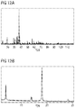
- FIG. 12A shows the X-ray powder diffractogram using copper K ⁇ 1 radiation of the fourth exemplary embodiment, which was synthesized as described in relation to FIG. 10 .
- the diffraction angles are plotted on the x axis in ° 2 ⁇ values and the intensity is plotted on the y axis.
- the fourth exemplary embodiment also has two characteristic reflections in an angular range of 11.5-12.5° 2 ⁇ and in an angular range of 18.5-19.5° 2 ⁇ .
- FIG. 12B shows a portion of the X-ray powder diffractogram from FIG. 12A .
- the two characteristic reflections in an angular range of 11.5-12.5° 2 ⁇ and in an angular range of 18.5-19.5° 2 ⁇ are clearly apparent.
- FIG. 13A shows two X-ray powder diffractograms using copper K ⁇ 1 radiation. The diffraction angles are plotted on the x axis in ° 2 ⁇ values and the intensity is plotted on the y axis.
- the X-ray powder diffractogram provided with reference sign I′′′ shows that of the fourth exemplary embodiment of the red-emitting phosphor according to the invention.
- the X-ray powder diffractogram provided with reference sign II shows that of a phosphor of formula SrLiAl 3 N 4 :Eu 2+ .
- FIGS. 1 and 4 and 7 it is here also apparent that the known phosphor does not have the characteristic reflections of the phosphor according to the invention in an angular range of 11.5-12.5° 2 ⁇ and in the range 18.5-19.5° 2 ⁇ .
- FIG. 13B shows a portion of the X-ray powder diffractogram of FIG. 13A .
- FIG. 14 shows two X-ray powder diffractograms using copper K ⁇ 1 radiation.
- the diffraction angles are plotted on the x axis in ° 2 ⁇ values and the intensity is plotted on the y axis.
- the X-ray powder diffractogram provided with reference sign I′′′ shows that the measured X-ray powder diffractogram of the fourth exemplary embodiment of the red-emitting phosphor according to the invention.
- the diffractogram provided with reference sign IV corresponds to the X-ray powder diffractogram calculated from single crystal data for the phosphor according to the invention of formula Sr 4 ⁇ x Eu x LiAl 11 N 14 .
- the reflections marked * should be assigned to a secondary phase of AlN.
- FIG. 15 shows the orthorhombic crystal structure of the phosphor Sr 4 ⁇ x Eu x LiAl 11 N 14 in a schematic diagram.
- the phosphor crystallizes orthorhombically in the space group Pnnm.
- the structure of the phosphor was determined on the basis of single crystal diffraction data.
- the structure has corner-linked and edge-linked (Al,Li)N-tetrahedra.
- Sr atoms are arranged amongst the network of tetrahedra. Descriptions in other space groups are also possible.
- the phosphor according to the invention thus has the same atomic sequence as K 2 Zn 6 O 7 .
- FIG. 16A shows crystallographic data of Sr 4 ⁇ x Eu x LiAl 11 N 14 .
- FIG. 16B shows atomic layers in the structure of Sr 4 ⁇ x Eu x LiAl 11 N 14 .
- FIG. 16C shows anisotropic displacement parameters for Sr 4 ⁇ x Eu x LiAl 11 N 14 .
- FIG. 17 shows the emission spectra of three substitution variants of the phosphor Sr 4 ⁇ x Eu x LiAl 11 N 14 .
- Substitution variants should here be understood to mean that in these phosphors the elements Sr, Eu, Li, Al and/or N in the empirical formula Sr 4 ⁇ x Eu x LiAl 11 N 14 are in part replaced by other elements.
- the wavelength in nanometers is plotted on the x axis and the emission intensity E in percent is plotted on the y axis.
- the samples in the form of individual crystals were excited with blue light of a wavelength of 460 nm.
- the phosphor which has the emission with reference sign A, shows in EDX measurements an Al:Si molar ratio of about 1:1 and has a peak wavelength of 636 nm and is thus markedly blueshifted compared with the unsubstituted phosphor Sr 4 LiAl 11 N 14 :Eu 2+ , which has a peak wavelength at 670 nm.
- FIGS. 18A and 18B show tables with possible, electroneutral compounds, which may be achieved by substitution experiments, as with general empirical formula (AX a AY b AZ c )(BV d BW e BX f BY g BZ h )(CX n CY y ):E.
- the substitutions shown are merely exemplary, other substitutions are likewise possible while preserving the crystal structure.
Landscapes
- Chemical & Material Sciences (AREA)
- Engineering & Computer Science (AREA)
- Organic Chemistry (AREA)
- Inorganic Chemistry (AREA)
- Materials Engineering (AREA)
- Ceramic Engineering (AREA)
- Manufacturing & Machinery (AREA)
- Structural Engineering (AREA)
- Microelectronics & Electronic Packaging (AREA)
- Thermal Sciences (AREA)
- Physics & Mathematics (AREA)
- Computer Hardware Design (AREA)
- Power Engineering (AREA)
- Luminescent Compositions (AREA)
- Led Device Packages (AREA)
Applications Claiming Priority (4)
| Application Number | Priority Date | Filing Date | Title |
|---|---|---|---|
| DE102015107162 | 2015-05-07 | ||
| DE102015107162.2 | 2015-05-07 | ||
| DE102015107162 | 2015-05-07 | ||
| PCT/EP2016/060208 WO2016177890A1 (de) | 2015-05-07 | 2016-05-06 | Leuchtstoff |
Publications (2)
| Publication Number | Publication Date |
|---|---|
| US20180148644A1 US20180148644A1 (en) | 2018-05-31 |
| US10752836B2 true US10752836B2 (en) | 2020-08-25 |
Family
ID=55913638
Family Applications (1)
| Application Number | Title | Priority Date | Filing Date |
|---|---|---|---|
| US15/572,449 Active 2037-04-01 US10752836B2 (en) | 2015-05-07 | 2016-05-06 | Phosphor |
Country Status (5)
| Country | Link |
|---|---|
| US (1) | US10752836B2 (zh) |
| JP (1) | JP6562366B2 (zh) |
| CN (1) | CN107592881B (zh) |
| DE (1) | DE112016002074B9 (zh) |
| WO (1) | WO2016177890A1 (zh) |
Families Citing this family (13)
| Publication number | Priority date | Publication date | Assignee | Title |
|---|---|---|---|---|
| WO2018087304A1 (de) | 2016-11-11 | 2018-05-17 | Osram Gmbh | Leuchtstoff, beleuchtungsvorrichtung und verwendung einer beleuchtungsvorrichtung |
| US10711192B2 (en) | 2016-08-12 | 2020-07-14 | Osram Oled Gmbh | Lighting device |
| DE102016121692A1 (de) * | 2016-08-12 | 2018-02-15 | Osram Gmbh | Leuchtstoff und Verfahren zur Herstellung eines Leuchtstoffs |
| WO2018029304A1 (de) * | 2016-08-12 | 2018-02-15 | Osram Gmbh | Beleuchtungsvorrichtung |
| US10644206B2 (en) | 2016-08-12 | 2020-05-05 | Osram Oled Gmbh | Lighting device |
| JP7050774B2 (ja) | 2016-11-11 | 2022-04-08 | オスラム オプト セミコンダクターズ ゲゼルシャフト ミット ベシュレンクテル ハフツング | 蛍光体、照明装置および照明装置の使用 |
| WO2019029849A1 (de) | 2016-11-11 | 2019-02-14 | Osram Opto Semiconductors Gmbh | Dimmbare lichtquelle |
| JP2018109124A (ja) * | 2017-01-05 | 2018-07-12 | 太平洋セメント株式会社 | 蛍光体の製造法 |
| DE102018205464A1 (de) | 2017-11-10 | 2019-05-16 | Osram Opto Semiconductors Gmbh | Beleuchtungsvorrichtung und verwendung einer beleuchtungsvorrichtung |
| CN109742219A (zh) * | 2018-12-06 | 2019-05-10 | 广东晶科电子股份有限公司 | 一种红色发光体、led器件及其制作方法 |
| CN110129051B (zh) * | 2019-06-02 | 2021-10-26 | 陕西师范大学 | La4Ca3Si6N14晶体及荧光粉和制备方法 |
| WO2022134045A1 (zh) * | 2020-12-25 | 2022-06-30 | 苏州君诺新材科技有限公司 | 一种氮氧化物红色荧光粉及其制备方法和器件 |
| CN113736458B (zh) * | 2021-08-18 | 2022-06-17 | 广东工业大学 | 一种近红外宽带发光材料及其制备方法和应用 |
Citations (8)
| Publication number | Priority date | Publication date | Assignee | Title |
|---|---|---|---|---|
| US20090014741A1 (en) | 2007-07-13 | 2009-01-15 | Sharp Kabushiki Kaisha | Group of phosphor particles for light-emitting device, light-emitting device and backlight for liquid crystal display |
| WO2010119375A1 (en) | 2009-04-16 | 2010-10-21 | Koninklijke Philips Electronics N.V. | Red emitting luminescent materials |
| CN102559177A (zh) | 2010-12-28 | 2012-07-11 | 北京宇极科技发展有限公司 | 一种氮氧化合物发光材料、其制备方法以及由其制成的照明光源 |
| US20130127333A1 (en) | 2010-12-28 | 2013-05-23 | Beijing Yuji Science And Technology Co. Ltd | Oxynitride luminescent material, preparation method thereof and illumination light source made from such material |
| WO2013175336A1 (en) | 2012-05-22 | 2013-11-28 | Koninklijke Philips N.V. | New phosphors, such as new narrow-band red emitting phosphors, for solid state lighting |
| WO2013180216A1 (ja) | 2012-05-31 | 2013-12-05 | 独立行政法人物質・材料研究機構 | 蛍光体、その製造方法、発光装置および画像表示装置 |
| WO2014003076A1 (ja) | 2012-06-27 | 2014-01-03 | 独立行政法人物質・材料研究機構 | 蛍光体、その製造方法、発光装置および画像表示装置 |
| WO2015044106A1 (en) | 2013-09-26 | 2015-04-02 | Koninklijke Philips N.V. | New nitridoalumosilicate phosphor for solid state lighting |
-
2016
- 2016-05-06 US US15/572,449 patent/US10752836B2/en active Active
- 2016-05-06 WO PCT/EP2016/060208 patent/WO2016177890A1/de active Application Filing
- 2016-05-06 CN CN201680026643.0A patent/CN107592881B/zh active Active
- 2016-05-06 DE DE112016002074.0T patent/DE112016002074B9/de active Active
- 2016-05-06 JP JP2017557180A patent/JP6562366B2/ja active Active
Patent Citations (16)
| Publication number | Priority date | Publication date | Assignee | Title |
|---|---|---|---|---|
| US20090014741A1 (en) | 2007-07-13 | 2009-01-15 | Sharp Kabushiki Kaisha | Group of phosphor particles for light-emitting device, light-emitting device and backlight for liquid crystal display |
| CN101412910A (zh) | 2007-07-13 | 2009-04-22 | 夏普株式会社 | 发光装置用荧光体粒子集合体、发光装置、及液晶显示用背光装置 |
| US7808012B2 (en) | 2007-07-13 | 2010-10-05 | Sharp Kabushiki Kaisha | Group of phosphor particles for light-emitting device, light-emitting device and backlight for liquid crystal display |
| WO2010119375A1 (en) | 2009-04-16 | 2010-10-21 | Koninklijke Philips Electronics N.V. | Red emitting luminescent materials |
| CN102559177A (zh) | 2010-12-28 | 2012-07-11 | 北京宇极科技发展有限公司 | 一种氮氧化合物发光材料、其制备方法以及由其制成的照明光源 |
| US20130127333A1 (en) | 2010-12-28 | 2013-05-23 | Beijing Yuji Science And Technology Co. Ltd | Oxynitride luminescent material, preparation method thereof and illumination light source made from such material |
| JP2013539490A (ja) | 2010-12-28 | 2013-10-24 | 北京宇極科技発展有限公司 | 酸窒化物発光材料及びその調製方法並びにそれによって製造された照明光源 |
| WO2013175336A1 (en) | 2012-05-22 | 2013-11-28 | Koninklijke Philips N.V. | New phosphors, such as new narrow-band red emitting phosphors, for solid state lighting |
| WO2013180216A1 (ja) | 2012-05-31 | 2013-12-05 | 独立行政法人物質・材料研究機構 | 蛍光体、その製造方法、発光装置および画像表示装置 |
| CN104024375A (zh) | 2012-05-31 | 2014-09-03 | 独立行政法人物质·材料研究机构 | 荧光体及其制备方法、发光装置及图像显示装置 |
| EP2801599A1 (en) | 2012-05-31 | 2014-11-12 | National Institute for Materials Science | Phosphor, method for manufacturing same, light emitting device, and image display device |
| US9458379B2 (en) | 2012-05-31 | 2016-10-04 | National Institute For Materials Science | Phosphor, method for manufacturing same, light emitting device, and image display device |
| WO2014003076A1 (ja) | 2012-06-27 | 2014-01-03 | 独立行政法人物質・材料研究機構 | 蛍光体、その製造方法、発光装置および画像表示装置 |
| CN104080886A (zh) | 2012-06-27 | 2014-10-01 | 独立行政法人物质·材料研究机构 | 荧光体及其制备方法、发光装置及图像显示装置 |
| US9534171B2 (en) | 2012-06-27 | 2017-01-03 | National Institute For Materials Science | Phosphor, method for producing same, light emitting device, and image display device |
| WO2015044106A1 (en) | 2013-09-26 | 2015-04-02 | Koninklijke Philips N.V. | New nitridoalumosilicate phosphor for solid state lighting |
Non-Patent Citations (4)
| Title |
|---|
| Detail information for K2Zn6O7, The Materials Project; materialsproject.org, no date. * |
| Pust, P. et al., "Narrow-band Red-Emitting Sr[LiAl3N4]: Eu2+ as a Next-Generation LED-Phosphor Material," Natures Materials, Jun. 22, 2014, 6 pages. |
| Zhang, Z. et al., "Preparation, Electronic Structure and Photoluminescence Properties of RE )RE=Ce, Yb)-Activated SrAlSi4N7 Phosphors," Journals of Materials Chemistry C, XP-002758971, RSC Publishing, 2013, 10 pages. |
| ZHIJUN ZHANG, OTMAR M. TEN KATE, ANNEKE C. A. DELSING, ZHENYONG MAN , RONGJUN XIE, YUFANG SHEN , MARJO J. H. STEVENS, PETER H. L.: "Preparation, electronic structure and photoluminescence properties of RE (RE= Ce, Yb)-activated SrAlSi4N7 phosphors", JOURNAL OF MATERIALS CHEMISTRY C, ROYAL SOCIETY OF CHEMISTRY, GB, vol. 1, no. 47, 21 December 2013 (2013-12-21), GB, pages 7856 - 7865, XP002758971, ISSN: 2050-7526, DOI: 10.1039/C3TC31628A |
Also Published As
| Publication number | Publication date |
|---|---|
| DE112016002074B4 (de) | 2022-11-03 |
| DE112016002074B9 (de) | 2023-01-12 |
| CN107592881A (zh) | 2018-01-16 |
| JP2018517806A (ja) | 2018-07-05 |
| JP6562366B2 (ja) | 2019-08-21 |
| US20180148644A1 (en) | 2018-05-31 |
| CN107592881B (zh) | 2021-07-02 |
| WO2016177890A1 (de) | 2016-11-10 |
| DE112016002074A5 (de) | 2018-02-22 |
Similar Documents
| Publication | Publication Date | Title |
|---|---|---|
| US10752836B2 (en) | Phosphor | |
| JP5188687B2 (ja) | 蛍光体及びその製造法並びに発光装置 | |
| JP5190475B2 (ja) | 蛍光体およびそれを用いた発光装置 | |
| JP2006213910A (ja) | 酸窒化物蛍光体及び発光装置 | |
| TW201900850A (zh) | 螢光體及其用途 | |
| JP6475257B2 (ja) | 固体照明用のスーパーテトラヘドロン蛍光体 | |
| JP6985704B2 (ja) | 蛍光体、発光装置、照明装置及び画像表示装置 | |
| US9890328B2 (en) | Phosphor compositions and lighting apparatus thereof | |
| Ji et al. | Luminescent thermal stability and electronic structure of narrow-band green-emitting Sr-Sialon: Eu2+ phosphors for LED/LCD backlights | |
| Wang et al. | Synthesis and photoluminescence properties of a phase pure green-emitting Eu doped JEM sialon (LaSi 6− z Al 1+ z N 10− z O z, z∼ 1) phosphor with a large red-shift of emission and unusual thermal quenching behavior | |
| US11441070B2 (en) | Red emitting luminescent material | |
| Xiaoming et al. | Luminescence properties of nitride red phosphor for LED | |
| Tian et al. | Excellent human eye sensitivity matching, high luminous efficacy, high quantum yield and thermal stability of narrow-band red-emitting SrLiAl3N4: Eu2+ phosphor | |
| US10539275B2 (en) | LED phosphor comprising bow-tie shaped A2N6 building blocks | |
| Yang et al. | Synthesis, structure and photoluminescence properties of fine yellow-orange Ca-α-SiAlON: Eu2+ phosphors | |
| KR101243774B1 (ko) | 산질화물 형광체 | |
| KR101525317B1 (ko) | 형광체 및 이를 포함하는 발광장치 | |
| CN111247228B (zh) | 发光材料和转换型led | |
| Yamamoto et al. | Phosphors for white LEDs | |
| US20210246369A1 (en) | Red luminescent material and conversion led | |
| JP6776556B2 (ja) | 蛍光体、発光装置、画像表示装置及び照明装置 | |
| EP3313959B1 (en) | Phosphor compositions and lighting apparatus thereof | |
| Li et al. | Tunable emission of Ce3+ in (K, Rb) 3GdSi2O7 phosphors toward broadband cyan luminescence | |
| Gao et al. | Enhanced luminescence properties of Sr3− xEuxAlO4− yNyF phosphors | |
| KR20160112163A (ko) | 산 질화물 형광체 및 이를 이용한 발광 소자 패키지 |
Legal Events
| Date | Code | Title | Description |
|---|---|---|---|
| FEPP | Fee payment procedure |
Free format text: ENTITY STATUS SET TO UNDISCOUNTED (ORIGINAL EVENT CODE: BIG.); ENTITY STATUS OF PATENT OWNER: LARGE ENTITY |
|
| AS | Assignment |
Owner name: OSRAM OPTO SEMICONDUCTORS GMBH, GERMANY Free format text: ASSIGNMENT OF ASSIGNORS INTEREST;ASSIGNORS:SEIBALD, MARKUS;FIEDLER, TIM;BAUMANN, DOMINIK;AND OTHERS;SIGNING DATES FROM 20180228 TO 20180305;REEL/FRAME:045375/0885 |
|
| STPP | Information on status: patent application and granting procedure in general |
Free format text: DOCKETED NEW CASE - READY FOR EXAMINATION |
|
| AS | Assignment |
Owner name: OSRAM OLED GMBH, GERMANY Free format text: ASSIGNMENT OF ASSIGNORS INTEREST;ASSIGNOR:OSRAM OPTO SEMICONDUCTORS GMBH;REEL/FRAME:051464/0504 Effective date: 20191218 |
|
| STPP | Information on status: patent application and granting procedure in general |
Free format text: NON FINAL ACTION MAILED |
|
| STPP | Information on status: patent application and granting procedure in general |
Free format text: NOTICE OF ALLOWANCE MAILED -- APPLICATION RECEIVED IN OFFICE OF PUBLICATIONS |
|
| STPP | Information on status: patent application and granting procedure in general |
Free format text: PUBLICATIONS -- ISSUE FEE PAYMENT RECEIVED |
|
| STCF | Information on status: patent grant |
Free format text: PATENTED CASE |
|
| MAFP | Maintenance fee payment |
Free format text: PAYMENT OF MAINTENANCE FEE, 4TH YEAR, LARGE ENTITY (ORIGINAL EVENT CODE: M1551); ENTITY STATUS OF PATENT OWNER: LARGE ENTITY Year of fee payment: 4 |