US10606264B2 - Control method and control device of automatic driving vehicle - Google Patents
Control method and control device of automatic driving vehicle Download PDFInfo
- Publication number
- US10606264B2 US10606264B2 US16/323,744 US201616323744A US10606264B2 US 10606264 B2 US10606264 B2 US 10606264B2 US 201616323744 A US201616323744 A US 201616323744A US 10606264 B2 US10606264 B2 US 10606264B2
- Authority
- US
- United States
- Prior art keywords
- vehicle
- automatic driving
- manual
- driving
- driving characteristics
- Prior art date
- Legal status (The legal status is an assumption and is not a legal conclusion. Google has not performed a legal analysis and makes no representation as to the accuracy of the status listed.)
- Active
Links
- 238000000034 method Methods 0.000 title claims abstract description 49
- 230000007704 transition Effects 0.000 claims description 30
- 230000007423 decrease Effects 0.000 claims description 19
- 230000009467 reduction Effects 0.000 claims description 7
- 230000008859 change Effects 0.000 description 42
- 238000001514 detection method Methods 0.000 description 40
- 230000001133 acceleration Effects 0.000 description 10
- 238000010801 machine learning Methods 0.000 description 10
- 230000036461 convulsion Effects 0.000 description 9
- 230000006870 function Effects 0.000 description 5
- 230000009471 action Effects 0.000 description 4
- 238000010586 diagram Methods 0.000 description 4
- 230000002411 adverse Effects 0.000 description 2
- 238000004891 communication Methods 0.000 description 2
- 230000000694 effects Effects 0.000 description 2
- 238000007781 pre-processing Methods 0.000 description 2
- 238000004364 calculation method Methods 0.000 description 1
- 238000007477 logistic regression Methods 0.000 description 1
- 239000000463 material Substances 0.000 description 1
- 238000012706 support-vector machine Methods 0.000 description 1
Images


Classifications
-
- G—PHYSICS
- G05—CONTROLLING; REGULATING
- G05D—SYSTEMS FOR CONTROLLING OR REGULATING NON-ELECTRIC VARIABLES
- G05D1/00—Control of position, course, altitude or attitude of land, water, air or space vehicles, e.g. using automatic pilots
- G05D1/0055—Control of position, course, altitude or attitude of land, water, air or space vehicles, e.g. using automatic pilots with safety arrangements
- G05D1/0061—Control of position, course, altitude or attitude of land, water, air or space vehicles, e.g. using automatic pilots with safety arrangements for transition from automatic pilot to manual pilot and vice versa
-
- B—PERFORMING OPERATIONS; TRANSPORTING
- B60—VEHICLES IN GENERAL
- B60W—CONJOINT CONTROL OF VEHICLE SUB-UNITS OF DIFFERENT TYPE OR DIFFERENT FUNCTION; CONTROL SYSTEMS SPECIALLY ADAPTED FOR HYBRID VEHICLES; ROAD VEHICLE DRIVE CONTROL SYSTEMS FOR PURPOSES NOT RELATED TO THE CONTROL OF A PARTICULAR SUB-UNIT
- B60W10/00—Conjoint control of vehicle sub-units of different type or different function
- B60W10/04—Conjoint control of vehicle sub-units of different type or different function including control of propulsion units
-
- B—PERFORMING OPERATIONS; TRANSPORTING
- B60—VEHICLES IN GENERAL
- B60W—CONJOINT CONTROL OF VEHICLE SUB-UNITS OF DIFFERENT TYPE OR DIFFERENT FUNCTION; CONTROL SYSTEMS SPECIALLY ADAPTED FOR HYBRID VEHICLES; ROAD VEHICLE DRIVE CONTROL SYSTEMS FOR PURPOSES NOT RELATED TO THE CONTROL OF A PARTICULAR SUB-UNIT
- B60W10/00—Conjoint control of vehicle sub-units of different type or different function
- B60W10/18—Conjoint control of vehicle sub-units of different type or different function including control of braking systems
- B60W10/184—Conjoint control of vehicle sub-units of different type or different function including control of braking systems with wheel brakes
-
- B—PERFORMING OPERATIONS; TRANSPORTING
- B60—VEHICLES IN GENERAL
- B60W—CONJOINT CONTROL OF VEHICLE SUB-UNITS OF DIFFERENT TYPE OR DIFFERENT FUNCTION; CONTROL SYSTEMS SPECIALLY ADAPTED FOR HYBRID VEHICLES; ROAD VEHICLE DRIVE CONTROL SYSTEMS FOR PURPOSES NOT RELATED TO THE CONTROL OF A PARTICULAR SUB-UNIT
- B60W30/00—Purposes of road vehicle drive control systems not related to the control of a particular sub-unit, e.g. of systems using conjoint control of vehicle sub-units
- B60W30/14—Adaptive cruise control
- B60W30/143—Speed control
-
- B—PERFORMING OPERATIONS; TRANSPORTING
- B60—VEHICLES IN GENERAL
- B60W—CONJOINT CONTROL OF VEHICLE SUB-UNITS OF DIFFERENT TYPE OR DIFFERENT FUNCTION; CONTROL SYSTEMS SPECIALLY ADAPTED FOR HYBRID VEHICLES; ROAD VEHICLE DRIVE CONTROL SYSTEMS FOR PURPOSES NOT RELATED TO THE CONTROL OF A PARTICULAR SUB-UNIT
- B60W30/00—Purposes of road vehicle drive control systems not related to the control of a particular sub-unit, e.g. of systems using conjoint control of vehicle sub-units
- B60W30/14—Adaptive cruise control
- B60W30/16—Control of distance between vehicles, e.g. keeping a distance to preceding vehicle
- B60W30/17—Control of distance between vehicles, e.g. keeping a distance to preceding vehicle with provision for special action when the preceding vehicle comes to a halt, e.g. stop and go
-
- B—PERFORMING OPERATIONS; TRANSPORTING
- B60—VEHICLES IN GENERAL
- B60W—CONJOINT CONTROL OF VEHICLE SUB-UNITS OF DIFFERENT TYPE OR DIFFERENT FUNCTION; CONTROL SYSTEMS SPECIALLY ADAPTED FOR HYBRID VEHICLES; ROAD VEHICLE DRIVE CONTROL SYSTEMS FOR PURPOSES NOT RELATED TO THE CONTROL OF A PARTICULAR SUB-UNIT
- B60W30/00—Purposes of road vehicle drive control systems not related to the control of a particular sub-unit, e.g. of systems using conjoint control of vehicle sub-units
- B60W30/18—Propelling the vehicle
- B60W30/18009—Propelling the vehicle related to particular drive situations
- B60W30/181—Preparing for stopping
-
- B—PERFORMING OPERATIONS; TRANSPORTING
- B60—VEHICLES IN GENERAL
- B60W—CONJOINT CONTROL OF VEHICLE SUB-UNITS OF DIFFERENT TYPE OR DIFFERENT FUNCTION; CONTROL SYSTEMS SPECIALLY ADAPTED FOR HYBRID VEHICLES; ROAD VEHICLE DRIVE CONTROL SYSTEMS FOR PURPOSES NOT RELATED TO THE CONTROL OF A PARTICULAR SUB-UNIT
- B60W30/00—Purposes of road vehicle drive control systems not related to the control of a particular sub-unit, e.g. of systems using conjoint control of vehicle sub-units
- B60W30/18—Propelling the vehicle
- B60W30/18009—Propelling the vehicle related to particular drive situations
- B60W30/18109—Braking
-
- B—PERFORMING OPERATIONS; TRANSPORTING
- B60—VEHICLES IN GENERAL
- B60W—CONJOINT CONTROL OF VEHICLE SUB-UNITS OF DIFFERENT TYPE OR DIFFERENT FUNCTION; CONTROL SYSTEMS SPECIALLY ADAPTED FOR HYBRID VEHICLES; ROAD VEHICLE DRIVE CONTROL SYSTEMS FOR PURPOSES NOT RELATED TO THE CONTROL OF A PARTICULAR SUB-UNIT
- B60W30/00—Purposes of road vehicle drive control systems not related to the control of a particular sub-unit, e.g. of systems using conjoint control of vehicle sub-units
- B60W30/18—Propelling the vehicle
- B60W30/18009—Propelling the vehicle related to particular drive situations
- B60W30/18145—Cornering
-
- B—PERFORMING OPERATIONS; TRANSPORTING
- B60—VEHICLES IN GENERAL
- B60W—CONJOINT CONTROL OF VEHICLE SUB-UNITS OF DIFFERENT TYPE OR DIFFERENT FUNCTION; CONTROL SYSTEMS SPECIALLY ADAPTED FOR HYBRID VEHICLES; ROAD VEHICLE DRIVE CONTROL SYSTEMS FOR PURPOSES NOT RELATED TO THE CONTROL OF A PARTICULAR SUB-UNIT
- B60W30/00—Purposes of road vehicle drive control systems not related to the control of a particular sub-unit, e.g. of systems using conjoint control of vehicle sub-units
- B60W30/18—Propelling the vehicle
- B60W30/182—Selecting between different operative modes, e.g. comfort and performance modes
-
- B—PERFORMING OPERATIONS; TRANSPORTING
- B60—VEHICLES IN GENERAL
- B60W—CONJOINT CONTROL OF VEHICLE SUB-UNITS OF DIFFERENT TYPE OR DIFFERENT FUNCTION; CONTROL SYSTEMS SPECIALLY ADAPTED FOR HYBRID VEHICLES; ROAD VEHICLE DRIVE CONTROL SYSTEMS FOR PURPOSES NOT RELATED TO THE CONTROL OF A PARTICULAR SUB-UNIT
- B60W40/00—Estimation or calculation of non-directly measurable driving parameters for road vehicle drive control systems not related to the control of a particular sub unit, e.g. by using mathematical models
- B60W40/02—Estimation or calculation of non-directly measurable driving parameters for road vehicle drive control systems not related to the control of a particular sub unit, e.g. by using mathematical models related to ambient conditions
- B60W40/06—Road conditions
-
- B—PERFORMING OPERATIONS; TRANSPORTING
- B60—VEHICLES IN GENERAL
- B60W—CONJOINT CONTROL OF VEHICLE SUB-UNITS OF DIFFERENT TYPE OR DIFFERENT FUNCTION; CONTROL SYSTEMS SPECIALLY ADAPTED FOR HYBRID VEHICLES; ROAD VEHICLE DRIVE CONTROL SYSTEMS FOR PURPOSES NOT RELATED TO THE CONTROL OF A PARTICULAR SUB-UNIT
- B60W40/00—Estimation or calculation of non-directly measurable driving parameters for road vehicle drive control systems not related to the control of a particular sub unit, e.g. by using mathematical models
- B60W40/08—Estimation or calculation of non-directly measurable driving parameters for road vehicle drive control systems not related to the control of a particular sub unit, e.g. by using mathematical models related to drivers or passengers
-
- B—PERFORMING OPERATIONS; TRANSPORTING
- B60—VEHICLES IN GENERAL
- B60W—CONJOINT CONTROL OF VEHICLE SUB-UNITS OF DIFFERENT TYPE OR DIFFERENT FUNCTION; CONTROL SYSTEMS SPECIALLY ADAPTED FOR HYBRID VEHICLES; ROAD VEHICLE DRIVE CONTROL SYSTEMS FOR PURPOSES NOT RELATED TO THE CONTROL OF A PARTICULAR SUB-UNIT
- B60W40/00—Estimation or calculation of non-directly measurable driving parameters for road vehicle drive control systems not related to the control of a particular sub unit, e.g. by using mathematical models
- B60W40/10—Estimation or calculation of non-directly measurable driving parameters for road vehicle drive control systems not related to the control of a particular sub unit, e.g. by using mathematical models related to vehicle motion
- B60W40/105—Speed
-
- B—PERFORMING OPERATIONS; TRANSPORTING
- B60—VEHICLES IN GENERAL
- B60W—CONJOINT CONTROL OF VEHICLE SUB-UNITS OF DIFFERENT TYPE OR DIFFERENT FUNCTION; CONTROL SYSTEMS SPECIALLY ADAPTED FOR HYBRID VEHICLES; ROAD VEHICLE DRIVE CONTROL SYSTEMS FOR PURPOSES NOT RELATED TO THE CONTROL OF A PARTICULAR SUB-UNIT
- B60W50/00—Details of control systems for road vehicle drive control not related to the control of a particular sub-unit, e.g. process diagnostic or vehicle driver interfaces
- B60W50/08—Interaction between the driver and the control system
- B60W50/082—Selecting or switching between different modes of propelling
-
- B—PERFORMING OPERATIONS; TRANSPORTING
- B60—VEHICLES IN GENERAL
- B60W—CONJOINT CONTROL OF VEHICLE SUB-UNITS OF DIFFERENT TYPE OR DIFFERENT FUNCTION; CONTROL SYSTEMS SPECIALLY ADAPTED FOR HYBRID VEHICLES; ROAD VEHICLE DRIVE CONTROL SYSTEMS FOR PURPOSES NOT RELATED TO THE CONTROL OF A PARTICULAR SUB-UNIT
- B60W60/00—Drive control systems specially adapted for autonomous road vehicles
- B60W60/001—Planning or execution of driving tasks
- B60W60/0013—Planning or execution of driving tasks specially adapted for occupant comfort
-
- B—PERFORMING OPERATIONS; TRANSPORTING
- B60—VEHICLES IN GENERAL
- B60W—CONJOINT CONTROL OF VEHICLE SUB-UNITS OF DIFFERENT TYPE OR DIFFERENT FUNCTION; CONTROL SYSTEMS SPECIALLY ADAPTED FOR HYBRID VEHICLES; ROAD VEHICLE DRIVE CONTROL SYSTEMS FOR PURPOSES NOT RELATED TO THE CONTROL OF A PARTICULAR SUB-UNIT
- B60W60/00—Drive control systems specially adapted for autonomous road vehicles
- B60W60/005—Handover processes
- B60W60/0051—Handover processes from occupants to vehicle
-
- G—PHYSICS
- G05—CONTROLLING; REGULATING
- G05D—SYSTEMS FOR CONTROLLING OR REGULATING NON-ELECTRIC VARIABLES
- G05D1/00—Control of position, course, altitude or attitude of land, water, air or space vehicles, e.g. using automatic pilots
- G05D1/0088—Control of position, course, altitude or attitude of land, water, air or space vehicles, e.g. using automatic pilots characterized by the autonomous decision making process, e.g. artificial intelligence, predefined behaviours
-
- B—PERFORMING OPERATIONS; TRANSPORTING
- B60—VEHICLES IN GENERAL
- B60K—ARRANGEMENT OR MOUNTING OF PROPULSION UNITS OR OF TRANSMISSIONS IN VEHICLES; ARRANGEMENT OR MOUNTING OF PLURAL DIVERSE PRIME-MOVERS IN VEHICLES; AUXILIARY DRIVES FOR VEHICLES; INSTRUMENTATION OR DASHBOARDS FOR VEHICLES; ARRANGEMENTS IN CONNECTION WITH COOLING, AIR INTAKE, GAS EXHAUST OR FUEL SUPPLY OF PROPULSION UNITS IN VEHICLES
- B60K2310/00—Arrangements, adaptations or methods for cruise controls
- B60K2310/24—Speed setting methods
- B60K2310/242—Speed setting methods setting initial target speed, e.g. initial algorithms
-
- B—PERFORMING OPERATIONS; TRANSPORTING
- B60—VEHICLES IN GENERAL
- B60K—ARRANGEMENT OR MOUNTING OF PROPULSION UNITS OR OF TRANSMISSIONS IN VEHICLES; ARRANGEMENT OR MOUNTING OF PLURAL DIVERSE PRIME-MOVERS IN VEHICLES; AUXILIARY DRIVES FOR VEHICLES; INSTRUMENTATION OR DASHBOARDS FOR VEHICLES; ARRANGEMENTS IN CONNECTION WITH COOLING, AIR INTAKE, GAS EXHAUST OR FUEL SUPPLY OF PROPULSION UNITS IN VEHICLES
- B60K2310/00—Arrangements, adaptations or methods for cruise controls
- B60K2310/24—Speed setting methods
- B60K2310/244—Speed setting methods changing target speed or setting a new target speed, e.g. changing algorithms
-
- B—PERFORMING OPERATIONS; TRANSPORTING
- B60—VEHICLES IN GENERAL
- B60K—ARRANGEMENT OR MOUNTING OF PROPULSION UNITS OR OF TRANSMISSIONS IN VEHICLES; ARRANGEMENT OR MOUNTING OF PLURAL DIVERSE PRIME-MOVERS IN VEHICLES; AUXILIARY DRIVES FOR VEHICLES; INSTRUMENTATION OR DASHBOARDS FOR VEHICLES; ARRANGEMENTS IN CONNECTION WITH COOLING, AIR INTAKE, GAS EXHAUST OR FUEL SUPPLY OF PROPULSION UNITS IN VEHICLES
- B60K2310/00—Arrangements, adaptations or methods for cruise controls
- B60K2310/26—Distance setting methods, e.g. determining target distance to target vehicle
- B60K2310/262—Distance setting methods, e.g. determining target distance to target vehicle setting initial distance to preceding vehicle, e.g. initial algorithms
-
- B—PERFORMING OPERATIONS; TRANSPORTING
- B60—VEHICLES IN GENERAL
- B60K—ARRANGEMENT OR MOUNTING OF PROPULSION UNITS OR OF TRANSMISSIONS IN VEHICLES; ARRANGEMENT OR MOUNTING OF PLURAL DIVERSE PRIME-MOVERS IN VEHICLES; AUXILIARY DRIVES FOR VEHICLES; INSTRUMENTATION OR DASHBOARDS FOR VEHICLES; ARRANGEMENTS IN CONNECTION WITH COOLING, AIR INTAKE, GAS EXHAUST OR FUEL SUPPLY OF PROPULSION UNITS IN VEHICLES
- B60K2310/00—Arrangements, adaptations or methods for cruise controls
- B60K2310/26—Distance setting methods, e.g. determining target distance to target vehicle
- B60K2310/264—Distance setting methods, e.g. determining target distance to target vehicle changing distance, e.g. reducing the distance for overtaking
-
- B—PERFORMING OPERATIONS; TRANSPORTING
- B60—VEHICLES IN GENERAL
- B60W—CONJOINT CONTROL OF VEHICLE SUB-UNITS OF DIFFERENT TYPE OR DIFFERENT FUNCTION; CONTROL SYSTEMS SPECIALLY ADAPTED FOR HYBRID VEHICLES; ROAD VEHICLE DRIVE CONTROL SYSTEMS FOR PURPOSES NOT RELATED TO THE CONTROL OF A PARTICULAR SUB-UNIT
- B60W40/00—Estimation or calculation of non-directly measurable driving parameters for road vehicle drive control systems not related to the control of a particular sub unit, e.g. by using mathematical models
- B60W40/08—Estimation or calculation of non-directly measurable driving parameters for road vehicle drive control systems not related to the control of a particular sub unit, e.g. by using mathematical models related to drivers or passengers
- B60W2040/0872—Driver physiology
-
- B—PERFORMING OPERATIONS; TRANSPORTING
- B60—VEHICLES IN GENERAL
- B60W—CONJOINT CONTROL OF VEHICLE SUB-UNITS OF DIFFERENT TYPE OR DIFFERENT FUNCTION; CONTROL SYSTEMS SPECIALLY ADAPTED FOR HYBRID VEHICLES; ROAD VEHICLE DRIVE CONTROL SYSTEMS FOR PURPOSES NOT RELATED TO THE CONTROL OF A PARTICULAR SUB-UNIT
- B60W50/00—Details of control systems for road vehicle drive control not related to the control of a particular sub-unit, e.g. process diagnostic or vehicle driver interfaces
- B60W2050/0062—Adapting control system settings
- B60W2050/0075—Automatic parameter input, automatic initialising or calibrating means
- B60W2050/0083—Setting, resetting, calibration
- B60W2050/0088—Adaptive recalibration
-
- B—PERFORMING OPERATIONS; TRANSPORTING
- B60—VEHICLES IN GENERAL
- B60W—CONJOINT CONTROL OF VEHICLE SUB-UNITS OF DIFFERENT TYPE OR DIFFERENT FUNCTION; CONTROL SYSTEMS SPECIALLY ADAPTED FOR HYBRID VEHICLES; ROAD VEHICLE DRIVE CONTROL SYSTEMS FOR PURPOSES NOT RELATED TO THE CONTROL OF A PARTICULAR SUB-UNIT
- B60W2420/00—Indexing codes relating to the type of sensors based on the principle of their operation
- B60W2420/40—Photo, light or radio wave sensitive means, e.g. infrared sensors
- B60W2420/403—Image sensing, e.g. optical camera
-
- B—PERFORMING OPERATIONS; TRANSPORTING
- B60—VEHICLES IN GENERAL
- B60W—CONJOINT CONTROL OF VEHICLE SUB-UNITS OF DIFFERENT TYPE OR DIFFERENT FUNCTION; CONTROL SYSTEMS SPECIALLY ADAPTED FOR HYBRID VEHICLES; ROAD VEHICLE DRIVE CONTROL SYSTEMS FOR PURPOSES NOT RELATED TO THE CONTROL OF A PARTICULAR SUB-UNIT
- B60W2420/00—Indexing codes relating to the type of sensors based on the principle of their operation
- B60W2420/40—Photo, light or radio wave sensitive means, e.g. infrared sensors
- B60W2420/408—Radar; Laser, e.g. lidar
-
- B—PERFORMING OPERATIONS; TRANSPORTING
- B60—VEHICLES IN GENERAL
- B60W—CONJOINT CONTROL OF VEHICLE SUB-UNITS OF DIFFERENT TYPE OR DIFFERENT FUNCTION; CONTROL SYSTEMS SPECIALLY ADAPTED FOR HYBRID VEHICLES; ROAD VEHICLE DRIVE CONTROL SYSTEMS FOR PURPOSES NOT RELATED TO THE CONTROL OF A PARTICULAR SUB-UNIT
- B60W2520/00—Input parameters relating to overall vehicle dynamics
- B60W2520/10—Longitudinal speed
- B60W2520/105—Longitudinal acceleration
-
- B—PERFORMING OPERATIONS; TRANSPORTING
- B60—VEHICLES IN GENERAL
- B60W—CONJOINT CONTROL OF VEHICLE SUB-UNITS OF DIFFERENT TYPE OR DIFFERENT FUNCTION; CONTROL SYSTEMS SPECIALLY ADAPTED FOR HYBRID VEHICLES; ROAD VEHICLE DRIVE CONTROL SYSTEMS FOR PURPOSES NOT RELATED TO THE CONTROL OF A PARTICULAR SUB-UNIT
- B60W2540/00—Input parameters relating to occupants
- B60W2540/18—Steering angle
-
- B60W2550/141—
-
- B60W2550/22—
-
- B60W2550/402—
-
- B—PERFORMING OPERATIONS; TRANSPORTING
- B60—VEHICLES IN GENERAL
- B60W—CONJOINT CONTROL OF VEHICLE SUB-UNITS OF DIFFERENT TYPE OR DIFFERENT FUNCTION; CONTROL SYSTEMS SPECIALLY ADAPTED FOR HYBRID VEHICLES; ROAD VEHICLE DRIVE CONTROL SYSTEMS FOR PURPOSES NOT RELATED TO THE CONTROL OF A PARTICULAR SUB-UNIT
- B60W2552/00—Input parameters relating to infrastructure
- B60W2552/05—Type of road, e.g. motorways, local streets, paved or unpaved roads
-
- B—PERFORMING OPERATIONS; TRANSPORTING
- B60—VEHICLES IN GENERAL
- B60W—CONJOINT CONTROL OF VEHICLE SUB-UNITS OF DIFFERENT TYPE OR DIFFERENT FUNCTION; CONTROL SYSTEMS SPECIALLY ADAPTED FOR HYBRID VEHICLES; ROAD VEHICLE DRIVE CONTROL SYSTEMS FOR PURPOSES NOT RELATED TO THE CONTROL OF A PARTICULAR SUB-UNIT
- B60W2552/00—Input parameters relating to infrastructure
- B60W2552/53—Road markings, e.g. lane marker or crosswalk
-
- B—PERFORMING OPERATIONS; TRANSPORTING
- B60—VEHICLES IN GENERAL
- B60W—CONJOINT CONTROL OF VEHICLE SUB-UNITS OF DIFFERENT TYPE OR DIFFERENT FUNCTION; CONTROL SYSTEMS SPECIALLY ADAPTED FOR HYBRID VEHICLES; ROAD VEHICLE DRIVE CONTROL SYSTEMS FOR PURPOSES NOT RELATED TO THE CONTROL OF A PARTICULAR SUB-UNIT
- B60W2554/00—Input parameters relating to objects
- B60W2554/40—Dynamic objects, e.g. animals, windblown objects
- B60W2554/402—Type
- B60W2554/4026—Cycles
-
- B—PERFORMING OPERATIONS; TRANSPORTING
- B60—VEHICLES IN GENERAL
- B60W—CONJOINT CONTROL OF VEHICLE SUB-UNITS OF DIFFERENT TYPE OR DIFFERENT FUNCTION; CONTROL SYSTEMS SPECIALLY ADAPTED FOR HYBRID VEHICLES; ROAD VEHICLE DRIVE CONTROL SYSTEMS FOR PURPOSES NOT RELATED TO THE CONTROL OF A PARTICULAR SUB-UNIT
- B60W2554/00—Input parameters relating to objects
- B60W2554/40—Dynamic objects, e.g. animals, windblown objects
- B60W2554/402—Type
- B60W2554/4029—Pedestrians
-
- B—PERFORMING OPERATIONS; TRANSPORTING
- B60—VEHICLES IN GENERAL
- B60W—CONJOINT CONTROL OF VEHICLE SUB-UNITS OF DIFFERENT TYPE OR DIFFERENT FUNCTION; CONTROL SYSTEMS SPECIALLY ADAPTED FOR HYBRID VEHICLES; ROAD VEHICLE DRIVE CONTROL SYSTEMS FOR PURPOSES NOT RELATED TO THE CONTROL OF A PARTICULAR SUB-UNIT
- B60W2554/00—Input parameters relating to objects
- B60W2554/80—Spatial relation or speed relative to objects
- B60W2554/801—Lateral distance
-
- B—PERFORMING OPERATIONS; TRANSPORTING
- B60—VEHICLES IN GENERAL
- B60W—CONJOINT CONTROL OF VEHICLE SUB-UNITS OF DIFFERENT TYPE OR DIFFERENT FUNCTION; CONTROL SYSTEMS SPECIALLY ADAPTED FOR HYBRID VEHICLES; ROAD VEHICLE DRIVE CONTROL SYSTEMS FOR PURPOSES NOT RELATED TO THE CONTROL OF A PARTICULAR SUB-UNIT
- B60W2554/00—Input parameters relating to objects
- B60W2554/80—Spatial relation or speed relative to objects
- B60W2554/802—Longitudinal distance
-
- B—PERFORMING OPERATIONS; TRANSPORTING
- B60—VEHICLES IN GENERAL
- B60W—CONJOINT CONTROL OF VEHICLE SUB-UNITS OF DIFFERENT TYPE OR DIFFERENT FUNCTION; CONTROL SYSTEMS SPECIALLY ADAPTED FOR HYBRID VEHICLES; ROAD VEHICLE DRIVE CONTROL SYSTEMS FOR PURPOSES NOT RELATED TO THE CONTROL OF A PARTICULAR SUB-UNIT
- B60W2555/00—Input parameters relating to exterior conditions, not covered by groups B60W2552/00, B60W2554/00
- B60W2555/60—Traffic rules, e.g. speed limits or right of way
-
- B—PERFORMING OPERATIONS; TRANSPORTING
- B60—VEHICLES IN GENERAL
- B60W—CONJOINT CONTROL OF VEHICLE SUB-UNITS OF DIFFERENT TYPE OR DIFFERENT FUNCTION; CONTROL SYSTEMS SPECIALLY ADAPTED FOR HYBRID VEHICLES; ROAD VEHICLE DRIVE CONTROL SYSTEMS FOR PURPOSES NOT RELATED TO THE CONTROL OF A PARTICULAR SUB-UNIT
- B60W2556/00—Input parameters relating to data
- B60W2556/45—External transmission of data to or from the vehicle
- B60W2556/50—External transmission of data to or from the vehicle of positioning data, e.g. GPS [Global Positioning System] data
-
- B—PERFORMING OPERATIONS; TRANSPORTING
- B60—VEHICLES IN GENERAL
- B60W—CONJOINT CONTROL OF VEHICLE SUB-UNITS OF DIFFERENT TYPE OR DIFFERENT FUNCTION; CONTROL SYSTEMS SPECIALLY ADAPTED FOR HYBRID VEHICLES; ROAD VEHICLE DRIVE CONTROL SYSTEMS FOR PURPOSES NOT RELATED TO THE CONTROL OF A PARTICULAR SUB-UNIT
- B60W2720/00—Output or target parameters relating to overall vehicle dynamics
- B60W2720/10—Longitudinal speed
- B60W2720/106—Longitudinal acceleration
-
- B60W2750/308—
-
- B—PERFORMING OPERATIONS; TRANSPORTING
- B60—VEHICLES IN GENERAL
- B60W—CONJOINT CONTROL OF VEHICLE SUB-UNITS OF DIFFERENT TYPE OR DIFFERENT FUNCTION; CONTROL SYSTEMS SPECIALLY ADAPTED FOR HYBRID VEHICLES; ROAD VEHICLE DRIVE CONTROL SYSTEMS FOR PURPOSES NOT RELATED TO THE CONTROL OF A PARTICULAR SUB-UNIT
- B60W2754/00—Output or target parameters relating to objects
- B60W2754/10—Spatial relation or speed relative to objects
- B60W2754/30—Longitudinal distance
-
- B—PERFORMING OPERATIONS; TRANSPORTING
- B60—VEHICLES IN GENERAL
- B60W—CONJOINT CONTROL OF VEHICLE SUB-UNITS OF DIFFERENT TYPE OR DIFFERENT FUNCTION; CONTROL SYSTEMS SPECIALLY ADAPTED FOR HYBRID VEHICLES; ROAD VEHICLE DRIVE CONTROL SYSTEMS FOR PURPOSES NOT RELATED TO THE CONTROL OF A PARTICULAR SUB-UNIT
- B60W2754/00—Output or target parameters relating to objects
- B60W2754/10—Spatial relation or speed relative to objects
- B60W2754/50—Relative longitudinal speed
-
- G05D2201/0213—
Definitions
- the present invention has been made to solve such a conventional problem and an object thereof is to provide a control method and a control device of an automatic driving vehicle which can suppress uneasiness of an occupant in switching from manual driving to automatic driving.
- the automatic driving when switching from manual driving to automatic driving is performed, the automatic driving is performed with manual driving characteristics maintained, the manual driving characteristics being driving characteristics in the manual driving.
- uneasiness of the occupant can be suppressed during the switching from the manual driving to the automatic driving.
- FIG. 1 is a block diagram illustrating a configuration of a control device of an automatic driving vehicle according to one embodiment of the present invention
- FIG. 2 is an explanatory view illustrating a maintaining time T 1 , a switching time T 2 , and changes in vehicle speed and an inter-vehicle distance in switching from manual driving to automatic driving;
- FIG. 4 is a block diagram illustrating a detailed configuration of a surrounding state detection unit
- FIG. 5 is an explanatory view illustrating three learning methods of learning characteristics of a driving action by means of machine learning
- FIG. 6 is an explanatory view illustrating a flow of learning the driving action for detected characteristic points
- FIG. 7 is an explanatory view illustrating classification of travel states
- FIG. 8 is an explanatory view illustrating an example of classifying pieces of data on other vehicles into meaningful items
- FIG. 9 is a flowchart illustrating steps of performing the machine learning based on input information and obtaining automatic driving characteristics and manual driving characteristics
- FIG. 10A is an explanatory view of the case where the traveling speed of the host vehicle and the traveling speed of other vehicles traveling in the surroundings are both 80 [km/h];
- FIG. 10B is an explanatory view of the case where the traveling speed of the host vehicle is 60 [km/h] and the traveling speed of the other vehicles traveling in the surroundings is 80 [km/h];
- FIG. 12 is an explanatory view of processing of obtaining T 1 and T 2 based on the automatic driving characteristics and the manual driving characteristics stored in the driving characteristics database and uneasiness-physical amount models;
- FIG. 13B is a graph illustrating relationships between the vehicle speed and the uneasiness in the case where the road width is small and those in the case where the road width is large;
- FIG. 14B is a graph illustrating relationships between the inter-vehicle distance and the uneasiness in the case where there is another vehicle in an adjacent lane and those in the case where there is no vehicle in the adjacent lane;
- FIG. 15 is an explanatory view illustrating relationships between the changes in the vehicle speed and the inter-vehicle distance, the maintaining time T 1 , and the switching time T 2 .
- FIG. 16A is a graph illustrating jerk sections in changing of the vehicle speed
- FIG. 16B is a graph illustrating changes in acceleration in the changing of the vehicle speed
- FIG. 16C is a graph illustrating speed changes in the changing of the vehicle speed
- FIG. 17A is an explanatory view illustrating a state where the host vehicle is traveling at 40 [km/h];
- FIG. 17B is a graph illustrating changes in the vehicle speed in the case where the vehicle speed is increased from 40 [km/h] to 60 [km/h];
- FIG. 17C is an explanatory view illustrating a state where the host vehicle is traveling at 80 [km/h];
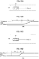
- FIG. 18A is an explanatory view illustrating a state where the host vehicle is traveling on a road with a small road width at 40 [km/h];
- FIG. 18B is a graph illustrating changes in the vehicle speed in the case where the vehicle speed is increased from 40 [km/h] to 60 [km/h] while the vehicle is traveling on the road with a small road width;
- FIG. 18C is an explanatory view illustrating a state where the host vehicle is traveling on a road with a large road width at 40 [km/h];
- FIG. 18D is a graph illustrating changes in the vehicle speed in the case where the vehicle speed is increased from 40 [km/h] to 60 [km/h] while the vehicle is traveling on the road with a large road width;
- FIG. 19A is an explanatory view illustrating a state where the host vehicle is traveling with the inter-vehicle distance being 50 [m];
- FIG. 19B is a graph illustrating changes in the inter-vehicle distance in the case where the inter-vehicle distance is reduced from 50 [m] to 20 [m];
- FIG. 19C is an explanatory view illustrating a state where the host vehicle is traveling with the inter-vehicle distance being 100 [m];
- FIG. 19D is a graph illustrating changes in the inter-vehicle distance in the case where the inter-vehicle distance is reduced from 100 [m] to 70 [m];
- FIG. 20A is an explanatory view illustrating a state where the inter-vehicle distance is 80 [m] and another vehicle is traveling in the adjacent lane;
- FIG. 20B is a graph illustrating changes in the inter-vehicle distance in the case where there is another vehicle in the adjacent lane and the inter-vehicle distance is reduced from 80 [m] to 50 [m];
- FIG. 20C is an explanatory view illustrating a state where the inter-vehicle distance is 80 [m] and no vehicle is traveling in the adjacent lane;
- FIG. 20D is a graph illustrating changes in the inter-vehicle distance in the case where there is no vehicle in the adjacent lane and the inter-vehicle distance is reduced from 80 [m] to 50 [m];
- FIG. 21 is an explanatory view illustrating switching of the driving characteristics in the case where the host vehicle stops in the maintaining time T 1 ;
- FIG. 23 is an explanatory view illustrating manual driving characteristics and automatic driving characteristics of driving performed in a modified example of the present invention.
- FIG. 1 is a block diagram illustrating a configuration of a control device of an automatic driving vehicle according to one embodiment of the present invention.
- the control device of the automatic driving vehicle includes a travel state detection unit 1 , an individual-matched driving characteristic determination unit 4 , a driving characteristic database 7 , an automatic driving characteristic determination unit 8 , and a switching parameter setting unit 11 .
- the control device of the automatic driving vehicle when driving is switched to automatic driving during travel in manual driving at a time point t 0 , automatic driving based on manual driving characteristics is performed for a manual characteristic maintaining time T 1 (hereafter, referred to as “maintaining time T 1 ” for short) obtained by a method described later.
- the manual driving characteristics described herein are driving characteristics in the manual driving by an occupant.
- the manual driving characteristics include vehicle speed, acceleration, an inter-vehicle distance, steering acceleration, a yaw rate, and the like.
- the manual driving characteristics are not limited to those described above and any characteristics generally used to indicate characteristics of the vehicle can be employed.
- the driving characteristics are gradually switched to automatic driving characteristics in a driving characteristic switching time T 2 (hereafter, referred to as “switching time T 2 ” for short) obtained by the method described later and, at time t 2 , are completely changed to the automatic driving characteristics.
- the automatic driving characteristics described herein are driving characteristics different from the manual driving characteristics.
- the automatic driving characteristics may be characteristics set by learning the characteristics of the manual driving by the occupant or characteristics set for each travel scene (normal road, expressway, or the like) and any conventional driving characteristics of automatic driving may be used.
- the vehicle speed (curve q 11 ) and the inter-vehicle distance (curve q 12 ) are given as examples of physical amounts of the automatic driving vehicle.
- the driving characteristics in the automatic driving are illustrated to be switched from the manual driving characteristics to the automatic driving characteristics
- the method of changing the driving characteristics is not limited to this and may be any method as long as the driving characteristics in the automatic driving are changed from the driving characteristics in the manual driving to driving characteristics different from these.
- the functions described in the embodiment can be implemented by one or multiple processing circuits.
- the processing circuit includes a processing device with an electric circuit.
- the processing device also includes devices such as an application-specific integrated circuit (ASIC) and conventional circuit parts designed to execute the functions described in the embodiment.
- ASIC application-specific integrated circuit
- the travel state detection unit 1 includes a host vehicle state detection unit 2 which detects the state of the host vehicle and a surrounding state detection unit 3 which detects a surrounding state.
- the host vehicle state detection unit 2 obtains vehicle speed data detected by a vehicle speed sensor 32 , acceleration data detected by an acceleration sensor 33 , and steering angle data detected by a steering angle sensor 34 , and detects the travel state of the host vehicle based on these pieces of data.
- the pieces of data detected in the host vehicle state detection unit 2 are outputted to a manual driving learning unit 5 and an automatic driving learning unit 9 illustrated in FIG. 1 .
- the surrounding state detection unit 3 includes an inter-vehicle space detection unit 35 , a non-vehicle object detection unit 36 , a surrounding vehicle type detection unit 37 , a lane detection unit 38 , a road type detection unit 39 , and a traffic information detection unit 40 .
- the inter-vehicle space detection unit 35 detects front, rear, left, and right inter-vehicle spaces of the host vehicle by using radar or the like.
- the non-vehicle object detection unit 36 detects objects other than vehicles such as pedestrians and bicycles in the surroundings of the host vehicle, based on images captured by cameras configured to capture images of the surroundings.
- the surrounding vehicle type detection unit 37 detects types of the vehicles in the surroundings of the host vehicle from the images captured by the cameras. For example, the surrounding vehicle type detection unit 37 detects passenger cars, trucks, buses, motorcycles, and the like.
- the lane detection unit 38 detects lanes in the road from the images captured by the cameras.
- the road type detection unit 39 detects the type of the road from information obtained from the navigation device.
- the traffic information detection unit 40 detects traffic information from information obtained by the navigation device. Note that various pieces of information can be detected by means of communication between the vehicles or communication between the vehicle and the road or can be detected by using sonars or the like.
- the data detected by the surrounding state detection unit 3 is outputted to the manual driving learning unit 5 and the automatic driving learning unit 9 illustrated in FIG. 1 .
- the individual-matched driving characteristic determination unit 4 includes the manual driving learning unit 5 and a manual driving characteristic setting unit 6 .
- the automatic driving characteristic determination unit 8 includes the automatic driving learning unit 9 and an automatic driving characteristic setting unit 10 .
- the manual driving learning unit 5 and the automatic driving learning unit 9 determine the type of road on which the vehicle is traveling from various pieces of data (data obtained by the sensors illustrated in FIG. 3 ) indicating the travel state and detected in the travel state detection unit 1 in the manual driving and learn the driving characteristics of the occupant for each road type.
- the driving characteristics include vehicle speed, average vehicle speed, acceleration, a yaw rate, braking timing, timing of lane change, a merging point and merging speed upon entering an expressway, and the like in the case where the occupant (for example, driver) is manually driving the vehicle.
- Performing the automatic driving based on the learned driving characteristics causes the automatic driving to be performed based on the characteristics of the occupant and uneasiness felt by the occupant in the automatic driving can be reduced.
- the learned driving characteristics may be, for example, in the case of the vehicle speed, one value such as vehicle speed 50 km/h or a range such as 30 km/h to 60 km/h.
- the driving characteristics may be expressed by using a function such as a probability density distribution. Note that, when the occupant instructs changing of the driving characteristics during the automatic driving, the manual driving learning unit 5 and the automatic driving learning unit 9 may learn the instructed driving characteristics and reflect the instructed driving characteristics in the driving characteristics of automatic driving hereafter.
- FIG. 5 is an explanatory view illustrating the three learning methods.
- learning is performed by means of human analysis.
- a learning method “ 2 ” hypothesizes are set based on human knowledge and experience and then learning is performed by means of machine learning.
- a learning method “ 3 ” learning is fully and automatically performed by means of machine learning. In the embodiment, learning is performed with the learning method “ 2 ” employed as an example.
- FIG. 6 is an explanatory view illustrating a flow of learning the characteristics from the data detected by the travel state detection unit 1 .
- the manual driving learning unit 5 and the automatic driving learning unit 9 collect pieces of data from the travel state detection unit 1 .
- the travel state and the surrounding state of the host vehicle are collected as the pieces of data.
- the manual driving learning unit 5 and the automatic driving learning unit 9 extract necessary pieces of attribute data. Not all pieces of data collected by the travel state detection unit 1 are necessarily related to the driving action and, when pieces of data not related to the driving action are used as learning materials, such pieces of data may have adverse effects on the learning result. Accordingly, only the necessary pieces of data (attribute data) are extracted in the processing of step a 2 .
- step a 3 the manual driving learning unit 5 and the automatic driving learning unit 9 correct the pieces of attribute data extracted in the aforementioned processing of step a 2 by removing elements such as noise which are included in the pieces of attribute data and which have adverse effects on learning.
- step a 4 the manual driving learning unit 5 and the automatic driving learning unit 9 classifies the pieces of attribute data into meaningful items (parameters).
- FIG. 8 illustrates an example in which pieces of data on other vehicles are classified into the meaningful items.
- the manual driving learning unit 5 and the automatic driving learning unit 9 re-classifies these pieces of data and obtains various items such as “the number of preceding vehicles,” the number of preceding trucks,” and “distance to each preceding vehicle.”
- steps a 1 to a 4 of FIG. 6 are defined as preprocessing and, in step a 5 , the manual driving learning unit 5 and the automatic driving learning unit 9 perform machine learning while using the parameters generated in the preprocessing as inputs of the machine learning.
- SOM Self Organizing Map
- SVC Small Vector Machine Classification
- SGD Spochastic Gradient Decent
- logistic regression logistic regression
- Roads are classified into various road types (for example b 1 to b 8 ) as illustrated in FIG. 7 .
- “b 1 . expressway” is set, when traveling on a normal load with two lanes on each side, “b 2 . trunk road” is set, when traveling on a normal road with one lane on each side, “b 3 . non-trunk road” is set, and when traveling in an intersection of a normal road, “b 4 . intersection” is set.
- b 5 when the host vehicle is traveling on a normal road or an expressway and there is no preceding vehicle.
- cruise travel is set, when the host vehicle is traveling on a normal road or an expressway and there is a preceding vehicle, “b 6 . following travel” is set, when the host vehicle stops at an intersection of a normal road and then restarts, “b 7 . intersection passing” is set, and when the host vehicle turns right at an intersection of a normal road, “b 8 . right turn” is set.
- step a 6 the automatic driving learning unit 9 and the manual driving learning unit 5 save the road type determined by the learning and the driving characteristics in this road type in the driving characteristic database 7 .
- FIG. 9 is an explanatory view illustrating processing in which the automatic driving learning unit 9 and the manual driving learning unit 5 save the automatic driving characteristics and the manual driving characteristics in the driving characteristic database 7 , for example, in a scene where the host vehicle is cruising on a road with two lanes.
- the manual driving learning unit 5 and the automatic driving learning unit 9 obtain various pieces of input information from the travel state detection unit 1 .
- the manual driving learning unit 5 and the automatic driving learning unit 9 obtain positional relationships with other vehicles, road information such as speed limit, travel information of the host vehicle, and the like.
- step c 2 the automatic driving learning unit 9 and the manual driving learning unit 5 execute a machine learning algorithm based on the obtained pieces of input information as illustrated in FIG. 6 .
- the type of road on which the host vehicle is traveling is thereby determined.
- the automatic driving learning unit 9 obtains the automatic driving characteristics corresponding to the determined road type from the driving characteristic database 7 and sets them as the driving characteristics in the automatic driving.
- the manual driving learning unit 5 learns the driving characteristics together with the determined road type.
- Steps c 3 to c 5 in the automatic driving are described.
- the automatic driving learning unit 9 obtains the automatic driving characteristics corresponding to the road type and sets them as the driving characteristics in the automatic driving.
- FIG. 10(A) illustrates the case where, in a situation in which a host vehicle V 1 is cruising on a left lane of a two-lane road and other vehicles V 2 , V 3 are traveling on a right lane of this road, the speed limit is 80 [km/h] and the traveling speed of the other vehicles V 2 , V 3 is 80 [km/h].
- the automatic driving learning unit 9 sets the traveling speed of the host vehicle V 1 to 80 [km/h].
- step c 4 the automatic driving learning unit 9 learns the driving characteristics also during the automatic driving.
- the automatic driving learning unit 9 may learn the instructed driving characteristics. An instruction of the occupant in the automatic driving can be thereby reflected in the driving characteristics of automatic driving hereafter.
- the automatic driving learning unit 9 saves the driving characteristics in the automatic driving in the driving characteristic database 7 .
- the automatic driving learning unit 9 labels the pieces of saved data with the traveled road type to facilitate later reference.
- the manual driving learning unit 5 obtains the manual driving characteristics together with the determined road type. For example, assume that, as illustrated in FIG. 10B , in a situation in which a host vehicle V 1 is cruising on a left lane of a two-lane road and other vehicles V 2 , V 3 are traveling on a right lane of this road, the speed limit is 80 [km/h] and the traveling speed of the other vehicles V 2 , V 3 is 80 [km/h]. When the traveling speed of the host vehicle V 1 is 60 [km/h] in this state, the manual driving learning unit 5 determines that the occupant tends to travel at speed 75% of the speed limit in curse travel.
- the cruise travel in the embodiment is defined as travel in which a situation where the inter-vehicle time (numerical value obtained by dividing the inter-vehicle distance by the traveling speed) between the host vehicle and the preceding vehicle is two seconds or more continues for 30 seconds or more.
- step c 7 the manual driving learning unit 5 saves the driving characteristics obtained by the learning in the driving characteristic database 7 . Then, in step c 8 , the manual driving learning unit 5 labels the pieces of saved data with the traveled road type to facilitate later reference.
- the automatic driving characteristics in the automatic driving of the host vehicle and the manual driving characteristics in the manual driving can be thereby obtained by the learning and be saved in the driving characteristic database 7 .
- the switching parameter setting unit 11 illustrated in FIG. 1 includes an uneasiness-physical amount model storage 12 (model storage) and a parameter control unit 13 .
- the uneasiness-physical amount model storage 12 stores uneasiness-physical amount models to be described later.
- the parameter control unit 13 estimates the uneasiness felt by the occupant and sets the maintaining time T 1 illustrated in FIG. 2 and the switching time T 2 taken for switching to the automatic driving characteristics performed after a lapse of the maintaining time T 1 , depending on the estimated uneasiness.
- the uneasiness-physical amount model storage 12 stores the uneasiness-physical amount models indicating relationships between the physical amounts in travel of the host vehicle and the uneasiness felt by the occupant.
- FIG. 11 is an explanatory view illustrating the uneasiness-physical amount models.
- the vehicle speed (or the inter-vehicle distance) and the amount of vehicle speed perceived by the occupant change as illustrated by the curve Q 1 .
- the horizontal axis of the graph 61 represents the vehicle speed (or the inter-vehicle distance) and the vertical axis represents the perceived amount of the vehicle speed (or the inter-vehicle distance).
- the perceived amount changes from e 1 to e 2 when the vehicle speed changes from d 1 (for example, 20 [km/h]) to d 2 (for example, 40 [km/h]).
- the perceived amount changes from e 2 to e 3 when the vehicle speed changes from d 2 to d 3 (for example, 60 [km/h]).
- the speed increase is 20 [km/h] in both cases
- the change in the perceived amount from e 1 to e 2 is greater than the change in the perceived amount from e 2 to e 3 . This means that the occupant feels that a greater change is occurring in the speed increase of the vehicle from d 1 to d 2 than in the speed increase from d 2 to d 3 .
- the horizontal axis of the graph 61 is the inter-vehicle distance between the host vehicle and the preceding vehicle
- the change in the amount perceived by the occupant in the case where the inter-vehicle distance decreases by 5 m from 10 m to 5 m is greater than that in the case where the inter-vehicle distance decreases by 5 m from 15 m to 10 m.
- the graph 62 illustrates relationships between the perceived amount of the vehicle speed and the uneasiness for the vehicle speed.
- the curve Q 2 illustrates characteristics in the case where the road width is small and the curve Q 3 illustrates characteristics in the case where the road width is large. It can be found that the higher the perceived amount of the vehicle speed is, the greater the uneasiness for the vehicle speed felt by the occupant is and the smaller the road width is, the greater the uneasiness is.
- a model indicating the relationships between the vehicle speed and the uneasiness for the vehicle speed is generated based on the curves Q 1 , Q 2 , and Q 3 .
- the curve Q 4 illustrates the uneasiness for the vehicle speed felt by the occupant in the case where the road width is small and the curve Q 5 illustrates that in the case where the road width is large. It can be found that the higher the vehicle speed is, the greater the uneasiness felt by the occupant is and the uneasiness is even greater when the road width is small.
- the change in the uneasiness in the case where, for example, the vehicle speed increases from 20 [km/h] to 40 [km/h] is greater than the change in the uneasiness in the case where, for example, the vehicle speed increases from 40 [km/h] to 60 [km/h].
- the speed increase is 20 [km/h] in both cases, the change in the uneasiness in the speed increase from 20 [km/h] to 40 [km/h] is greater than that in the speed increase from 40 [km/h] to 60 [km/h].
- the perceived amount of the inter-vehicle distance and the uneasiness for the inter-vehicle distance change as illustrated by the curves Q 6 and Q 7 of the graph 64 .
- the curve Q 7 illustrates characteristics in the case where there is no vehicle in an adjacent lane (case where the adjacent lane is vacant) and the curve Q 6 illustrates characteristics in the case where there is another vehicle in the adjacent lane (case where the adjacent lane is occupied). It can be found that the smaller the perceived amount of the inter-vehicle distance is (the smaller the distance to the left end of the graph of the curves Q 6 and Q 7 is), the greater the uneasiness for the inter-vehicle distance felt by the occupant is. Moreover, it can be found that the uneasiness in the case where there is another vehicle in the adjacent lane is greater than that in the case where there is no vehicle in the adjacent lane.
- a model indicating relationships between the inter-vehicle distance and the uneasiness for the inter-vehicle distance is generated based on the curves Q 1 , Q 6 , and Q 7 .
- the curve Q 8 illustrates the uneasiness for the inter-vehicle distance felt by the occupant in the case where there is another vehicle in the adjacent lane
- the curve Q 9 illustrates that in the case where there is no vehicle in the adjacent lane. It can be found that the smaller the inter-vehicle distance is, the greater the uneasiness felt by the occupant is and the uneasiness is even greater when there is another vehicle in the adjacent lane.
- the model with the aforementioned characteristics is thus generated and stored in the uneasiness-physical amount model storage 12 .
- the change in the uneasiness in the case where, for example, the inter-vehicle distance decreases from 15 [m] to 10 [m] is smaller than the change in the uneasiness in the case where, for example, the inter-vehicle distance decreases from 10 [m] to 5 [m].
- the decrease in the inter-vehicle distance is 5 [m] in both cases, the change in the uneasiness in the decrease from 15 [m] to 10 [m] is smaller than that in the decrease from 10 [m] to 5 [m].
- the uneasiness of the occupant is inputted into the parameter control unit 13 illustrated in FIG. 1 by extracting the manual driving characteristics and the automatic driving characteristics stored in the driving characteristic database 7 according to the road type determined by the machine learning and then referring to the uneasiness-physical amount models as illustrated in FIG. 12 . Then, the parameter control unit 13 sets the maintaining time T 1 and the switching time T 2 taken for the switching from the manual driving to the automatic driving, based on the inputted uneasiness.
- the uneasiness-physical amount models used in the uneasiness-physical amount model storage 12 may be set for each road type.
- the parameter control unit 13 has a function of a switching controller which performs control of switching from the manual driving to the automatic driving.
- a switching controller which performs control of switching from the manual driving to the automatic driving.
- the curve q 1 is a graph illustrating the relationships between the vehicle speed and the uneasiness felt by the occupant.
- an allowable value of a change amount of the uneasiness in the certain time is set as “allowable change amount X 1 (first threshold).”
- the vehicle speed is changed such that the change amount of the uneasiness in the certain time is less than or equal to the allowable change amount X 1 .
- a transition pattern is changed such that the increase amount of the uneasiness in the certain time less than or equal to the first threshold.
- the change amount of the uneasiness in the case where the vehicle speed increases from 20 [km/h] to 40 [km/h] is the allowable change amount X 1 . Accordingly, when the current vehicle speed is 20 [km/h], the vehicle is allowed to accelerate to 40 [km/h] in the certain time (see arrow Y 1 ).
- the speed to which the vehicle speed can be increased in the certain time is determined depending on the road width and may vary even in a speed increase from the same vehicle speed.
- the curve q 2 is a graph illustrating the relationships of the vehicle speed and the uneasiness felt by the occupant in the case where the road width is small and the curve q 3 is a graph illustrating those in the case where the road width is large.
- the distance to which the vehicle can approach the preceding vehicle in the certain time is determined depending on the inter-vehicle distance.
- the curve q 4 is a graph illustrating the relationships between the inter-vehicle distance and the uneasiness felt by the occupant.
- an allowable value of a change amount of the uneasiness in the certain time is set as “allowable change amount X 2 (first threshold).”
- the inter-vehicle distance is changed such that the change amount of the uneasiness in the certain time is less than or equal to the allowable change amount X 2 .
- the change amount of the uneasiness in the case where the inter-vehicle distance changes from 20 [m] to 10 [m] is the allowable change amount X 2 . Accordingly, when the current inter-vehicle distance is 20 [m], the vehicle is allowed to reduce the inter-vehicle distance to 10 [m] in the certain time (see arrow Y 5 ).
- the vehicle is allowed to reduce the inter-vehicle distance to 20 [m] in the certain time (see arrow Y 6 ).
- a reduction amount of the inter-vehicle distance in the certain time is determined depending on whether there is another vehicle in the adjacent lane.
- the curve q 5 illustrates the characteristics in the case where there is another vehicle in the adjacent lane and the curve q 6 illustrates the characteristics in the case where there is no vehicle in the adjacent lane.
- the vehicle When there is another vehicle in the adjacent lane, the vehicle is allowed to reduce the inter-vehicle distance from 20 [m] to 10 [m] in the certain time (see arrow Y 7 ). Meanwhile, when there is no vehicle in the adjacent lane, the vehicle is allowed to reduce the inter-vehicle distance from 35 [m] to 10 [m] in the certain time (see arrow Y 8 ).
- the parameter control unit 13 sets the maintaining time T 1 such that the greater the uneasiness is, the longer the maintaining time T 1 is. Moreover, when the vehicle speed is to be changed, the parameter control unit 13 sets the length of the switching time T 2 such that the change amount of the uneasiness in the certain time is less than or equal to the allowable change amount X 1 . Furthermore, when the inter-vehicle distance is to be changed, the parameter control unit 13 sets the length of the switching time T 2 such that the change amount of the uneasiness in the certain time is less than or equal to the allowable change amount X 2 (first threshold). This can suppress an abrupt change in the uneasiness.
- the transition pattern is set such that the lower the vehicle speed is, the longer the time taken for a speed increase (switching time T 2 ) is and the smaller the road width is, the longer the time taken for a speed increase (switching time T 2 ) is. Furthermore, the transition pattern is set such that the shorter the inter-vehicle distance is, the longer the time taken to approach the preceding vehicle (switching time T 2 ) is and, when there is another vehicle in the adjacent lane, the time taken to approach the preceding vehicle (switching time T 2 ) is longer.
- the transition pattern is set such that a decrease rate of the uneasiness is more than or equal to a preset threshold (second threshold).
- second threshold a preset threshold
- the vehicle speed of the host vehicle is reduced from 100 [km/h] to 40 [km/h] or less in the certain time and the decrease amount of the uneasiness in the certain time is thereby made greater than X 1 .
- the vehicle speed of the host vehicle is reduced from 40 [km/h] to 20 [km/h] or less in the certain time and the decrease amount of the uneasiness in the certain time is thereby made greater than X 1 .
- the control is performed such that the decrease rate of the uneasiness is more than or equal to the second threshold to quickly eliminate the uneasiness felt by the occupant.
- the inter-vehicle distance in the graph illustrated in FIG. 14A , for example, is increased from 10 [m] to 20 [m] or more in the certain time and the decrease amount of the uneasiness in the certain time is thereby made greater than X 2 .
- the inter-vehicle distance is increased from 20 [m] to 40 [m] or more in the certain time and the decrease amount of the uneasiness in the certain time is thereby made greater than X 2 .
- the transition pattern is set such that the higher the vehicle speed is, the shorter the time taken for the speed reduction (switching time T 2 ) is and the larger the road width is, the shorter the time taken for the speed reduction (switching time T 2 ) is. Moreover, the transition pattern is set such that the longer the inter-vehicle distance is, the shorter the move-away time from the preceding vehicle (switching time T 2 ) is and, when there is no vehicle in the adjacent lane, the move-away time from the preceding vehicle (switching time T 2 ) is shorter.
- the parameter control unit 13 calculates the maintaining time T 1 and also calculates the switching time T 2 to the performing of the automatic driving based on automatic driving characteristics. Moreover, the parameter control unit 13 sets the transition pattern of the driving characteristics in the switching time T 2 .
- FIG. 15 is a view illustrating an example of setting the maintaining time T 1 and the switching time T 2 .
- FIG. 15 illustrates a method of setting T 1 in the case where the control parameter for which the occupant feels uneasy is the vehicle speed and the speed is to be increased and a method of setting T 1 in the case where the control parameter is the inter-vehicle distance and the inter-vehicle distance is to be reduced.
- T 1 When the current vehicle speed is low, T 1 is set short and the switching time T 2 is set long to avoid abrupt speed increase from low speed and reduce the uneasiness of the occupant.
- T 1 When the current vehicle speed is high, T 1 is set long and the switching time T 2 is set short to quickly increase the speed. The uneasiness of the occupant can be thereby reduced.
- T 1 when the road width is small, T 1 is set long and T 2 is set long to gradually reduce the inter-vehicle distance and reduce the uneasiness of the occupant.
- T 1 When the road width is large, T 1 is set short and T 2 is set short to quickly increase the speed.
- T 1 is set long and T 2 is set long to increase the time taken to reduce the inter-vehicle distance, thereby avoiding abrupt approaching to the preceding vehicle and reducing the uneasiness of the occupant.
- T 1 is set short and T 2 is set short to quickly reduce the inter-vehicle distance.
- T 1 is set long and T 2 is set long to reduce the uneasiness of the occupant.
- T 1 is set short and T 2 is set short to quickly reduce the inter-vehicle distance.
- FIG. 16 is an explanatory view illustrating a method of setting the switching time T 2 in the case where the vehicle speed is to be changed.
- a jerk change rate in acceleration
- a bent line q 21 is determined in which jerk sections are set and the maximum jerk and the minimum jerk in these jerk sections are set.
- a section of the maximum jerk, a section of the minimum jerk, and a section where the jerk is zero have the same length.
- the bent line q 21 is integrated to obtain a bent line q 22 indicating the acceleration as illustrated in FIG. 16B .
- the bent line q 22 is integrated to obtain a curve q 23 indicating speed as illustrated in FIG. 16C .
- the curve q 23 is set such that the speed change from the current speed to a target speed forms a smooth S-shaped curve.
- time the vehicle takes to reach the target speed from the current speed is set as the switching time T 2 .
- FIG. 17 is an explanatory view illustrating a method of setting the switching time T 2 in the case where the vehicle speed is to be increased by 20 [km/h].
- FIGS. 17A and 17B illustrate the case where the vehicle speed is increased from 40 [km/h] to 60 [km/h].
- the parameter control unit 13 sets the switching time T 2 long in addition to setting the maintaining time T 1 short.
- FIGS. 17C and 17D illustrate the case where the vehicle speed is increased from 80 [km/h] to 100 [km/h].
- the parameter control unit 13 sets the switching time T 2 short in addition to setting the maintaining time T 1 long. This can reduce the uneasiness felt by the occupant. Specifically, during the switching from the manual driving to the automatic driving, the uneasiness felt by the occupant at the start of the automatic driving in the case where the vehicle speed is 80 [km/h] is greater than that in the case where the vehicle speed is 40 [km/h].
- the changing of the driving characteristics increases the uneasiness of the occupant. Accordingly, it is preferable to reduce the uneasiness of the occupant before the changing of the driving characteristics from the manual driving characteristics is started. Specifically, setting the maintaining time T 1 longer as the vehicle speed becomes higher can reduce the uneasiness of the occupant before the end of the maintaining time. Accordingly, it is possible to suppress an excessive increase in the uneasiness of the occupant while the driving characteristics are changed to the automatic driving characteristics.
- the switching time T 2 is set longer in the speed increase from 40 [km/h] to 60 [km/h] to reduce the uneasiness.
- FIG. 18 is an explanatory view illustrating a method of setting the switching time T 2 in the case where the vehicle speed is to be increased from 40 [km/h] to 60 [km/h].
- FIG. 18A illustrates the case where the host vehicle V 1 is traveling on a road with a small road width H 1 .
- the parameter control unit 13 sets the switching time T 2 long in addition to setting the maintaining time T 1 long.
- FIGS. 18C and 18D illustrate the case where a road width H 2 of a road on which the host vehicle is traveling is large.
- the parameter control unit 13 sets the switching time T 2 short in addition to setting the maintaining time T 1 short. This can reduce the uneasiness felt by the occupant. Specifically, even in the same speed increase from 40 [km/h] to 60 [km/h], the uneasiness felt by the occupant in the case where the road width is small is greater and T 1 and T 2 are thus set longer in this case to reduce the uneasiness.
- FIG. 19 is an explanatory view illustrating a method of setting the switching time T 2 in the case where the inter-vehicle distance is to be reduced by 30 [m].
- FIGS. 19A and 19B illustrate the case where the inter-vehicle distance is to be changed from 50 [m] to 20 [m].
- the parameter control unit 13 sets the switching time T 2 long in addition to setting the maintaining time T 1 long.
- FIGS. 19C and 19D illustrate the case where the inter-vehicle distance is to be changed from 100 [m] to 70 [m].
- the parameter control unit 13 sets the switching time T 2 short in addition to setting the maintaining time T 1 short. This can reduce the uneasiness felt by the occupant. Specifically, even in the same approaching of 30 [m], the uneasiness felt by the occupant in the approaching from 50 [m] to 20 [m] is greater than that in the approaching from 100 [m] to 70 [m]. Accordingly, T 1 and T 2 are set longer in the approaching from 50 [m] to 20 [m] to reduce the uneasiness.
- FIG. 20 is an explanatory view illustrating a method of setting the switching time T 2 in the case where the inter-vehicle distance is to be reduced from 80 [m] to 50 [m].
- FIGS. 20A and 20B illustrate the case where there is another vehicle in the adjacent lane. When there is another vehicle in the adjacent lane, as illustrated in FIG. 20B , the parameter control unit 13 sets the switching time T 2 long in addition to setting the maintaining time T 1 long.
- FIGS. 20C and 20D illustrate the case where there is no vehicle in the adjacent lane.
- the parameter control unit 13 sets the switching time T 2 short in addition to setting the maintaining time T 1 short. This can reduce the uneasiness felt by the occupant. Specifically, even in the same approaching from 80 [m] to 50 [m], the uneasiness felt by the occupant in the case where there is another vehicle in the adjacent lane is greater. Accordingly, T 1 and T 2 are set longer in this case to reduce the uneasiness.
- the parameter control unit 13 illustrated in FIG. 1 switches the driving characteristics to the automatic driving characteristics in restart after the stop without using the uneasiness-physical amount models.
- step S 11 the surrounding state detection unit 3 detects the surrounding state of the host vehicle.
- step S 12 the automatic driving learning unit 9 statistically learns the detected surrounding state and then, in step S 13 , classifies the current travel state. Specifically, the automatic driving learning unit 9 classifies the current travel state into one of the travel states such as travel in an expressway and travel in a normal road as illustrated in FIG. 7 .
- step S 14 the automatic driving characteristic setting unit 10 sets the automatic driving characteristics based on the current travel state by referring to the driving characteristic database 7 .
- step S 15 the host vehicle state detection unit 2 detects the current host vehicle state as illustrated in FIG. 3 .
- step S 16 the manual driving learning unit 5 statistically learns the driving characteristics of the occupant and, in step S 17 , sets the manual driving characteristics depending on the travel state. Moreover, the driving characteristics learned in the manual driving learning unit 5 are stored in the driving characteristic database 7 .
- step S 18 the parameter control unit 13 determines whether the switching operation from the manual driving to the automatic driving (override) has occurred.
- step S 19 the parameter control unit 13 determines whether the manual driving characteristics set in the processing of step S 17 are different from the automatic driving characteristics set in the processing of step S 14 .
- the manual driving characteristics are not different (NO in step S 19 )
- the occupant feels no uneasiness during the switching. Accordingly, the transition to the automatic driving control in the automatic driving characteristics is performed as it is.
- step S 20 the parameter control unit 13 refers to the uneasiness-physical amount model storage 12 and, in step S 21 , sets the maintaining time T 1 and the switching time T 2 by using the aforementioned method.
- step S 22 the parameter control unit 13 performs the automatic drive control by using the manual driving characteristics.
- step S 23 the parameter control unit 13 determines whether T 1 has elapsed.
- T 1 has elapsed (YES in step S 23 )
- step S 24 the parameter control unit 13 gradually switches the driving characteristics from the manual driving characteristics to the automatic driving characteristics.
- step S 25 the parameter control unit 13 determines whether T 2 has elapsed. When T 2 has elapsed (YES in step S 25 ), the parameter control unit 13 performs the automatic driving control.
- the switching of driving can be performed without causing the occupant to feel uneasy by appropriately setting the maintaining time T 1 and the switching time T 2 .
- the automatic driving is performed with the manual driving characteristics maintained, the manual driving characteristics being the driving characteristics in the manual driving. Accordingly, it is possible to avoid the case where the occupant feels uneasy.
- the maintaining time T 1 (manual driving maintaining time) is set to maintain the manual driving characteristics for the maintaining time T 1 and then the switching to the automatic driving characteristics is performed. Accordingly, it is possible to avoid the case where the occupant feels uneasy.
- the maintaining time T 1 is set based on the relationships between the physical amounts (vehicle speed, inter-vehicle distance, and the like) of the automatic driving vehicle and the uneasiness of the occupant. Accordingly, it is possible to set appropriate maintaining time T 1 depending on the travel state of the automatic driving vehicle.
- the maintaining time T 1 is set long. Accordingly, it is possible to more appropriately set the maintaining time T 1 and avoid the case where the occupant feels uneasy.
- the maintaining time T 1 is set long. Accordingly, it is possible to more appropriately set the maintaining time T 1 and avoid the case where the occupant feels uneasy.
- the maintaining time T 1 is set long. Accordingly, it is possible to more appropriately set the maintaining time T 1 and avoid the case where the occupant feels uneasy.
- the maintaining time T 1 is set long. Accordingly, it is possible to more appropriately set the maintaining time T 1 and avoid the case where the occupant feels uneasy.
- the maintaining time T 1 is set based on the uneasiness felt by the occupant. Accordingly, the manual driving characteristics can be maintained without the occupant feeling great uneasiness.
- the automatic driving is performed with the driving characteristics in the manual driving maintained and then the automatic driving is performed based on the automatic driving characteristics different from the manual driving characteristics. Accordingly, switching to the automatic driving characteristics can be performed without the occupant feeling uneasy.
- the transition from the manual driving characteristics to the automatic driving characteristics is performed such that the increase amount of the uneasiness in the certain time is less than or equal to the first threshold. Accordingly, uneasiness due to abrupt changes in the driving characteristics can be suppressed.
- the transition from the manual driving characteristics to the automatic driving characteristics is performed such that the time taken for the speed increase (driving characteristic switching time T 2 ) is long. Accordingly, it is possible to appropriately set the driving characteristic switching time T 2 and suppress an abrupt change in uneasiness.
- the transition from the manual driving characteristics to the automatic driving characteristics is performed such that the time taken for the speed increase (driving characteristic switching time T 2 ) is long. Accordingly, it is possible to appropriately set the driving characteristic switching time T 2 and suppress an abrupt change in uneasiness.
- the transition from the manual driving characteristics to the automatic driving characteristics is performed such that the time taken to approach the preceding vehicle (driving characteristic switching time T 2 ) is long. Accordingly, it is possible to appropriately set the driving characteristic switching time T 2 and suppress an abrupt change in uneasiness.
- the transition from the manual driving characteristics to the automatic driving characteristics is performed such that the time taken to approach the preceding vehicle (driving characteristic switching time T 2 ) is long. Accordingly, it is possible to appropriately set the driving characteristic switching time T 2 and suppress an abrupt change in uneasiness.
- the transition from the manual driving characteristics to the automatic driving characteristics is performed such that the decrease amount of the uneasiness in the certain time is more than or equal to the second threshold. Accordingly, the driving characteristics can be quickly switched.
- the transition from the manual driving characteristics to the automatic driving characteristics is performed such that the higher the vehicle speed is, the shorter the time taken for the speed reduction (driving characteristic switching time T 2 ) is. Accordingly, it is possible to quickly perform the switching and appropriately set the driving characteristic switching time T 2 .
- the transition from the manual driving characteristics to the automatic driving characteristics is performed such that the larger the road width is, the shorter the time taken for the speed reduction (driving characteristic switching time T 2 ) is. Accordingly, it is possible to quickly perform switching and appropriately set the driving characteristic switching time T 2 .
- the transition from the manual driving characteristics to the automatic driving characteristics is performed such that the longer the inter-vehicle distance is, the shorter the time to taken move away from the preceding vehicle (driving characteristic switching time T 2 ) is. Accordingly, it is possible to quickly perform the switching and appropriately set the driving characteristic switching time T 2 .
- the transition from the manual driving characteristics to the automatic driving characteristics is performed such that, when there is no vehicle in the adjacent lane, the time to taken move away from the preceding vehicle (driving characteristic switching time T 2 ) is short. Accordingly, it is possible to quickly perform the switching and appropriately set the driving characteristic switching time T 2 .
- FIG. 23 is an explanatory view illustrating the modified example.
- a braking operation is performed before each curve.
- the timing of the braking operation in the travel in the manual driving may vary from that in the travel based on the automatic driving characteristics.
- reference signs x 1 to x 5 each denote the timing of braking operation based on the automatic driving characteristics.
- reference signs w 1 to w 5 each denote timing of actual braking operation. In this case, the timing of braking operation is the physical amount of the host vehicle.
- the braking operation is performed at the reference sign w 1 which is the braking operation timing based on the manual driving characteristics.
- the reference sign w 1 has a time difference ⁇ t 1 to the reference value x 1 which is the timing based on the automatic driving characteristics.
- the time difference ⁇ t 1 is maintained in the maintaining time T 1 .
- the time difference between the reference signs w 2 and x 2 is ⁇ t 1 .
- the switching time T 2 the time difference is gradually reduced such as time differences ⁇ t 2 ( ⁇ t 1 ) and ⁇ t 3 ( ⁇ t 2 ). Then, after the switching time T 2 elapses, the reference signs w 5 and x 5 are made to coincide with each other. The switching from the manual driving to the driving based on the automatic driving characteristics can be thereby performed without causing the occupant to feel uneasy.
- control method and the control device of the automatic driving vehicle of the present invention have been described above based on the illustrated embodiment, the present invention is not limited to the embodiment.
- the configuration of each part may be replaced by any configuration having a similar function.
Landscapes
- Engineering & Computer Science (AREA)
- Transportation (AREA)
- Mechanical Engineering (AREA)
- Automation & Control Theory (AREA)
- Chemical & Material Sciences (AREA)
- Combustion & Propulsion (AREA)
- Human Computer Interaction (AREA)
- Physics & Mathematics (AREA)
- Mathematical Physics (AREA)
- Traffic Control Systems (AREA)
- Control Of Driving Devices And Active Controlling Of Vehicle (AREA)
- Remote Sensing (AREA)
- Aviation & Aerospace Engineering (AREA)
- General Physics & Mathematics (AREA)
- Radar, Positioning & Navigation (AREA)
- Artificial Intelligence (AREA)
- Game Theory and Decision Science (AREA)
- Medical Informatics (AREA)
- Evolutionary Computation (AREA)
- Health & Medical Sciences (AREA)
- Business, Economics & Management (AREA)
- Steering Control In Accordance With Driving Conditions (AREA)
- Control Of Vehicle Engines Or Engines For Specific Uses (AREA)
Applications Claiming Priority (1)
| Application Number | Priority Date | Filing Date | Title |
|---|---|---|---|
| PCT/JP2016/073327 WO2018029758A1 (ja) | 2016-08-08 | 2016-08-08 | 自動運転車両の制御方法及び制御装置 |
Publications (2)
| Publication Number | Publication Date |
|---|---|
| US20190171204A1 US20190171204A1 (en) | 2019-06-06 |
| US10606264B2 true US10606264B2 (en) | 2020-03-31 |
Family
ID=61162820
Family Applications (1)
| Application Number | Title | Priority Date | Filing Date |
|---|---|---|---|
| US16/323,744 Active US10606264B2 (en) | 2016-08-08 | 2016-08-08 | Control method and control device of automatic driving vehicle |
Country Status (10)
| Country | Link |
|---|---|
| US (1) | US10606264B2 (ja) |
| EP (1) | EP3498556B1 (ja) |
| JP (1) | JP6677304B2 (ja) |
| KR (1) | KR102026058B1 (ja) |
| CN (1) | CN109562758B (ja) |
| BR (1) | BR112019002546B1 (ja) |
| CA (1) | CA3033164C (ja) |
| MX (1) | MX2019001525A (ja) |
| RU (1) | RU2705480C1 (ja) |
| WO (1) | WO2018029758A1 (ja) |
Families Citing this family (27)
| Publication number | Priority date | Publication date | Assignee | Title |
|---|---|---|---|---|
| CA3068410A1 (en) * | 2017-06-26 | 2019-01-03 | Nissan Motor Co., Ltd. | Vehicle traveling assistance method and vehicle traveling assistance device |
| CN111108031B (zh) * | 2017-08-30 | 2023-09-22 | 本田技研工业株式会社 | 行驶控制装置、车辆以及行驶控制方法 |
| JP6988381B2 (ja) * | 2017-11-06 | 2022-01-05 | トヨタ自動車株式会社 | 車両制御装置 |
| JP6628819B2 (ja) * | 2018-01-15 | 2020-01-15 | 本田技研工業株式会社 | 車両走行制御装置 |
| JP6874731B2 (ja) * | 2018-04-11 | 2021-05-19 | トヨタ自動車株式会社 | 車両制御装置 |
| JP7127343B2 (ja) * | 2018-04-13 | 2022-08-30 | 株式会社デンソー | 運転モード切替装置、運転モードの切替方法、コンピュータプログラム |
| DE102018206425A1 (de) * | 2018-04-25 | 2019-10-31 | Bayerische Motoren Werke Aktiengesellschaft | Aktivierung einer Fahrfunktion zum automatisierten Fahren mit Längs- und Querführung über eine andere Fahrfunktion zum automatisierten Fahren mit geringem Automatisierungsgrad |
| US10635104B2 (en) * | 2018-08-21 | 2020-04-28 | International Business Machines Corporation | Intelligent transitioning between autonomous and manual driving modes of a vehicle |
| JP2022031987A (ja) * | 2018-10-26 | 2022-02-24 | 日立Astemo株式会社 | 車両駆動制御装置、車両の駆動制御方法及びプログラム |
| US11325611B2 (en) | 2018-12-26 | 2022-05-10 | Baidu Usa Llc | Torque feedback based vehicle longitudinal automatic calibration system for autonomous driving vehicles |
| US11126178B2 (en) | 2019-01-18 | 2021-09-21 | Zoox, Inc. | Vehicle control |
| DE102019101662A1 (de) * | 2019-01-23 | 2020-07-23 | Bayerische Motoren Werke Aktiengesellschaft | Verfahren und Steuereinheit zum Betrieb eines adaptiven Geschwindigkeitsreglers |
| KR102180800B1 (ko) * | 2019-04-03 | 2020-11-19 | 경북대학교 산학협력단 | 차량의 주행상태 판단장치 및 그 판단방법 |
| JP7143822B2 (ja) * | 2019-06-28 | 2022-09-29 | トヨタ自動車株式会社 | 車両制御装置 |
| US10696306B1 (en) | 2019-09-25 | 2020-06-30 | Lyft Inc. | Evaluating driving control systems for elegant driving |
| JP7255699B2 (ja) * | 2019-10-09 | 2023-04-11 | 株式会社Soken | 車両用運転切り替え装置、車両運転システム、車両用運転切り替え方法 |
| DE102020100868A1 (de) * | 2020-01-15 | 2021-07-15 | Bayerische Motoren Werke Aktiengesellschaft | Verfahren und Steuereinheit zum Betrieb einer Fahrfunktion |
| US11827503B2 (en) | 2020-03-18 | 2023-11-28 | Crown Equipment Corporation | Adaptive acceleration for materials handling vehicle |
| CN111861128B (zh) * | 2020-06-20 | 2024-03-22 | 清华大学 | 自动驾驶车辆人机协同操纵过程的接管舒适性评价方法、系统及存储介质 |
| US11608067B2 (en) * | 2020-08-12 | 2023-03-21 | Honda Motor Co., Ltd. | Probabilistic-based lane-change decision making and motion planning system and method thereof |
| CN112339754A (zh) * | 2020-10-23 | 2021-02-09 | 上汽通用五菱汽车股份有限公司 | 车速调整方法、车辆及可读存储介质 |
| MX2023005183A (es) * | 2020-11-03 | 2023-05-15 | Crown Equip Corp | Aceleracion adaptativa para vehiculo de manejo de materiales. |
| JP7184949B2 (ja) * | 2021-03-26 | 2022-12-06 | 本田技研工業株式会社 | 自動運転車両の操舵装置及びこれを備えた自動運転車両 |
| FR3126385B1 (fr) * | 2021-08-25 | 2023-10-06 | Psa Automobiles Sa | Procédé et système pour personnaliser le fonctionnement d’un appareillage d’aide à la conduite d’un véhicule automobile |
| WO2023059221A1 (ru) | 2021-10-04 | 2023-04-13 | Общество с ограниченной ответственностью "ЭвоКарго" | Способ управления характеристиками движения транспортного средства |
| FR3132070B1 (fr) * | 2022-01-21 | 2023-12-15 | Psa Automobiles Sa | Procédé et dispositif de contrôle d’accélération d’un véhicule embarquant un système de régulation de vitesse |
| CN116674578B (zh) * | 2023-08-03 | 2023-10-20 | 南京德沃克自动化有限公司 | 基于车辆显控系统的控制方法及系统 |
Citations (17)
| Publication number | Priority date | Publication date | Assignee | Title |
|---|---|---|---|---|
| JPH03282713A (ja) | 1990-03-30 | 1991-12-12 | Mazda Motor Corp | 自律走行車両の制御装置 |
| US5197563A (en) | 1990-06-08 | 1993-03-30 | Jidosha Denki Kogyo Kabushiki Kaisha | Constant-speed cruising control system for vehicles |
| JPH10238617A (ja) | 1997-02-26 | 1998-09-08 | Mitsubishi Motors Corp | 車両用自動変速機の変速制御装置 |
| JPH10309961A (ja) | 1997-05-12 | 1998-11-24 | Toyota Motor Corp | 自動走行車両制御装置 |
| JP2010012852A (ja) | 2008-07-02 | 2010-01-21 | Aisin Aw Co Ltd | 運転支援装置、運転支援方法および運転支援プログラム |
| US7894951B2 (en) | 2005-10-21 | 2011-02-22 | Deere & Company | Systems and methods for switching between autonomous and manual operation of a vehicle |
| JP2012051441A (ja) | 2010-08-31 | 2012-03-15 | Toyota Motor Corp | 自動運転車両制御装置 |
| JP2014180894A (ja) | 2013-03-18 | 2014-09-29 | Yanmar Co Ltd | 走行車両 |
| EP2813408A1 (de) | 2013-06-12 | 2014-12-17 | Robert Bosch Gmbh | Verfahren und Vorrichtung zum Betreiben eines Fahrzeugs |
| JP2015024746A (ja) | 2013-07-26 | 2015-02-05 | 日産自動車株式会社 | 自動運転制御装置及び自動運転制御方法 |
| US20150166063A1 (en) | 2013-12-18 | 2015-06-18 | Jtekt Corporation | Vehicle control apparatus and vehicle control method |
| JP2015133050A (ja) | 2014-01-15 | 2015-07-23 | みこらった株式会社 | 自動運転車 |
| WO2016013325A1 (ja) | 2014-07-25 | 2016-01-28 | アイシン・エィ・ダブリュ株式会社 | 自動運転支援システム、自動運転支援方法及びコンピュータプログラム |
| US20160159251A1 (en) | 2013-07-23 | 2016-06-09 | Nissan Motor Co., Ltd. | Vehicle driving support device and vehicle driving support method |
| WO2016090282A1 (en) | 2014-12-05 | 2016-06-09 | Cowbyt Technologies Llc | Autonomous navigation system |
| WO2016109540A1 (en) | 2014-12-29 | 2016-07-07 | Robert Bosch Gmbh | Systems and methods for operating autonomous vehicles using personalized driving profiles |
| US20180259956A1 (en) * | 2015-09-30 | 2018-09-13 | Sony Corporation | Driving control apparatus, driving control method, and program |
Family Cites Families (4)
| Publication number | Priority date | Publication date | Assignee | Title |
|---|---|---|---|---|
| JP4973687B2 (ja) * | 2009-05-13 | 2012-07-11 | トヨタ自動車株式会社 | 走行支援装置 |
| RU2477527C1 (ru) * | 2012-03-27 | 2013-03-10 | Павел Ильич Субботин | Способ и система управления транспортными потоками и устройство мониторинга дорожной ситуации |
| US8825258B2 (en) * | 2012-11-30 | 2014-09-02 | Google Inc. | Engaging and disengaging for autonomous driving |
| EP3812962A1 (en) * | 2013-12-04 | 2021-04-28 | Mobileye Vision Technologies Ltd. | Navigating a vehicle to pass another vehicle |
-
2016
- 2016-08-08 KR KR1020197002501A patent/KR102026058B1/ko active IP Right Grant
- 2016-08-08 BR BR112019002546-4A patent/BR112019002546B1/pt active IP Right Grant
- 2016-08-08 WO PCT/JP2016/073327 patent/WO2018029758A1/ja unknown
- 2016-08-08 JP JP2018533321A patent/JP6677304B2/ja active Active
- 2016-08-08 EP EP16912642.2A patent/EP3498556B1/en active Active
- 2016-08-08 CN CN201680088137.4A patent/CN109562758B/zh active Active
- 2016-08-08 US US16/323,744 patent/US10606264B2/en active Active
- 2016-08-08 MX MX2019001525A patent/MX2019001525A/es active IP Right Grant
- 2016-08-08 RU RU2019104754A patent/RU2705480C1/ru active
- 2016-08-08 CA CA3033164A patent/CA3033164C/en active Active
Patent Citations (20)
| Publication number | Priority date | Publication date | Assignee | Title |
|---|---|---|---|---|
| JPH03282713A (ja) | 1990-03-30 | 1991-12-12 | Mazda Motor Corp | 自律走行車両の制御装置 |
| US5197563A (en) | 1990-06-08 | 1993-03-30 | Jidosha Denki Kogyo Kabushiki Kaisha | Constant-speed cruising control system for vehicles |
| JPH10238617A (ja) | 1997-02-26 | 1998-09-08 | Mitsubishi Motors Corp | 車両用自動変速機の変速制御装置 |
| JPH10309961A (ja) | 1997-05-12 | 1998-11-24 | Toyota Motor Corp | 自動走行車両制御装置 |
| US7894951B2 (en) | 2005-10-21 | 2011-02-22 | Deere & Company | Systems and methods for switching between autonomous and manual operation of a vehicle |
| JP2010012852A (ja) | 2008-07-02 | 2010-01-21 | Aisin Aw Co Ltd | 運転支援装置、運転支援方法および運転支援プログラム |
| JP2012051441A (ja) | 2010-08-31 | 2012-03-15 | Toyota Motor Corp | 自動運転車両制御装置 |
| JP2014180894A (ja) | 2013-03-18 | 2014-09-29 | Yanmar Co Ltd | 走行車両 |
| EP2813408A1 (de) | 2013-06-12 | 2014-12-17 | Robert Bosch Gmbh | Verfahren und Vorrichtung zum Betreiben eines Fahrzeugs |
| US20140371981A1 (en) | 2013-06-12 | 2014-12-18 | Robert Bosch Gmbh | Method and apparatus for operating a vehicle |
| US20160159251A1 (en) | 2013-07-23 | 2016-06-09 | Nissan Motor Co., Ltd. | Vehicle driving support device and vehicle driving support method |
| JP2015024746A (ja) | 2013-07-26 | 2015-02-05 | 日産自動車株式会社 | 自動運転制御装置及び自動運転制御方法 |
| US20150166063A1 (en) | 2013-12-18 | 2015-06-18 | Jtekt Corporation | Vehicle control apparatus and vehicle control method |
| JP2015116919A (ja) | 2013-12-18 | 2015-06-25 | 株式会社ジェイテクト | 車両制御装置 |
| JP2015133050A (ja) | 2014-01-15 | 2015-07-23 | みこらった株式会社 | 自動運転車 |
| WO2016013325A1 (ja) | 2014-07-25 | 2016-01-28 | アイシン・エィ・ダブリュ株式会社 | 自動運転支援システム、自動運転支援方法及びコンピュータプログラム |
| US20170203770A1 (en) | 2014-07-25 | 2017-07-20 | Aisin Aw Co., Ltd. | Automatic drive assist system, automatic drive assist method, and computer program |
| WO2016090282A1 (en) | 2014-12-05 | 2016-06-09 | Cowbyt Technologies Llc | Autonomous navigation system |
| WO2016109540A1 (en) | 2014-12-29 | 2016-07-07 | Robert Bosch Gmbh | Systems and methods for operating autonomous vehicles using personalized driving profiles |
| US20180259956A1 (en) * | 2015-09-30 | 2018-09-13 | Sony Corporation | Driving control apparatus, driving control method, and program |
Also Published As
| Publication number | Publication date |
|---|---|
| RU2705480C1 (ru) | 2019-11-07 |
| JP6677304B2 (ja) | 2020-04-08 |
| EP3498556A1 (en) | 2019-06-19 |
| CN109562758A (zh) | 2019-04-02 |
| KR20190022759A (ko) | 2019-03-06 |
| EP3498556B1 (en) | 2020-10-07 |
| BR112019002546B1 (pt) | 2023-01-17 |
| WO2018029758A1 (ja) | 2018-02-15 |
| MX2019001525A (es) | 2019-07-04 |
| JPWO2018029758A1 (ja) | 2019-06-06 |
| CN109562758B (zh) | 2020-07-17 |
| BR112019002546A2 (pt) | 2019-05-21 |
| US20190171204A1 (en) | 2019-06-06 |
| KR102026058B1 (ko) | 2019-11-05 |
| CA3033164A1 (en) | 2018-02-15 |
| CA3033164C (en) | 2020-03-24 |
| EP3498556A4 (en) | 2019-09-11 |
Similar Documents
| Publication | Publication Date | Title |
|---|---|---|
| US10606264B2 (en) | Control method and control device of automatic driving vehicle | |
| US11718297B1 (en) | Modifying a vehicle state based on the presence of a special-purpose vehicle | |
| CN110001643B (zh) | 车辆控制装置、车辆控制方法、存储介质、以及信息获取装置 | |
| JP6572847B2 (ja) | 自動運転システム | |
| JP6428928B2 (ja) | オクルージョン制御装置 | |
| US10671071B2 (en) | Control method and control device of automatic driving vehicle | |
| CN110692094B (zh) | 用于自动驾驶车的控制的车辆控制装置及方法 | |
| CN108349494B (zh) | 运行车辆的距离和速度调整功能的方法和执行该方法的驾驶员辅助系统 | |
| JP6801116B2 (ja) | 走行制御装置、車両および走行制御方法 | |
| JP2015000722A (ja) | 車両作動方法および車両作動装置 | |
| JPWO2017203694A1 (ja) | 運転制御方法及び運転制御装置 | |
| KR20150061781A (ko) | 차량 코너링 제어 방법 및 그 장치 | |
| JP2018025977A (ja) | 自動運転システム | |
| CN108604413B (zh) | 显示装置的控制方法及显示装置 | |
| JP6558356B2 (ja) | 自動運転システム | |
| CN108995646B (zh) | 一种应用于自动驾驶车辆的车道保持方法及装置 | |
| JPWO2018220851A1 (ja) | 自動運転車の制御のための車両制御装置及び方法 | |
| CN111587206B (zh) | 车辆控制装置、具有该车辆控制装置的车辆以及控制方法 | |
| CN114559940A (zh) | 车辆换道方法、装置及车辆 | |
| CN111824003A (zh) | 一种车灯的控制方法及控制系统 | |
| US10766412B1 (en) | Systems and methods for notifying other road users of a change in vehicle speed | |
| US20200023863A1 (en) | Concentration degree determination device, concentration degree determination method, and program for determining concentration degree | |
| JP2023133522A (ja) | 画像処理装置、撮像装置、移動体、および画像処理方法 | |
| CN116653942A (zh) | 用于控制车辆选择行车道的方法、系统和计算机程序产品 | |
| JP2021183444A (ja) | 車両制御装置 |
Legal Events
| Date | Code | Title | Description |
|---|---|---|---|
| AS | Assignment |
Owner name: NISSAN MOTOR CO., LTD., JAPAN Free format text: ASSIGNMENT OF ASSIGNORS INTEREST;ASSIGNORS:JANG, HWASEON;SUNDA, TAKASHI;HIRAMATSU, MACHIKO;SIGNING DATES FROM 20181128 TO 20181218;REEL/FRAME:048256/0242 |
|
| FEPP | Fee payment procedure |
Free format text: ENTITY STATUS SET TO UNDISCOUNTED (ORIGINAL EVENT CODE: BIG.); ENTITY STATUS OF PATENT OWNER: LARGE ENTITY |
|
| STPP | Information on status: patent application and granting procedure in general |
Free format text: APPLICATION DISPATCHED FROM PREEXAM, NOT YET DOCKETED |
|
| STPP | Information on status: patent application and granting procedure in general |
Free format text: DOCKETED NEW CASE - READY FOR EXAMINATION |
|
| STPP | Information on status: patent application and granting procedure in general |
Free format text: NON FINAL ACTION MAILED |
|
| STPP | Information on status: patent application and granting procedure in general |
Free format text: RESPONSE TO NON-FINAL OFFICE ACTION ENTERED AND FORWARDED TO EXAMINER |
|
| STPP | Information on status: patent application and granting procedure in general |
Free format text: NOTICE OF ALLOWANCE MAILED -- APPLICATION RECEIVED IN OFFICE OF PUBLICATIONS |
|
| STPP | Information on status: patent application and granting procedure in general |
Free format text: PUBLICATIONS -- ISSUE FEE PAYMENT RECEIVED |
|
| STPP | Information on status: patent application and granting procedure in general |
Free format text: PUBLICATIONS -- ISSUE FEE PAYMENT VERIFIED |
|
| STCF | Information on status: patent grant |
Free format text: PATENTED CASE |
|
| MAFP | Maintenance fee payment |
Free format text: PAYMENT OF MAINTENANCE FEE, 4TH YEAR, LARGE ENTITY (ORIGINAL EVENT CODE: M1551); ENTITY STATUS OF PATENT OWNER: LARGE ENTITY Year of fee payment: 4 |