US10490794B2 - Electrode-composite separator assembly for lithium battery and lithium battery including the same - Google Patents
Electrode-composite separator assembly for lithium battery and lithium battery including the same Download PDFInfo
- Publication number
- US10490794B2 US10490794B2 US15/235,302 US201615235302A US10490794B2 US 10490794 B2 US10490794 B2 US 10490794B2 US 201615235302 A US201615235302 A US 201615235302A US 10490794 B2 US10490794 B2 US 10490794B2
- Authority
- US
- United States
- Prior art keywords
- formula
- composite separator
- electrode
- repeating unit
- unit represented
- Prior art date
- Legal status (The legal status is an assumption and is not a legal conclusion. Google has not performed a legal analysis and makes no representation as to the accuracy of the status listed.)
- Active, expires
Links
- 0 C.C.C.C.C.C.[1*]C(C)(CC)C(=O)O[2*].[3*]C(C)(CC)OC([4*])=O.[5*]C(C)(CC)C(=O)O[6*] Chemical compound C.C.C.C.C.C.[1*]C(C)(CC)C(=O)O[2*].[3*]C(C)(CC)OC([4*])=O.[5*]C(C)(CC)C(=O)O[6*] 0.000 description 20
- PQXWDGVHDAUIEZ-UHFFFAOYSA-N CCCCOC(=O)C(C)(CC)CC(C)(CC(C)OC(C)=O)C(=O)OC Chemical compound CCCCOC(=O)C(C)(CC)CC(C)(CC(C)OC(C)=O)C(=O)OC PQXWDGVHDAUIEZ-UHFFFAOYSA-N 0.000 description 4
- ZOTVAFUYTZQYMS-UHFFFAOYSA-N CCCCOC(=O)C(C)(CC)CC(C)(CC(C)OC(C)=O)C(=O)OC.CCCOC(=O)C(C)(CC)CC(C)(CC(C)OC(C)=O)C(=O)OC Chemical compound CCCCOC(=O)C(C)(CC)CC(C)(CC(C)OC(C)=O)C(=O)OC.CCCOC(=O)C(C)(CC)CC(C)(CC(C)OC(C)=O)C(=O)OC ZOTVAFUYTZQYMS-UHFFFAOYSA-N 0.000 description 2
- FNSCMCLAHQBLKF-UHFFFAOYSA-N C1=C(C2=NNN=N2)C=C(C2=NNN=N2)C=C1C1=NNN=N1.C1=CC2=C(C=C1)N=CC2.C1=CC2=C(C=C1)N=NC2.C1=CN=CC1.C1=NC=NC1.C1=NNC=C1C1=CC(C2=CNN=C2)=CC(C2=CNN=C2)=C1.C1=NNN=C1C1=CC(C2=CNN=N2)=CC(C2=CNN=N2)=C1.O=C(O)/C1=C/C2=CC=C3/C=C(/C(=O)O)C=C4=CC=C(=C1)C2=C34.O=C(O)C1=CC=C(C(=O)O)C=C1.O=C(O)C1=CC=C(C2=CC(C3=CC=C(C(=O)O)C=C3)=CC(C3=CC=C(C(=O)O)C=C3)=C2)C=C1.O=P(O)(O)C1=CC=C(P(=O)(O)O)C=C1.O=S(=O)(O)C1=CC=C(S(=O)(=O)O)C=C1 Chemical compound C1=C(C2=NNN=N2)C=C(C2=NNN=N2)C=C1C1=NNN=N1.C1=CC2=C(C=C1)N=CC2.C1=CC2=C(C=C1)N=NC2.C1=CN=CC1.C1=NC=NC1.C1=NNC=C1C1=CC(C2=CNN=C2)=CC(C2=CNN=C2)=C1.C1=NNN=C1C1=CC(C2=CNN=N2)=CC(C2=CNN=N2)=C1.O=C(O)/C1=C/C2=CC=C3/C=C(/C(=O)O)C=C4=CC=C(=C1)C2=C34.O=C(O)C1=CC=C(C(=O)O)C=C1.O=C(O)C1=CC=C(C2=CC(C3=CC=C(C(=O)O)C=C3)=CC(C3=CC=C(C(=O)O)C=C3)=C2)C=C1.O=P(O)(O)C1=CC=C(P(=O)(O)O)C=C1.O=S(=O)(O)C1=CC=C(S(=O)(=O)O)C=C1 FNSCMCLAHQBLKF-UHFFFAOYSA-N 0.000 description 1
Images


Classifications
-
- H01M2/166—
-
- H—ELECTRICITY
- H01—ELECTRIC ELEMENTS
- H01M—PROCESSES OR MEANS, e.g. BATTERIES, FOR THE DIRECT CONVERSION OF CHEMICAL ENERGY INTO ELECTRICAL ENERGY
- H01M50/00—Constructional details or processes of manufacture of the non-active parts of electrochemical cells other than fuel cells, e.g. hybrid cells
- H01M50/40—Separators; Membranes; Diaphragms; Spacing elements inside cells
- H01M50/403—Manufacturing processes of separators, membranes or diaphragms
-
- C—CHEMISTRY; METALLURGY
- C08—ORGANIC MACROMOLECULAR COMPOUNDS; THEIR PREPARATION OR CHEMICAL WORKING-UP; COMPOSITIONS BASED THEREON
- C08F—MACROMOLECULAR COMPOUNDS OBTAINED BY REACTIONS ONLY INVOLVING CARBON-TO-CARBON UNSATURATED BONDS
- C08F220/00—Copolymers of compounds having one or more unsaturated aliphatic radicals, each having only one carbon-to-carbon double bond, and only one being terminated by only one carboxyl radical or a salt, anhydride ester, amide, imide or nitrile thereof
- C08F220/02—Monocarboxylic acids having less than ten carbon atoms; Derivatives thereof
- C08F220/10—Esters
- C08F220/12—Esters of monohydric alcohols or phenols
- C08F220/16—Esters of monohydric alcohols or phenols of phenols or of alcohols containing two or more carbon atoms
- C08F220/18—Esters of monohydric alcohols or phenols of phenols or of alcohols containing two or more carbon atoms with acrylic or methacrylic acids
-
- C—CHEMISTRY; METALLURGY
- C08—ORGANIC MACROMOLECULAR COMPOUNDS; THEIR PREPARATION OR CHEMICAL WORKING-UP; COMPOSITIONS BASED THEREON
- C08L—COMPOSITIONS OF MACROMOLECULAR COMPOUNDS
- C08L53/00—Compositions of block copolymers containing at least one sequence of a polymer obtained by reactions only involving carbon-to-carbon unsaturated bonds; Compositions of derivatives of such polymers
-
- H—ELECTRICITY
- H01—ELECTRIC ELEMENTS
- H01M—PROCESSES OR MEANS, e.g. BATTERIES, FOR THE DIRECT CONVERSION OF CHEMICAL ENERGY INTO ELECTRICAL ENERGY
- H01M10/00—Secondary cells; Manufacture thereof
- H01M10/05—Accumulators with non-aqueous electrolyte
- H01M10/052—Li-accumulators
-
- H—ELECTRICITY
- H01—ELECTRIC ELEMENTS
- H01M—PROCESSES OR MEANS, e.g. BATTERIES, FOR THE DIRECT CONVERSION OF CHEMICAL ENERGY INTO ELECTRICAL ENERGY
- H01M10/00—Secondary cells; Manufacture thereof
- H01M10/05—Accumulators with non-aqueous electrolyte
- H01M10/052—Li-accumulators
- H01M10/0525—Rocking-chair batteries, i.e. batteries with lithium insertion or intercalation in both electrodes; Lithium-ion batteries
-
- H—ELECTRICITY
- H01—ELECTRIC ELEMENTS
- H01M—PROCESSES OR MEANS, e.g. BATTERIES, FOR THE DIRECT CONVERSION OF CHEMICAL ENERGY INTO ELECTRICAL ENERGY
- H01M10/00—Secondary cells; Manufacture thereof
- H01M10/05—Accumulators with non-aqueous electrolyte
- H01M10/056—Accumulators with non-aqueous electrolyte characterised by the materials used as electrolytes, e.g. mixed inorganic/organic electrolytes
- H01M10/0561—Accumulators with non-aqueous electrolyte characterised by the materials used as electrolytes, e.g. mixed inorganic/organic electrolytes the electrolyte being constituted of inorganic materials only
- H01M10/0562—Solid materials
-
- H01M2/1673—
-
- H—ELECTRICITY
- H01—ELECTRIC ELEMENTS
- H01M—PROCESSES OR MEANS, e.g. BATTERIES, FOR THE DIRECT CONVERSION OF CHEMICAL ENERGY INTO ELECTRICAL ENERGY
- H01M50/00—Constructional details or processes of manufacture of the non-active parts of electrochemical cells other than fuel cells, e.g. hybrid cells
- H01M50/40—Separators; Membranes; Diaphragms; Spacing elements inside cells
- H01M50/409—Separators, membranes or diaphragms characterised by the material
- H01M50/446—Composite material consisting of a mixture of organic and inorganic materials
-
- H—ELECTRICITY
- H01—ELECTRIC ELEMENTS
- H01M—PROCESSES OR MEANS, e.g. BATTERIES, FOR THE DIRECT CONVERSION OF CHEMICAL ENERGY INTO ELECTRICAL ENERGY
- H01M50/00—Constructional details or processes of manufacture of the non-active parts of electrochemical cells other than fuel cells, e.g. hybrid cells
- H01M50/40—Separators; Membranes; Diaphragms; Spacing elements inside cells
- H01M50/46—Separators, membranes or diaphragms characterised by their combination with electrodes
-
- H—ELECTRICITY
- H01—ELECTRIC ELEMENTS
- H01M—PROCESSES OR MEANS, e.g. BATTERIES, FOR THE DIRECT CONVERSION OF CHEMICAL ENERGY INTO ELECTRICAL ENERGY
- H01M2220/00—Batteries for particular applications
- H01M2220/20—Batteries in motive systems, e.g. vehicle, ship, plane
-
- Y—GENERAL TAGGING OF NEW TECHNOLOGICAL DEVELOPMENTS; GENERAL TAGGING OF CROSS-SECTIONAL TECHNOLOGIES SPANNING OVER SEVERAL SECTIONS OF THE IPC; TECHNICAL SUBJECTS COVERED BY FORMER USPC CROSS-REFERENCE ART COLLECTIONS [XRACs] AND DIGESTS
- Y02—TECHNOLOGIES OR APPLICATIONS FOR MITIGATION OR ADAPTATION AGAINST CLIMATE CHANGE
- Y02E—REDUCTION OF GREENHOUSE GAS [GHG] EMISSIONS, RELATED TO ENERGY GENERATION, TRANSMISSION OR DISTRIBUTION
- Y02E60/00—Enabling technologies; Technologies with a potential or indirect contribution to GHG emissions mitigation
- Y02E60/10—Energy storage using batteries
-
- Y—GENERAL TAGGING OF NEW TECHNOLOGICAL DEVELOPMENTS; GENERAL TAGGING OF CROSS-SECTIONAL TECHNOLOGIES SPANNING OVER SEVERAL SECTIONS OF THE IPC; TECHNICAL SUBJECTS COVERED BY FORMER USPC CROSS-REFERENCE ART COLLECTIONS [XRACs] AND DIGESTS
- Y02—TECHNOLOGIES OR APPLICATIONS FOR MITIGATION OR ADAPTATION AGAINST CLIMATE CHANGE
- Y02T—CLIMATE CHANGE MITIGATION TECHNOLOGIES RELATED TO TRANSPORTATION
- Y02T10/00—Road transport of goods or passengers
- Y02T10/60—Other road transportation technologies with climate change mitigation effect
- Y02T10/70—Energy storage systems for electromobility, e.g. batteries
-
- Y02T10/7011—
Definitions
- the present disclosure relates to an electrode-composite separator assembly for a lithium battery, and a lithium battery including the same.
- Lithium batteries are high-performance batteries having a highest energy density among currently available secondary batteries, and are applicable in various fields such as electric vehicles.
- a lithium battery may have a structure in which a separator is disposed between a cathode and an anode.
- a polyolefin-based separator may be used as the separator.
- the polyolefin-based separator has insufficient heat resistance and needs to be further improved for use in a lithium ion battery for electric vehicles.
- an electrode-composite separator assembly for a lithium battery is provided.
- a lithium battery with improved cell performance including the electrode-composite separator assembly.
- an electrode-composite separator assembly for a lithium battery includes: an electrode; and a composite separator, wherein the composite separator includes: a copolymer including a first repeating unit represented by Formula 1, a second repeating unit represented by Formula 2, and a third repeating unit represented by Formula 3; at least one selected from an inorganic particle and an organic-inorganic particle; and at least one polymer selected from a fluorinated polymer and a heat-resistant polymer; wherein Formulas 1 to 3 are
- R 1 is a hydrogen or a C1-C5 alkyl group
- R 2 is a C2-C20 alkyl group
- R 5 is a hydrogen or a C1-C5 alkyl group
- R 6 is a methyl group
- R 3 is a hydrogen or a C1-C5 alkyl group
- R 4 is a C1-C10 alkyl group.
- a lithium battery includes the electrode-composite separator assembly.
- FIG. 1A is a schematic view illustrating a structure of a lithium battery according to an embodiment
- FIG. 1B illustrates the state of the lithium battery of the disclosure after bending
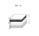
- FIG. 1C illustrates the state of the lithium battery of the disclosure after heating
- FIG. 1D illustrates the state of a lithium battery which does not include an electrode-composite separator assembly
- FIG. 1E illustrates the state of a lithium battery which does not include an electrode-composite separator assembly after bending
- FIG. 1F illustrates the state of a lithium battery which does not include an electrode-composite separator assembly after heating
- FIGS. 2 and 3 are scanning electron microscope (SEM) images of an anode-composite separator assembly of Example 1 and an anode-separator assembly of Comparative Example 2, respectively;
- FIG. 4 is a graph of open circuit voltage (Volts, V vs. Li/Li + ) and temperature (degrees Celsius, ° C.) versus thermal storage time (minutes, min) for the lithium secondary batteries of Example 7 and Comparative Example 1;
- FIGS. 5A and 5B are optical microscope images of the lithium secondary batteries of Example 7 and Comparative Example 1, respectively, after cell disassembly;
- FIG. 6 is a graph of capacity (milliAmpere-hours, mAh) versus cycle number illustrating lifetime characteristics of the lithium secondary batteries of Example 7 and Comparative Example 1;
- FIGS. 7A to 7F are graphs of voltage profile (Volts, V vs. Li/Li + ) versus capacity (milliAmpere-hours, mAh) for the lithium secondary batteries of Example 7, Examples 9 to 11, and Comparative Example 1, respectively.
- first,” “second,” “third,” etc. may be used herein to describe various elements, components, regions, layers, and/or sections, these elements, components, regions, layers, and/or sections should not be limited by these terms. These terms are only used to distinguish one element, component, region, layer, or section from another element, component, region, layer, or section. Thus, “a first element,” “component,” “region,” “layer,” or “section” discussed below could be termed a second element, component, region, layer, or section without departing from the teachings herein.
- spatially relative terms such as “beneath,” “below,” “lower,” “above,” “upper” and the like, may be used herein for ease of description to describe one element or feature's relationship to another element(s) or feature(s) as illustrated in the figures. It will be understood that the spatially relative terms are intended to encompass different orientations of the device in use or operation in addition to the orientation depicted in the figures. For example, if the device in the figures is turned over, elements described as “below” or “beneath” other elements or features would then be oriented “above” the other elements or features. Thus, the exemplary term “below” can encompass both an orientation of above and below. The device may be otherwise oriented (rotated 90 degrees or at other orientations) and the spatially relative descriptors used herein interpreted accordingly.
- “About” or “approximately” as used herein is inclusive of the stated value and means within an acceptable range of deviation for the particular value as determined by one of ordinary skill in the art, considering the measurement in question and the error associated with measurement of the particular quantity (i.e., the limitations of the measurement system). For example, “about” can mean within one or more standard deviations, or within ⁇ 30%, 20%, 10%, or 5% of the stated value.
- Exemplary embodiments are described herein with reference to cross section illustrations that are schematic illustrations of idealized embodiments. As such, variations from the shapes of the illustrations as a result, for example, of manufacturing techniques and/or tolerances, are to be expected. Thus, embodiments described herein should not be construed as limited to the particular shapes of regions as illustrated herein but are to include deviations in shapes that result, for example, from manufacturing. For example, a region illustrated or described as flat may, typically, have rough and/or nonlinear features. Moreover, sharp angles that are illustrated may be rounded. Thus, the regions illustrated in the figures are schematic in nature and their shapes are not intended to illustrate the precise shape of a region and are not intended to limit the scope of the present claims.
- an electrode-composite separator assembly for a lithium battery includes an electrode and a composite separator, wherein the composite separator includes a copolymer including a first repeating unit represented by Formula 1, a second repeating unit represented by Formula 2, and a third repeating unit represented by Formula 3, at least one selected from an inorganic particle and an organic-inorganic particle; and at least one polymer selected from a fluorinated polymer and a heat-resistant polymer; wherein Formulas 1 to 3 are
- R 1 may be a hydrogen or a C1-C5 alkyl group; and R 2 may be a C2-C20 alkyl group,
- R 5 may be a hydrogen or a C1-C5 alkyl group; and R 6 may be a methyl group,
- R 3 may be a hydrogen or a C1-C5 alkyl group
- R 4 may be a C1-C10 alkyl group.
- a lithium battery may use a polyolefin-based membrane such as a polyethylene membrane as a separator.
- a polyolefin-based membrane may not be so good for wettability of a hydrophilic electrolyte due to its hydrophobic character and the polyolefin-based membrane may have poor heat resistance.
- a separator including a binder having improved heat-resistance was developed. However, the heat-resistance of this separator may be reduced when it is exposed under high-temperature conditions at 150° C. or greater.
- the separator including a highly heat-resistant binder may have improved air-permeability, and may include undesirably large pores due to difficulty in pore size control and consequentially reduce the safety of the lithium battery.
- a lithium battery used in a flexible device may undergo repeated deformation, and the repeated deformation may cause misalignment of a separator in the battery.
- the misalignment of the separator may cause a cathode and an anode to contact one another resulting in an internal short circuit and an adverse event, and thus significantly reduce the safety of the lithium battery.
- the present disclosure provides an electrode-composite separator assembly in which electrodes and a separator are integrated together, without using a polyolefin-based membrane.
- a lithium battery with improved heat resistance, structural stability, and electrochemical characteristics may be manufactured.
- integrated is used to refer to a structure in which the electrodes and a composite separator are strongly bound to each other without an intermediate membrane therebetween.
- FIG. 1A is a schematic view illustrating a structure of an electrode-composite separator assembly according to an embodiment, and a lithium battery including the electrode-composite separator assembly.
- FIG. 1B is a schematic view illustrating a structure of an electrode-composite separator assembly, and a lithium battery including the electrode-composite separator assembly after bending.
- FIG. 1C is a schematic view illustrating a structure of an electrode-composite separator assembly, and a lithium battery including the electrode-composite separator assembly after heating.
- the lithium battery may have a structure including a cathode 13 a , an anode 12 a , and a composite separator 11 disposed between the cathode 13 a and the anode 12 a .
- the anode 12 a may comprise an anode active material layer 12 , which is disposed on an anode current collector 14 .
- the cathode 13 a may comprise a cathode active material layer 10 , which is disposed on a cathode current collector 13 .
- the composite separator 11 may be disposed directly on the anode active material layer 12 as illustrated in FIG. 1A .
- the structure of the composite separator 11 is not limited thereto.
- FIG. 1D is a schematic view illustrating a structure of an electrode assembly comprising a polyolefin separator and a lithium battery including the polyolefin separator.
- the polyolefin separator may be a polyethylene/polypropylene (PE/PP) separator, and the polyolefin separator 15 may be disposed between a cathode 13 a and an anode 12 a .
- FIG. 1E illustrates deformation caused by bending the lithium battery using a polyolefin-based separator.
- FIG. 1F illustrates deformation caused by heating the lithium battery using a polyolefin-based separator.
- misalignment of the cathode 13 a and the anode 12 a may occur due to bending (or twisting), so that the polyolefin-based separator 15 , e.g., a PE/PP separator, may be dislocated, causing the anode 12 a and the cathode 13 a to contact each other and consequently causing an internal short. Furthermore, heating may cause the PE/PP separator 15 to shrink. The shrinkage of the polyethylene/polypropylene separator 15 may also lead to an internal short circuit due to contact between the anode 12 a and the cathode 13 a , and a risk of explosion by thermal runaway.
- the polyolefin-based separator 15 e.g., a PE/PP separator
- the first repeating unit represented by Formula 1 in the copolymer of the composite separator may have low glass transition temperature, be insoluble in an electrolyte, and have improved stability against the electrolyte.
- the first repeating unit represented by Formula 1 may have a glass transition temperature of about 0° C. to about 80° C., about 10° C. to about 50° C., or about 15° C. to about 40° C.
- the first repeating unit represented by Formula 1 may be at least one selected from an ethyl (meth)acrylate unit, a propyl (meth)acrylate unit, a butyl (meth)acrylate unit, a pentyl (meth)acrylate unit, a hexyl (meth)acrylate unit, and an octyl (meth)acrylate unit.
- (meth)acrylate is inclusive of both acrylate and methacrylate.
- the second repeating unit represented by Formula 2 may have improved polymerization stability to form a target copolymer through a polymerization reaction together with the first repeating unit represented by Formula 1 and the third repeating unit represented by Formula 3.
- the second repeating unit represented by Formula 2 may be a methyl methacrylate unit or a methyl acrylate unit.
- the second repeating unit represented by Formula 2 may have a glass transition temperature of about 60° C. to about 140° C., about 80° C. to about 120° C., or about 90° C. to about 110° C.
- the amount of the second repeating unit represented by Formula 2 may be about 0.1 mole to about 1.5 moles, and in some embodiments, about 0.15 mole to about 0.5 mole, and in some other embodiments, about 0.2 moles to about 0.25 moles, based on 1 mole of the first repeating unit represented by Formula 1.
- the copolymer including the second repeating unit may have a higher glass transition temperature and improved stability, and may provide the composite separator with improved mechanical characteristics and heat resistance.
- the third repeating unit represented by Formula 3 may have a lower glass transition temperature and may have improved affinity for an electrolyte and may be more easily being dissolved in the electrolyte. Using a copolymer including the third repeating unit of Formula 3, the composite separator may have improved adhesion to the electrode.
- the third repeating unit represented by Formula 3 may have a glass transition temperature of about 0° C. to about 60° C., about 10° C. to about 50° C., or about 15° C. to about 40° C.
- the third repeating unit represented by Formula 3 may be vinyl acetate.
- the amount of the third repeating unit represented by Formula 3 may be about 0.1 mole to about 3.5 moles, and in some embodiments, about 0.5 moles to about 1.5 moles, and in some other embodiments, about 0.8 moles to about 1.25 moles, based on 1 mole of the first repeating unit represented by Formula 1.
- the composite separator may have improved wettability to electrolyte.
- the copolymer including the first repeating unit of Formula 1, the second repeating unit of Formula 2, and the third repeating unit of Formula 3 may provide improved affinity to an electrolyte and improved thermal stability.
- the copolymer of the composite separator may have improved wettability to the electrolyte and improved lithium ionic conductivity, compared to a fluorinated polymer such as polyvinylidene fluoride (PVDF), and thus may provide improved lithium ion conductivity across the composite separator.
- PVDF polyvinylidene fluoride
- the copolymer of the composite separator may be a block copolymer, a graft copolymer, a random copolymer, or an alternating copolymer.
- the copolymer of the composite separator may be a block copolymer.
- the composite separator may have improved electrochemical and mechanical characteristics.
- the copolymer of the composite separator may have a weight average molecular weight of about 300,000 Daltons to about 1,200,000 Daltons, about 400,000 Daltons to about 1,000,000 Daltons, or about 500,000 Daltons to about 700,000 Daltons.
- the composite separator may have improved mechanical characteristics, e.g., greater modulus, and improved thermal stability.
- the copolymer of the composite separator may be a copolymer represented by Formula 4a or 4b.
- n, m, and p are mole fractions of the first to third repeating units, respectively, and may be each independently about 0.01 to about 0.99, wherein the sum of n, m. and p may be 1.
- the copolymer represented by Formula 4a or 4b may have a viscosity of about 200 centipoise (cP) to about 1,200 cP, about 300 cP to about 1,000 cP, or about 400 cP to about 800 cP at 25° C., when measured as a 10 weight percent (wt %) solution thereof in acetone.
- the copolymer represented by Formula 4a (wherein n is 0.4, m is 0.1, and p is 0.5) may have a glass transition temperature of about 36° C. to about 38° C.
- the composite separator may include, in addition to the copolymer, at least one selected from an inorganic particle and organic-inorganic particle, and at least one polymer selected from a fluorinated polymer and a heat-resistant polymer.
- the at least one selected from an inorganic particle and an organic-inorganic particle may be at least one selected from Al 2 O 3 , SiO 2 , B 2 O 3 , Ga 2 O 3 , TiO 2 , SnO 2 , BaTiO 3 , Pb(Zr a Ti 1 ⁇ a )O 3 wherein 0 ⁇ a ⁇ 1, Pb 1 ⁇ x La x Zr y O 3 wherein 0 ⁇ x ⁇ 1, and 0 ⁇ y ⁇ 1, Pb(Mg 3 Nb 2/3 ) 3 , PbTiO 3 , HfO 2 , SrTiO 3 , CeO 2 , MgO, NiO, CaO, ZnO, Y 2 O 3 , TiO 2 , SiC, ZrO 2 , a borosilicate, BaSO 4 , a nanoclay, fumed silica, fumed alumina, graphite oxide, graphene oxide, and a metal-organic framework.
- the metal-organic framework may be in the form of organic-inorganic particles and may be a porous crystalline compound in which a Group 2 to Group 15 metal ion, which may be in the form of a cluster of Group 2 to Group 15 metal ions, is chemically bonded with an organic ligand.
- the organic ligand refers to an organic group that may form an organic bond such as coordinate bond, ionic bond, or covalent bond with the metal ion.
- an organic group having at least two binding sites for such metal ions as described above may form a stable structure through binding with the metal ions.
- the Group 2 to Group 5 metal ion may be at least one selected from cobalt (Co), nickel (Ni), molybdenum (Mo), tungsten (W), ruthenium (Ru), osmium (Os), cadmium (Cd), beryllium (Be), calcium (Ca), barium (Ba), strontium (Sr), iron (Fe), manganese (Mn), chromium (Cr), vanadium (V), aluminum (Al), titanium (Ti), zirconium (Zr), copper (Cu), zinc (Zn), magnesium (Mg), hafnium (Hf), niobium (Nb), tantalum (Ta), rhenium (Re), rhodium (Rh), iridium (Ir), palladium (Pd), platinum (Pt), silver (Ag), scandium (Sc), yttrium (Y), indium (In), thallium (TI), silicon (Si), germanium (Ge), t
- the organic ligand may be a group derived from at least one compound selected from an aromatic dicarboxylic acid, an aromatic tricarboxylic acid, an imidazole, a tetrazole, 1,2,3-triazole, 1,2,4-triazole, pyrazole, an aromatic sulfonic acid, an aromatic phosphoric acid, an aromatic sulfinic acid, an aromatic phosphinic acid, a bipyridine, and a compound having at least one functional group selected from an amino group, an imino group, an amide group, a dithio carboxylic acid group (—CS 2 H), a dithio carboxylate group (—CS 2 ⁇ ), a pyridine group, and a pyrazine group.
- Non-limiting examples of the aromatic dicarboxylic acid and the aromatic tricarboxylic acid are benzene dicarboxylic acid, benzene tricarboxylic acid, biphenyl dicarboxylic acid, and terphenyl-dicarboxylic acid.
- the organic ligand may be a group including at least one structure selected from those represented by Formula 5.
- the metal-organic framework may be, for example, at least one selected from Ti 8 O 8 (OH) 4 [O 2 C—C 6 H 4 —CO 2 ] 6 , Cu(bpy)(H 2 O) 2 (BF 4 ) 2 (bpy) wherein bpy is 4,4′-bipyridine, Zn 4 O(O 2 C—C 6 H 4 —CO 2 ) 3 (Zn-terephthalic acid-MOF, Zn-MOF), and Al(OH)(O 2 C—C 6 H 4 —CO 2 ).
- the cage-structured silsesquioxane may be a polyhedral oligomeric silsesquioxane (POSS).
- the number of silicon atoms in the POSS may be about 8 or less, for example, 6 or 8.
- the cage-structured silsesquioxane may be a compound represented by Formula 6.
- R 1 , R 2 , and R 3 may each independently be a hydrogen, a substituted or unsubstituted C1-C30 alkyl group, a substituted or unsubstituted C1-C30 alkoxy group, a substituted or unsubstituted C2-C30 alkenyl group, a substituted or unsubstituted C2-C30 alkynyl group, a substituted or unsubstituted C6-C30 aryl group, a substituted or unsubstituted C6-C30 aryloxy group, a substituted or unsubstituted C2-C30 heteroaryl group, a substituted or unsubstituted C4-C30 carbocyclic group, or a silicon-containing functional group.
- the cage-structured silsesquioxane may be at least one selected from a compound represented by Formula 7 and a compound represented by Formula 8.
- R 1 to R 8 may each independently be a hydrogen, a substituted or unsubstituted C1-C30 alkyl group, a substituted or unsubstituted C1-C30 alkoxy group, a substituted or unsubstituted C2-C30 alkenyl group, a substituted or unsubstituted C2-C30 alkynyl group, a substituted or unsubstituted C6-C30 aryl group, a substituted or unsubstituted C6-C30 aryloxy group, a substituted or unsubstituted C2-C30 heteroaryl group, a substituted or unsubstituted C4-C30 carbocyclic group, or a silicon-containing functional group.
- R 1 to R 6 may each independently be a hydrogen, a substituted or unsubstituted C1-C30 alkyl group, a substituted or unsubstituted C1-C30 alkoxy group, a substituted or unsubstituted C2-C30 alkenyl group, a substituted or unsubstituted C2-C30 alkynyl group, a substituted or unsubstituted C6-C30 aryl group, a substituted or unsubstituted C6-C30 aryloxy group, a substituted or unsubstituted C2-C30 heteroaryl group, a substituted or unsubstituted C4-C30 carbocyclic group, or a silicon-containing functional group.
- R 1 to R 8 in Formula 7 and R 1 to R 6 in Formula 8 may be an isobutyl group.
- the cage-structured silsesquioxane may be octaisobutyl-t8-silsesquioxane.
- the inorganic particle of the composite separator may be Al 2 O 3 , which is not reactive with lithium.
- the at least one selected from an inorganic particle and an organic-inorganic particle may have an average particle diameter of about 1 ⁇ m or less, and in some embodiments, about 500 nm or less, and in some other embodiments, about 100 nm or less.
- the at least one selected from an inorganic particle and an organic-inorganic particle may have a particle diameter of about 1 nm to about 1000 nm, about 1 nm to about 100 nm, and in some embodiments, about 10 nm to about 100 nm, and in some other embodiments, about 30 nm to about 70 nm.
- the composite separator may have suitable film formability and mechanical properties without deterioration in ionic conductivity.
- the heat-resistant polymer of the composite separator may be a polymer with high thermal stability, for example, at least one selected from an aromatic polyester, polyimide, polyethersulfone (PES), polyvinylidene fluoride, polyamide, poly(meta-phenylene isophthalamide), polysulfone (PSU), polyetherketone, polyethylene terephthalate, polytrimethylene terephthalate, polyethylene naphthalate, polyphosphazene (e.g., poly(diphenoxy phosphazene or poly ⁇ bis[2-(2-methoxyethoxy)phosphazene] ⁇ ), polyurethane copolymer, polyurethane, polyether urethane, cellulose acetate, cellulose acetate butyrate, cellulose acetate propionate, polyestersulfone, polyetherimide (PEI), polycarbonate, polyphenylene sulfide (PPS), polyacrylate, and polytetrafluoroethylene.
- PES
- the fluorinated polymer of the composite separator may be at least one selected from polyvinylidene fluoride, a vinylidene fluoride-hexafluoropropylene copolymer, a vinylidene fluoride-trichloroethylene copolymer, and a vinylidene fluoride-chlorotrifluoroethylene copolymer.
- the fluorinated polymer may include, for example, a high-viscosity high-molecular weight fluorinated polymer and a high-elasticity low-viscosity fluorinated polymer.
- the high-viscosity high-molecular weight fluorinated polymer refers to a fluorinated polymer having a viscosity of about 3,000 to about 5,000 cP (when determined in N-methyl pyrrolidone (NMP) in an amount of 2 to 5 wt %) and a weight average molecular weight of about 1,000,000 to about 1,200,000 Daltons (Da), and may be, for example, PVDF 5130 (Solef 5130, available from Solvay America, Inc.).
- the high-elasticity low-viscosity fluorinated polymer refers to a polymer having a viscosity of about 2,000 to about 4,000 cP (when determined in acetone in an amount of 2 to 5 wt %) and a tensile modulus (Young's modulus) of about 1,300 to about 2,000 megaPascals (MPa), and may be, for example, PVDF 6020 (Solef 6020, available from Solvay America, Inc.).
- the tensile modulus may determined according to ASTM D882.
- the amount of the high-viscosity high-molecular weight fluorinated polymer may be from about 20 to about 80 parts by weight, about 30 to about 70 parts by weight, or about 40 to about 60 parts by weight, based on 100 parts by weight of a total weight of the fluorinated polymer.
- the composite separator may have improved mechanical adhesion characteristics
- the amount of the at least one of an inorganic particle and an organic-inorganic particle may be from about 500 parts to about 5,000 parts by weight, and in some embodiments, about 1,000 parts to about 3,000 parts by weight, or about 1,500 to about 2,500 parts by weight, based on 100 parts by weight of the total weight of the copolymer and the at least one selected from a fluorinated polymer and a heat-resistant polymer.
- the composite separator may have improved flexibility without breakage.
- a weight ratio of the copolymer to the at least one selected from a fluorinated polymer and a heat-resistant polymer may be from about 1:9 to about 9:1, or from about 1:6 to about 6:1, or from about 1:2 to about 2:1, and in some embodiments, about 7:3.
- a lithium battery including the composite separator may have improved capacity characteristics.
- the composite separator may have a thickness of about 5 micrometers ( ⁇ m) to about 60 ⁇ m, about 10 ⁇ m to about 45 ⁇ m, or about 15 ⁇ m to about 30 ⁇ m. When the thickness of the composite separator is within any of these ranges, a lithium battery including the composite separator may have improved electrochemical characteristics without reduction in safety.
- the composite separator of the electrode-composite separator assembly may include Al 2 O 3 , a copolymer represented by Formula 4a, and polyvinylidene fluoride.
- n, m, and p which indicate mole fractions of the first, second, and third repeating units, respectively, may each independently be about 0.01 to about 0.99, about 0.05 to about 0.9, or about 0.1 to about 0.5, and may be about 1 in total.
- n may be 0.4
- m may be 0.1
- p may be 0.5.
- the electrode-composite separator assembly may have improved thermal stability.
- the electrode-composite separator assembly may have a thermal shrinkage ratio of less than about 1% both in vertical and horizontal directions after storage at 150° C. for 1 hour.
- the composite separator including inorganic particles (for example, Al 2 O 3 ) with suitable heat resistance may have a reduced likelihood of undergoing thermal shrinkage, and thus have a lower risk of internal short circuit between the electrodes.
- the electrode-composite separator assembly may have ensured structural stability even after repeated bending or deformation since misalignment of the anode and the cathode to the composite separator does not occur to cause direct contact between the anode and the cathode.
- the composite separator of the electrode-composite separator assembly may have a porosity of about 30% to about 70%, about 40% to about 60%, or about 45% to about 55%. When the composite separator has a porosity within this range, mobility of lithium ions across the composite separator may be improved.
- the electrode-composite separator assembly may be manufactured by integrating a composite separator including i) the copolymer including a first repeating unit of Formula 1, a second repeating unit of Formula 2, and a third repeating unit of Formula 3, ii) the fluorinated polymer, and iii) the at least one selected from an inorganic particle and an organic-inorganic particle with at least one selected from a cathode and an anode.
- the integrating of the composite separator with the at least one selected from cathode and anode may include directly coating a composite separator composition on the electrode and drying the resulting structure to form the composite separator.
- the integrating of the composite separator with the at least one selected from the cathode and the anode may include coating a composite separator composition on a substrate and drying the resulting structure to form the composite separator, then detaching the composite separator from the substrate, and disposing it between the cathode and anode, thereby manufacturing a target electrode-composite separator assembly.
- the composite separator composition may be coated on the anode.
- An anode may have a larger area than a cathode. Therefore, the composite separator may be prepared to have an equal or larger size than that of the anode.
- the composite separator may have improved affinity to the electrolyte, provide improved electrolyte impregnating ability, improved electrolyte leakage preventing ability, and improved lithium ion conductivity.
- the electrode-composite separator assembly may further include an additional separator.
- the additional separator may be disposed on the composite separator.
- This additional separator may be any suitable separator for a lithium battery.
- the separator may be a polyolefin-based porous membrane or a non-woven fabric, but is not limited thereto.
- the polyolefin-based porous membrane may be a polymer membrane including at least one selected from a polyolefin polymer, for example, a polyethylene such as a high-density polyethylene, a low-density polyethylene, a linear low-density polyethylene, a ultra-high molecular weight polyethylene, a polypropylene, a polybutylene, and a polypentene.
- a polyethylene such as a high-density polyethylene, a low-density polyethylene, a linear low-density polyethylene, a ultra-high molecular weight polyethylene, a polypropylene, a polybutylene, and a polypentene.
- the non-woven fabric may be a polyolefin non-woven fabric, or a non-woven fabric including a polymer, for example, at least one selected from polyethylene terephthalate, polybutylene terephthalate, polyester, polyacetal, polyamide, polycarbonate, polyimide, polyetherether ketone, polyethersulfone, polyphenylene oxide, polyphenylene sulfide, and polyethylene naphthalene.
- a combination comprising at least two of the foregoing may be used.
- the non-woven fabric may be a spun-bond non-woven fabric or a meltblown non-woven fabric comprising long fibers, e.g., fibers having a length of about 1 ⁇ m to 1 meter, or about 100 ⁇ m to about 10 centimeter (cm).
- the separator may have any suitable thickness, and may have a thickness of, for example, about 1 ⁇ m to about 100 ⁇ m, about 5 ⁇ m to about 50 ⁇ m, or about 10 ⁇ m to about 40 ⁇ m.
- the separator may have any suitable pore size, and may have a pore size of, for example, about 1 nm to about 500 nm, about 1 nm to about 200 nm, or about 1 nm to about 100 nm, and any suitable porosity, for example a porosity of 5% to about 99%, 10% to about 95%, or 20% to about 80%.
- the composite separator of the electrode-composite separator assembly may further include a binder, which may be used in manufacturing a cathode and/or an anode.
- the binder may be at least one selected from styrene butadiene rubber, carboxymethyl cellulose (CMC), polyvinyl alcohol, starch, hydroxypropyl cellulose, reproduced cellulose, polyvinylpyrrolidone, polytetrafluoroethylene, polyethylene, polypropylene, ethylene propylene diene terpolymer (EPDM), sulfonated EPDM, and fluorocarbon rubber.
- the amount of the binder may be in a range of about 0.1 part to about 300 parts by weight, 0.5 part to about 100 parts by weight, or 1 part to about 50 parts by weight, based on 100 parts by weight of a total weight of the copolymer and the at least one of a fluorinated polymer and a heat-resistant polymer.
- At least one of an inorganic particle and an organic-inorganic particle, a fluorinated polymer, and a copolymer including a first repeating unit represented by Formula 1, a second repeating unit represented by Formula 2, and a third repeating unit represented by Formula 3 are mixed with a solvent to obtain a composite separator composition.
- the composite separator may be coated on an electrode and then dried to form the electrode-composite separator assembly.
- the coating of the composite separator composition may be performed using spin coating, roll coating, curtain coating, extrusion, screen printing, inkjet printing, a doctor blade, or the like.
- the drying may be performed at a temperature of about 25° C. to about 130° C.
- the drying may be performed under vacuum conditions.
- the solvent may be any suitable organic solvent available in the art.
- the organic solvent may be at least one selected from tetrahydrofuran, N-methylpyrrolidone, acetonitrile, benzonitrile, 2-methyl tetrahydrofuran, ⁇ -butyrolactone, dioxolane, N, N-dimethylformamide, N, N-dimethyl acetamide, dimethyl sulfoxide, dioxane, 1,2-dimethoxyethane, 1,2-diethoxyethane, sulfolane, dichloroethane, chlorobenzene, nitrobenzene, diethyleneglycol, and dimethyl ether.
- the amount of the solvent may be about 50 parts to about 10,000 parts by weight, about 100 parts to about 5,000 parts by weight, or about 300 parts to about 3,000 parts by weight, based on 100 parts by weight of a total weight of the at least one selected from an inorganic particle and an organic-inorganic particle, the at least one polymer selected from a fluorinated polymer and a heat-resistant polymer, and the copolymer.
- the composite separator composition may be prepared by mixing all the ingredients at the same time.
- the composite separator composition may be prepared by mixing the at least one selected from an inorganic particle and an organic-inorganic particle with a solvent and a dispersing agent to obtain a dispersion of the at least one selected from an inorganic particle and an organic-inorganic particle, and mixing the dispersion with a fluorinated polymer and a copolymer as described above.
- the fluorinated polymer and the copolymer may be each separately dispersed or dissolved in a solvent to prepare a dispersion or solution thereof.
- the dispersion of the at least one selected from an inorganic particle and an organic-inorganic particle may be prepared by milling.
- the milling may provide improved control of the average particle diameter of the inorganic particle and the organic-inorganic particle and provide an average particle diameter of about 0.5 ⁇ m or less, e.g., about 0.001 ⁇ m to about 0.2 ⁇ m, about 0.005 ⁇ m to about 0.1 ⁇ m, or about 0.05 ⁇ m to about 0.1 ⁇ m so that the composite separator composition may have a uniform composition.
- the composite separator may have improved mechanical characteristics.
- a dispersing agent may be used, and the dispersing agent may be a compound or polymer including a polar group, such as a carboxyl group, or a hydroxyl group.
- the dispersing agent may be an acid-containing compound such as a phosphoric acid ester; an acid group-containing copolymerization product; a hydroxyl group-containing polycarboxylic acid ester, polysiloxane, a salt of a long-chain polyaminoamide, and an acid ester. Any suitable dispersing agent may be used.
- the dispersing agent may be at least one selected from Triton X-100, acetic acid, cetyltrimethyl ammonium bromide (CTAB), isopropyltris(N-aminoethylaminoethyl)titanate (INAAT, available from Ajimoto Fine-Techno Co. Inc.), 3-aminopropyltriethoxy-silane (APTS, available from Aldrich), polyvinyl pyrrolidone (PVP), or poly(4-vinylphenol).
- CTAB cetyltrimethyl ammonium bromide
- INAAT isopropyltris(N-aminoethylaminoethyl)titanate
- APTS 3-aminopropyltriethoxy-silane
- PVP polyvinyl pyrrolidone
- poly(4-vinylphenol) poly(4-vinylphenol
- a lithium battery includes the electrode-composite separator assembly.
- the electrode of the electrode-composite separator assembly may be an anode.
- the lithium battery may further include a solid electrolyte including at least one selected from an inorganic particle and an organic-inorganic particle, and a lithium ionic conductor.
- the solid electrolyte may be between the composite separator and a cathode.
- the lithium ionic conductor may be at least one selected from Li 3 N, a lithium super ionic conductor, Li 3y PO 4 ⁇ x N x wherein 0 ⁇ y ⁇ 3 and 0 ⁇ x ⁇ 4, Li 3.25 Ge 0.25 P 0.75 S 4 , Li 2 S, Li 2 S—P 2 S 5 , Li 2 S—SiS 2 , Li 2 S—GeS 2 , Li 2 S—B 2 S 5 , Li 2 S—Al 2 S 5 , Li 2 O—Al 2 O 3 —TiO 2 —P 2 O 5 , lithium lanthanum titanate Li 0.34 La 0.51 TiO 2.94 , lithium titanium aluminum phosphate, and Li 1+x Ti 2 ⁇ x Al(PO 4 ) 3 wherein 0 ⁇ x ⁇ 0.4.
- the lithium battery may further include a liquid electrolyte.
- the copolymer of the composite separator may be insoluble in the liquid electrolyte. “Insoluble” in the liquid electrolyte means that the maximum solubility of the copolymer in the liquid electrolyte is less than 5 wt %, less than 1 wt %, less than 0.1 wt %, or less than 0.01 wt %, based on the total weight of the liquid electrolyte. An embodiment in which a solubility of the copolymer in the liquid electrolyte is less than 1 wt % is mentioned.
- the lithium battery may include a gel electrolyte, and if desired the gel electrolyte may be provided instead of the solid electrolyte. In some other embodiments, the lithium battery may include both a solid electrolyte and a gel electrolyte.
- the gel electrolyte may be any suitable electrolyte in gel form.
- the gel electrolyte may include a polymer and a polymer ionic liquid.
- the poly mer may be a solid graft (block) copolymer electrolyte.
- the solid electrolyte may be, for example, an organic solid electrolyte or an inorganic solid electrolyte.
- organic solid electrolyte include those comprising polyethylene, a polyethylene derivative, polyethylene oxide, a polyethylene oxide derivative, polypropylene oxide, a polypropylene oxide derivative, a phosphoric acid ester polymer, polyester sulfide, polyvinyl alcohol, polyvinylidene fluoride, and polymers including ionic dissociative groups. A combination comprising at least two of the foregoing may be used.
- Non-limiting examples of the inorganic solid electrolyte are Li 3 N, LiI, Li 5 NI 2 , Li 3 N—LiI—LiOH, Li 2 SiS 3 , Li 4 SiO 4 , Li 4 SiO 4 —LiI—LiOH, Li 3 PO 4 —Li 2 S—SiS 2 , Cu 3 N, LiPON, Li 2 S.GeS 2 .
- Ga 2 S 3 Li 2 O.11Al 2 O 3 , (Na,Li) 1+x Ti 2 ⁇ x Al x (PO 4 ) 3 wherein 0.1 ⁇ 0.9, Li 1+x Hf 2 ⁇ x Al x (PO 4 ) 3 wherein Na 3 Zr 2 Si 2 PO 12 , Li 3 Zr 2 Si 2 PO 12 , Na 5 ZrP 3 O 12 , Na 5 TiP 3 O 12 , Na 3 Fe 2 P 3 O 12 , Na 4 NbP 3 O 12 , Na-Silicates, Li 0.3 La 0.5 TiO 3 , Na 5 MSi 4 O 12 wherein M is a rare earth element, such as Nd, Gd, Dy, or the like, Li 5 ZrP 3 O 12 , Li 5 TiP 3 O 12 , Li 3 Fe 2 P 3 O 12 , Li 4 NbP 3 O 12 , Li 1+x (M,Al,Ga) x (Ge 1 ⁇ y Ti y ) 2 ⁇ x (PO 4 ) 3 wherein
- the cathode of the lithium battery may be a porous cathode.
- the porous cathode may be a cathode including pores, or any cathode that allows permeation of liquid electrolyte thereinto by capillary action.
- the porous cathode may be a cathode that may be obtained by coating a cathode active material composition including a cathode active material, a conducting agent, a binder, and a solvent, and drying the resulting structure.
- the resulting cathode may include pores among particles of the cathode active material.
- the porous cathode may be impregnated with liquid electrolyte.
- the cathode may further include a liquid electrolyte, a gel electrolyte, a solid electrolyte, or the like.
- the liquid electrolyte, the gel electrolyte, and the solid electrolyte may be any suitable electrolyte available for lithium batteries that does not react with the cathode active material, and thus prevent deterioration of the cathode active material during charging and discharging.
- a cathode active material for the cathode may include at least one selected from lithium cobalt oxide, lithium nickel cobalt manganese oxide, lithium nickel cobalt aluminum oxide, lithium iron phosphate, and lithium manganese oxide, but is not limited thereto. Any suitable cathode active material may be used.
- the cathode active material may comprise at least one compound selected from compounds represented by the following formulas: Li a A 1 ⁇ b B′ b D 2 wherein 0.90 ⁇ a ⁇ 1.8 and 0 ⁇ b ⁇ 0.5; Li a E 1 ⁇ b B′ b O 2 ⁇ c D c wherein 0.90 ⁇ a ⁇ 1.8, 0 ⁇ b ⁇ 0.5, and 0 ⁇ c ⁇ 0.05; Li E 2 ⁇ b B′ b O 4 ⁇ c D c wherein 0 ⁇ b ⁇ 0.5, and 0 ⁇ c ⁇ 0.05; Li a Ni 1 ⁇ b ⁇ c Co b B′ c D, wherein 0.90 ⁇ a ⁇ 1.8, 0 ⁇ b ⁇ 0.5, 0 ⁇ c ⁇ 0.05, and 0 ⁇ 2; Li a Ni 1 ⁇ b ⁇ c Co b B′ c O 2 ⁇ a F′, wherein 0.90 ⁇ a ⁇ 1.8, 0 ⁇ b ⁇ 0.5, 0 ⁇ c ⁇ 0.05, and 0 ⁇ 2; Li a Ni 1 ⁇ b ⁇ c Mn b B′ c D ⁇ wherein 0.90 ⁇ a, Li
- A is at least one selected from nickel (Ni), cobalt (Co), an d manganese (Mn);
- B′ is at least one selected from aluminum (Al), nickel (Ni), cobalt (Co), manganese (Mn), chromium (Cr), iron (Fe), magnesium (Mg), strontium (Sr), vanadium (V), and a rare earth element;
- D is at least one selected from oxygen (O), fluorine (F), sulfur (S), and phosphorus (P);
- E is at least one selected from cobalt (Co), and manganese (Mn);
- F′ is at least one selected from fluorine (F), sulfur (S), and phosphorus (P);
- G is at least one selected from aluminum (Al), chromium (Cr), manganese (Mn), iron (Fe), magnesium (Mg), lanthanum (La), cerium (Ce), strontium (Sr), and vanadium (V);
- Q is at least one selected from
- the cathode active material may be at least one compound represented by Formula 9, Formula 10, and Formula 11.
- M may be Mn, Fe, Co, or Ni.
- the cathode of the lithium battery may be manufactured as follows.
- a cathode active material, a binder, and a solvent are mixed to prepare a cathode active material layer composition.
- a conducting agent may be further added into the cathode active material layer composition.
- the cathode active material layer composition is directly coated on a metallic current collector and dried to prepare a cathode.
- the cathode active material layer composition may be cast on a separate support to form a cathode active material film, which may then be separated from the support and then laminated on a metallic current collector to prepare a cathode plate.
- the binder is a composition that contributes binding with an active material and a conductive material and binding with a current collector, and an amount of the binder added may be from about 1 part to about 100 parts by weight, about 1 part to about 50 parts by weight, or about 1 part to about 30 parts by weight based on 100 parts by weight of the total weight of the cathode active material.
- Non-limiting examples of the binder include at least one selected from polyvinylidene fluoride (PVDF), polyvinyl alcohol, carboxymethylcellulose (CMC), starch, hydroxypropylcellulose, cellulose, polyvinylpyrrolidone, polytetrafluoroethylene, polyethylene, polypropylene, ethylene-propylene-diene terpolymer (EPDM), sulfonated EPDM, styrene butadiene rubber, and a fluorinated rubber.
- PVDF polyvinylidene fluoride
- CMC carboxymethylcellulose
- EPDM ethylene-propylene-diene terpolymer
- EPDM ethylene-propylene-diene terpolymer
- sulfonated EPDM styrene butadiene rubber
- a fluorinated rubber a fluorinated rubber
- the amount of the binder may be about 1 part to about 20 parts by weight, about 2 parts to about 5 parts by weight, or about 2 parts to about 3 parts by weight, based on 100 parts by weight of the total weight of the cathode active material. When the amount of the binder is within this range, a binding force of the active material layer to the current collector may be satisfactory.
- the conducting agent may be any suitable material, e.g., a material that does not cause an adverse chemical change in the lithium battery and provides suitable conductivity.
- suitable material e.g., a material that does not cause an adverse chemical change in the lithium battery and provides suitable conductivity.
- Non-limiting examples of the conducting agent include graphite, such as natural graphite or artificial graphite; a carbonaceous material such as carbon black, acetylene black, Ketjen black, channel black, furnace black, lamp black, or summer black; a conductive fiber, such as carbon fiber or metal fiber; carbon fluoride; a metal powder, such as aluminum or nickel powder; a conductive whisker, such as zinc oxide or potassium titanate; a conductive metal oxide, such as a titanium oxide; and a conductive polymer, such as a polyphenylene derivative.
- graphite such as natural graphite or artificial graphite
- a carbonaceous material such as carbon black, acetylene black, Ketjen black, channel black
- the amount of the conducting agent may be from about 1 part to about 10 parts by weight, from about 2 parts to about 5 parts by weight, or about 2 parts to about 3 parts by weight, based on 100 parts by weight of the total weight of the cathode active material. When the amount of the conducting agent is within any of these ranges, the final cathode may have good conductivity characteristics.
- a non-limiting example of the solvent is N-methylpyrrolidone.
- the amount of the solvent may be from about 50 parts to about 5,000 parts by weight, about 100 parts to about 2,000 parts by weight, or about 200 parts to about 1,000 parts by weight, based on 100 parts by weight of the cathode active material. When the amount of the solvent is within this range, a process for forming the active material layer may be easily carried out.
- the anode of the lithium battery may be manufactured in a substantially same manner as in the manufacture of the cathode, except for using an anode active material instead of the cathode active material.
- the anode active material may comprise at least one selected from a carbonaceous material, silicon, a silicon oxide, a silicon-based alloy, a silicon-carbonaceous material composite, tin, a tin-based alloy, a tin-carbon composite, and a metal oxide.
- the carbonaceous material may comprise a crystalline carbon or an amorphous carbon.
- the crystalline carbon may be graphite, such as a natural graphite or an artificial graphite, and the graphite may be in at least one selected from a plate, flake, spherical, and fibrous form.
- the amorphous carbon may be soft carbon (carbon sintered at low temperatures), hard carbon, meso-phase pitch carbonization product, sintered coke, graphene, carbon black, fullerene soot, carbon nanotubes, and carbon fiber. Any appropriate anode active material may be used.
- the anode active material may be at least one selected from Si, SiO x where 0 ⁇ x ⁇ 2, for example, 0.5 ⁇ x ⁇ 1.5, Sn, SnO 2 , and a silicon-containing metal alloy.
- a metal that is alloyable with silicon may be at least one selected from Al, Sn, Ag, Fe, Bi, Mg, Zn, In, Ge, Pb, and Ti.
- the anode active material may include a metal and/or metalloid that is alloyable with lithium, an alloy thereof, or an oxide thereof.
- the metal and/or metalloid alloyable with lithium, the alloy thereof, or the oxide thereof are at least one selected from Si, Sn, Al, Ge, Pb, Bi, Sb, a Si—Y′ alloy where Y′ is an alkali metal, an alkaline earth metal, a Group 13-16 element, a transition metal, and a rare earth element, except for Si, a Sn—Y′′ alloy where Y′′ is at least one selected from an alkali metal, an alkaline earth metal, a Group 13-16 element, a transition metal, and a rare earth element except for Sn, and MnO x where 0 ⁇ x ⁇ 2.
- Y′ and Y′′ may each independently be at least one selected from magnesium (Mg), calcium (Ca), strontium (Sr), barium (Ba), radium (Ra), scandium (Sc), yttrium (Y), titanium (Ti), zirconium (Zr), hafnium (Hf), rutherfordium (Rf), vanadium (V), niobium (Nb), tantalum (Ta), dubnium (Db), chromium (Cr), molybdenum (Mo), tungsten (W), seaborgium (Sg), technetium (Tc), rhenium (Re), bohrium (Bh), iron (Fe), lead (Pb), ruthenium (Ru), osmium (Os), hassium (Hs), rhodium (Rh), iridium (Ir), palladium (Pd), platinum (Pt), copper (Cu), silver (Ag), gold (Au), zinc (Zn), c
- a composite separator composition e.g., a composition comprising a fluorinated polymer, at least one selected from an inorganic particle and an organic-inorganic particle, and a copolymer including a first repeating unit of Formula 1, a second repeating unit of Formula 2, and a third repeating unit of Formula 3, may then be coated on the anode and dried to manufacture an anode-composite separator assembly.
- the anode-composite separator assembly may be assembled with the cathode, followed by adding an electrolyte, thereby manufacturing the lithium battery.
- the lithium battery may further include an additional separator.
- the electrolyte may include a lithium salt and an organic solvent.
- the organic solvent are at least one selected from a carbonate compound, a glyme compound, and a dioxolane compound.
- the carbonate compound may be at least one selected from ethylene carbonate, propylene carbonate, dimethyl carbonate, fluoroethylene carbonate, diethyl carbonate, and ethylmethyl carbonate.
- the glyme compound may be, for example, at least one selected from poly(ethylene glycol)dimethyl ether, tetra(ethylene glycol)dimethyl ether, tri(ethylene glycol)dimethyl ether, poly(ethylene glycol)dilaurate, poly(ethylene glycol) monoacylate, and poly(ethylene glycol)diacrylate.
- the dioxolane compound may be, for example, at least one selected from 3-dioxolane, 4,5-diethyl-1,3-dioxolane, 4,5-dimethyl-1,3-dioxolane, 4-methyl-1,3-dioxolane, and 4-ethyl-1,3-dioxolane.
- the organic solvent may be 2,2-dimethoxy-2-phenyl acetophenone, 1,2-dimethoxyethane (DME), 1,2-diethoxy ethane, tetrahydrofuran, gamma-butyrolactone, and 1,1,2,2-tetrafluoroethyl 2,2,3,3-tetrafluoropropyl ether.
- the organic solvent of the electrolyte may include at least one selected from propylene carbonate, ethylene carbonate, fluoroethylene carbonate, butylene carbonate, dimethyl carbonate, diethyl carbonate, methylethyl carbonate, methylpropyl carbonate, ethylpropyl carbonate, methylisopropyl carbonate, dipropyl carbonate, dibutyl carbonate, chloroethylene carbonate, benzonitrile, acetonitrile, tetrahydrofuran, 2-methyltetrahydrofuran, ⁇ -butyrolactone, dioxolane, 4-methyl-1,3-dioxolane, N,N-dimethyl formamide, N,N-dimethyl acetamide, dimethylsulfoxide, dioxane, sulforane, dichloroethane, chlorobenzene, nitrobenzene, diethylene glycol, dimethyl ether, 1,1,2,2-tetrafluoroe, but
- the lithium salt in the electrolyte may be at least one selected from LiSCN, LiN(CN) 2 , LiCIO 4 , LiBF 4 , LiAsF 6 , LiPF 6 , LiCF 3 SO 3 , LiC(CF 3 SO 2 ) 3 , LiN(SO 2 C 2 F 5 ) 2 , LiN(SO 2 CF 3 ) 2 , LiN(SO 2 F) 2 , LiAlO 2 , LiAlCl 4 , LiCl, LiI, LiSbF 6 , LiPF 3 (CF 2 CF 3 ) 3 , LiPF 3 (CF 3 ) 3 , and LiB(C 2 O 4 ) 2 .
- the amount of the lithium salt in the liquid electrolyte may be about 0.01 molar (M) to about 5 M, about 0.01 M to about 2 M, or about 0.1 M to about 1 M.
- the electrode-composite separator assembly of the lithium battery may have improved thermal and mechanical stability.
- the electrode-composite separator assembly may also have improved lithium ionic conductivity and improved wettability to the electrolyte, and thus the lithium battery may have improved electrochemical performance.
- the lithium battery may be manufactured without using a polyolefin-based separator, the lithium battery may be manufactured in any of a variety of forms, and may have improved structural stability against repeated bending or heating.
- the lithium battery according to an embodiment may prevent shrinkage of the composite separator caused by exposure to high-temperature molding or heat, and may suppress misalignment of the electrodes caused by cell bending or twisting. Thus, battery performance degradation caused from such misalignment and a thermal runaway caused by an internal short circuit may be prevented.
- the lithium battery may have improved capacity and improved lifetime characteristics, and thus may be used in a battery cell for use as a power source of a small device, and may also be used as a unit battery of a medium-large size battery pack or battery module that include a plurality of battery cells for use as a power source of a medium-large size device.
- the lithium battery may have improved voltage characteristics, improved capacity, and improved energy density, and thus may be used in mobile phones, laptop computers, storage batteries for power generating units using wind power or sunlight, electric vehicles, uninterruptable power supplies (UPS), household storage batteries, and the like.
- Examples of applications include electric vehicles (EVs), including hybrid electric vehicles (HEVs) and plug-in hybrid electric vehicles (PHEVs); electric two-wheeled vehicles, including E-bikes and E-scooters; power tools; power storage devices; and the like, but are not limited thereto.
- EVs electric vehicles
- HEVs hybrid electric vehicles
- PHEVs plug-in hybrid electric vehicles
- electric two-wheeled vehicles including E-bikes and E-scooters
- power tools power storage devices; and the like, but are not limited thereto.
- alkyl refers to a completely saturated branched or unbranched (or straight-chained or linear) hydrocarbon group.
- Non-limiting examples of the “alkyl” group are methyl, ethyl, n-propyl, isopropyl, n-butyl, isobutyl, sec-butyl, n-pentyl, isopentyl, neopentyl, iso-amyl, n-hexyl, 3-methylhexyl, 2,2-dimethylpentyl, 2,3-dimethylpentyl, and n-heptyl.
- At least one hydrogen atom of the alkyl group may be substituted with at least one selected from a halogen atom, a C1-C20 alkyl group substituted with a halogen atom (for example, —CF 3 , —CHF 2 , —CH 2 F, —CCl 3 , and the like), a C1-C20 alkoxy group, a C2-C20 alkoxyalkyl group, a hydroxyl group, a nitro group, a cyano group, an amino group, an amidano group, a hydrazine group, a hydrazone group, a carboxyl group or a salt thereof, a sulfonyl group, a sulfamoyl group, a sulfonic acid group or a salt thereof, a phosphoric acid group or a salt thereof, a C1-C20 alkyl group, a C2-C20 alkenyl group, a C2-C20 alkyn
- Alkenyl means a straight or branched chain, monovalent hydrocarbon group having at least one carbon-carbon double bond (e.g., ethenyl (—HC ⁇ CH 2 )).
- Alkyl as used herein means a straight or branched chain, saturated, monovalent hydrocarbon group (e.g., methyl or hexyl).
- Arylalkyl means a substituted or unsubstituted aryl group covalently linked to an alkyl group that is linked to a compound (e.g., a benzyl is a C7 arylalkyl group).
- Alkoxy means an alkyl group that is linked via an oxygen (i.e., alkyl-O—), for example methoxy, ethoxy, and sec-butyloxy groups.
- Aryloxy means an aryl moiety that is linked via an oxygen (i.e., —O-aryl).
- An aryloxy group includes a C6 to C30 aryloxy group, and specifically a C6 to C18 aryloxy group.
- Non-limiting examples include phenoxy, naphthyloxy, and tetrahydronaphthyloxy.
- Alkoxyalkyl means an alkyl radical substituted with one or more alkoxy groups.
- hetero means that the compound or group includes at least one a heteroatom (e.g., 1, 2, or 3 heteroatom(s)), wherein the heteroatom(s) is each independently N, O, S, Si, or P.
- a heteroatom e.g., 1, 2, or 3 heteroatom(s)
- PVDF 5130 Solef 5130, available from Solvay America, Inc.
- PVDF 6020 Solef 6020, available from Solvay America, Inc.
- a block copolymer (BMV) represented by Formula 4a was added to acetone to obtain a 10 wt %-block copolymer mixture.
- n is 0.4, m is 0.1, and p is 0.5.
- the block copolymer had a weight average molecular weight of about 600,000 Daltons, a glass transition temperature of about 36° C. to about 38° C., and a viscosity of about 650 centipoise (cP) at about 25° C. as a 10 wt %-acetone mixture.
- the block copolymer mixture was mixed with the PVDF solution, and the 25 wt %-Al 2 O 3 acetone dispersion was added thereto. The resulting mixture was stirred for about 24 hours to obtain a composite separator composition.
- a mixed weight ratio of BMV to PVDF in the composite separator composition was about 7:3.
- the amount of Al 2 O 3 in the composite separator composition was about 5,000 parts by weight, based on 100 parts by weight of a total amount of the block copolymer and PVDF.
- the composite separator composition was coated on an anode using a doctor blade, dried at about 25° C. for 12 hours, and then further dried under vacuum at about 120° C. for about 1 hour to form a composite separator having a thickness of about 30 ⁇ m on the anode, thereby manufacturing an anode-composite separator assembly.
- the anode was formed as follows. 97.5 wt % of graphite particles (XF10), 1.5 wt % of styrene-butadiene rubber (SBR) as a binder, and 1 wt % of carboxymethyl cellulose (CMC) were mixed together and then with distilled water, and stirred using a mechanical stirrer for about 60 minutes (min) to prepare an anode active material layer composition.
- the anode active material layer composition was coated on a copper current collector having a thickness of about 10 ⁇ m using a doctor blade to a thickness of about 60 ⁇ m, dried in a 100° C. hot air drier for about 0.5 hours and then again at about 120° C. under vacuum for about 4 hours, and roll-pressed to manufacture the anode.
- Electrode-composite separator assemblies were manufactured in the same manner as in Example 1, except that the mixed weight ratio of BMV to PVDF in the composite separator composition was varied to about 1:9, 5:5, 3:7, and 9:1, respectively.
- An electrode-composite separator assembly was manufactured in the same manner as in Example 1, except that the amount of Al 2 O 3 in the composite separator composition was varied to about 500 parts by weight based on 100 parts by weight of a total amount of the block copolymer and PVDF.
- LiCoO 2 , a conducting agent (Super-P, available from Timcal Ltd.), polyvinylidene fluoride (PVdF), and N-methylpyrrolidone were mixed together to obtain a cathode active material layer composition.
- a mixed weight ratio of LiCoO 2 , the conducting agent, and polyvinylidene fluoride (PVdF) in the cathode active material layer composition was about 97:1.5:1.5.
- the cathode active layer material composition was coated on an aluminum foil (having a thickness of about 15 ⁇ m), dried at about 25° C., and then further dried at about 110° C. under vacuum to manufacture a cathode.
- the cathode and the anode-composite separator assembly of Example 1 were stacked upon one another, and a liquid electrolyte was then injected into the resulting structure, thereby manufacturing a lithium secondary battery.
- the cathode was disposed adjacent to the composite separator of the anode-composite separator assembly.
- the cathode had a size of about 2 cm ⁇ 10 cm, and the anode was larger than the cathode by about 0.1 cm both in length and width.
- the liquid electrolyte was a mixture of i) a solution of 1.15 molar (M) LiPF 6 dissolved in a mixed solvent of ethylene carbonate (EC), ethyl methyl carbonate (EMC), and die t hyl carbonate (DEC) in a mixed volume ratio of about 3:5:2, ii) 0.2 wt % of LiBF 4 based on a total weight of the liquid electrolyte iii) 5.0 wt % of fluoroethylene carbonate (FEC), based on the total weight of the liquid electrolyte, iv) 0.5 wt % of vinyl ethylene carbonate (VEC), based on the total weight of the liquid electrolyte, and v) 3.0 wt % of succinonitrile (SN), based on the total weight of the liquid electrolyte.
- M ethylene carbonate
- EMC ethyl methyl carbonate
- DEC die t hyl carbonate
- Lithium secondary batteries were manufactured in the same manner as in Example 7, except that the anode-composite separator assemblies of Examples 2 to 6, instead of the anode-composite separator assembly of Example 1, were used, respectively.
- LiCoO 2 , a conducting agent (Super-P, available from Timcal Ltd.), polyvinylidene fluoride (PVdF), and N-methylpyrrolidone were mixed together to obtain a cathode active material layer composition.
- a weight ratio of LiCoO 2 , the conducting agent, and polyvinylidene fluoride (PVdF) in the cathode active material layer composition was about 97:1.5:1.5.
- the cathode active layer material composition was coated on an aluminum foil (having a thickness of about 15 ⁇ m), dried at about 25° C., and then further dried at about 110° C. under vacuum to manufacture a cathode.
- anode active material layer composition 97.5 wt % of graphite particles (XF10), 1.5 wt % of SBR as a binder, and 1 wt % of CMC were mixed together and then with distilled water, and stirred using a mechanical stirrer for about 60 min to prepare an anode active material layer composition.
- the anode active material layer composition was coated on a copper current collector having a thickness of about 10 ⁇ m using a doctor blade to a thickness of about 60 ⁇ m, dried in a 100° C. hot air drier for about 0.5 hours and then again at about 120° C. under vacuum for about 4 hours, and roll-pressed to manufacture an anode.
- a polyethylene/polypropylene (PE/PP) separator was disposed between the cathode and the anode.
- a liquid electrolyte was injected into the resulting structure, thereby manufacturing a lithium secondary battery.
- the liquid electrolyte used was a mixture of i) a solution of 1.15 M LiPF 6 dissolved in a mixed solvent of ethylene carbonate (EC), ethyl methyl carbonate (EMC), and diethyl carbonate (DEC) in a volume ratio of about 3:5:2, ii) 0.2 wt % of LiBF 4 based on a total weight of the liquid electrolyte iii) 5.0 wt % of fluoroethylene carbonate (FEC) based on the total weight of the liquid electrolyte, iv) 0.5 wt % of vinyl ethylene carbonate (VEC) based on the total weight of the liquid electrolyte, and v) 3.0 wt % of succinonitrile (
- LiCoO 2 , a conducting agent (Super-P, available from Timcal Ltd.), polyvinylidene fluoride (PVdF), and N-methylpyrrolidone were mixed together to obtain a cathode active material layer composition.
- a mixed weight ratio of LiCoO 2 , the conducting agent, and PVdF in the cathode active material layer composition was about 97:1.5:1.5.
- the cathode active material layer composition was coated on an aluminum foil (having a thickness of about 15 ⁇ m), dried at about 25° C., and then further dried at about 110° C. under vacuum to manufacture a cathode.
- Al 2 O 3 having an average particle diameter of about 500 nm and triethoxyvinylsilane as a dispersing agent were added to acetone, and then milled using a bead mill for about 2 hours to obtain a 25 wt %-Al 2 O 3 acetone dispersion.
- the amount of the dispersing agent was about 1.5 parts by weight based on 100 parts by weight of Al 2 O 3 .
- PVDF 5130 Solef 5130, available from Solvay America, Inc.
- PVDF 6020 Solef 6020, available from Solvay America, Inc.
- the PVDF solution and the 25 wt %-Al 2 O 3 acetone dispersion were mixed together and stirred for about 24 hours to obtain a separator composition.
- the amount of Al 2 O 3 in the separator composition was about 5,000 parts by weight based on 100 parts by weight of a total amount of PVDF.
- the separator composition was coated on a surface of an anode manufactured according to Example 1, using a doctor blade, dried at about 25° C. for 12 hours, and then further dried under vacuum at about 120° C. for about 1 hour to form a separator having a thickness of about 30 ⁇ m on the anode, thereby manufacturing an anode-separator assembly.
- the cathode and the anode-separator assembly were stacked upon one another, and a liquid electrolyte was then injected into the resulting structure, thereby manufacturing a lithium secondary battery.
- the cathode was disposed adjacent to the separator of the anode-separator assembly.
- the liquid electrolyte was a mixture of i) a solution of 1.15M LiPF 6 dissolved in a mixed solvent of ethylene carbonate (EC), ethyl methyl carbonate (EMC), and diethyl carbonate (DEC) in a mixed volume ratio of about 3:5:2, ii) 0.2 wt % of LiBF 4 based on a total weight of the liquid electrolyte iii) 5.0 wt % of fluoroethylene carbonate (FEC) based on the total weight of the liquid electrolyte, iv) 0.5 wt % of vinyl ethylene carbonate (VEC) based on the total weight of the liquid electrolyte, and v) 3.0 wt % of succinonitrile (SN) based on the total weight of the liquid electrolyte.
- EC ethylene carbonate
- EMC ethyl methyl carbonate
- DEC diethyl carbonate
- LiCoO 2 , a conducting agent (Super-P, available from Timcal Ltd.), polyvinylidene fluoride (PVdF), and N-methylpyrrolidone were mixed together to obtain a cathode active material layer composition.
- a mixed weight ratio of LiCoO 2 , the conducting agent, and PVdF in the cathode active material layer composition was about 97:1.5:1.5.
- the cathode active material layer composition was coated on an aluminum foil (having a thickness of about 15 ⁇ m), dried at about 25° C., and then further dried at about 110° C. under vacuum to manufacture a cathode.
- An anode-separator assembly was manufactured as follows. Al 2 O 3 having an average particle diameter of about 500 nm and triethoxyvinylsilane as a dispersing agent were added to acetone, and then milled using a beads mill for about 2 hours to obtain a 25 wt %-Al 2 O 3 acetone dispersion. The amount of the dispersing agent was about 1.5 parts by weight based on 100 parts by weight of Al 2 O 3 .
- a block copolymer (BMV) represented by Formula 4a was added to acetone to obtain a 10 wt %-block copolymer mixture.
- n is 0.4, m is 0.1, and p is 0.5.
- the block copolymer had a weight average molecular weight of about 600,000 Daltons, a glass transition temperature of about 36° C. to about 38° C., and a viscosity of about 650 cP at 25° C. as a 10 wt %-acetone mixture.
- the block copolymer mixture was mixed with the 25 wt %-Al 2 O 3 acetone dispersion and stirred for about 24 hours to obtain a composite separator composition.
- the amount of Al 2 O 3 in the separator composition was about 5,000 parts by weight based on 100 parts by weight of the block copolymer.
- the separator composition was coated on an anode using a doctor blade, dried at about 25° C. for 12 hours, and then further dried under vacuum at about 120° C. for about 1 hour to form a separator having a thickness of about 30 ⁇ m on the anode, thereby manufacturing an anode-separator assembly.
- the cathode and the anode-separator assemblies were stacked upon one another, and a liquid electrolyte was then injected into the resulting structure, thereby manufacturing a lithium secondary battery.
- the cathode was disposed adjacent to the separator of the anode-separator assembly.
- the liquid electrolyte was a mixture of i) a solution of 1.15 M LiPF 6 dissolved in a mixed solvent of ethylene carbonate (EC), ethyl methyl carbonate (EMC), and diethyl carbonate (DEC) in a mixed volume ratio of about 3:5:2, ii) 0.2 wt % of LiBF 4 based on a total weight of the liquid electrolyte iii) 5.0 wt % of fluoroethylene carbonate (FEC) based on the total weight of the liquid electrolyte, iv) 0.5 wt % of vinyl ethylene carbonate (VEC) based on the total weight of the liquid electrolyte, and v) 3.0 wt % of succinonitrile (SN) based on the total weight of the liquid electrolyte.
- EC ethylene carbonate
- EMC ethyl methyl carbonate
- DEC diethyl carbonate
- LiCoO 2 , a conducting agent (Super-P, available from Timcal Ltd.), polyvinylidene fluoride (PVdF), and N-methylpyrrolidone were mixed together to obtain a cathode active material layer composition.
- a mixed weight ratio of LiCoO 2 , the conducting agent, and PVdF in the cathode active material layer composition was about 97:1.5:1.5.
- the cathode active material layer composition was coated on an aluminum foil (having a thickness of about 15 ⁇ m), dried at about 25° C., and then further dried at about 110° C. under vacuum to manufacture a cathode.
- a block copolymer (BMV) represented by Formula 4a was added to acetone to obtain a 10 wt %-block copolymer mixture.
- n is 0.4, m is 0.1, and p is 0.5.
- the block copolymer had a weight average molecular weight of about 600,000 Daltons, a glass transition temperature of about 36° C. to about 38° C., and a viscosity of about 650 cP at 25° C. as a 10 wt %-acetone mixture.
- the block copolymer mixture was coated on an anode using a doctor blade, dried at about 25° C. for about 12 hours, and then further dried under vacuum at about 120° C. for about 1 hour to form a separator having a thickness of about 30 ⁇ m on the anode, thereby manufacturing an anode-separator assembly.
- the cathode and the anode-separator assembly were stacked upon one another, and a liquid electrolyte was then injected into the resulting structure, thereby manufacturing a lithium secondary battery.
- the cathode was disposed adjacent to the separator of the anode-separator assembly.
- the liquid electrolyte was a mixture of i) a solution of 1.15 M LiPF 6 dissolved in a mixed solvent of ethylene carbonate (EC), ethyl methyl carbonate (EMC), and diethyl carbonate (DEC) in a mixed volume ratio of about 3:5:2, ii) 0.2 wt % of LiBF 4 based on a total weight of the liquid electrolyte iii) 5.0 wt % of fluoroethylene carbonate (FEC) based on the total weight of the liquid electrolyte, iv) 0.5 wt % of vinyl ethylene carbonate (VEC) based on the total weight of the liquid electrolyte, and v) 3.0 wt % of succinonitrile (SN) based on the total weight of the liquid electrolyte.
- EC ethylene carbonate
- EMC ethyl methyl carbonate
- DEC diethyl carbonate
- the lithium secondary battery of Comparative Example 4 was found not to be practically applicable due to severe swelling and dissolution in the liquid electrolyte.
- the anode-composite separator assembly of Example 1 and the anode separator assembly of Comparative Example 2 were analyzed by scanning electron microscopy (SEM).
- SEM results of the anode-composite separator assembly of Example 1 and the anode separator assembly of Comparative Example 2 are shown in FIGS. 2 and 3 , respectively.
- the anode-composite separator assembly of Example 1 shown in FIG. 2 has the composite separator having pores like the anode separator of Comparative Example 2 shown in FIG. 3 , and the anode-composite separator assembly of Example 1 was found to have a similar morphology to that of the anode separator assembly of Comparative Example 2.
- the anode-composite separator assembly of Example 1 is found to have a higher porosity in the composite separator thereof, compared to that of the separator of Comparative Example 2.
- a higher porosity of the composite separator may lead to an increased lithium ion mobility.
- a lithium secondary battery was manufactured in the same manner as in Example 7, except that a liquid electrolyte prepared as follows was used.
- the liquid electrolyte was a solution of 1.2 M LiBF 4 dissolved in a mixed solvent of ethylene carbonate (EC), propylene carbonate (PC), gamma butyrolactone (GBL), an d fluoroethylene carbonate (FEC) in a volume ratio of about 16:18:50:16.
- EC ethylene carbonate
- PC propylene carbonate
- GBL gamma butyrolactone
- FEC d fluoroethylene carbonate
- the lithium secondary battery manufactured as described above and the lithium secondary battery of Comparative Example 1 were charged with a constant current (0.1 C) at about 25° C. to about 4.35V (with respect to Li), and then charged at the same voltage (4.35V) with a cut-off current of 0.01 C.
- the C rate is a discharge rate of a cell, and is obtained by dividing a total capacity of the cell by a total discharge period of time, e.g., a C rate for a battery having a discharge capacity of 1.6 ampere-hours would be 1.6 amperes.
- Each lithium secondary battery was separated in a charged state from a charger/discharger, and moved into an oven.
- Each of the lithium secondary batteries was stored in an oven while increasing the temperature, and an open circuit voltage (OCV) of each of the lithium secondary batteries was continuously checked with a digital multi-meter.
- the temperature rise profile during the storage includes: continuously raising the temperature to about 150° C. for about 10 minutes, maintaining the temperature for about 30 minutes, raising the temperature to about 170° C. for about 3 minutes, maintaining the temperature for about 15 minutes, and raising the temperature to about 180° C. for about 3 minutes, and maintaining the temperature for about 2 hours.
- OCV changes in each of the lithium secondary batteries were evaluated. The results are shown in FIG. 4 .
- the lithium secondary battery of Comparative Example 1 was found to undergo an OCV drop to about 3.5V after the temperature maintenance at about 180° C. for about 15 minutes, and a final short circuit in 30 minutes after the OCV drop.
- the lithium secondary battery of Example 7 was found to undergo an OCV drop to about 3.8V after the temperature maintenance at about 180° C. for about 15 minutes and a final short circuit in 90 minutes after the OCV drop.
- a thermal storage may cause damage in a separator and a short circuit along with a gradual drop in OCV.
- the lithium secondary battery of Example 7 was found to have improved thermal stability from the delay both in voltage drop and final short circuit occurrence, compared to the lithium secondary battery of Comparative Example 1.
- the lithium secondary battery of Comparative Example 1 was found to undergo an OCV drop with a degree of decrease gradually increasing with increased temperature and increased time of cell storage. In the lithium secondary battery of Comparative Example 1, a short circuit occurred in about 30 minutes after the storage.
- the composite separator of Example 1 was found to undergo essentially no deformation, unlike the separators of Comparative Examples 1 and 3, indicating that the composite separator of Example 1 may have improved high-temperature stability, compared to the separators of Comparative Examples 1 and 3.
- the lithium secondary batteries of Example 7 and Comparative Example 1 were subjected to twisting of a cell's lower portion with a lead tap unit of each of the lithium secondary batteries fixed. Cell twisting was performed repeatedly at about +75° or ⁇ 75°.
- the lithium secondary battery of Example 1 was found to be twisted less, compared to the lithium secondary batteries of Comparative Example 1, and thus to have improved structural stability.
- the lithium secondary batteries of Example 7 and Comparative Examples 1 and 2 were each charged at about 25° C. with a constant current of 0.1 C to a voltage of about 4.35V, charged at the same voltage with a cut-off current of about 0.01 C, and then discharged with a constant current of 0.1 C to a voltage of about 3.0V. These processes were repeated two cycles (Formation process). Next, the charge and discharge rates was varied from 0.1 C to 1.0 C, wherein charging with a constant voltage was performed with a cut-off current of about 0.1 C. The discharge rate was periodically changed to 0.1 C and 1 C with an increased number of charge and discharge cycles to evaluate high rate discharge characteristics (also referred to as rate capability) of the lithium secondary batteries.
- the high rate discharge characteristics may be represented by Equation 3.
- High-rate discharge characteristics (%) (Discharge capacity at 1 C)/(Discharge capacity at 0.1 C) ⁇ 100% Equation 3
- the lithium secondary battery of Example 7 was found to have improved high-rate discharge characteristics, compared to those of the lithium secondary batteries of Comparative Examples 1 and 2.
- the lithium secondary batteries of Example 7 and Comparative Example 1 were each charged at about 25° C. with a constant current of 0.1 C to a voltage of about 4.35V, discharged at the same voltage with a cut-off current of about 0.01 C, and then discharged with a constant current of 0.1 C to a voltage of about 3.0V. These processes were repeated two cycles (Formation process). Next, the charge and discharge rates was varied from 0.1 C to 1.0 C, wherein charging with a constant voltage was performed with a cut-off current of about 0.1 C. The charge and discharge cycle was repeated 100 times in total. The cycle lifetimes of the lithium secondary batteries are shown in FIG. 6 .
- the lithium secondary battery of Example 7 was found to exhibit similar lifetime characteristics at 1 C, to those of the lithium secondary battery of Comparative Example 1 using a polyethylene/polypropylene (PE/PP) separator.
- PE/PP polyethylene/polypropylene
- the lithium secondary batteries of Example 7, Examples 9 to 11, and Comparative Examples 1 to 3 were each charged at about 25° C. with a constant current of 0.1 C rate to a voltage of about 4.35V (with respect to Li), charged at the same voltage of 4.35V (constant voltage mode) with a cut-off current of about 0.01 C, and then discharged with a constant current of 0.1 C or 1.0 C to a voltage of about 3.0V (with respect to Li). This charge and charge cycle was repeated.
- FIGS. 7A to 7F Voltage profiles of the lithium secondary batteries of Example 7, Examples 9 to 11, and Comparative Example 1 with respect to capacity are shown in FIGS. 7A to 7F , respectively. Discharge capacities and high-rate characteristics of the lithium secondary batteries of Example 7, Examples 9 to 11, and Comparative Examples 1 and 2 are shown in Table 4.
- the lithium secondary batteries of Example 7 and Examples 9 to 11 were found to have good high rate characteristics.
- the lithium secondary batteries of Examples 9, 10, and 11 had improved high-rate characteristics, compared to those of the lithium secondary battery of Comparative Example 2.
- the lithium secondary batteries of Examples 10 and 11 including the integrated the anode-composite separator assembly using a block copolymer exhibited slightly lower high-rate characteristics, due to increased resistance, compared to those of the lithium secondary battery of Comparative Example 1 using a PE/PP separator.
- the lithium secondary batteries of Examples 10 and 11 had improved high-rate characteristics, compared to those of the lithium secondary battery of Comparative Example 2.
- FIGS. 7A to 7D the lithium secondary batteries of Example 7 and Examples 9 to 11 exhibit comparatively stable charge-discharge behavior even at an increased discharge rate.
- FIG. 7E illustrates charge-discharge behaviors of the lithium secondary battery of Comparative Example 1.
- BMV was dissolved in acetone solvent to obtain a 10 wt % BMV solution
- KF9300 was dissolved in N-methylpyrrolidone (NMP) solvent to obtain a 7 wt % KF9300 solution
- Solef 21216 was dissolved in acetone solvent to obtain a 15 wt % Solef 21216 solution.
- Each of the polymer membranes was impregnated with an electrolyte solution for about 1 week or more, followed by comparing weights of the polymer membrane before and after the impregnation to obtain a weight increase ratio.
- the results of the weight increase ratio evaluation are shown in Table 5.
- block copolymer (BMV) solution was found to have improved electrolyte impregnation ability, compared to KF9300 and Solef 21216 solutions.
- an electrode-composite separator assembly may have improved structural stability under bending, twisting, or heating conditions without using a polyolefin-based separator.
- a lithium battery including the electrode-composite separator assembly may have improved stability and electrochemical performance under repeated deformation conditions.
Landscapes
- Chemical & Material Sciences (AREA)
- Chemical Kinetics & Catalysis (AREA)
- Electrochemistry (AREA)
- General Chemical & Material Sciences (AREA)
- Engineering & Computer Science (AREA)
- Manufacturing & Machinery (AREA)
- Inorganic Chemistry (AREA)
- Materials Engineering (AREA)
- Composite Materials (AREA)
- Organic Chemistry (AREA)
- Medicinal Chemistry (AREA)
- Polymers & Plastics (AREA)
- Health & Medical Sciences (AREA)
- Physics & Mathematics (AREA)
- Condensed Matter Physics & Semiconductors (AREA)
- General Physics & Mathematics (AREA)
- Cell Separators (AREA)
- Secondary Cells (AREA)
- Battery Electrode And Active Subsutance (AREA)
Applications Claiming Priority (2)
| Application Number | Priority Date | Filing Date | Title |
|---|---|---|---|
| KR1020150137098A KR102546315B1 (ko) | 2015-09-25 | 2015-09-25 | 리튬전지용 전극 복합분리막 어셈블리 및 이를 포함한 리튬전지 |
| KR10-2015-0137098 | 2015-09-25 |
Publications (2)
| Publication Number | Publication Date |
|---|---|
| US20170092915A1 US20170092915A1 (en) | 2017-03-30 |
| US10490794B2 true US10490794B2 (en) | 2019-11-26 |
Family
ID=56686733
Family Applications (1)
| Application Number | Title | Priority Date | Filing Date |
|---|---|---|---|
| US15/235,302 Active 2037-05-26 US10490794B2 (en) | 2015-09-25 | 2016-08-12 | Electrode-composite separator assembly for lithium battery and lithium battery including the same |
Country Status (4)
| Country | Link |
|---|---|
| US (1) | US10490794B2 (ko) |
| EP (1) | EP3147966B1 (ko) |
| KR (1) | KR102546315B1 (ko) |
| CN (1) | CN106887552B (ko) |
Families Citing this family (30)
| Publication number | Priority date | Publication date | Assignee | Title |
|---|---|---|---|---|
| US9954251B2 (en) * | 2015-02-17 | 2018-04-24 | Wildcat Discovery Technologies, Inc | Electrolyte formulations for electrochemical cells containing a silicon electrode |
| KR102496375B1 (ko) | 2015-11-20 | 2023-02-06 | 삼성전자주식회사 | 리튬전지용 전극 복합분리막 어셈블리 및 이를 포함한 리튬전지 |
| CN109314204B (zh) * | 2016-06-14 | 2022-05-17 | 索尔维公司 | 用于电化学装置的氟聚合物膜 |
| KR102146393B1 (ko) * | 2016-08-30 | 2020-08-20 | 삼성에스디아이 주식회사 | 리튬 이차 전지용 분리막, 이의 제조 방법, 및 이를 포함하는 리튬 이차 전지 |
| JP6360531B2 (ja) * | 2016-09-15 | 2018-07-18 | 住友化学株式会社 | 非水電解液二次電池用積層セパレータ、非水電解液二次電池用部材および非水電解液二次電池 |
| JP6443696B2 (ja) * | 2016-09-27 | 2018-12-26 | トヨタ自動車株式会社 | 二次電池 |
| US10707531B1 (en) | 2016-09-27 | 2020-07-07 | New Dominion Enterprises Inc. | All-inorganic solvents for electrolytes |
| US20180241081A1 (en) * | 2017-02-21 | 2018-08-23 | National Synchrotron Radiation Research Center | Electrolyte, flexible electrode and flexible electronic device |
| US20180294518A1 (en) * | 2017-03-30 | 2018-10-11 | Northeastern University | Solid State Integrated Electrode/Electrolyte System |
| US11742475B2 (en) | 2017-04-03 | 2023-08-29 | Global Graphene Group, Inc. | Encapsulated anode active material particles, lithium secondary batteries containing same, and method of manufacturing |
| KR102311682B1 (ko) * | 2017-06-02 | 2021-10-12 | 삼성전자주식회사 | 실란 화합물을 포함하는 복합 고체전해질 및 이를 포함하는 리튬전지 |
| KR102229449B1 (ko) * | 2017-10-26 | 2021-03-17 | 주식회사 엘지화학 | 분리막 및 이를 포함하는 리튬-황 전지 |
| KR20200099182A (ko) | 2017-12-19 | 2020-08-21 | 솔베이 스페셜티 폴리머스 이태리 에스.피.에이. | 플루오린화 블록 공중합체 및 그의 응용 |
| KR102151673B1 (ko) * | 2017-12-22 | 2020-09-03 | 삼성에스디아이 주식회사 | 전극 형성용 조성물 및 이로부터 제조된 전극과 태양전지 |
| US11223049B2 (en) | 2018-08-24 | 2022-01-11 | Global Graphene Group, Inc. | Method of producing protected particles of cathode active materials for lithium batteries |
| CN109273645A (zh) * | 2018-09-25 | 2019-01-25 | 合肥先杰新能源科技有限公司 | 耐高温锂电池隔膜及其制备方法 |
| KR20210006242A (ko) * | 2019-07-08 | 2021-01-18 | 주식회사 엘지화학 | 이차전지용 분리막 및 이를 포함하는 이차전지 |
| TWI719683B (zh) * | 2019-10-22 | 2021-02-21 | 輝能科技股份有限公司 | 陶瓷隔離層 |
| KR20210072307A (ko) * | 2019-12-09 | 2021-06-17 | 주식회사 엘지에너지솔루션 | 저항이 개선된 이차전지 제조방법 |
| CN111138596B (zh) * | 2019-12-23 | 2022-09-30 | 珠海冠宇电池股份有限公司 | 聚合物电解质及包括该聚合物电解质的锂离子电池 |
| CN112275598B (zh) * | 2020-10-12 | 2022-06-07 | 贵州电网有限责任公司 | 变压器用铝-有机硅-氟碳复合涂层材料结构及制备方法 |
| US11637291B2 (en) | 2020-11-04 | 2023-04-25 | Global Graphene Group, Inc. | Lithium-protecting polymer layer for an anode-less lithium metal secondary battery and manufacturing method |
| US20220190437A1 (en) * | 2020-12-14 | 2022-06-16 | Global Graphene Group, Inc. | Lithium ion-permeable separator for a lithium secondary battery and manufacturing method |
| CN113113721B (zh) * | 2021-03-18 | 2022-05-20 | 清华大学 | 电池隔膜及其制备方法、电池 |
| US20220384908A1 (en) * | 2021-05-07 | 2022-12-01 | Global Graphene Group, Inc. | Thermally stable polymer composite separator for a lithium secondary battery and manufacturing method |
| EP4343949A1 (en) * | 2021-05-28 | 2024-03-27 | LG Energy Solution, Ltd. | Separator for electrochemical device, and electrochemical device comprising same |
| CN113690539B (zh) * | 2021-07-28 | 2023-04-07 | 南京林业大学 | 一种高性能纤维素基锂离子电池隔膜的制备方法 |
| KR102504187B1 (ko) * | 2021-09-29 | 2023-03-02 | 주식회사 한솔케미칼 | 분리막용 공중합체 및 이를 포함하는 이차전지 |
| KR102468277B1 (ko) * | 2021-10-15 | 2022-11-21 | 주식회사 한솔케미칼 | 분리막용 공중합체 및 이를 포함하는 이차전지 |
| US11894520B2 (en) | 2022-01-13 | 2024-02-06 | Lg Energy Solution, Ltd. | Non-aqueous electrolyte including additive for non-aqueous electrolyte, and lithium secondary battery including the non-aqueous electrolyte |
Citations (14)
| Publication number | Priority date | Publication date | Assignee | Title |
|---|---|---|---|---|
| US3093498A (en) | 1963-06-11 | Molded alumina articles and process | ||
| US20050221192A1 (en) | 2002-08-24 | 2005-10-06 | Creavis Gesellschaft Fuer Tech.Und Innovation | Separator-electrode unit for lithium-ion batteries, method for the production and use thereof in lithium batteries |
| KR20080010166A (ko) | 2006-07-26 | 2008-01-30 | 주식회사 엘지화학 | 분리막과의 계면 접착이 향상된 전극 및 이를 포함하는전기 화학 소자 |
| US20100206804A1 (en) * | 2007-09-07 | 2010-08-19 | Carl Freudenberg Kg | Nonwoven material with particle filler |
| JP2010231957A (ja) | 2009-03-26 | 2010-10-14 | Mitsubishi Paper Mills Ltd | セパレータ一体型電極、セパレータ一体型電極の製造方法及び電気化学素子 |
| KR20110045640A (ko) | 2009-10-27 | 2011-05-04 | 주식회사 루트제이드 | 리튬이온 이차전지 |
| US20110135987A1 (en) | 2009-12-08 | 2011-06-09 | Samsung Sdi Co., Ltd. | Lithium secondary battery |
| WO2014071144A1 (en) | 2012-11-02 | 2014-05-08 | Arkema Inc. | Integrated electrode separator assemblies for lithium ion batteries |
| US20140227603A1 (en) | 2011-09-26 | 2014-08-14 | Sumitomo Chemical Company, Limited | Adhesive resin composition for secondary battery |
| US20140302399A1 (en) | 2013-04-04 | 2014-10-09 | Honda Motor Co., Ltd. | Electrolyte-positive electrode structure, and lithium ion secondary battery comprising the same |
| US20150030933A1 (en) | 2012-01-19 | 2015-01-29 | Sihl Gmbh | Separator comprising a porous layer and method for producing said separator |
| WO2015076611A1 (ko) | 2013-11-21 | 2015-05-28 | 삼성에스디아이 주식회사 | 코팅층을 포함하는 분리막 및 이를 이용한 전지 |
| KR20150059621A (ko) | 2013-11-21 | 2015-06-01 | 삼성에스디아이 주식회사 | 분리막 코팅제 조성물, 상기 코팅제 조성물로 형성된 분리막 및 이를 이용한 전지 |
| KR20150064438A (ko) | 2013-12-03 | 2015-06-11 | 삼성에스디아이 주식회사 | 코팅층을 포함하는 분리막, 이의 제조방법 및 이를 이용한 전지 |
Family Cites Families (7)
| Publication number | Priority date | Publication date | Assignee | Title |
|---|---|---|---|---|
| WO2009084720A1 (en) * | 2007-12-31 | 2009-07-09 | Tonen Chemical Corporation | Microporous multilayer membrane, system and process for producing such membrane, and the use of such membrane |
| DE102010030197A1 (de) * | 2010-06-17 | 2011-12-22 | Sb Limotive Company Ltd. | Lithium-Ionen-Zelle |
| KR101453037B1 (ko) * | 2011-03-23 | 2014-10-21 | 주식회사 엘지화학 | 전극조립체 및 이의 제조방법 |
| US20130225020A1 (en) * | 2012-02-24 | 2013-08-29 | Kraton Polymers Us Llc | High flow, hydrogenated styrene-butadiene-styrene block copolymer and applications |
| CN204464387U (zh) * | 2013-05-07 | 2015-07-08 | 株式会社Lg化学 | 线缆型二次电池 |
| GB2514821A (en) * | 2013-06-06 | 2014-12-10 | Leclanch S A | Electrochemical cells with glass containing separators |
| KR101603627B1 (ko) * | 2013-10-22 | 2016-03-15 | 주식회사 엘지화학 | 절연층을 포함한 전극 구조체를 포함하는 리튬 이차전지 |
-
2015
- 2015-09-25 KR KR1020150137098A patent/KR102546315B1/ko active IP Right Grant
-
2016
- 2016-08-12 US US15/235,302 patent/US10490794B2/en active Active
- 2016-08-16 EP EP16184296.8A patent/EP3147966B1/en active Active
- 2016-09-21 CN CN201610837549.5A patent/CN106887552B/zh active Active
Patent Citations (19)
| Publication number | Priority date | Publication date | Assignee | Title |
|---|---|---|---|---|
| US3093498A (en) | 1963-06-11 | Molded alumina articles and process | ||
| US20050221192A1 (en) | 2002-08-24 | 2005-10-06 | Creavis Gesellschaft Fuer Tech.Und Innovation | Separator-electrode unit for lithium-ion batteries, method for the production and use thereof in lithium batteries |
| US7811700B2 (en) | 2002-08-24 | 2010-10-12 | Evonik Degussa Gmbh | Separator-electrode unit for lithium-ion batteries, method for the production and use thereof in lithium batteries |
| KR20080010166A (ko) | 2006-07-26 | 2008-01-30 | 주식회사 엘지화학 | 분리막과의 계면 접착이 향상된 전극 및 이를 포함하는전기 화학 소자 |
| JP5553021B2 (ja) | 2007-09-07 | 2014-07-16 | カール・フロイデンベルク・カー・ゲー | 粒子が充填された不織材料 |
| US20100206804A1 (en) * | 2007-09-07 | 2010-08-19 | Carl Freudenberg Kg | Nonwoven material with particle filler |
| US9172074B2 (en) | 2007-09-07 | 2015-10-27 | Carl Freudenberg Kg | Nonwoven material with particle filler |
| JP2010231957A (ja) | 2009-03-26 | 2010-10-14 | Mitsubishi Paper Mills Ltd | セパレータ一体型電極、セパレータ一体型電極の製造方法及び電気化学素子 |
| KR20110045640A (ko) | 2009-10-27 | 2011-05-04 | 주식회사 루트제이드 | 리튬이온 이차전지 |
| KR20110064689A (ko) | 2009-12-08 | 2011-06-15 | 삼성에스디아이 주식회사 | 리튬 이차 전지 |
| US20110135987A1 (en) | 2009-12-08 | 2011-06-09 | Samsung Sdi Co., Ltd. | Lithium secondary battery |
| US20140227603A1 (en) | 2011-09-26 | 2014-08-14 | Sumitomo Chemical Company, Limited | Adhesive resin composition for secondary battery |
| US20150030933A1 (en) | 2012-01-19 | 2015-01-29 | Sihl Gmbh | Separator comprising a porous layer and method for producing said separator |
| WO2014071144A1 (en) | 2012-11-02 | 2014-05-08 | Arkema Inc. | Integrated electrode separator assemblies for lithium ion batteries |
| US20150340676A1 (en) | 2012-11-02 | 2015-11-26 | Arkema Inc. | Integrated electrode separator assemblies for lithium ion batteries |
| US20140302399A1 (en) | 2013-04-04 | 2014-10-09 | Honda Motor Co., Ltd. | Electrolyte-positive electrode structure, and lithium ion secondary battery comprising the same |
| WO2015076611A1 (ko) | 2013-11-21 | 2015-05-28 | 삼성에스디아이 주식회사 | 코팅층을 포함하는 분리막 및 이를 이용한 전지 |
| KR20150059621A (ko) | 2013-11-21 | 2015-06-01 | 삼성에스디아이 주식회사 | 분리막 코팅제 조성물, 상기 코팅제 조성물로 형성된 분리막 및 이를 이용한 전지 |
| KR20150064438A (ko) | 2013-12-03 | 2015-06-11 | 삼성에스디아이 주식회사 | 코팅층을 포함하는 분리막, 이의 제조방법 및 이를 이용한 전지 |
Non-Patent Citations (1)
| Title |
|---|
| European Search Report for European Patent Application No. 16184296.8 dated Jan. 13, 2017. |
Also Published As
| Publication number | Publication date |
|---|---|
| EP3147966B1 (en) | 2018-12-19 |
| KR20170037453A (ko) | 2017-04-04 |
| US20170092915A1 (en) | 2017-03-30 |
| CN106887552A (zh) | 2017-06-23 |
| CN106887552B (zh) | 2021-11-12 |
| KR102546315B1 (ko) | 2023-06-21 |
| EP3147966A1 (en) | 2017-03-29 |
Similar Documents
| Publication | Publication Date | Title |
|---|---|---|
| US10490794B2 (en) | Electrode-composite separator assembly for lithium battery and lithium battery including the same | |
| US10615390B2 (en) | Electrode-composite separator assembly for lithium battery and battery including the same | |
| US10971753B2 (en) | Negative electrode for lithium metal battery, method of preparing negative electrode, and lithium metal battery including the same | |
| US10910670B2 (en) | Negative electrolyte for lithium metal battery, lithium metal battery including the same, and method of manufacturing lithium metal battery | |
| US20160336625A1 (en) | Lithium metal battery | |
| US9570750B2 (en) | Anode, lithium battery comprising the anode, binder composition, and method of manufacturing the electrode | |
| KR102639662B1 (ko) | 강유전성 고분자 보호층이 형성된 리튬 이차전지용 음극, 이의 제조 방법 및 상기 음극을 포함하는 리튬 이차전지 | |
| EP3696880B1 (en) | Separator and lithium battery including the same | |
| KR102221799B1 (ko) | 리튬 이차 전지 | |
| KR20220150842A (ko) | 리튬 이차전지용 양극, 이의 제조방법 및 이를 포함한 리튬 이차전지 | |
| US20220293908A1 (en) | Method for pre-lithiation/pre-sodiation of negative electrode, pre-lithiated/pre-sodiated negative electrode, and lithium secondary battery comprising same | |
| US20220302427A1 (en) | Method for pre-sodiation of negative electrode, pre-sodiated negative electrode, and lithium secondary battery comprising same | |
| US20200388877A1 (en) | Lithium Secondary Battery Having Improved Low-Temperature Characteristics and High-Temperature Characteristics | |
| CN114270565B (zh) | 负极预锂化及预钠化方法、预锂化及预钠化负极和包括该预锂化及预钠化负极的锂二次电池 | |
| EP3467927B1 (en) | Composition for gel polymer electrolyte and lithium secondary battery comprising same | |
| KR101441362B1 (ko) | Gtl 촉매를 이용한 전기화학소자 | |
| KR102510889B1 (ko) | 리튬 이차전지용 양극, 이의 제조방법 및 이를 포함한 리튬 이차전지 | |
| KR20200021187A (ko) | 고연신성 고분자 보호층이 형성된 리튬 이차전지용 음극, 이의 제조 방법 및 상기 음극을 포함하는 리튬 이차전지 | |
| EP4354535A1 (en) | Electrode for lithium secondary battery and lithium secondary battery comprising same | |
| US20220271276A1 (en) | Electrode, lithium battery including the same, and method of manufacturing the same | |
| US20230395848A1 (en) | Electrolyte composition, gel polymer electrolyte and lithium secondary battery including the same | |
| US20240030403A1 (en) | Dry electrode film, electrode comprising the dry electrode film, and lithium battery comprising the electrode | |
| EP4379843A1 (en) | Electrode for lithium secondary battery, manufacturing method therefor, and lithium secondary battery comprising same | |
| KR20240011495A (ko) | 리튬 이차 전지용 전극, 이의 제조 방법 및 이를 포함하는 리튬 이차 전지 | |
| KR20230163933A (ko) | 리튬 이차 전지용 전극, 이의 제조 방법 및 이를 포함하는 리튬 이차 전지 |
Legal Events
| Date | Code | Title | Description |
|---|---|---|---|
| AS | Assignment |
Owner name: SAMSUNG ELECTRONICS CO., LTD., KOREA, REPUBLIC OF Free format text: ASSIGNMENT OF ASSIGNORS INTEREST;ASSIGNORS:KU, JUNHWAN;SHON, JEONGKUK;SONG, MINSANG;AND OTHERS;REEL/FRAME:039428/0857 Effective date: 20160811 Owner name: SAMSUNG SDI CO., LTD., KOREA, REPUBLIC OF Free format text: ASSIGNMENT OF ASSIGNORS INTEREST;ASSIGNORS:KU, JUNHWAN;SHON, JEONGKUK;SONG, MINSANG;AND OTHERS;REEL/FRAME:039428/0857 Effective date: 20160811 |
|
| STPP | Information on status: patent application and granting procedure in general |
Free format text: ADVISORY ACTION MAILED |
|
| STPP | Information on status: patent application and granting procedure in general |
Free format text: DOCKETED NEW CASE - READY FOR EXAMINATION |
|
| STPP | Information on status: patent application and granting procedure in general |
Free format text: NOTICE OF ALLOWANCE MAILED -- APPLICATION RECEIVED IN OFFICE OF PUBLICATIONS |
|
| STPP | Information on status: patent application and granting procedure in general |
Free format text: PUBLICATIONS -- ISSUE FEE PAYMENT VERIFIED |
|
| STCF | Information on status: patent grant |
Free format text: PATENTED CASE |
|
| MAFP | Maintenance fee payment |
Free format text: PAYMENT OF MAINTENANCE FEE, 4TH YEAR, LARGE ENTITY (ORIGINAL EVENT CODE: M1551); ENTITY STATUS OF PATENT OWNER: LARGE ENTITY Year of fee payment: 4 |