US10322852B2 - Container and dispensing system having the container - Google Patents
Container and dispensing system having the container Download PDFInfo
- Publication number
- US10322852B2 US10322852B2 US15/186,721 US201615186721A US10322852B2 US 10322852 B2 US10322852 B2 US 10322852B2 US 201615186721 A US201615186721 A US 201615186721A US 10322852 B2 US10322852 B2 US 10322852B2
- Authority
- US
- United States
- Prior art keywords
- container
- closure
- connection
- dispensing system
- socket
- Prior art date
- Legal status (The legal status is an assumption and is not a legal conclusion. Google has not performed a legal analysis and makes no representation as to the accuracy of the status listed.)
- Active, expires
Links
Images


Classifications
-
- A—HUMAN NECESSITIES
- A47—FURNITURE; DOMESTIC ARTICLES OR APPLIANCES; COFFEE MILLS; SPICE MILLS; SUCTION CLEANERS IN GENERAL
- A47K—SANITARY EQUIPMENT; ACCESSORIES THEREFOR, e.g. TOILET ACCESSORIES
- A47K5/00—Holders or dispensers for soap, toothpaste or the like
- A47K5/06—Dispensers for soap
- A47K5/12—Dispensers for soap for liquid or pasty soap
- A47K5/1202—Dispensers for soap for liquid or pasty soap dispensing dosed volume
-
- B—PERFORMING OPERATIONS; TRANSPORTING
- B65—CONVEYING; PACKING; STORING; HANDLING THIN OR FILAMENTARY MATERIAL
- B65D—CONTAINERS FOR STORAGE OR TRANSPORT OF ARTICLES OR MATERIALS, e.g. BAGS, BARRELS, BOTTLES, BOXES, CANS, CARTONS, CRATES, DRUMS, JARS, TANKS, HOPPERS, FORWARDING CONTAINERS; ACCESSORIES, CLOSURES, OR FITTINGS THEREFOR; PACKAGING ELEMENTS; PACKAGES
- B65D41/00—Caps, e.g. crown caps or crown seals, i.e. members having parts arranged for engagement with the external periphery of a neck or wall defining a pouring opening or discharge aperture; Protective cap-like covers for closure members, e.g. decorative covers of metal foil or paper
- B65D41/02—Caps or cap-like covers without lines of weakness, tearing strips, tags, or like opening or removal devices
- B65D41/026—Caps or cap-like covers attached to the bottle neck by sliding them perpendicularly to the neck axis
-
- A—HUMAN NECESSITIES
- A47—FURNITURE; DOMESTIC ARTICLES OR APPLIANCES; COFFEE MILLS; SPICE MILLS; SUCTION CLEANERS IN GENERAL
- A47K—SANITARY EQUIPMENT; ACCESSORIES THEREFOR, e.g. TOILET ACCESSORIES
- A47K5/00—Holders or dispensers for soap, toothpaste or the like
- A47K5/06—Dispensers for soap
- A47K5/12—Dispensers for soap for liquid or pasty soap
- A47K5/13—Dispensers for soap for liquid or pasty soap of invertible type
-
- B—PERFORMING OPERATIONS; TRANSPORTING
- B65—CONVEYING; PACKING; STORING; HANDLING THIN OR FILAMENTARY MATERIAL
- B65D—CONTAINERS FOR STORAGE OR TRANSPORT OF ARTICLES OR MATERIALS, e.g. BAGS, BARRELS, BOTTLES, BOXES, CANS, CARTONS, CRATES, DRUMS, JARS, TANKS, HOPPERS, FORWARDING CONTAINERS; ACCESSORIES, CLOSURES, OR FITTINGS THEREFOR; PACKAGING ELEMENTS; PACKAGES
- B65D41/00—Caps, e.g. crown caps or crown seals, i.e. members having parts arranged for engagement with the external periphery of a neck or wall defining a pouring opening or discharge aperture; Protective cap-like covers for closure members, e.g. decorative covers of metal foil or paper
- B65D41/02—Caps or cap-like covers without lines of weakness, tearing strips, tags, or like opening or removal devices
- B65D41/023—Caps or cap-like covers without lines of weakness, tearing strips, tags, or like opening or removal devices with integral internal sealing means
-
- B—PERFORMING OPERATIONS; TRANSPORTING
- B65—CONVEYING; PACKING; STORING; HANDLING THIN OR FILAMENTARY MATERIAL
- B65D—CONTAINERS FOR STORAGE OR TRANSPORT OF ARTICLES OR MATERIALS, e.g. BAGS, BARRELS, BOTTLES, BOXES, CANS, CARTONS, CRATES, DRUMS, JARS, TANKS, HOPPERS, FORWARDING CONTAINERS; ACCESSORIES, CLOSURES, OR FITTINGS THEREFOR; PACKAGING ELEMENTS; PACKAGES
- B65D47/00—Closures with filling and discharging, or with discharging, devices
- B65D47/04—Closures with discharging devices other than pumps
- B65D47/20—Closures with discharging devices other than pumps comprising hand-operated members for controlling discharge
- B65D47/26—Closures with discharging devices other than pumps comprising hand-operated members for controlling discharge with slide valves, i.e. valves that open and close a passageway by sliding over a port, e.g. formed with slidable spouts
- B65D47/28—Closures with discharging devices other than pumps comprising hand-operated members for controlling discharge with slide valves, i.e. valves that open and close a passageway by sliding over a port, e.g. formed with slidable spouts having linear movement
- B65D47/286—Closures with discharging devices other than pumps comprising hand-operated members for controlling discharge with slide valves, i.e. valves that open and close a passageway by sliding over a port, e.g. formed with slidable spouts having linear movement between planar parts
-
- B—PERFORMING OPERATIONS; TRANSPORTING
- B65—CONVEYING; PACKING; STORING; HANDLING THIN OR FILAMENTARY MATERIAL
- B65D—CONTAINERS FOR STORAGE OR TRANSPORT OF ARTICLES OR MATERIALS, e.g. BAGS, BARRELS, BOTTLES, BOXES, CANS, CARTONS, CRATES, DRUMS, JARS, TANKS, HOPPERS, FORWARDING CONTAINERS; ACCESSORIES, CLOSURES, OR FITTINGS THEREFOR; PACKAGING ELEMENTS; PACKAGES
- B65D75/00—Packages comprising articles or materials partially or wholly enclosed in strips, sheets, blanks, tubes or webs of flexible sheet material, e.g. in folded wrappers
- B65D75/52—Details
- B65D75/58—Opening or contents-removing devices added or incorporated during package manufacture
- B65D75/5861—Spouts
- B65D75/5872—Non-integral spouts
- B65D75/5877—Non-integral spouts connected to a planar surface of the package wall
Definitions
- the invention relates to a container including a connection having an opening, a closure removable by displacement of the container in a slide direction, and at least one guide element which is provided on the connection and at or in which the closure is slidable relative to the container.
- the invention also relates to a dispensing system for a flowable product, including at least one dispenser provided with a container mounting and at least one container containing the flowable product.
- a container and a dispensing system of that kind are described for example in International Publication WO 95/09111, corresponding to U.S. Pat. No. 5,730,694 or International Publication WO 2008/089500, corresponding to U.S. Pat. No. 8,561,844.
- the dispenser serves for dispensing liquid or creamy products, in particular in the sanitary and hygiene area such as for example soaps, disinfectants, creams and so forth.
- a container can be fitted into a dispenser if the region of the container, that surrounds the opening, is compatible with the container mounting of the dispenser. That is thus a prerequisite for being able to use the container at all, but it has the disadvantage that all containers of the same configuration or at least all containers with regions of the same configuration around the opening can be used without a container having the wrong contents being noticeable. That matching relationship is also referred to as coding, in which respect various degrees of coding can be established, which involve the number of the cooperating coding elements.
- the container described in the state of the art has a container neck or connection, from which a respective limb of a sliding guide projects at both sides parallel to the end face, and on to which a clip-like C-shaped part which engages behind the limbs is pushed as the closure. Therefore the container mounting on the dispenser is of the same configuration as the closure, that is to say the limbs projecting from the connection have the container mounting engaging therebehind. That makes changing the container easier since a new container can be fitted to and inserted into the container mounting without the closure having to be previously removed. That is advantageous in particular since the container is fitted upside down because the content cannot flow out of same or no additional measures are necessary to prevent that. As soon as the closure bears against the container mounting, the container can be slid and the limbs of the connection slide in grooves of the container mounting, in which case finally the closure is released and lies loose in front of the container mounting.
- a container having an opening provided on a connection and a closure removable by displacement of the container in a slide direction, wherein provided on the connection is at least one guide element, at or in which the closure is slidable relative to the container, and at the side of the container having the connection, there is provided at least one projection which projects forwardly in the slide direction and/or at least one forwardly open socket.
- a recess or projection in a corresponding relationship therewith is provided on the container mounting respectively corresponding to the projection or to the socket at the side of the container that is provided with the connection. Therefore, upon insertion of the container, the projection and recess or the socket and projection engage into each other.
- Projections or sockets are possible at any suitable location on the side of the container that is provided with the connection, preferably in that respect it is provided that at least one projection and/or at least one socket are provided on the connection.
- connection has limbs projecting at both sides as guide elements, a preferred configuration provides that one of the two limbs is shortened, thereby providing the socket.
- At least one tab which is attached to the connection by way of an intended breaking location may be broken off to form the socket, for example to provide a precise container coding after filling with the medium.
- the container and the connection are square then the container can also be provided with four projecting limbs or four sockets. It is also possible to conceive of placing the coding elements in various planes parallel to the slide direction of the container, particularly in mutually superposed relationship, thereby substantially increasing the possible coding combinations.
- projections and sockets is not limited to the connection.
- at least one projection and/or at least one socket at least at one upstanding limb of a U-shaped reinforcing plate of the container, that carries the connection and embraces the container at oppositely disposed edges. If the limb of the reinforcing plate extends perpendicularly to the slide direction a socket is preferably in the form of a hole in the limb.
- a further preferred embodiment provides that the guide elements, the recess and/or the projection of the container mounting are provided on an exchangeable insert portion which is held in a cover plate of the lower part of the dispenser.
- the substantial components of the dispenser therefore remain the same, irrespective of whether the projection and/or the socket in the connection are provided centrally or off-center as the container mounting which fits the container can be selected and fitted into the cover plate.
- the container mounting is raised in relation to the region of the cover plate in front thereof, by the thickness of the closure, in order to be able to insert the container connection into the container mounting without impediment.
- the container mounting is additionally preferably provided with a bevel at the front end to correct inaccuracies.
- a further preferred configuration provides that a substantially L-shaped path is defined for insertion of the container into the dispenser, the first path portion of that L-shaped path extending perpendicularly to the slide direction and ending in particular in a depression in the cover plate in front of the container mounting.
- the first path portion extends overall parallel to the plane of the container opening so that the closed container can firstly be fitted laterally to the dispenser and can be displaced in front of the container mounting and is then pushed in the slide direction, in which case the connection slides into the container mounting and the closure remains disposed in front of same. If it is blocked not only in the slide direction of the container but also in opposite relationship thereto on the cover plate then when changing a container the closure is displaced on to the connection again so that the container which is now closed again can be pushed out laterally.
- the first path portion extends from above downwardly, in particular vertically or inclined rearwardly.
- the location in front of the container mounting represents a form-locking deposit device for the closure, which is aligned with the container mounting.
- the cover plate preferably represents an upper cover of a collecting chamber for the product to be dispensed, for example an intermediate chamber, a pump inlet chamber or the like. Therefore at least one projection is preferably of such a configuration that a hole into the collecting chamber is opened by removal of the projection, for example in order to insert a non-correlating container, and the dispenser thereby loses sealing integrity.
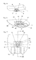
- FIG. 1 is a diagrammatic, perspective view of a closed container according to the state of the art
- FIG. 2 is a fragmentary, enlarged, vertical-sectional view through the uppermost region of the container of FIG. 1 ;
- FIGS. 3 and 4 are fragmentary vertical-sectional views of the uppermost region of the upside down container as shown in FIG. 2 in opposite relationship to or in connection with a container mounting of a dispenser;
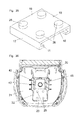
- FIG. 5 is a fragmentary perspective view of the uppermost region of a first embodiment according to the invention of a container in the position of use, without a closure;
- FIG. 6 is a fragmentary perspective view of the container mounting of a dispenser, matching the container of FIG. 5 ;
- FIG. 7 is a horizontal-sectional view through the container mounting of FIG. 6 with an inserted container
- FIG. 8 is a sectional view taken along a line VIII-VIII of FIG. 7 , in the direction of the arrows;
- FIGS. 9 and 10 are views corresponding to FIGS. 7 and 8 with a container according to the state of the art without a socket;
- FIG. 11 is a fragmentary perspective view of the uppermost region of a second embodiment according to the invention of a container in the position of use without a closure;
- FIG. 12 is a view of the container mounting of a dispenser, matching the container of FIG. 11 ;
- FIG. 13 is a horizontal-sectional view through the container mounting of FIG. 12 with an inserted container;
- FIG. 14 is a sectional view taken along a line XIV-XIV of FIG. 13 in the direction of the arrows;
- FIGS. 15 and 16 are views corresponding to FIGS. 13 and 14 with a container according to the state of the art without a socket;
- FIGS. 17 and 18 are fragmentary perspective views of the uppermost regions of a third and a fourth embodiment according to the invention of a container, in each case without a closure;
- FIG. 19 is a diagrammatic perspective view of a first embodiment of the dispenser for soap or the like.
- FIG. 20 is a perspective view of the uppermost region of a fifth and a sixth embodiment according to the invention of a container, inserted into an insert portion of the dispenser;
- FIG. 21 is a horizontal-sectional view taken along a line XXI-XXI of FIG. 22 in the direction of the arrows;
- FIG. 22 is a front-elevational view of the elements shown in FIG. 20 ;
- FIG. 23 is a perspective view of a seventh embodiment of a container with a closure
- FIG. 24 is a vertical-sectional view through the uppermost region of the container of FIG. 25 ;
- FIG. 25 is a diagrammatic perspective view of a second embodiment of the dispenser for soap or the like.
- FIG. 26 is a sectional view as shown in FIG. 8 or FIG. 14 through the container mounting with an opened container as shown in FIG. 25 ;
- FIG. 27 is a perspective view of a first embodiment of a lower portion of the dispenser of FIG. 25 ;
- FIG. 28 is a perspective view of a second embodiment of a lower portion of the dispenser of FIG. 25 ;
- FIG. 29 is a plan view of the embodiment of FIG. 28 with a closure disposed in the deposit device, without a container;
- FIG. 30 is an exploded perspective view showing a part of a third embodiment of a lower portion of the dispenser as shown in FIG. 25 ;
- FIGS. 31 and 32 respectively show a perspective view of a closure and a plan view of a third embodiment of a lower portion of the dispenser of FIG. 25 with the closure disposed in the deposit device, without a container;
- FIGS. 33 and 34 show a perspective view of a closure and a plan view of a fourth embodiment of a lower portion of the dispenser of FIG. 25 with the closure disposed in the deposit device, without a container;
- FIGS. 35 and 36 show a perspective view of a closure and a plan view of a fifth embodiment of a lower portion of the dispenser of FIG. 25 with the closure disposed in the deposit device, without a container.
- FIG. 1 there is seen a container 1 formed of soft flexible material, for example thin plastic film, which is approximately cuboidal and has an opening 3 formed in a wall provided in particular with a reinforcing plate 13 , in which the opening 3 is provided within a sealingly closable connection 2 or container neck.
- a reinforcing plate 13 extends over a large part of the area of the wall and with side limbs 14 embraces two oppositely disposed edges of the container 1 . Details about such a container 1 and its manufacture are to be found in the above-mentioned International Publication WO 2008/089500, corresponding to U.S. Pat. No. 8,561,844.
- the container 1 is intended in particular to receive liquid products like disinfectant, shampoo, soap or the like and, as shown in FIG. 19 or 25 , is fitted upside down into a dispenser 20 so that the wall provided with the reinforcing plate 13 and the connection 2 forms the support side or the container bottom.
- connection 2 carries a guide element 4 in the form of limbs 5 projecting at both sides as a prolongation of its end face, and a sealing ring 7 projecting slightly from the end face.
- a closure 10 is in the form of an approximately clip-shaped or C-shaped body which is pushed on from the side, in which case it engages behind the limbs 5 with guide elements 11 .
- FIGS. 3, 4, 6 through 10 and 12 through 16 respectively only show the single element that is important in that respect, namely the container mounting 40 on the cover plate 21 of the lower portion.
- the cover plate has an opening 46 which, when the container 1 is inserted and sealed by the sealing ring 7 , aligns with the connection 2 and the opening 3 of the container 1 ( FIGS. 4, 8, 14 ). As can be seen from the view in FIG.
- the container mounting 40 on the cover plate 20 is of the same structure in regard to the guide elements as the closure 10 and can therefore also engage with its guide elements 41 behind the limbs 5 of the connection 2 when the container 1 is inserted into the container mounting 40 . That is indicated in FIG. 6 showing the contour of the closure 10 in broken lines.
- the container 1 is therefore applied with the closure 10 to the container mounting 40 in front of the guide device elements 41 and is then inserted by way of a bevel 45 in the direction of an arrow A, in which case the closure 10 becomes free and remains disposed at the application point, as shown in FIG. 7 .
- a coding that is to say the container and the container mounting must be provided with mutually matching elements.
- at least one projection 42 is provided at the container mounting 40 and at least one corresponding socket 6 , 6 ′ ( FIGS. 5, 11 and 17 ) is provided at or in the connection 2 of each corresponding container 1 , the projection and the socket respectively extending in the slide direction (arrow A) of the container 1 . If the correct container is inserted then, as can be clearly seen from FIGS. 4, 8 and 14 , the openings 3 and 46 are aligned.
- FIG. 5 shows the upper region of a container 1 with a connection 2 in which there is provided a central socket 6 into which the central projection 42 shown in FIG. 6 engages.
- the cross-sections and lengths of the socket 6 and the projection 42 are the same.
- the inserted position in which the openings 5 and 46 are aligned can be clearly seen in the section in FIG. 8 .
- the provision of a single central socket 6 is advantageous if only one installation position of the container 1 is wanted.
- connection 2 is of an H-shape.
- the projection 42 has a cross-sectional area which is composed of a rectangle with an adjoined triangle.
- the closure 10 which is suited thereto can have a projection which fits into the second socket 6 ′ so that the closure 10 can be opened only towards that side.
- FIG. 11 shows the upper region of a second embodiment of a container 1 .
- the socket 6 is provided not centrally but laterally, and therefore a corner region of the connection 2 is missing.
- a second socket 6 ′ is preferably turned through 180°, as can be seen from FIG. 13 .
- FIG. 12 shows the associated container mounting 40 in which the projection 42 is also provided off-center in the corner region.
- the socket 6 and the projection 42 in this embodiment are of a trapezoidal cross-sectional area.
- FIG. 13 shows a horizontal section through the connection 2 of the container 1 fitted into the container mounting, in which case by virtue of the socket 6 the connection 2 can be inserted as far as the abutment 44 so that the openings 3 , 46 are aligned. That is again visible in the section in FIG. 14 .
- the sockets 6 , 6 ′ are provided on the connection 2 below the limbs 5 of the sliding guide, which thus extend over the entire depth or length.
- the socket 6 extends over the entire height of the connection 2 so that one of the two limbs 5 is shortened. Since more than half of the limb remains, neither the sealed seat of the closure 10 on the connection 2 nor the seat of the connection 2 in the container mounting 40 , is adversely affected.
- FIG. 18 shows it is also conceivable for the socket 6 to be produced by breaking off at least one tab 9 which is held to the connection 2 by way of intended breaking lines 8 .
- the projection 42 , the guide elements 41 and the transverse limb 44 are advantageously provided on an insert portion 43 which can be disposed in matching relationship with the containers to be used with that dispenser, in the cover plate 21 of the lower portion of the container 1 .
- FIGS. 20 through 22 show a hybrid form in which projections and sockets are provided both on the container 1 and also on the container mounting 40 .
- the container 1 (indicated in FIG. 22 ) again has a reinforcing plate 13 which with the oppositely disposed limbs 14 embraces two container edges.
- Each limb 14 has between one and six holes which form sockets 6 belonging to the container 1 and into which between one and six projections 42 can pass upon insertion of the container 1 into the container mounting 40 or its insert portion 43 .
- FIG. 20 shows for example two such projections 42 .
- FIGS. 20 through 22 further also show projections 12 in the form of limbs which project from connections 2 in the slide direction (arrow A) and penetrate into a corresponding orientation or socket 6 or a corresponding recess on the container mounting 40 when the container 1 is inserted.
- limbs 15 which extend in the slide direction approximately over the second half of the slide travel distance until they come to bear against the projection, which is visible in FIGS. 21 and 22 , of the inset portion 43 , in the form of an abutment 47 . In that end position the connection 2 bears against the transverse limb 44 while the projection 12 has passed into the socket 6 and the opening 3 aligns with the opening 46 (not shown in these figures) in the container mounting 40 .
- the abutment 47 is provided only at the left-hand side in the drawing and the second limb 15 provided at the right-hand side of the connection 2 does not impede insertion since an abutment 47 is missing at that side and a recess is thus also provided there.
- a container mounting 40 with an insert portion 43 as shown in FIGS. 20 through 22 prevents the insertion of conventional containers only by the projections 42 and the socket 6 in the region of the upstanding limbs 14 since no projections are provided, which require sockets on or in the connection 2 .
- Abutments 47 on the insert portion 43 or on the container mounting 40 itself as well as limbs 12 or 15 on the connection and the reinforcing plate 13 serve primarily to associate given products with given dispensers.
- FIG. 23 shows a perspective view of a second embodiment of a container 1 , on to the connection 2 of which there is pushed a closure 10 provided with a coding.
- the closure 10 shown in a number of configurations in FIGS. 23 through 34 as in the embodiments shown in FIGS. 1 through 22 , includes an approximately C-shaped body with limbs 11 which engage behind limbs 5 on the connection 2 and has a top side 19 parallel to the plane of the container opening 3 , two side surfaces 17 disposed in the slide direction (arrow A) of the container 1 and two side surfaces 18 perpendicular thereto.
- FIGS. 23 through 30 show closures 10 which in at least one of the two side surfaces 17 , have a recess 16 serving as coding in the form of a groove.
- the groove 16 extends perpendicularly to the plane of the container opening 3 while in FIG. 30 it extends inclined forwardly.
- the depth of the groove preferably corresponds to the wall thickness so that the limb 5 of the connection 2 is exposed or is not cut out. It is possible to see corresponding projections 24 in the form of noses or limbs on the dispenser immediately in front of the container mounting 40 as counterpart elements in relation to the recess 16 .
- FIG. 24 shows closures 10 which in at least one of the two side surfaces 17 , have a recess 16 serving as coding in the form of a groove.
- the groove 16 extends perpendicularly to the plane of the container opening 3 while in FIG. 30 it extends inclined forwardly.
- the depth of the groove preferably corresponds to the wall thickness so that the limb 5 of the connection 2 is exposed or is not
- a container 1 as shown in FIG. 23 can now be introduced into the position in front of the container mounting 40 either horizontally from the side ( FIG. 27 ), vertically from above ( FIGS. 28 and 29 ) or inclined from above ( FIG. 30 ). That signifies an at least approximately or precisely L-shaped travel path shown by two arrows B and A.
- the L-shaped path is parallel to the plane of the container opening 3 and to the plane of the opening 46 of the container mounting 40 and the closure 10 shown in FIG. 27 .
- the container which is not shown for the sake of clarity, moves over the first path portion corresponding to the arrow B into the chamber forming the deposit device 23 in front of the container mounting 40 , in which case the projection 24 passes into the recess 16 when the two coding elements are identical.
- the deposit device 23 is deeper than the container mounting 40 by the thickness of the top side of the closure 10 so that the container can be further displaced in the direction of the arrow A, wherein the closure 10 remains disposed in the deposit device 23 and the medium contained in the container 1 can flow away through the openings 3 and 46 into the lower portion of the dispenser 20 .
- the deposit device 23 is defined by limbs 22 so that it receives the closure 10 in a form-locking relationship.
- the container 1 is moved on to the closure 10 again upon removal in opposite relationship to the slide direction (arrow A) and is then removed in a condition of again being closed in opposite relationship to the arrow B from the dispenser.
- the container 1 can therefore also be exchanged while still partly filled without a partial quantity of its contents being lost.
- the closed containers are lowered vertically from above (arrow B) and the closure 10 is again in the deposit device 23 , as shown in FIG. 29 , and the container can then be inserted into the container mounting 40 (arrow A).
- FIG. 30 shows the inclined configuration of the coding elements 16 and 24 and thus also the inclined direction (arrow B) of insertion into the deposit device 23 .
- the second part of the travel path is again indicated by the arrow A into the container mounting 40 .
- FIGS. 27, 28 and 30 each show a perspective view illustrating the lower portion of a dispenser 20 with the cover plate 21 on which the container mounting 40 and an insert portion 43 corresponding to FIGS. 20 through 22 is provided.
- the only difference is the transverse limb 44 which is continuous over the width so that the container to be used in this case is without projections.
- the abutment 47 is missing, in comparison with the configuration shown in FIGS. 20 through 22 .
- FIGS. 31 and 32 show a closure 10 on which recesses 16 are provided in the narrow side surfaces 18 , wherein recesses are optionally also possible in the side surfaces as shown in FIG. 23 .
- the closure 10 shown in FIGS. 31 and 32 can only be introduced from above into the deposit device 23 so that insertion from the side, as shown in FIG. 27 , is not possible.
- the other two options shown in FIGS. 28 and 30 can also be implemented with the closure 10 of FIG. 31 .
- the closed container is inserted between the defining limbs 22 which project up from the cover plate 21 , into the deposit device 23 adjoining the container mounting 40 , the projections 24 passing into the recesses 16 ( FIG. 32 ).
- the container is now further pushed into the container mounting 40 , with the closure 10 remaining in the deposit device 23 .
- the container 1 If the container 1 is to be replaced when empty or when still partially filled it is moved back again into the deposit device 23 , in which case the closure 10 which is locked in that direction by the defining limb 22 is again pushed on to the connection 2 and sealingly closes the container. Subsequently the closed container is removed.
- a number of coding options are also afforded by a variation in the projections 24 , in the region of the deposit device 23 for the closure 10 .
- the projections 24 project from the edge of the container mounting 40 and engage into the recess 16 at the side surface 18 of the closure 10 .
- the closure 10 again remains in the deposit device 23 when the container 1 is pushed into the container mounting 40 .
- FIGS. 33 through 36 show coding elements at the top side 19 of the closure 10 , in which respect as shown in FIG. 33 the recesses 16 are in the form of cylindrical depressions, possibly also holes, while in FIG. 35 they are in the form of cylindrical projections 26 .
- the corresponding counterpart portions are provided in the bottom surface of the deposit device 23 , that is to say as shown in FIG. 34 the projections 28 shown in broken lines project there in the form of cylindrical knobs or the like and in FIG. 36 depressions 25 are in the form for example of cylindrical blind holes in the cover 21 .
- Projections 24 , 27 , 28 (limbs, noses, knobs and so forth) projecting into the deposit device 23 allow holes in the cover plate 21 , which are covered over by the projections 24 , 27 , 28 , to provide tamper protection. If those projections of the deposit device 23 are removed in order to be able to insert for example containers 1 as shown in FIG. 1 without a recess 16 in the closure 10 then those holes are exposed.
- a chamber in particular an intermediate container, a pump chamber or the like, into which the liquid flows out of the container 1 fitted into the container mounting 40 ( FIG. 19 ) and which loses sealing integrity due to the removal of the projection 24 .
- FIGS. 29 and 32 the closure 10 is sectioned in each case parallel to the plane of the container opening 3 whereby engagement of the projections 24 into the recess 16 is more clearly apparent.
- the section plane extends directly beneath the limbs 11 of the closure 10 .
- FIGS. 34 and 36 are in the same position, with the closure 10 not being shown in FIG. 36 .
- the projections 24 projecting into the deposit device 23 are subdivided horizontally whereby a second projection 27 remains at the bottom of the deposit device 23 , and that projection, as mentioned above, exposes a hole in the cover when it is removed.
Landscapes
- Engineering & Computer Science (AREA)
- Mechanical Engineering (AREA)
- Health & Medical Sciences (AREA)
- Public Health (AREA)
- Closures For Containers (AREA)
- Containers And Packaging Bodies Having A Special Means To Remove Contents (AREA)
Applications Claiming Priority (4)
| Application Number | Priority Date | Filing Date | Title |
|---|---|---|---|
| AT976/2013 | 2013-12-20 | ||
| ATA976/2013A AT515275B1 (de) | 2013-12-20 | 2013-12-20 | Behälter |
| ATA976/2013 | 2013-12-20 | ||
| PCT/AT2014/000223 WO2015089532A2 (de) | 2013-12-20 | 2014-12-15 | Behälter |
Related Parent Applications (1)
| Application Number | Title | Priority Date | Filing Date |
|---|---|---|---|
| PCT/AT2014/000223 Continuation WO2015089532A2 (de) | 2013-12-20 | 2014-12-15 | Behälter |
Publications (2)
| Publication Number | Publication Date |
|---|---|
| US20160297573A1 US20160297573A1 (en) | 2016-10-13 |
| US10322852B2 true US10322852B2 (en) | 2019-06-18 |
Family
ID=53267184
Family Applications (1)
| Application Number | Title | Priority Date | Filing Date |
|---|---|---|---|
| US15/186,721 Active 2035-07-14 US10322852B2 (en) | 2013-12-20 | 2016-06-20 | Container and dispensing system having the container |
Country Status (16)
| Country | Link |
|---|---|
| US (1) | US10322852B2 (de) |
| EP (1) | EP3083441B1 (de) |
| CN (1) | CN106414262A (de) |
| AT (1) | AT515275B1 (de) |
| AU (1) | AU2014366864B2 (de) |
| CA (1) | CA2933044C (de) |
| EA (1) | EA031979B1 (de) |
| ES (1) | ES2966092T3 (de) |
| HR (1) | HRP20231468T1 (de) |
| HU (1) | HUE063928T2 (de) |
| IL (1) | IL246016B (de) |
| MX (1) | MX379470B (de) |
| PL (1) | PL3083441T3 (de) |
| RS (1) | RS64697B1 (de) |
| WO (1) | WO2015089532A2 (de) |
| ZA (1) | ZA201603904B (de) |
Citations (13)
| Publication number | Priority date | Publication date | Assignee | Title |
|---|---|---|---|---|
| US2472582A (en) | 1946-05-04 | 1949-06-07 | William E Green | Food container |
| CH264561A (de) | 1948-10-23 | 1949-10-31 | Ruetz Joseph | Verschliesseinrichtung an Behältern. |
| GB984593A (en) | 1962-04-17 | 1965-02-24 | Charles Nicolle Ets | Device for the inviolable closure of a container |
| US4570827A (en) | 1984-03-28 | 1986-02-18 | Essex Chemical Corp. | Liquid dispenser |
| WO1995009111A1 (de) | 1993-09-28 | 1995-04-06 | Hagleitner Betriebshygiene Gesellschaft Mbh | Behälter aus thermoplastischem kunststoff und verfahren zu seiner herstellung |
| US6212721B1 (en) | 2000-04-17 | 2001-04-10 | German Borodulin | Opener and stopper for crimped and threaded bottle caps |
| EP1118301A1 (de) | 2000-01-19 | 2001-07-25 | Cws International Ag | Vorrichtung zur Abgabe von Seifenlösung in einem Spender |
| US6314262B1 (en) | 1999-07-23 | 2001-11-06 | Sharp Kabushiki Kaisha | Toner supply system and toner cartridge |
| US20040232168A1 (en) | 2002-07-25 | 2004-11-25 | Joseph Kanfer | Wall-mounted dispenser assembly with transparent window |
| EP1719441A1 (de) | 2005-05-03 | 2006-11-08 | JohnsonDiversey, Inc. | Seifenspender |
| US20070108207A1 (en) | 2003-11-24 | 2007-05-17 | Pierre Malek | Device for storing tools with a clip lid |
| WO2008089500A2 (de) | 2007-01-23 | 2008-07-31 | Hans Georg Hagleitner | Behälter |
| US20090026225A1 (en) | 2007-07-23 | 2009-01-29 | Conopco, Inc., D/B/A Unilever | Household liquid dispenser with keyed spout fitment and refill |
-
2013
- 2013-12-20 AT ATA976/2013A patent/AT515275B1/de active
-
2014
- 2014-12-15 WO PCT/AT2014/000223 patent/WO2015089532A2/de not_active Ceased
- 2014-12-15 PL PL14866793.4T patent/PL3083441T3/pl unknown
- 2014-12-15 ES ES14866793T patent/ES2966092T3/es active Active
- 2014-12-15 CA CA2933044A patent/CA2933044C/en active Active
- 2014-12-15 RS RS20230956A patent/RS64697B1/sr unknown
- 2014-12-15 HU HUE14866793A patent/HUE063928T2/hu unknown
- 2014-12-15 MX MX2016008237A patent/MX379470B/es unknown
- 2014-12-15 CN CN201480073617.4A patent/CN106414262A/zh active Pending
- 2014-12-15 HR HRP20231468TT patent/HRP20231468T1/hr unknown
- 2014-12-15 AU AU2014366864A patent/AU2014366864B2/en active Active
- 2014-12-15 EP EP14866793.4A patent/EP3083441B1/de active Active
- 2014-12-15 EA EA201691291A patent/EA031979B1/ru not_active IP Right Cessation
-
2016
- 2016-06-05 IL IL246016A patent/IL246016B/en active IP Right Grant
- 2016-06-08 ZA ZA2016/03904A patent/ZA201603904B/en unknown
- 2016-06-20 US US15/186,721 patent/US10322852B2/en active Active
Patent Citations (18)
| Publication number | Priority date | Publication date | Assignee | Title |
|---|---|---|---|---|
| US2472582A (en) | 1946-05-04 | 1949-06-07 | William E Green | Food container |
| CH264561A (de) | 1948-10-23 | 1949-10-31 | Ruetz Joseph | Verschliesseinrichtung an Behältern. |
| GB984593A (en) | 1962-04-17 | 1965-02-24 | Charles Nicolle Ets | Device for the inviolable closure of a container |
| US4570827A (en) | 1984-03-28 | 1986-02-18 | Essex Chemical Corp. | Liquid dispenser |
| WO1995009111A1 (de) | 1993-09-28 | 1995-04-06 | Hagleitner Betriebshygiene Gesellschaft Mbh | Behälter aus thermoplastischem kunststoff und verfahren zu seiner herstellung |
| US5730694A (en) | 1993-09-28 | 1998-03-24 | Hagleitner Betriebshygiene Gesellschaft M.B.H. & Co. Kg | Container of thermoplastic material and process for the production thereof |
| US6314262B1 (en) | 1999-07-23 | 2001-11-06 | Sharp Kabushiki Kaisha | Toner supply system and toner cartridge |
| EP1118301A1 (de) | 2000-01-19 | 2001-07-25 | Cws International Ag | Vorrichtung zur Abgabe von Seifenlösung in einem Spender |
| US6758372B2 (en) | 2000-01-19 | 2004-07-06 | Hts International Trading Ag | Device for dispensing soap-solution in a dispenser |
| US6212721B1 (en) | 2000-04-17 | 2001-04-10 | German Borodulin | Opener and stopper for crimped and threaded bottle caps |
| US20040232168A1 (en) | 2002-07-25 | 2004-11-25 | Joseph Kanfer | Wall-mounted dispenser assembly with transparent window |
| US20070108207A1 (en) | 2003-11-24 | 2007-05-17 | Pierre Malek | Device for storing tools with a clip lid |
| EP1719441A1 (de) | 2005-05-03 | 2006-11-08 | JohnsonDiversey, Inc. | Seifenspender |
| US8261945B2 (en) | 2005-05-03 | 2012-09-11 | Diversey, Inc. | Soap dispensing apparatus |
| WO2008089500A2 (de) | 2007-01-23 | 2008-07-31 | Hans Georg Hagleitner | Behälter |
| US20090272752A1 (en) | 2007-01-23 | 2009-11-05 | Hans Georg Hagleitner | Container, Dispensing System for Flowable Products, and Production Method |
| US20090026225A1 (en) | 2007-07-23 | 2009-01-29 | Conopco, Inc., D/B/A Unilever | Household liquid dispenser with keyed spout fitment and refill |
| WO2009013173A2 (en) | 2007-07-23 | 2009-01-29 | Unilever Plc | Household liquid dispenser with keyed spout fitment and refill |
Also Published As
| Publication number | Publication date |
|---|---|
| CA2933044C (en) | 2018-12-11 |
| ZA201603904B (en) | 2017-08-30 |
| EP3083441B1 (de) | 2023-09-27 |
| MX379470B (es) | 2025-03-10 |
| CA2933044A1 (en) | 2015-06-25 |
| AU2014366864B2 (en) | 2018-04-19 |
| EA201691291A1 (ru) | 2016-10-31 |
| US20160297573A1 (en) | 2016-10-13 |
| AT515275B1 (de) | 2018-06-15 |
| RS64697B1 (sr) | 2023-11-30 |
| WO2015089532A2 (de) | 2015-06-25 |
| HRP20231468T1 (hr) | 2024-03-01 |
| WO2015089532A3 (de) | 2016-06-30 |
| AT515275A1 (de) | 2015-07-15 |
| HUE063928T2 (hu) | 2024-02-28 |
| PL3083441T3 (pl) | 2024-04-08 |
| EP3083441A2 (de) | 2016-10-26 |
| IL246016A0 (en) | 2016-07-31 |
| CN106414262A (zh) | 2017-02-15 |
| ES2966092T3 (es) | 2024-04-18 |
| AU2014366864A1 (en) | 2016-07-07 |
| MX2016008237A (es) | 2016-10-24 |
| EP3083441C0 (de) | 2023-09-27 |
| EA031979B1 (ru) | 2019-03-29 |
| IL246016B (en) | 2021-02-28 |
Similar Documents
| Publication | Publication Date | Title |
|---|---|---|
| US6662454B2 (en) | Child resistant, disposable, premeasured dosage spoon | |
| US11058262B2 (en) | Dispensing system for a flowable product | |
| US9387965B2 (en) | One-piece squeeze-to-dose dispensing closure | |
| US8646659B2 (en) | Dispensing container for dispensing predetermined amounts of product | |
| CN114222704A (zh) | 分配闭合件 | |
| HU224240B1 (hu) | Adagoló tárolóedényhez | |
| US10322852B2 (en) | Container and dispensing system having the container | |
| JP6137996B2 (ja) | スクイズ式計量容器 | |
| US20250180389A1 (en) | Adjustable rotary cup | |
| DE102009022315B4 (de) | Verschluss für ein Behältnis | |
| ITVI20120328A1 (it) | Dispositivo erogatore per recipienti e contenitore per un prodotto in polvere comprendente tale dispositivo erogatore | |
| ITMI20040404U1 (it) | Tappo antimanomissione per contenitori associati a pompe dosatrici | |
| JP6407655B2 (ja) | 注出具、及びスパウト付き収容体 | |
| ITMI20011790A1 (it) | Contenitore-erogatore automatico per liquidi igienizzanti e deodoranti per wc | |
| ITMI20020610U1 (it) | Tappo antimanomissione per contenitori associati a pompe dosatrici | |
| ITBS970003A1 (it) | Contenitore di prodotto concentrato per la preparazione di una bevanda in distributori di bevande | |
| ITPI980016U1 (it) | Cucchiaino con inforporato o applicato un contenitore per il dolcificante od altra sostanza | |
| CZ12661U1 (cs) | Uzavírací zařízení |
Legal Events
| Date | Code | Title | Description |
|---|---|---|---|
| STPP | Information on status: patent application and granting procedure in general |
Free format text: NOTICE OF ALLOWANCE MAILED -- APPLICATION RECEIVED IN OFFICE OF PUBLICATIONS |
|
| STCF | Information on status: patent grant |
Free format text: PATENTED CASE |
|
| MAFP | Maintenance fee payment |
Free format text: PAYMENT OF MAINTENANCE FEE, 4TH YEAR, LARGE ENTITY (ORIGINAL EVENT CODE: M1551); ENTITY STATUS OF PATENT OWNER: LARGE ENTITY Year of fee payment: 4 |