US10276891B2 - Electrolytes for calcium-based secondary cell and calcium-based secondary cell comprising the same - Google Patents
Electrolytes for calcium-based secondary cell and calcium-based secondary cell comprising the same Download PDFInfo
- Publication number
- US10276891B2 US10276891B2 US15/516,493 US201415516493A US10276891B2 US 10276891 B2 US10276891 B2 US 10276891B2 US 201415516493 A US201415516493 A US 201415516493A US 10276891 B2 US10276891 B2 US 10276891B2
- Authority
- US
- United States
- Prior art keywords
- calcium
- electrolyte
- negative electrode
- active material
- cell
- Prior art date
- Legal status (The legal status is an assumption and is not a legal conclusion. Google has not performed a legal analysis and makes no representation as to the accuracy of the status listed.)
- Active, expires
Links
Images


Classifications
-
- H—ELECTRICITY
- H01—ELECTRIC ELEMENTS
- H01M—PROCESSES OR MEANS, e.g. BATTERIES, FOR THE DIRECT CONVERSION OF CHEMICAL ENERGY INTO ELECTRICAL ENERGY
- H01M10/00—Secondary cells; Manufacture thereof
- H01M10/05—Accumulators with non-aqueous electrolyte
- H01M10/054—Accumulators with insertion or intercalation of metals other than lithium, e.g. with magnesium or aluminium
-
- H—ELECTRICITY
- H01—ELECTRIC ELEMENTS
- H01M—PROCESSES OR MEANS, e.g. BATTERIES, FOR THE DIRECT CONVERSION OF CHEMICAL ENERGY INTO ELECTRICAL ENERGY
- H01M10/00—Secondary cells; Manufacture thereof
- H01M10/05—Accumulators with non-aqueous electrolyte
- H01M10/056—Accumulators with non-aqueous electrolyte characterised by the materials used as electrolytes, e.g. mixed inorganic/organic electrolytes
- H01M10/0564—Accumulators with non-aqueous electrolyte characterised by the materials used as electrolytes, e.g. mixed inorganic/organic electrolytes the electrolyte being constituted of organic materials only
- H01M10/0566—Liquid materials
- H01M10/0568—Liquid materials characterised by the solutes
-
- H—ELECTRICITY
- H01—ELECTRIC ELEMENTS
- H01M—PROCESSES OR MEANS, e.g. BATTERIES, FOR THE DIRECT CONVERSION OF CHEMICAL ENERGY INTO ELECTRICAL ENERGY
- H01M10/00—Secondary cells; Manufacture thereof
- H01M10/05—Accumulators with non-aqueous electrolyte
- H01M10/056—Accumulators with non-aqueous electrolyte characterised by the materials used as electrolytes, e.g. mixed inorganic/organic electrolytes
- H01M10/0564—Accumulators with non-aqueous electrolyte characterised by the materials used as electrolytes, e.g. mixed inorganic/organic electrolytes the electrolyte being constituted of organic materials only
- H01M10/0566—Liquid materials
- H01M10/0569—Liquid materials characterised by the solvents
-
- H—ELECTRICITY
- H01—ELECTRIC ELEMENTS
- H01M—PROCESSES OR MEANS, e.g. BATTERIES, FOR THE DIRECT CONVERSION OF CHEMICAL ENERGY INTO ELECTRICAL ENERGY
- H01M10/00—Secondary cells; Manufacture thereof
- H01M10/60—Heating or cooling; Temperature control
- H01M10/61—Types of temperature control
- H01M10/617—Types of temperature control for achieving uniformity or desired distribution of temperature
-
- H—ELECTRICITY
- H01—ELECTRIC ELEMENTS
- H01M—PROCESSES OR MEANS, e.g. BATTERIES, FOR THE DIRECT CONVERSION OF CHEMICAL ENERGY INTO ELECTRICAL ENERGY
- H01M10/00—Secondary cells; Manufacture thereof
- H01M10/60—Heating or cooling; Temperature control
- H01M10/65—Means for temperature control structurally associated with the cells
- H01M10/656—Means for temperature control structurally associated with the cells characterised by the type of heat-exchange fluid
- H01M10/6561—Gases
- H01M10/6563—Gases with forced flow, e.g. by blowers
-
- H—ELECTRICITY
- H01—ELECTRIC ELEMENTS
- H01M—PROCESSES OR MEANS, e.g. BATTERIES, FOR THE DIRECT CONVERSION OF CHEMICAL ENERGY INTO ELECTRICAL ENERGY
- H01M10/00—Secondary cells; Manufacture thereof
- H01M10/60—Heating or cooling; Temperature control
- H01M10/65—Means for temperature control structurally associated with the cells
- H01M10/657—Means for temperature control structurally associated with the cells by electric or electromagnetic means
- H01M10/6571—Resistive heaters
-
- H—ELECTRICITY
- H01—ELECTRIC ELEMENTS
- H01M—PROCESSES OR MEANS, e.g. BATTERIES, FOR THE DIRECT CONVERSION OF CHEMICAL ENERGY INTO ELECTRICAL ENERGY
- H01M4/00—Electrodes
- H01M4/02—Electrodes composed of, or comprising, active material
- H01M4/13—Electrodes for accumulators with non-aqueous electrolyte, e.g. for lithium-accumulators; Processes of manufacture thereof
- H01M4/134—Electrodes based on metals, Si or alloys
-
- H—ELECTRICITY
- H01—ELECTRIC ELEMENTS
- H01M—PROCESSES OR MEANS, e.g. BATTERIES, FOR THE DIRECT CONVERSION OF CHEMICAL ENERGY INTO ELECTRICAL ENERGY
- H01M4/00—Electrodes
- H01M4/02—Electrodes composed of, or comprising, active material
- H01M4/36—Selection of substances as active materials, active masses, active liquids
- H01M4/38—Selection of substances as active materials, active masses, active liquids of elements or alloys
- H01M4/381—Alkaline or alkaline earth metals elements
-
- H—ELECTRICITY
- H01—ELECTRIC ELEMENTS
- H01M—PROCESSES OR MEANS, e.g. BATTERIES, FOR THE DIRECT CONVERSION OF CHEMICAL ENERGY INTO ELECTRICAL ENERGY
- H01M4/00—Electrodes
- H01M4/02—Electrodes composed of, or comprising, active material
- H01M4/36—Selection of substances as active materials, active masses, active liquids
- H01M4/38—Selection of substances as active materials, active masses, active liquids of elements or alloys
- H01M4/386—Silicon or alloys based on silicon
-
- H—ELECTRICITY
- H01—ELECTRIC ELEMENTS
- H01M—PROCESSES OR MEANS, e.g. BATTERIES, FOR THE DIRECT CONVERSION OF CHEMICAL ENERGY INTO ELECTRICAL ENERGY
- H01M4/00—Electrodes
- H01M4/02—Electrodes composed of, or comprising, active material
- H01M4/36—Selection of substances as active materials, active masses, active liquids
- H01M4/38—Selection of substances as active materials, active masses, active liquids of elements or alloys
- H01M4/387—Tin or alloys based on tin
-
- H—ELECTRICITY
- H01—ELECTRIC ELEMENTS
- H01M—PROCESSES OR MEANS, e.g. BATTERIES, FOR THE DIRECT CONVERSION OF CHEMICAL ENERGY INTO ELECTRICAL ENERGY
- H01M10/00—Secondary cells; Manufacture thereof
- H01M10/60—Heating or cooling; Temperature control
- H01M10/61—Types of temperature control
- H01M10/613—Cooling or keeping cold
-
- H—ELECTRICITY
- H01—ELECTRIC ELEMENTS
- H01M—PROCESSES OR MEANS, e.g. BATTERIES, FOR THE DIRECT CONVERSION OF CHEMICAL ENERGY INTO ELECTRICAL ENERGY
- H01M10/00—Secondary cells; Manufacture thereof
- H01M10/60—Heating or cooling; Temperature control
- H01M10/61—Types of temperature control
- H01M10/615—Heating or keeping warm
-
- H—ELECTRICITY
- H01—ELECTRIC ELEMENTS
- H01M—PROCESSES OR MEANS, e.g. BATTERIES, FOR THE DIRECT CONVERSION OF CHEMICAL ENERGY INTO ELECTRICAL ENERGY
- H01M2300/00—Electrolytes
- H01M2300/0017—Non-aqueous electrolytes
- H01M2300/0025—Organic electrolyte
- H01M2300/0028—Organic electrolyte characterised by the solvent
- H01M2300/0037—Mixture of solvents
- H01M2300/004—Three solvents
-
- Y—GENERAL TAGGING OF NEW TECHNOLOGICAL DEVELOPMENTS; GENERAL TAGGING OF CROSS-SECTIONAL TECHNOLOGIES SPANNING OVER SEVERAL SECTIONS OF THE IPC; TECHNICAL SUBJECTS COVERED BY FORMER USPC CROSS-REFERENCE ART COLLECTIONS [XRACs] AND DIGESTS
- Y02—TECHNOLOGIES OR APPLICATIONS FOR MITIGATION OR ADAPTATION AGAINST CLIMATE CHANGE
- Y02E—REDUCTION OF GREENHOUSE GAS [GHG] EMISSIONS, RELATED TO ENERGY GENERATION, TRANSMISSION OR DISTRIBUTION
- Y02E60/00—Enabling technologies; Technologies with a potential or indirect contribution to GHG emissions mitigation
- Y02E60/10—Energy storage using batteries
Definitions
- the present disclosure discloses electrolytes particularly suitable for use in a calcium-based secondary cell, a calcium-based secondary cell which can be effectively operated under mild temperature and voltage conditions, a non-aqueous secondary battery containing the cell as well as a vehicle, an electronic device or a stationary power generating device containing the battery.
- Secondary (i.e. rechargeable) electrochemical cells and batteries are a power source widely used in information-related devices, communication devices (such as personal computers, camcorders and cellular phones) as well as in the automobile industry or in stationary power generating devices.
- Conventional lithium-based cells typically include a positive electrode (also referred to as “cathode”) and a negative electrode (also referred to as “anode”) whose active materials are capable of accepting and releasing lithium ions, as well as an electrolyte arranged between the electrodes and including lithium ions. Lifetime of conventional lithium-based secondary cells and batteries is not always satisfactory.
- SEI solid-electrolyte interphase
- SEI solid electrolyte interphase
- the interphase is thought to prevent further decomposition of the electrolyte upon battery cycling.
- SEI thus seems to play a key role in controlling cell electrochemical process, delaying of capacity fade, setting cycle life and ultimately determining cell performances. For this reason it would be desirable to provide a secondary cell/battery endowed with of a good quality SEI and/or operate the same to minimize the impact that SEI with unsatisfactory quality may have on cell/battery performances.
- Energy storage properties are further aspects that are not always satisfactory in conventional lithium-based secondary cells and batteries.
- the cell should be rechargeable when operated under mild temperature conditions and potential windows so as to be a commercially viable energy storage device compatible with a vast panel of final applications.
- the present disclosure discloses electrolytes particularly suitable for use in a calcium-based secondary cell, a calcium-based secondary cell which can be effectively operated under advantageous temperature and voltage conditions, a non-aqueous secondary battery containing the cell as well as a vehicle, an electronic device or a stationary power generating device containing the battery.
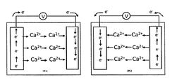
- FIG. 1 is a schematic view of a calcium-based secondary cell
- FIG. 2 are diagrams reporting cyclic voltamperommetry measurements proving the electrodeposition and stripping of calcium electrodes in certain experimental conditions. Tests conditions are 0.3M Ca(ClO 4 ) 2 in EC 0.5 :PC 0.5 ; a) at 1 mV/s and various temperatures; b) at 50° C. and various sweep rates. Current collector is stainless steel;
- FIG. 3 is a picture of a stainless steel after calcium electroplating mode at ⁇ 1 V vs. Ca 2+ /Ca in 0.3M Ca(BF 4 ) 2 in EC 0.5 :PC 0.5 at 75° C.;
- FIG. 4 are three scanning electron microscope images of copper electrode a) before and b), c) after calcium deposition in 0.3M Ca(BF 4 ) 2 in EC 0.45 :PC 0.45 :DMC 0.1 . Calcium deposits were achieved at 75° C. in potentiostatic mode at b) ⁇ 1 V vs. Ca 2+ /Ca during 80 h and c) ⁇ 1.5 V vs. Ca 2+ /Ca during 200 h;
- FIG. 5 is a diagram reporting the EDS quantitative analysis on calcium deposited in experiment c) as defined in FIG. 4 ;
- FIG. 6 is a diagram reporting the synchrotron X-ray diffraction pattern of the deposit formed on a copper disk and stainless steel plunger after calcium deposition in 0.3M Ca(BF 4 ) 2 in EC 0.45 :PC 0.45 :DMC 0.1 achieved in potentiostatic mode at ⁇ 1.5 V vs. Ca 2+ /Ca during 200 h;
- FIG. 7 is a diagram reporting cyclic voltamperommetry measurements on electrodeposited calcium obtained after 200 h potentiostatic deposition at ⁇ 1.5 V vs. Ca 2+ /Ca, the electrolyte being 0.3M Ca(BF 4 ) 2 in EC 0.45 :PC 0.45 :DMC 0.1 using various current collectors (calcium, aluminum, gold). In all cases, the sweep rate was 1 mV/s;
- FIG. 8 is a diagram reporting cyclic voltamperommetry measurements on electrodeposited calcium obtained after 200 h potentiostatic deposition at ⁇ 1.5 V vs. Ca 2+ /Ca, the electrolyte being Ca(BF 4 ) 2 in EC 0.45 :PC 0.45 :DMC 0.1 at various salt concentrations (0.3, 0.65 and 1 M). In all cases, the sweep rate was 1 mV/s and the current collector was gold;
- FIG. 9 is a diagram reporting PITT measurements of composite film negative electrode containing tin electrodes cycled in 0.3M Ca(BF 4 ) 2 in EC 0.45 :PC 0.45 :DMC 0.1 at 75° C.;
- FIG. 10 are two pictures representing scanning electron microscopy images of composite powder electrode (composition: tin 80% wt. and conductive carbon black 20% wt.—conductive carbon black was Carbon Super P®, also referred to as “C sp ” commercially available from TIMCAL) a) before and b) after a complete reduction (PITT measurements). Cycling was performed at 75° C. using 0.3M Ca(BF 4 ) 2 in EC 0.45 :PC 0.45 :DMC 0.1 electrolyte;
- FIG. 11 is a diagram reporting the particle size distribution of tin particles used in experiments a) and b) as per FIG. 10 ;
- FIG. 12 is a diagram reporting the PITT measurements of composite film negative electrode containing silicon cycled in 0.3M Ca(BF 4 ) 2 in EC 0.45 :PC 0.45 :DMC 0.1 at 75° C.;
- FIG. 13 are diagrams reporting cyclic voltamperommetry measurements proving the electrodeposition and stripping of calcium electrodes in certain experimental conditions. Tests conditions are 0.3M Ca(BF 4 ) 2 in EC 0.5 :PC 0.5 at 100° C. Current collector is stainless steel. Cycles 1, 2, 3 and 10 are reported on FIGS. 13 a, b, c and d , respectively.
- the present disclosure discloses an electrolyte comprising, such as consisting of calcium ions and an electrolyte medium, wherein the electrolyte is not solid at standard conditions and wherein the electrolyte medium includes at least two distinct non-aqueous solvents.
- the electrolyte is not solid at a temperature of about 20° C. and a pressure of 1 atm (hereinafter also referred to as standard conditions). Unless otherwise indicated, “not solid” means that at standard conditions, the electrolyte may be a liquid, a viscous mass or a gel. For example it has a viscosity of lower than 10 cP, such as lower than 8 cP, for example lower than 5 cP, when measured using a rheometer (for example a RheoStress RS600 Rheometer available from HAAKE) at standard conditions.
- a rheometer for example a RheoStress RS600 Rheometer available from HAAKE
- the electrolyte presently disclosed is endowed with one or more, such as all of the following properties:
- Calcium ions may be in the form of a calcium salt, for example and inorganic calcium salt and/or an organic calcium salt.
- the salt is anhydrous.
- the salt may be selected from the group consisting of calcium tetrafluoroborate (Ca(BF 4 ) 2 ), calcium perchlorate (Ca(ClO 4 ) 2 ) calcium hexafluorophosphate (Ca(PF 6 ) 2 ), Ca(CF 3 SO 3 ) 2 and mixtures thereof. (Ca(BF 4 ) 2 ) and mixtures thereof may be preferred.
- the salt may be dissolved in the electrolyte medium.
- the salt may be present in an amount comprised between 0.05M and 2M, such as between 0.1M and 1M, with respect to the volume of the electrolyte.
- the electrolyte may be substantially free of other metal ions of Group I and II of the period table—for example lithium ions, sodium ions, potassium ions. This means that the amount of metal ions other than calcium possibly presents in the electrolyte is electrochemically ineffective.
- each solvent present in the medium is substantially free of water.
- substantially free of water means that the solvent may include water in an amount equal to or lower than 300 ppm, such as equal to or lower than 50 ppm, as measured with the Karl Fischer titration technique.
- each solvent present in the medium and/or the combination thereof is stable at a temperature comprised between at least ⁇ 30 and 150° C. (stability window).
- Each solvent present in the medium may independently be selected from the group consisting of cyclic carbonates, linear carbonates, cyclic esters, cyclic ethers, linear ethers and mixtures thereof.
- Cyclic carbonates may be selected from the group consisting of ethylene carbonate (EC), propylene carbonate (PC), butylene carbonate, vinylene carbonate, fluoroethylenecarbonate (FEC) and mixtures thereof.
- Linear carbonates may be selected from the group consisting of dimethyl carbonate (DMC), diethylcarbonate (DEC), ethyl methyl carbonate (EMC), and mixtures thereof.
- DMC dimethyl carbonate
- DEC diethylcarbonate
- EMC ethyl methyl carbonate
- Cyclic ester carbonates may be ⁇ -buryrolactone and/or ⁇ -valerolactone.
- Cyclic ethers may be tetrahydrofuran (THF) and/or 2-methyltetrahydrofuran.
- Linear ethers may be selected from the group consisting of dimethoxyethane (DME), ethylene glycol dimethyl ether, triethylene glycol dimethyl ether (TEDGE), tetraethyleneglycol dimethyl ether (TEDGE), and mixtures thereof.
- DME dimethoxyethane
- TEDGE triethylene glycol dimethyl ether
- TEDGE tetraethyleneglycol dimethyl ether
- the solvent may include dimethylsulfoxide (DMSO) or nitrile solvents (such as acetonitrile, propionitrile, and 3-methoxypropionitrile).
- DMSO dimethylsulfoxide
- nitrile solvents such as acetonitrile, propionitrile, and 3-methoxypropionitrile
- the electrolyte medium may include ethylene carbonate (EC) and propylene carbonate (PC), such as a combination of formula EC h :PC 1-h wherein the ratio is expressed as volume:volume and h is 0 ⁇ h ⁇ 1, such as 0.2 ⁇ h ⁇ 0.8 or h is 0.5.
- EC ethylene carbonate
- PC propylene carbonate
- Mixtures of ethylene carbonate (EC) and propylene carbonate (PC) may be stable between ⁇ 90° C. and 240° C.
- EC ethylene carbonate
- PC propylene carbonate
- DMC dimethyl carbonate
- the at least two solvents may be present in a total (i.e. combined) amount comprised between about 50 and 99% by mass, with respect to 100% by mass of the electrolyte.
- the solvents may be present in an amount comprised between about 70 and 99% by mass, with respect to 100% by mass of the electrolyte. This range is preferred for having liquid electrolytes.
- the electrolyte medium further includes a polymer—such as a gelling polymer—the solvents are advantageously present in an amount comprised between about 50 and 70% by mass, with respect to 100% by mass of the electrolyte. This range is preferred for having gel polymer electrolytes.
- the electrolyte medium may further include a component (such as crown ethers) that facilitates calcium salt dissociation and/or enhance calcium salts dissolution.
- a component such as crown ethers
- the electrolyte medium may further include a gelling polymer. This is typically the case of gel polymer electrolytes.
- the gelling polymer may be selected from the group consisting of polyethylene oxide (PEO), polyvinylidene fluoride (PVDF), polyacrylonitrile (PAN), polymethyl methacrylate (PMMA), poly(vinyl) chloride (PVC), and mixtures thereof.
- PEO polyethylene oxide
- PVDF polyvinylidene fluoride
- PAN polyacrylonitrile
- PMMA polymethyl methacrylate
- PVC poly(vinyl) chloride
- the electrolyte medium may further comprise a filler, the filler including:
- Nanoparticles/nanoceramics may include Al 2 O 3 , SiO 2 , ZrO 2 , MgO, and/or CeO 2 and may have an average particle size equal to or lower than about 15 nm (this value can be measured by methods disclosed above). This component may be added to increase the electrolyte conductivity.
- Suitable Al 2 O 3 nanoparticles having an average particle size of 5.8 nm are commercially available from Aldrich Research Grade.
- Suitable SiO 2 nanoparticles having an average particle size of 7.0 nm are commercially available from Aldrich Research Grade,
- the filler may be present in an amount of lower than 10% by weight over the weight of the total gel polymer electrolyte.
- the electrolyte presently disclosed was found to lead to the formation of a good quality SEI at the negative electrode when the electrolyte is used in the context of a calcium-based secondary cell. Despite it is not intended to be bound by any theory, it is believed that a good quality SEI is important for ions proper conductivity thereby improving cell/battery performances.
- the present disclosure discloses a calcium-based secondary cell comprising:
- the negative electrode may be an electrode comprising a negative-electrode active material, said active material including metallic calcium or a calcium alloy.
- the alloy has formula (I) Ca m B wherein m is 0 ⁇ m ⁇ 3 and B is a metal or a semi-conductor element.
- the negative electrode may consist of a negative electrode active material as presently defined.
- the negative electrode active material includes, such as consist of, metallic calcium (hereinafter also referred to as “calcium metal”).
- calcium metal metallic calcium
- Preference is due for example to the “theoretical” large capacity of calcium metal (1.34 Ah/g) and its optimal potential vs. Ca 2+ /Ca.
- the negative electrode may be for example a foil of metallic calcium.
- the metallic calcium may also play the role of current collector.
- a pre-formed, metallic calcium-containing negative electrode can thus be used during assembly of a calcium-based secondary electrochemical cell.
- the negative electrode may include, such as consist of a support, such as a current collector, having a metallic calcium coating as negative-electrode active material.
- the coating is obtainable by depositing metallic calcium on the collector.
- the coating may be present on part of the support, only or on the entire support.
- the collector may be in the form of a foil, foam or grid.
- the collector may comprise, such as consist of copper, aluminum, stainless steel, nickel, gold, platinum, palladium, titanium or carbon.
- the collector may comprise, such as consist of one or more of copper, aluminum, stainless steel, nickel, gold, platinum and palladium.
- the collector may include, such as consist of, carbon for example type carbon paper. Copper, stainless steel, nickel and carbon, notably carbon and stainless steel, are cost-effective options. Use of gold or aluminum presents advantages in that these materials exhibit the lowest lattice mismatch with calcium. Carbon and aluminum present the advantage to be lighter.
- Electrochemical deposition is a possibility.
- In situ deposition of metallic calcium on a support previously added during cell assembly is a possibility.
- In situ deposition may take place while the cell is in use or in charge.
- In situ deposition is exemplified e.g. in examples 1 to 5 of the present disclosure.
- Pulsed Laser Deposition or RF sputtering are other options.
- a target of pure calcium metal may be used. This target is commercially available for example from American elements. Nickel foams or grids (on which metallic calcium may be deposited) are also commercially available from Goodfellow.
- metallic calcium deposition may be performed on a current collector already made of metallic calcium.
- the negative electrode active material may include, such as consists of a calcium alloy having formula (I) as defined above.
- the calcium alloy such as an alloy of formula (I) may be such that the potential of the negative electrode is advantageously lower than 2.5V vs. Ca 2+ /Ca, such as lower than 2V vs. Ca 2+ /Ca, for example lower than 1.8V vs. Ca 2+ /Ca, lower than 1.5V vs. Ca 2+ /Ca.
- the specific capacity is higher than 200 mAh/g, such as higher than 300 mAh/g.
- B is for example selected from the group consisting of tin (Sn), silicon (Si), germanium (Ge) and mixtures thereof.
- the alloy of formula (I) may be SnCa n , SiCa p and/or GeCa g wherein n, p and g are each independently 0 ⁇ n, p, g ⁇ 3.
- Variables m, n, p and g are not necessarily integers.
- the negative electrode active material may contain one or more distinct alloys of formula (I).
- the negative electrode active material may consist of a calcium alloy as defined above.
- the negative electrode may be a powder composite negative electrode.
- This electrode is obtainable by processing, such as compressing, a mixture (a) including, such as consisting of:
- mixture (a) may be performed by common techniques.
- mixture (a) can be obtained by simply mixing the various components for example by means of planetary mills (such as ball miller commercially available from Fritsch).
- Component (a1) may be used in an amount comprised between about 50% and about 100%, preferably between about 65% and about 95%, such as between about 70% and about 90%, for example about 75% with respect to the weight of mixture (a).
- Component (a2) may be used in an amount comprised between about 0% and about 40%, preferably between about 10% and about 30%, for example 25% with respect to the weight of mixture (a).
- component (a2) are thought to be useful when the negative electrode is in use.
- the negative electrode may be a composite film negative electrode.
- This electrode is obtainable by processing a slurry (b) including, such as consisting of:
- composite film negative electrodes are preferred over powder composite negative electrodes.
- Component (b1) may be used in an amount comprised between about 50% and 90% by weight with respect to the combined weight of components (b1) to (b3), i.e. the solid content of slurry (b).
- component (b1) contains silicon, for example a silicon-containing alloy of formula (I), it may be present in an amount of about 70% by weight with respect to the combined weight of components (b1) to (b3).
- component (b1) contains tin, for example a tin-containing alloy of formula (I), it may be present in an amount of about 85% by weight with respect to the combined weight of components (b1) to (b3).
- Component (b2) may be used in an amount comprised between about 5% and 30% by weight with respect to the combined weight of components (b1) to (b3).
- component (b1) contains silicon, for example a silicon-containing alloy of formula (I)
- component (b2) may be present in an amount of about 22% by weight with respect to the combined weight of components (b1) to (b3).
- component (b1) contains tin, for example a tin-containing alloy of formula (I)
- component (b2) may be present in an amount of about 7% by weight with respect to the combined weight of components (b1) to (b3).
- Component (b3) may be used in an amount comprised between about 5% and 25% by weight with respect to the combined weight of components (b1) to (b3).
- component (b1) contains silicon, for example a silicon-containing alloy of formula (I)
- component (b3) may be present in an amount of about 8% by weight with respect to the combined weight of components (b1) to (b3).
- component (b1) contains tin, for example a tin-containing alloy of formula (I)
- component (b3) may be present in an amount of about 8% by weight with respect to the combined weight of components (b1) to (b3).
- Component (b4) may be used in any amount suitable to impart a workable viscosity to the slurry. For example, it may be used in an amount of about 500% by weight with respect to the combined weight of components (b1) to (b3).
- Slurry (b) may further comprise components commonly used in electrode manufacturing such as component (b5) suitable to impart self-standing properties to the negative electrode.
- Components (a1) and (b1) may be in the form of particles having an average particle size falling in the range of 0.01 to 100 microns, such as in the range of 0.15 to 50 microns.
- Average particle size may be either communicated by particles supplier, or measured by e.g. SEM (scanning electron microscopy), TEM (transmission electron microscopy) or laser granulometry techniques.
- component (b2) can typically facilitate slurry preparation and deposition.
- Components (a2) and (b2) may comprise, such as consist of particulate carbon.
- Particulate carbon may be selected within one or more of carbon black such as ketjen black, acetylene black, channel black, furnace black, lamp black, and thermal black; graphite, such as natural graphite, e.g., scaly graphite, artificial graphite, and expanded graphite; activated carbon from charcoal and coal; carbon fibers obtained by carbonizing synthetic fibers and petroleum pitch-based materials; carbon nanofibers; tubular carbon, such as carbon nanotubes; and graphene.
- a suitable conductive carbon black is Carbon Super P® commercially available from TIMCAL.
- Super P® conductive carbon black is a carbon black with a high to very high void volume originating from the interstices between the carbon black particle due to its complex arrangement and porosity, so called structure. Such a structure allows retention of a conductive carbon network at low to very low carbon content in the electrode mix.
- Super P® is a material with no, or nearly no sieve residue on the 325 mesh sieve.
- Component (b3) is typically used to ensure the cohesion of the negative electrode components.
- Component (b3) may comprise, such as consist of a thermoplastic and/or a thermosetting resin.
- Component (b3) may be selected from the group consisting of polyethylene, polypropylene, polytetrafluoroethylene (PTFE), polyvinylidene fluoride (PVDF), styrene-butadiene rubber (SBR), carboxymethylcellulose (CMC) or salts thereof showing various molecular weights and mixtures thereof.
- component (b3) may be a combination of CMC and SBR.
- Component (b3) may also be selected from the group consisting of tetrafluoroethylene-hexafluoropropylene copolymers, tetrafluoroethylenehexafluoropropylene copolymers (FEP), tetrafluoroethylene-perfluoroalkyl vinyl ether copolymers (PFA), vinylidene fluoride-hexafluoropropylene copolymers, vinylidene, fluoride-chlorotrifluoroethylene copolymers, ethylenetetrafluoroethylene copolymers (ETFE resins), polychlorotrifluoroethylene (PCTFE), vinylidene fluoride-pentafluoropropylene copolymers, propylene-tetrafluoroethylene copolymers, ethylene-chlorotrifluoroethylene copolymers (ECTFE), vinylidene fluoride-hexafluoropropylene-tetrafluoroethylene copolymers,
- Component (b3) may also include a copolymer having sulfonate group-terminated perfluorovinyl ether groups attached to a poly(tetrafluoroethylene) backbone.
- a copolymer having sulfonate group-terminated perfluorovinyl ether groups attached to a poly(tetrafluoroethylene) backbone An example is copolymers commercially available under the name Nafion®.
- the copolymer may be a dispersion of a copolymer having sulfonate group-terminated perfluorovinyl ether groups attached to a poly(tetrafluoroethylene) backbone in a mixture of water and 20% by weight of alcohol. This product is commercially available under trademark LIQUIONTM from Ion Power Inc.
- Component (b4) is typically used to impart a viscous aspect to slurry (b).
- Component (b4) may be a solvent selected from the group consisting of acetone, alcohols such as ethanol, cyclic aliphatic hydrocarbon compounds such as cyclohexane, N-methyl-2-pyrrolidone (NMP), propylene carbonate (PC), N,N-dimethylformamide, tetrahydrofuran (THF), water and mixtures thereof.
- component (b5) is plasticizers such as any one or more of poly ethylene glycol (PEG), crown-ethers and dibutylphtalate (DBP).
- PEG poly ethylene glycol
- DBP dibutylphtalate
- slurry (b) may be performed by common techniques.
- slurry (b) can be obtained by dispersing solid components (e.g. components (b1) to (b3)) in component (b4) for example by means of a high-performance disperser (such as dispersers available from IKA) or an ultrasonic disperser (such as dispersers available from Hielscher) or/and by means of a centrifugal mixer (such as commercially available from Thinky).
- WO2013139370 discloses for example a method for manufacturing a slurry by suspending particulate carbon, a binder and optionally a catalyst in a solvent.
- a composite film negative electrode as defined above may be manufactured by a method comprising a step i) of depositing the negative electrode active material, e.g. in the form of a slurry (b), on a support.
- Depositing may be casting or impregnating, as appropriate depending e.g. on the desired structure of the electrode (self-standing or supported on a current collector and, in this latter case, the type of current collectors used).
- the support may be in the form of a foil.
- the support may be made of e.g. copper, aluminum, stainless steel, nickel, gold, platinum, palladium, titanium or carbon if it is a current collector or e.g. glass or Teflon for self-standing electrodes.
- Impregnating may be performed as disclosed in WO2013139370 (PCT publication page 16, line 19 onward) wherein a carbon foam support is impregnated with a slurry containing particulate carbon, a binder, a solvent and optionally a catalyst for the manufacture of a negative electrode active material for lithium-air batteries.
- impregnating is chosen when the support is a current collector in the form of a foam.
- the method may further comprise a step ii-1) of drying the active material deposited on the support and a subsequent step iii-1) of removing, for example peeling off, the support.
- the method may further comprise a step ii-2) of drying the active material, deposited on the support and a subsequent step iii-2) of further processing the product obtained in step ii-2).
- This embodiment of the method is suitable to obtain negative electrodes in which the support is a current collector as defined above and hence it is part of the final negative electrode.
- Further processing in step iii-2) may include a step of heat treating the product of step ii-2). Typically, heat treating is performed at a temperature lower than the melting temperature of the alloy(s) contained in the active material.
- step iii-2) may include a step of cutting and/or pressing the optionally heat-treated product of step ii-2).
- pressing is performed under a pressure between 10 7 to 10 9 Pa. Cutting and pressing may be performed in any order.
- the cell may further comprise a temperature control element.
- the temperature control element may not be physically part of (e.g. integral part of) the cell but they may be configured to interact.
- the temperature control element may be configured to provide heating functionality and/or cooling functionality, e.g. depending on whether cell is used in a context—such as a fuel engine—wherein a heat source is already present.
- An element configured to provide at least cooling functionality may be advantageous when considering the unavoidable self-heating of the cell when in use due to the Joule effect.
- the temperature control element may be configured to provide instructions to heating and/or cooling elements present with the cell. Background information on possible technical solutions to pre-heat high-voltage battery packs in hybrid electric vehicles up to room temperature (i.e.
- the temperature control element is configured to bring and/or maintain the cell at a temperature between about 30° C. and 150° C., such as between about 50° C. and 110° C., which was found to be particularly effective for operating the cell presently disclosed. Although it is not intended to be bound by any theory, it is believed that at this temperature an appropriate conductivity of the SEI can be achieved also in those circumstances wherein the SEI is of unsatisfactory quality per se. Accordingly, if the cell is operated in an environment characterized by low temperatures (such as a device or e vehicle exposed to winter temperatures), the temperature control element is suitably provided and/or coupled with heating means (for example pre-heating means), such as a resistance heater and/or a heat pump, so as to bring the cell to desired operating temperature.
- heating means for example pre-heating means
- the temperature control element may also be provided with cooling means, for example a fan configured to blow forced air and/or a refrigeration unit configured to operate a refrigeration cycle, so as to maintain the cell within a suitable window of operating temperatures in case the device of the vehicle is provided with a heat source such as a fuel engine or the cell, power inverter, or other devices nearby generate heat.
- cooling means for example a fan configured to blow forced air and/or a refrigeration unit configured to operate a refrigeration cycle, so as to maintain the cell within a suitable window of operating temperatures in case the device of the vehicle is provided with a heat source such as a fuel engine or the cell, power inverter, or other devices nearby generate heat.
- the temperature control element may include cooling means only for those applications intended to be consistently exposed to temperatures above about 30° C.
- the temperature control element may be an integral cell thermal management device including both a heating and a cooling means.
- the device may be operated in a controlled manner by e.g. a computer-assisted device (also possibly part of the temperature control element) so as to reach and maintain an appropriate operating temperature depending on the ambient conditions.
- the cell may further comprise a separator.
- the separator may be a porous film or a non-woven fabric.
- the separator may comprise polyethylene, polypropylene, cellulose, polyvinylidene fluoride and glass ceramics or mixtures thereof.
- the separator may contain the electrolyte.
- a secondary cell incorporating this embodiment may be obtainable by contacting, e.g. impregnating, the separator with a liquid electrolyte.
- the positive-electrode active material may include any material that reacts reversibly with calcium preferably at a potential higher than ⁇ 1.5V expressed versus normal hydrogen electrode (NHE).
- the positive-electrode active material may include, such as consist of oxides of transition metals and/or periodic table Group VI elements, such as vanadium oxides, for example V 2 O 5 .
- Crystalline V 2 O 5 is an example.
- Amorphous V 2 O 5 -containing compounds, such as compounds containing V 2 O 5 and crystallization inhibitors are another example. These compounds turned out to be effective in hosting calcium.
- the secondary cell may have any form, such as prismatic or cylindrical form.
- the secondary cell presently disclosed is calcium based. This means that the redox reactions taking place at both electrodes involve calcium ions. Put it differently, and given the characteristics of the electrodes and the electrolyte arranged therebetween, the operation principle of the cell involves reaction of the positive and negative electrode active materials with calcium ions. This principle is analogous to that of e.g. conventional lithium metal or lithium-ion secondary cells but based on calcium instead of lithium.
- the negative electrode active material includes, such as consists of metallic calcium
- the chemical hemi-reaction occurring at the negative electrode during cell discharge is Ca (metal) ⁇ Ca 2+ +2e ⁇
- the chemical hemi-reaction occurring during cell charge is Ca 2+ +2e ⁇ ⁇ Ca (metal).
- the negative electrode active material includes, such as consists of a calcium alloy of formula (I) as defined above
- the chemical hemi-reaction occurring at the negative electrode during cell discharge is Ca m B (alloy) ⁇ Ca 2+ +2m e ⁇ +B
- the chemical hemi-reaction occurring during cell charge is Ca 2+ +2m e ⁇ +B ⁇ Ca m B (alloy).
- Advantages of the calcium-based secondary cell presently disclosed over conventional lithium-based cells are inter alia associated with the fact that reaction of each lithium ion involves the transfer of one electron while reaction of each calcium ion involves the transfer of two electrons.
- the number of guest calcium ions needed to achieve a certain electrode capacity is thus half of that of lithium ions, with lower structural impact.
- the electrochemical capacity is doubled for calcium with respect to lithium.
- the secondary cell presently disclosed is therefore endowed with an energy density that is theoretically higher than that of the commercially available secondary lithium-based cells.
- the capacity of the negative electrode presently disclosed is higher than that of e.g. graphite-based negative electrode typically used in lithium-based secondary batteries.
- the present disclosure discloses a method for operating a calcium-based secondary cell as defined above, said method including the step of setting cell operating temperature between about 30° C. and 150° C., such as between about 50° C. and 110° C.
- the method further includes a step of setting negative electrode operating potential window between about ⁇ 1.5V and 3.0V, such as ⁇ 1.5V and 1.8V, versus Ca 2+ /Ca.
- the method for operating the cell may further comprise a step of providing the cell in a charged state, such as a fully charged state.
- the negative electrode active material is metallic calcium to be deposited in situ or the negative electrode active material is an alloy of formula (I) with m equal to 0, the cell is initially in a discharged state and thus requires a pre-charging step to be provided in “charge state” and thus being ready for use.
- the negative electrode active material is an alloy of formula (I) with m greater than 0 or if it already contains metallic calcium (e.g. in case the negative electrode is a pre-formed, metallic calcium-containing negative electrode)
- the secondary cell can be directly operated in discharge mode with no pre-charging step needed. This option might be preferred for certain applications but the alloy shall be prepared prior to cell assembly.
- the present disclosure discloses a non-aqueous calcium-based secondary battery comprising a calcium-based secondary cell as defined above, for example a plurality of calcium-based secondary cells wherein at least one is a calcium-based secondary cell as defined above or a plurality of calcium-based secondary cells each independently being as defined above.
- the battery may include one or more secondary cells as defined above, and a casing.
- the casing may be surrounded by a temperature control element as defined above, in case this element is present.
- the present disclosure discloses a vehicle, such as a motor vehicle, comprising a non-aqueous calcium-based secondary battery as defined above.
- the present disclosure discloses an electronic device, such as an information-related device or a communication device (for example a personal computer, camcorder or cellular phone), comprising a non-aqueous calcium-based secondary battery as defined above.
- an information-related device for example a personal computer, camcorder or cellular phone
- a communication device for example a personal computer, camcorder or cellular phone
- the present disclosure discloses a stationary power generating device comprising a non-aqueous calcium-based secondary battery as defined above.
- Cyclic voltamperometry (CV) at 1 mV/s was performed in three electrode Swagelok type tight cells (discussed in D. Guyomard et al., J. Electrochem. Soc . (1992), vol. 139, p. 937) with pieces of calcium metal (provided by Aldrich) as counter and reference electrodes.
- the working electrode current collector was stainless steel.
- Two sheets of Whattman GF/d borosilicate glass fiber were used as a separator, soaked with the electrolyte (ca. 0.5 cm 3 of 0.3M Ca(ClO 4 ) 2 in EC 0.5 :PC 0.5 ).
- CVs were performed at various temperatures (i.e.
- the deposition was performed at 75° C. in a potentiostatic mode (contrary to the CV technique of example 1).
- a picture of a stainless steel plunger electrode after calcium deposition is displayed in FIG. 3 and a grey metallic like deposit is visible.
- Calcium electroplating was performed at 75° C. for 200 h by potentiostatic deposition at ⁇ 1 and ⁇ 1.5 V vs. Ca 2+ /Ca using two electrode Swagelok type tight cells with pieces of calcium metal as counter and reference electrode. 20 micron ( ⁇ m) thick copper disks or stainless steel plungers were used as the working electrodes (i.e. calcium plating substrate). Two sheets of Whattman GF/d borosilicate glass fiber were used as a separator, soaked with the electrolyte (ca. 0.5 cm 3 of 0.3M Ca(BF 4 ) 2 in EC 0.45 :PC 0.45 :DMC 0.1 ). Scanning electron microscopy images of copper substrate prior to calcium deposition are shown in FIG. 4 a .
- FIG. 4 b After 80 h deposition at ⁇ 1 V vs. Ca 2+ /Ca a deposit composed of micron size agglomerates can be appreciated ( FIG. 4 b ). The deposit is very thin and the copper substrate can still be observed. For longer deposition time (i.e. 200 h) and at ⁇ 1.5 V vs. Ca 2+ /Ca a much thicker deposit is achieved ( FIG. 4 c ) and from EDS analysis the main elements detected are calcium, fluorine and oxygen, the copper EDS peaks being barely detected ( ⁇ 5% at., FIG. 5 ), which indicates that the calcium deposit is at least micron thick. Thick deposits were scratched from the surface of the working electrode and filled inside capillaries that were further sealed under Argon atmosphere.
- X-ray diffraction was performed using synchrotron radiation (ALBA) and aside from substrate contaminations all peaks ( FIG. 6 ) an be attributed to either calcium metal or CaF 2 , the latter being a component of the solid electrolyte interphase due to electrolyte decomposition.
- Slurries were prepared by mixing 85 wt. % of active material (i.e. tin particles having an average particle size of 150 nm, provided by Aldrich), 8 wt. % of PVDF as a binder and 7 wt. % of C sp as carbon additive in NMP. Mixing of the slurries was performed by magnetic stirring during 3 h, the vial containing the slurry being placed in an ultrasonic bath for 10 minutes every 1 h.
- Composite electrodes were prepared by depositing the slurry on a 20 micron thick copper foil with a 250 micron Doctor-Blade and further dried at 120° C. under vacuum. Once dried, 0.8 cm 2 disk electrodes were cut and pressed at 7.8 ⁇ 10 8 Pa.
- tin-containing composite film electrodes were then tested as anode in Swagelok type cells with a dendritic piece of calcium metal as counter and reference electrodes.
- Two sheets of Whattman GF/d borosilicate glass fiber were used as a separator, soaked with the electrolyte (ca. 0.5 cm 3 of 0.3M Ca(BF 4 ) 2 in EC 0.45 :PC 0.45 :DMC 0.1 ). Temperature was set at 75° C. during electrochemical tests using Potentiodynamic Intermittent Titration Technique (PITT) with potential steps of 5 mV.
- PITT Potentiodynamic Intermittent Titration Technique
- Powders were prepared by mixing 75 wt. % of active material (i.e. tin particles having an average particle size of 150 nm, provided by Aldrich) and 25 wt. % of C sp as carbon additive. Mixing of the powders was performed by hand milling using an agate mortar during 15 min. Composite powder electrodes were tested as anode in Swagelok type cells with a dendritic piece of calcium metal as counter and reference electrodes. Two sheets of Whattman GF/d borosilicate glass fiber were used as a separator, soaked with the electrolyte (cs. 0.5 cm 3 of 0.3M Ca(BF 4 ) 2 in EC 0.45 :PC 0.45 :DMC 0.1 ).
- active material i.e. tin particles having an average particle size of 150 nm, provided by Aldrich
- C sp carbon additive
- Slurries were prepared by mixing 70 wt. % of the active material (i.e. silicon particles having average particle size of 325 mesh, provided by Aldrich), 8 wt. % of PVDF as a binder and 22 wt. % of C sp as carbon additive in NMP. Mixing of the slurries was performed by magnetic stirring during 3 h, the vial containing the slurry being placed in an ultrasonic bath for 10 minutes every 1 h.
- Composite electrodes were prepared by depositing the slurry on a 20 micron thick copper foil with a 250 micron Doctor-Blade and further dried at 120° C. under vacuum. Once dried, 0.8 cm 2 disk electrodes were cut and pressed at 7.8 ⁇ 10 8 Pa.
- the resulting silicon-containing composite film electrodes were tested as anode in Swagelok type cells with a dendritic piece of calcium metal as counter and reference electrodes.
- Two sheets of Whattman GF/d borosilicate glass fiber were used as a separator, soaked with the electrolyte (ca. 0.5 cm 3 of 0.3M Ca(BF 4 ) 2 in EC 0.45 :PC 0.45 :DMC 0.1 ).
- Temperature was set at 75° C. during electrochemical tests using Potentiodynamic Intermittent Titration Technique (PITT) with potential steps of 5 mV.
- PITT Potentiodynamic Intermittent Titration Technique
- the potential was stepped to the next value when the current dropped below 5 ⁇ A (corresponding to a rate of C/400), meaning one mol of Ca 2+ per mol of tin inserted in 400 hours.
- the first reduction specific capacity as high as 1589 mAh/g ( FIG. 12 ) was obtained related to a pseudo plateau centered at ca. 0.6 V vs. Ca 2+ /Ca.
- cyclic voltammetry (CV) at 0.5 mV/sec was performed at 100° C. for 20 cycles in three electrode Swagelok type cell with pieces of calcium metal (provided by Aldrich) as counter and reference electrodes.
- the working electrode current collector was stainless steel.
- Two sheets of Whattman GF/d borosilicate glass fiber were used as a separator, soaked with the electrolyte (ca. 0.5 cm 3 of 0.3M Ca(BF 4 ) 2 in EC 0.5 :PC 0.5 ).
- CVs were performed at 100° C. and potential was swept between ⁇ 1.5 and 2 V vs. Ca 2+ /Ca (see FIG. 13 ). Significant oxidation and reduction currents were measured.
- Onset potentials for plating and stripping of calcium are respectively, ca. ⁇ 0.68 V and ca. ⁇ 0.5 V vs. Ca 2+ /Ca
Landscapes
- Chemical & Material Sciences (AREA)
- Chemical Kinetics & Catalysis (AREA)
- Electrochemistry (AREA)
- General Chemical & Material Sciences (AREA)
- Engineering & Computer Science (AREA)
- Manufacturing & Machinery (AREA)
- Physics & Mathematics (AREA)
- Condensed Matter Physics & Semiconductors (AREA)
- General Physics & Mathematics (AREA)
- Inorganic Chemistry (AREA)
- Materials Engineering (AREA)
- Electromagnetism (AREA)
- Secondary Cells (AREA)
- Battery Electrode And Active Subsutance (AREA)
Applications Claiming Priority (4)
| Application Number | Priority Date | Filing Date | Title |
|---|---|---|---|
| ESP201400770 | 2014-10-02 | ||
| ES201400770 | 2014-10-02 | ||
| ES201400770 | 2014-10-02 | ||
| PCT/EP2014/079046 WO2016050329A1 (en) | 2014-10-02 | 2014-12-22 | Electrolytes for calcium-based secondary cell and calcium-based secondary cell comprising the same |
Publications (2)
| Publication Number | Publication Date |
|---|---|
| US20170250438A1 US20170250438A1 (en) | 2017-08-31 |
| US10276891B2 true US10276891B2 (en) | 2019-04-30 |
Family
ID=52292921
Family Applications (1)
| Application Number | Title | Priority Date | Filing Date |
|---|---|---|---|
| US15/516,493 Active 2034-12-26 US10276891B2 (en) | 2014-10-02 | 2014-12-22 | Electrolytes for calcium-based secondary cell and calcium-based secondary cell comprising the same |
Country Status (5)
| Country | Link |
|---|---|
| US (1) | US10276891B2 (de) |
| EP (1) | EP3201976B1 (de) |
| JP (1) | JP6538835B2 (de) |
| CN (1) | CN107004834B (de) |
| WO (1) | WO2016050329A1 (de) |
Cited By (2)
| Publication number | Priority date | Publication date | Assignee | Title |
|---|---|---|---|---|
| WO2024173770A3 (en) * | 2023-02-16 | 2024-10-17 | Anthro Energy, Inc. | Gel electrolyte composition for a battery and a method of implementation |
| US12482860B2 (en) | 2023-10-27 | 2025-11-25 | Anthro Energy, Inc. | System and method for improved battery structural properties |
Families Citing this family (29)
| Publication number | Priority date | Publication date | Assignee | Title |
|---|---|---|---|---|
| US11721841B2 (en) | 2012-10-18 | 2023-08-08 | Ambri Inc. | Electrochemical energy storage devices |
| US11387497B2 (en) | 2012-10-18 | 2022-07-12 | Ambri Inc. | Electrochemical energy storage devices |
| US11211641B2 (en) | 2012-10-18 | 2021-12-28 | Ambri Inc. | Electrochemical energy storage devices |
| US12347832B2 (en) | 2013-09-18 | 2025-07-01 | Ambri, LLC | Electrochemical energy storage devices |
| JP6685898B2 (ja) | 2013-10-16 | 2020-04-22 | アンブリ・インコーポレイテッド | 高温反応性材料デバイスのためのシール |
| WO2015058165A1 (en) | 2013-10-17 | 2015-04-23 | Ambri Inc. | Battery management systems for energy storage devices |
| US12142735B1 (en) | 2013-11-01 | 2024-11-12 | Ambri, Inc. | Thermal management of liquid metal batteries |
| JP6577578B2 (ja) * | 2014-10-02 | 2019-09-18 | トヨタ モーター ヨーロッパ | カルシウム系二次電池、及びこれを含むバッテリ |
| WO2016141354A2 (en) | 2015-03-05 | 2016-09-09 | Ambri Inc. | Ceramic materials and seals for high temperature reactive material devices |
| FR3046700B1 (fr) * | 2016-01-11 | 2020-07-17 | Pierre Jonville | Accumulateur electrochimique rechargeable du type a eclectrolyte non aqueux et a electrode negative de calcium |
| US11929466B2 (en) | 2016-09-07 | 2024-03-12 | Ambri Inc. | Electrochemical energy storage devices |
| GB2560534B (en) * | 2017-03-14 | 2019-12-04 | Dyson Technology Ltd | Calcium salts |
| GB201704295D0 (en) | 2017-03-17 | 2017-05-03 | Dyson Technology Ltd | Energy storage device |
| GB201704293D0 (en) | 2017-03-17 | 2017-05-03 | Dyson Technology Ltd | Energy storage device |
| GB201704292D0 (en) | 2017-03-17 | 2017-05-03 | Dyson Technology Ltd | Energy storage device |
| GB201704294D0 (en) | 2017-03-17 | 2017-05-03 | Dyson Technology Ltd | Energy storage device |
| CN110731027B (zh) | 2017-04-07 | 2024-06-18 | 安保瑞公司 | 具有固体金属阴极的熔盐电池 |
| CN111670513A (zh) * | 2017-11-16 | 2020-09-15 | 丰田自动车欧洲公司 | 作为可再充电钙蓄电池用正极的一维结构预煅烧材料及包含该材料的电池 |
| CN109961957B (zh) * | 2017-12-26 | 2022-02-22 | 深圳先进技术研究院 | 钙离子双电层电容器及其制备方法 |
| CN109961959B (zh) * | 2017-12-26 | 2022-02-22 | 深圳先进技术研究院 | 钙离子混合超级电容器及其制备方法 |
| CN109461968A (zh) * | 2018-11-07 | 2019-03-12 | 山东大学 | 一种阻燃型钙离子电池电解液及其制备方法和应用 |
| US11342589B2 (en) * | 2018-11-29 | 2022-05-24 | Arizona Board Of Regents On Behalf Of Arizona State University | Calcium salt for calcium batteries |
| CN113826273A (zh) | 2018-12-17 | 2021-12-21 | 安保瑞公司 | 高温能量存储系统和方法 |
| US11616218B2 (en) * | 2019-06-04 | 2023-03-28 | Licap Technologies, Inc. | Dry electrode manufacture by temperature activation method |
| US11735739B2 (en) * | 2020-03-30 | 2023-08-22 | Massachusetts Institute Of Technology | Passivation materials on alkaline earth metals |
| US12476286B2 (en) * | 2021-04-19 | 2025-11-18 | Syracuse University | Rechargeable calcium battery |
| CN114361581B (zh) * | 2022-01-05 | 2023-03-24 | 中国科学技术大学 | 一种钙金属电池电解液及基于其的钙金属电池 |
| JP2025057436A (ja) * | 2023-09-28 | 2025-04-09 | 住友金属鉱山株式会社 | カルシウムイオン二次電池用固体電解質およびカルシウムイオン二次電池 |
| CN120237220B (zh) * | 2025-04-07 | 2025-12-26 | 浙江汉嵙新材料技术有限公司 | 基于高电导复合集流体的钙金属电池和用电装置 |
Citations (8)
| Publication number | Priority date | Publication date | Assignee | Title |
|---|---|---|---|---|
| US20030059684A1 (en) * | 2001-09-26 | 2003-03-27 | Kabushiki Kaisha Toshiba | Nonaqueous electrolyte battery and nonaqueous electrolytic solution |
| US20040170902A1 (en) | 2003-02-28 | 2004-09-02 | Takao Inoue | Nonaqueous electrolyte battery |
| JP2006054150A (ja) | 2004-08-16 | 2006-02-23 | Sanyo Electric Co Ltd | 車両用の電源装置 |
| WO2012140858A1 (ja) | 2011-04-12 | 2012-10-18 | パナソニック株式会社 | 非水電解質およびそれを用いた非水電解質二次電池 |
| JP2012248470A (ja) | 2011-05-30 | 2012-12-13 | Asahi Kasei Corp | 二次電池 |
| JP2013020782A (ja) | 2011-07-11 | 2013-01-31 | Toyota Industries Corp | リチウムイオン二次電池の作動方法及び電池装置 |
| WO2013139370A1 (en) | 2012-03-19 | 2013-09-26 | Toyota Motor Europe Nv/Sa | Three-dimensional carbon foam-supported electrode for metal-air batteries |
| US20130319870A1 (en) * | 2012-06-01 | 2013-12-05 | Guorong Chen | Rechargeable dual electroplating cell |
Family Cites Families (1)
| Publication number | Priority date | Publication date | Assignee | Title |
|---|---|---|---|---|
| JP2004265678A (ja) * | 2003-02-28 | 2004-09-24 | Sanyo Electric Co Ltd | 非水電解質電池 |
-
2014
- 2014-12-22 JP JP2017517008A patent/JP6538835B2/ja active Active
- 2014-12-22 CN CN201480082414.1A patent/CN107004834B/zh not_active Expired - Fee Related
- 2014-12-22 US US15/516,493 patent/US10276891B2/en active Active
- 2014-12-22 WO PCT/EP2014/079046 patent/WO2016050329A1/en not_active Ceased
- 2014-12-22 EP EP14824476.7A patent/EP3201976B1/de active Active
Patent Citations (9)
| Publication number | Priority date | Publication date | Assignee | Title |
|---|---|---|---|---|
| US20030059684A1 (en) * | 2001-09-26 | 2003-03-27 | Kabushiki Kaisha Toshiba | Nonaqueous electrolyte battery and nonaqueous electrolytic solution |
| JP2003100347A (ja) | 2001-09-26 | 2003-04-04 | Toshiba Corp | 非水電解液電池および非水電解液 |
| US20040170902A1 (en) | 2003-02-28 | 2004-09-02 | Takao Inoue | Nonaqueous electrolyte battery |
| JP2006054150A (ja) | 2004-08-16 | 2006-02-23 | Sanyo Electric Co Ltd | 車両用の電源装置 |
| WO2012140858A1 (ja) | 2011-04-12 | 2012-10-18 | パナソニック株式会社 | 非水電解質およびそれを用いた非水電解質二次電池 |
| JP2012248470A (ja) | 2011-05-30 | 2012-12-13 | Asahi Kasei Corp | 二次電池 |
| JP2013020782A (ja) | 2011-07-11 | 2013-01-31 | Toyota Industries Corp | リチウムイオン二次電池の作動方法及び電池装置 |
| WO2013139370A1 (en) | 2012-03-19 | 2013-09-26 | Toyota Motor Europe Nv/Sa | Three-dimensional carbon foam-supported electrode for metal-air batteries |
| US20130319870A1 (en) * | 2012-06-01 | 2013-12-05 | Guorong Chen | Rechargeable dual electroplating cell |
Non-Patent Citations (7)
| Title |
|---|
| Alexandre Ponrouch et al. "In Search of an Optimized Electrolyte for Na-Ion Batteries". Energy & Environmental Science, vol. 5, No. 9, Jun. 13, 2012, pp. 8572-8583. |
| Guyomard, D. et al., "Li Metal-Free Rechargeable LiMn2O4/Carbon Cells: Their Understanding and Optimization", J. Electrochem. Soc., Apr. 1992, vol. 139, No. 4, pp. 937-948. |
| May 29, 2018 Office Action issued in Japanese Patent Application No. 2017-517008. |
| May 4, 2015 International Search Report issued in International Patent Application No. PCT/EP2014/079046. |
| May 4, 2015 Written Opinion issued in International Patent Application No. PCT/EP2014/079046. |
| Pesaran, Ahmad et al., "Cooling and Preheating of Batteries in Hybrid Electric Vehicles", The 6th ASME-JSME Thermal Engineering Joint Conference, Mar. 16-20, 2003, TED-AJ03-633, pp. 1-7. |
| Ponrouch et al., In search of an optimized electrolyte for Na-ion batteries, 2012, 5, pp. 8572-8582 (Year: 2012). * |
Cited By (3)
| Publication number | Priority date | Publication date | Assignee | Title |
|---|---|---|---|---|
| WO2024173770A3 (en) * | 2023-02-16 | 2024-10-17 | Anthro Energy, Inc. | Gel electrolyte composition for a battery and a method of implementation |
| US12191447B2 (en) | 2023-02-16 | 2025-01-07 | Anthro Energy, Inc. | Gel electrolyte composition for a battery and a method of implementation |
| US12482860B2 (en) | 2023-10-27 | 2025-11-25 | Anthro Energy, Inc. | System and method for improved battery structural properties |
Also Published As
| Publication number | Publication date |
|---|---|
| EP3201976A1 (de) | 2017-08-09 |
| US20170250438A1 (en) | 2017-08-31 |
| WO2016050329A1 (en) | 2016-04-07 |
| JP6538835B2 (ja) | 2019-07-03 |
| JP2017536650A (ja) | 2017-12-07 |
| EP3201976B1 (de) | 2024-06-19 |
| CN107004834A (zh) | 2017-08-01 |
| CN107004834B (zh) | 2020-04-21 |
Similar Documents
| Publication | Publication Date | Title |
|---|---|---|
| US10276891B2 (en) | Electrolytes for calcium-based secondary cell and calcium-based secondary cell comprising the same | |
| US10461362B2 (en) | Calcium-based secondary cell and battery comprising the same | |
| CA3139803C (en) | Rechargeable battery cell | |
| Kumar et al. | Recent research trends in Li–S batteries | |
| Zhang et al. | Safety-reinforced succinonitrile-based electrolyte with interfacial stability for high-performance lithium batteries | |
| Zhang et al. | Recent advances in electrolytes for lithium–sulfur batteries | |
| US10147937B2 (en) | Solid-state battery and method for manufacturing electrode active material | |
| US10608245B2 (en) | Molybdenum-based electrode materials for rechargeable calcium batteries | |
| KR20140038676A (ko) | 리튬 이차전지용 비수 전해액 및 이를 구비한 리튬 이차전지 | |
| WO2014170979A1 (ja) | 溶融塩電解液を使用するナトリウム二次電池用の負極活物質、負極及び溶融塩電解液を使用するナトリウム二次電池 | |
| JP2020017362A (ja) | リチウム二次電池及び電解液 | |
| JP7630154B2 (ja) | リチウム-硫黄系二次電池用電解液およびリチウム-硫黄系二次電池 | |
| JP6931788B2 (ja) | カルシウム蓄電池用のチタン系正極材料およびこれを含むセル | |
| US11489157B2 (en) | One-dimensional structure pre-calciated materials as positive electrode for rechargeable calcium batteries and cell comprising the same | |
| JP4998392B2 (ja) | 非水電解質電池 | |
| Liu et al. | Stable cycling of solid-state lithium metal batteries at room temperature via reducing electrode/electrolyte interfacial resistance | |
| Bardé et al. | Molybdenum-based electrode materials for rechargeable calcium batteries | |
| KR20140038677A (ko) | 리튬 이차전지용 비수 전해액 및 이를 구비한 리튬 이차전지 | |
| JP2020194739A (ja) | リチウムイオン二次電池及びリチウムイオン二次電池の製造方法 | |
| Bardé et al. | Titanium-based positive electrode materials for rechargeable calcium batteries and cell comprising the same | |
| Qing | 3D Current Collector for Stable Lithium Metal Anode | |
| JP2013145641A (ja) | 溶融塩電解液ナトリウム電池用の負極活物質、負極及び溶融塩電解液ナトリウム電池 |
Legal Events
| Date | Code | Title | Description |
|---|---|---|---|
| AS | Assignment |
Owner name: CONSEJO SUPERIOR DE INVESTIGACIONES CIENTIFICAS, S Free format text: ASSIGNMENT OF ASSIGNORS INTEREST;ASSIGNORS:BARDE, FANNY;PALACIN, ROSA;PONROUCH, ALEXANDRE;SIGNING DATES FROM 20170208 TO 20170209;REEL/FRAME:041825/0391 Owner name: TOYOTA MOTOR EUROPE, BELGIUM Free format text: ASSIGNMENT OF ASSIGNORS INTEREST;ASSIGNORS:BARDE, FANNY;PALACIN, ROSA;PONROUCH, ALEXANDRE;SIGNING DATES FROM 20170208 TO 20170209;REEL/FRAME:041825/0391 |
|
| STPP | Information on status: patent application and granting procedure in general |
Free format text: PUBLICATIONS -- ISSUE FEE PAYMENT VERIFIED |
|
| STCF | Information on status: patent grant |
Free format text: PATENTED CASE |
|
| AS | Assignment |
Owner name: TOYOTA JIDOSHA KABUSHIKI KAISHA, JAPAN Free format text: ASSIGNMENT OF ASSIGNORS INTEREST;ASSIGNOR:TOYOTA MOTOR EUROPE;REEL/FRAME:050014/0400 Effective date: 20190724 |
|
| MAFP | Maintenance fee payment |
Free format text: PAYMENT OF MAINTENANCE FEE, 4TH YEAR, LARGE ENTITY (ORIGINAL EVENT CODE: M1551); ENTITY STATUS OF PATENT OWNER: LARGE ENTITY Year of fee payment: 4 |