US10170098B1 - Sound effect generation device for vehicles - Google Patents
Sound effect generation device for vehicles Download PDFInfo
- Publication number
- US10170098B1 US10170098B1 US15/761,714 US201715761714A US10170098B1 US 10170098 B1 US10170098 B1 US 10170098B1 US 201715761714 A US201715761714 A US 201715761714A US 10170098 B1 US10170098 B1 US 10170098B1
- Authority
- US
- United States
- Prior art keywords
- sound
- vehicle
- adjustment wave
- order
- frequency component
- Prior art date
- Legal status (The legal status is an assumption and is not a legal conclusion. Google has not performed a legal analysis and makes no representation as to the accuracy of the status listed.)
- Active
Links
Images


Classifications
-
- G—PHYSICS
- G10—MUSICAL INSTRUMENTS; ACOUSTICS
- G10K—SOUND-PRODUCING DEVICES; METHODS OR DEVICES FOR PROTECTING AGAINST, OR FOR DAMPING, NOISE OR OTHER ACOUSTIC WAVES IN GENERAL; ACOUSTICS NOT OTHERWISE PROVIDED FOR
- G10K15/00—Acoustics not otherwise provided for
- G10K15/02—Synthesis of acoustic waves
-
- G—PHYSICS
- G10—MUSICAL INSTRUMENTS; ACOUSTICS
- G10K—SOUND-PRODUCING DEVICES; METHODS OR DEVICES FOR PROTECTING AGAINST, OR FOR DAMPING, NOISE OR OTHER ACOUSTIC WAVES IN GENERAL; ACOUSTICS NOT OTHERWISE PROVIDED FOR
- G10K15/00—Acoustics not otherwise provided for
- G10K15/04—Sound-producing devices
-
- B—PERFORMING OPERATIONS; TRANSPORTING
- B60—VEHICLES IN GENERAL
- B60R—VEHICLES, VEHICLE FITTINGS, OR VEHICLE PARTS, NOT OTHERWISE PROVIDED FOR
- B60R11/00—Arrangements for holding or mounting articles, not otherwise provided for
- B60R11/02—Arrangements for holding or mounting articles, not otherwise provided for for radio sets, television sets, telephones, or the like; Arrangement of controls thereof
- B60R11/0258—Arrangements for holding or mounting articles, not otherwise provided for for radio sets, television sets, telephones, or the like; Arrangement of controls thereof for navigation systems
-
- B—PERFORMING OPERATIONS; TRANSPORTING
- B60—VEHICLES IN GENERAL
- B60R—VEHICLES, VEHICLE FITTINGS, OR VEHICLE PARTS, NOT OTHERWISE PROVIDED FOR
- B60R11/00—Arrangements for holding or mounting articles, not otherwise provided for
- B60R11/02—Arrangements for holding or mounting articles, not otherwise provided for for radio sets, television sets, telephones, or the like; Arrangement of controls thereof
- B60R11/0264—Arrangements for holding or mounting articles, not otherwise provided for for radio sets, television sets, telephones, or the like; Arrangement of controls thereof for control means
-
- H—ELECTRICITY
- H04—ELECTRIC COMMUNICATION TECHNIQUE
- H04R—LOUDSPEAKERS, MICROPHONES, GRAMOPHONE PICK-UPS OR LIKE ACOUSTIC ELECTROMECHANICAL TRANSDUCERS; DEAF-AID SETS; PUBLIC ADDRESS SYSTEMS
- H04R3/00—Circuits for transducers, loudspeakers or microphones
-
- B—PERFORMING OPERATIONS; TRANSPORTING
- B60—VEHICLES IN GENERAL
- B60Q—ARRANGEMENT OF SIGNALLING OR LIGHTING DEVICES, THE MOUNTING OR SUPPORTING THEREOF OR CIRCUITS THEREFOR, FOR VEHICLES IN GENERAL
- B60Q9/00—Arrangement or adaptation of signal devices not provided for in one of main groups B60Q1/00 - B60Q7/00, e.g. haptic signalling
-
- G—PHYSICS
- G10—MUSICAL INSTRUMENTS; ACOUSTICS
- G10K—SOUND-PRODUCING DEVICES; METHODS OR DEVICES FOR PROTECTING AGAINST, OR FOR DAMPING, NOISE OR OTHER ACOUSTIC WAVES IN GENERAL; ACOUSTICS NOT OTHERWISE PROVIDED FOR
- G10K2210/00—Details of active noise control [ANC] covered by G10K11/178 but not provided for in any of its subgroups
- G10K2210/10—Applications
- G10K2210/121—Rotating machines, e.g. engines, turbines, motors; Periodic or quasi-periodic signals in general
-
- G—PHYSICS
- G10—MUSICAL INSTRUMENTS; ACOUSTICS
- G10K—SOUND-PRODUCING DEVICES; METHODS OR DEVICES FOR PROTECTING AGAINST, OR FOR DAMPING, NOISE OR OTHER ACOUSTIC WAVES IN GENERAL; ACOUSTICS NOT OTHERWISE PROVIDED FOR
- G10K2210/00—Details of active noise control [ANC] covered by G10K11/178 but not provided for in any of its subgroups
- G10K2210/10—Applications
- G10K2210/128—Vehicles
- G10K2210/1282—Automobiles
-
- H—ELECTRICITY
- H04—ELECTRIC COMMUNICATION TECHNIQUE
- H04S—STEREOPHONIC SYSTEMS
- H04S1/00—Two-channel systems
- H04S1/007—Two-channel systems in which the audio signals are in digital form
-
- H—ELECTRICITY
- H04—ELECTRIC COMMUNICATION TECHNIQUE
- H04S—STEREOPHONIC SYSTEMS
- H04S2400/00—Details of stereophonic systems covered by H04S but not provided for in its groups
- H04S2400/11—Positioning of individual sound objects, e.g. moving airplane, within a sound field
Definitions
- the present invention relates to a vehicle sound effect generation apparatus and particularly relates to a vehicle sound effect generation apparatus that synthesizes a fundamental wave sound with a half-order adjustment wave sound based on a lateral input amount.
- the sound effect generation apparatus detects driver's driving amount and generates, in a vehicle, a sound effect of an engine according to the driving amount through an in-vehicle speaker.
- a sound effect generation apparatus disclosed in Patent Literature 1 includes fundamental frequency setting means for setting a fundamental frequency related to the number of cylinders and a rotation speed of an engine, harmonic determining means for determining a plurality of harmonics of the fundamental frequency, and gain determining means for determining a harmonic-enhanced gain of the engine.
- the gain determining means includes a circuit that determines an engine load.
- the engine load determination circuit includes at least one of an accelerator pedal position determination circuit, a mass airflow determination circuit, a negative pressure determination circuit, and an engine torque determination circuit.
- the engine load determination circuit adjusts a harmonic enhancing level based on the harmonic-enhanced gain.
- This configuration causes vehicle occupants including a driver to feel a startlingly realistic engine sound.
- a vehicle control device disclosed in Patent Literature 2 includes operation amount detecting means for detecting an operation amount of operation means to be operated during acceleration, transient operation amount arithmetic means for calculating a transient operation amount based on a stationary state of the operation means, speed arithmetic means for calculating an operating speed of the operation means, and target arithmetic means for calculating at least one of a target acceleration and a target sound pressure that increase by an increase exceeding a differential threshold per time when a human can perceive stimuli received. At least one of a torque generation device and an in-vehicle acoustic device is controlled based on at least one of the target acceleration and the target sound pressure.
- This configuration offers comfortable acceleration performance and acceleration feeling to a driver.
- a sound recognized by a person is an auditory phenomenon caused by a fluctuation (a sound wave) of an air pressure, and its property is roughly classified into three parts including a volume, a tone, and a timbre.
- the volume is related to a sound pressure level
- the tone is related to a frequency
- the timbre is related to a sound quality
- a sound effect according to an increase in acceleration of a vehicle is generated by setting a target sound pressure level of a high-frequency component wave sound of an engine sound.
- Patent Literature 1 and 2 since a harmonic-enhanced gain and a target sound pressure level are determined by using only an operation amount of an accelerator pedal as a parameter, a driver cannot feel sufficient running realism that accords with the running state of a vehicle. Therefore, the driver might not sufficiently acquire running information relating to a driver's sense of hearing as one piece of information necessary for the driving operation on the vehicle.
- a steering wheel (hereinafter, referred to as a steering) is necessarily additionally steered, or both of the operations are necessarily performed.
- opening of the accelerator is small, a harmonic-enhanced gain is barely obtained.
- Patent Literature 1 Japanese Translation of PCT Publication No. 2014-507679
- Patent Literature 2 Unexamined Japanese Patent Publication No. 2008-025492
- An object of the present invention is to provide a vehicle sound effect generation apparatus that is capable of acoustically exhibiting a turning behavior of a vehicle using a half-order adjustment wave sound including a half-order frequency of a fundamental wave sound of an engine.
- the present invention for achieving the above object provides a vehicle sound effect generation apparatus for generating a sound effect of an engine based on a vibration sound database including a fundamental wave sound having a fundamental frequency component and a plurality of adjustment wave sounds having a frequency component other than the fundamental frequency component, the vehicle sound effect generation apparatus including: a running state detecting unit that detects a running state of a vehicle; a lateral input amount setting unit that sets, based on the running state detected by the running state detecting unit, a lateral input amount in which a physical amount relating to at least one of a movement of the vehicle in a width direction and a movement of the vehicle in a turning direction is a parameter; an adjustment wave sound selector that selects one or more half-order adjustment wave sounds having a half-order frequency component, based on the lateral input amount; and a sound effect generation unit that synthesizes the fundamental wave sound with the one or more half-order adjustment wave sounds selected.
- a feeling of a turning operation can be heightened for a vehicle occupant by acoustically exhibiting a turning behavior of the vehicle using a dynamic rumble sound of the engine.
- FIG. 1 is a schematic configuration diagram of a vehicle equipped with a vehicle sound effect generation apparatus according to a first embodiment.
- FIG. 2 is a block diagram of the vehicle sound effect generation apparatus.
- FIG. 3 is a vibration sound map.
- FIG. 4A to FIG. 4C illustrate gain maps of adjustment wave sounds set in accordance with a lateral acceleration:
- FIG. 4A is a standard gain map;
- FIG. 4B is a decrease gain map
- FIG. 4C is an increase gain map
- FIG. 5 is a flowchart of a sound effect generating process.
- FIG. 6 is a flowchart of a lateral input amount setting process.
- FIG. 7 is a flowchart of a map selecting process.
- FIG. 8 is a flowchart of a risk degree determining process.
- FIG. 9 is a flowchart of a discord generating process.
- FIG. 10 is a flowchart of a harmonic sound generating process.
- FIG. 11 is a flowchart of a rumble sound generating process.
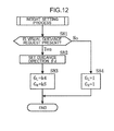
- FIG. 12 is a flowchart of a weight setting process.
- FIGS. 1 to 12 A first embodiment of the present invention will be described below with reference to FIGS. 1 to 12 .
- a sound effect generation apparatus 1 selectively generates sound effects (a harmonic sound, a rumble sound, and a discord) of an engine in accordance with a running state of the vehicle V, and differently uses tones of the sound effects of the engine in accordance with the running state.
- the sound effect generation apparatus 1 provides current and future running information to a driver (a vehicle occupant) through an acoustic sense. In such a manner, an acoustic presentation effect during driving is heightened.
- a sound effect presentation function provided by the sound effect generation apparatus 1 includes a realism enhancing function, a reminder function, and an operation uncomfortable feeling alleviating function.
- the harmonic sound is a sound effect obtained by synthesizing a fundamental wave sound having a fundamental frequency component with an integer-order adjustment wave sound having an integer-order frequency component of the fundamental wave sound.
- the rumble sound is a sound effect obtained by synthesizing a fundamental wave sound having a fundamental frequency component with a half-order adjustment wave sound having a half-order frequency component of the fundamental wave sound.
- the discord is a sound effect obtained by synthesizing a fundamental wave sound having a fundamental frequency component with a discordant adjustment wave sound having a discordant frequency component other than the integer-order frequency component and the half-order frequency component of the fundamental wave sound.
- a primary frequency component is the fundamental frequency component
- a primary component wave sound having the primary frequency component is the fundamental wave sound.
- the sound effect generation apparatus 1 includes an electric control unit (ECU) 2 , a pair of right and left speakers 3 and 4 used as a part of an audio system, an accelerator sensor 5 , a yaw rate sensor 6 , a steering angle sensor 7 , a lateral acceleration sensor (hereinafter, referred to as a lateral G sensor) 8 , a wheel speed sensor 9 , a gradient sensor 10 , a weight sensor 11 , a navigation device 12 , a turn control device (hereinafter, referred to as a DSC device) 13 , a drive assist device 14 , a mode selector switch 15 (mode selector unit), and the like.
- ECU electric control unit
- the pair of speakers 3 and 4 is connected so as to be capable of receiving an electric signal from the ECU 2 .
- the respective sensors 5 to 11 and the mode selector switch 15 are connected so as to be capable of transmitting an electric signal to the ECU 2 .
- the respective devices 12 to 14 are connected so as to be capable of transmitting and receiving an electric signal to and from the ECU 2 .
- At least one of the respective sensors 5 to 11 and the respective devices 12 to 14 corresponds to a running state detecting unit that directly or indirectly detects a running state of the vehicle V including running environment information of the vehicle V.
- the pair of speakers 3 and 4 and the respective sensors 5 to 11 will be first described.
- the pair of speakers 3 and 4 is disposed on lower end portions of a pair of right and left front pillars, respectively, in accordance with a left front position and a right front position of a driver sat on a front seat.
- the speakers 3 and 4 are configured to be capable of independently changing respective frequency gains and sound pressure levels of sounds (sound effects) generated by an operation signal input from the ECU 2 .
- a driver's visual line is guided toward the speaker 3 . Therefore, the driver can be caused to recognize a left front visual field including a left door mirror.
- a driver's visual line is guided toward the speaker 4 . Therefore, the driver can be caused to recognize a right front visual field including a right door mirror.
- the accelerator sensor 5 detects a pressing-down amount of an accelerator pedal (not illustrated) and outputs a detection signal.
- the yaw rate sensor 6 outputs a signal according to a yaw rate y of the vehicle V.
- the steering angle sensor 7 outputs a signal relating to a steering angle ⁇ of a steering wheel operated by a driver.
- the lateral G sensor 8 outputs a signal relating to a current lateral acceleration A which acts on the vehicle V.
- the wheel speed sensor 9 outputs a signal according to a rotation speed of wheels (not illustrated) for detection of a vehicle speed v.
- the gradient sensor 10 outputs a signal according to an inclination angle of a driving lane (road surface) on which the vehicle V currently runs or stops.
- the weight sensor 11 outputs a signal relating to a weight of a load in a trunk of the vehicle V.
- the navigation device 12 is disposed on an upper center of an instrument panel, and includes a position detector for the vehicle V, a map data input unit, a sound output speaker, a monitor, and the like (they are not illustrated).
- the navigation device 12 is electrically connected with a global positioning system (GPS) receiver (not illustrated) for detecting a current running position of the vehicle V.
- GPS global positioning system
- the GPS receiver receives signals from a plurality of GPS satellites to detect a current position of the vehicle V.
- the navigation device 12 includes a map database in which road map data is stored, traffic rules database in which traffic rules data is stored, and the like (these databases are not illustrated).
- the navigation device 12 gives a driver a route to driver's destination using the current position data of the vehicle V through the GPS receiver, the road map data in the map database, and the traffic rules data in the traffic rules database.
- the navigation device 12 outputs the current position data of the vehicle V, the road map data, and the traffic rules data to the ECU 2 .
- the navigation device 12 corresponds to a turn information acquisition unit that acquires curvature information including an existence position and a turning radius of a curve on a driving lane in a traveling frontal direction of the vehicle V from the map database.
- the DSC device 13 receives input signals from the respective sensors to perform DSC control to improve running stability of the vehicle V during turn.
- the DSC device 13 controls braking forces of the respective wheels through an operation of a pressurizing unit (not illustrated) for a brake fluid pressure, and causes a yaw moment to act on a vehicle body so as to turn the turning attitude of the vehicle V in a target direction.
- the DSC device 13 receives the input signals from the respective sensors, and performs antilock brake system (ABS) control to prevent wheel locks of the respective wheels.
- ABS antilock brake system
- the DSC device 13 calculates slip ratios of the respective wheels based on a detection signal from the wheel speed sensor 9 , and when detecting a wheel whose calculated slip ratio exceeds a predetermined threshold, controls the pressurizing unit to reduce the braking force acting on the wheel detected. In such a manner, the wheel lock is prevented.
- the DSC device 13 calculates, based on a detection signal from the lateral G sensor 8 and a detection signal from the wheel speed sensor 9 , a road surface friction coefficient ⁇ (hereinafter, simply the friction coefficient ⁇ ) as well as the slip ratios of the wheels, and outputs the calculated friction coefficient ⁇ to the ECU 2 .
- the drive assist device 14 has an inter-vehicle distance notifying function of notifying an inter-vehicle distance in front of and behind the vehicle V, a feeling improving function of improving driver's feeling, and the like.
- the inter-vehicle distance notifying function is a function of avoiding collision by sounding an alarm via the speakers 3 and 4 or lighting a warning lamp (not illustrated) so as to cause a driver to recognize a risk of collision when another vehicle (a leading vehicle or a following vehicle) or an obstacle is present in a region which is separated from the vehicle V by a predetermined distance in front of and behind the vehicle V during running, and by guiding the driver to perform an avoiding operation.
- the feeling improving function is a function of estimating a feeling relating to driver's emotions during running, based on driver's facial expression and action, and guiding a driver's feeling to an improved zone (from an uncomfortable or inactive state to a comfortable or active state) through lighting and music.
- the drive assist device 14 includes charge coupled device (CCD) cameras 16 to 18 that can capture a still image or a moving image.
- CCD charge coupled device
- the front camera 16 is attached to a position near a rear-view mirror (not illustrated) on a front-end lower surface of a roof panel, and is configured to be capable of imaging a white line position of a driving lane in a traveling frontal direction, a leading vehicle, approach and parting positions of a curve in the traveling frontal direction, and the like, via a front windshield glass.
- the rear camera 17 is attached to a rear-end lower surface of the roof panel, and is configured to be capable of imaging a following vehicle and the like via a rear windshield glass.
- the cameras 16 and 17 are a stereo type camera in which a lens mechanism and a shutter mechanism are shared by the two cameras, and are configured to be capable of individually detecting a distance between the vehicle V and an object to be imaged and a direction from the vehicle V to the object to be imaged.
- the indoor camera 18 is attached, for example, to above the instrument panel to image an upper body of the driver including a driver's face.
- the captured image of the upper body of the driver is used for: specifying a facial expression by cutting out the facial image from the captured image; specifying a dimension of pupils and an eye direction by enlarging and detecting irises of eyes; and specifying an attitude based on a barycentric position of the image and a shape of the upper body, for example.
- a driver's emotion is estimated by using a biaxial plane formed by a transverse axis expressing comfort and discomfort and a vertical axis expressing activeness and inactiveness (for example, a Russell's circumplex model of emotions) and a feature amount of a driver's facial expression imaged by the indoor camera 18 .
- the indoor camera 18 can capture an indoor image including a vehicle occupant (passenger) other than the driver at a wide angle, and detects the number of vehicle occupants in the vehicle V through this captured image.
- the mode selector switch 15 includes a momentary selector switch with which activation (starting of an operation) of the sound effect generation apparatus 1 and a type (a mode) of a sound effect can be selected.
- the mode selector switch 15 is configured to be capable of selecting a first mode for generating an engine sound effect mainly including a harmonic sound through a predetermined ON operation, or a second mode for generating an engine sound effect mainly including a rumble sound through a predetermined ON operation.
- a driver a vehicle occupant
- a rumble sound which is obtained by synthesizing the fundamental wave sound with one or more half-order adjustment wave sounds, is rather dynamic.
- a quasi-concord that causes the vehicle occupants such as the driver to recognize feeling of power is generated.
- a third mode for generating an engine sound effect mainly including a discord is executed under a condition that a risk degree B determined by a risk degree determining unit 25 , described later, is a determination threshold r 1 or more for determining the risk degree.
- the sound effect to be generated in the third mode is obtained by synthesizing a fundamental wave sound having a fundamental frequency component with one or more discordant adjustment wave sounds having a discordant frequency component other than an integer-order frequency component and a half-order frequency component of the fundamental wave sound. For this reason, a beat occurs between component sounds. Thus, this sound effect is a discord that gives the driver an uncomfortable impression accompanied by nervousness and a sense of caution.
- the ECU 2 will be described below.
- the ECU 2 is configured to synthesize a fundamental wave sound with the selected one or more adjustment wave sounds to artificially generate an engine sound effect so as to improve a driver's operational feeling.
- the ECU 2 includes a central processing unit (CPU), a read-only memory (ROM), a random-access memory (RAM), an amplifier, an in-side interface, and an out-side interface.
- CPU central processing unit
- ROM read-only memory
- RAM random-access memory
- amplifier an in-side interface
- out-side interface an out-side interface
- the ROM stores various programs and data for generating respective engine sound effects
- the RAM is provided with a processing area to be used when the CPU executes a series of process.
- the in-side interface is electrically connected to the respective sensors 5 to 11 , the respective devices 12 to 14 , and the mode selector switch 15 .
- the out-side interface is electrically connected to the pair of speakers 3 and 4 and the respective devices 12 to 14 via the amplifier.
- the ECU 2 stores, for example, a vibration sound map M 1 (a vibration sound database) in which a plurality of sound sources is stored, the sound sources being preset so as to be fitted to generated sounds from a four-cylinder gasoline engine mounted to the vehicle V.
- a vibration sound map M 1 a vibration sound database
- the sound sources being preset so as to be fitted to generated sounds from a four-cylinder gasoline engine mounted to the vehicle V.
- the vibration sound map M 1 stores, per rotation speed of an engine, sound sources at each unit frequency (for example, 0.01-order frequency) from a primary component wave sound (a fundamental wave sound) to 10-order component wave sound, the primary component wave sound having a fundamental frequency component, the 10-order component wave sound having a frequency component which is ten times as large as the fundamental frequency component.
- unit frequency for example, 0.01-order frequency
- the vibration sound map M 1 includes, per rotation speed of an engine, a fundamental wave sound, an integer-order component wave sound (an integer-order adjustment wave sound) having a frequency component which is an integral multiple of a fundamental frequency component, a half-order component wave sound (a half-order adjustment wave sound) in which an even-number-order overtone is an overtone series of the fundamental wave sound, and a discordant component wave sound (a discordant adjustment wave sound) in which an overtone relationship does not hold with respect to the fundamental wave sound.
- an integer-order component wave sound an integer-order adjustment wave sound having a frequency component which is an integral multiple of a fundamental frequency component
- a half-order component wave sound a half-order adjustment wave sound
- a discordant component wave sound a discordant adjustment wave sound
- the ECU 2 includes a lateral input amount setting unit 21 , an adjustment wave sound selector 22 , a behavior delay predicting unit 23 , an inhibition condition determining unit 24 , a risk degree determining unit 25 , a lateral G calculating unit 26 (a lateral acceleration calculating unit), a sound effect generation unit 27 , and a visual guidance direction setting unit 28 .
- the lateral input amount setting unit 21 is configured to be capable of setting a lateral input amount P in which a physical amount relating to at least one of a movement of the vehicle V in a width direction and a movement of the vehicle V in the turning direction is a parameter, based on a running state of the vehicle V detected by a running state detecting unit (at least one of the respective sensors 5 to 11 and the respective devices 12 to 14 ).
- the lateral input amount setting unit 21 sets the lateral input amount P to the lateral acceleration A.
- the vehicle speed v is low like a time of turning right or left at an intersection, since sideslip or slip of the vehicle V hardly occurs, the lateral acceleration A in which an actual turning state of the vehicle V is reflected most clearly is used as the lateral input amount P.
- At least a vehicle state in a lateral direction may be reflected in the lateral input amount P.
- any one detection value of the steering angle ⁇ of the steering wheel, the yaw rate y, and the lateral acceleration A may be used as the lateral input amount P regardless of the vehicle speed v.
- a parameter in which two or more detection values are combined can be adopted as the lateral input amount P regardless of the vehicle speed v.
- the adjustment wave sound selector 22 will be described below.
- the adjustment wave sound selector 22 is configured to be capable of selecting, from the plurality of component wave sounds stored in the vibration sound map M 1 , one or more adjustment wave sounds to be synthesized with a fundamental wave sound N 0 .
- the adjustment wave sound selector 22 selects first to third adjustment wave sounds N 1 to N 3 , and determines, using the gain maps M 2 to M 4 selected based on a running state, first to third gains g 1 to g 3 (0 ⁇ g 1 ⁇ g 2 ⁇ g 3 ) for correcting the first to third adjustment wave sounds N 1 to N 3 , respectively.
- the gain maps M 2 to M 4 will be described.
- the ECU 2 stores a standard gain map M 2 , a decrease gain map M 3 , an increase gain map M 4 in advance.
- Gains ⁇ 2 to ⁇ 4 , ⁇ 2 to ⁇ 4 , and ⁇ 2 to ⁇ 4 of the first to third adjustment wave sounds N 1 to N 3 as one of output properties of a sound effect are set symmetrically so as to be defined to zero when the lateral acceleration A is zero and so as to be increased like a linear function as an absolute value of the lateral acceleration A increases.
- the gains ⁇ 2 to ⁇ 4 , ⁇ 2 to ⁇ 4 , and ⁇ 2 to ⁇ 4 increase at an increase rate which is larger than an increase rate before a certain mid-stage point and are converged to a constant value at an upper limit value.
- the gain values are defined such that a following formula (2) holds. ⁇ 2 ⁇ 2 ⁇ 2 ⁇ 3 ⁇ 3 ⁇ 3 ⁇ 4 ⁇ 4 ⁇ 4 (2)
- the gain values are defined respectively such that a following formula (3) holds. ⁇ 3 ⁇ 2 ⁇ 4 ⁇ 3 ⁇ 2 ⁇ 4 ⁇ 3 ⁇ 2 ⁇ 4 (3)
- the adjustment wave sound selector 22 selects the gain maps M 2 to M 4 using, as determination conditions, a predicted result of the behavior delay predicting unit 23 and a determined result of the inhibition condition determining unit 24 .
- the behavior delay predicting unit 23 is configured to predict that a behavior delay of the vehicle V occurs when a total weight of the vehicle V to be specified by the number of vehicle occupants and a weight of a cargo (hereinafter, simply a vehicle weight) is a determination threshold t 3 or more.
- the adjustment wave sound selector 22 selects the increase gain map M 4 having high responsivity.
- the adjustment wave sound selector 22 selects the increase gain map M 4 having high responsivity such that a sound effect is corrected to be increased prior to a current behavior of the vehicle V.
- the behavior delay of the vehicle V is corrected acoustically so that a driver's feeling of strangeness in the operation can be eliminated.
- the inhibition condition determining unit 24 is configured to determine that the vehicle V is in a condition that association between a driver's operation amount and the behavior of the vehicle V is inhibited, in other words, operability of the vehicle V is deteriorated (hereinafter, in the inhibition condition), when the friction coefficient ⁇ is a determination threshold t 4 or less or when an ascending gradient is a determination threshold t 5 or more.
- the adjustment wave sound selector 22 selects the decrease gain map M 3 having low responsivity.
- the adjustment wave sound selector 22 selects the decrease gain map M 3 having low responsivity such that the sound effect is corrected to be decreased. As a result, degradation of the following performance of the vehicle V is corrected acoustically so that a driver's feeling of strangeness in the operation can be eliminated.
- the standard gain map M 2 having standard responsivity is selected.
- the adjustment wave sound selector 22 is configured to select, based on the lateral input amount P, the first to third adjustment wave sounds N 1 to N 3 having an integer-order frequency component.
- a secondary component wave sound which is an integer-order frequency component closest to a fundamental frequency component is allocated to the first adjustment wave sound N 1 .
- a tertiary component wave sound which is an integer-order frequency component next closest after the secondary component wave sound is allocated to the second adjustment wave sound N 2 as well as the already selected first adjustment wave sound N 1 .
- a quaternary component wave sound which is an integer-order frequency component next closest after the tertiary component wave sound is allocated to the third adjustment wave sound N 3 as well as the already selected first and second adjustment wave sounds N 1 and N 2 .
- the reason for such an operation is that a consonance level of an adjustment wave sound having an integer-order frequency component can be made to be higher as the integer-order frequency component is closer to the fundamental frequency component.
- the adjustment wave sound selector 22 extracts, based on the lateral input amount P, the gain g 1 ( ⁇ 2 to ⁇ 4 ) for correcting the first adjustment wave sound N 1 , the gain g 2 ( ⁇ 2 to ⁇ 4 ) for correcting the second adjustment wave sound N 2 , and the gain g 3 ( ⁇ 2 to ⁇ 4 ) for correcting the third adjustment wave sound N 3 from any one of the selected gain maps M 2 to M 4 .
- the adjustment wave sound selector 22 increases the number of the first to third adjustment wave sounds N 1 to N 3 and increases the first to third gains g 1 to g 3 of the selected first to third adjustment wave sounds N 1 to N 3 .
- the adjustment wave sound selector 22 is configured to select, based on the lateral input amount P, the first to third adjustment wave sounds N 1 to N 3 having a half-order frequency component when the second mode is selected.
- a 1.5-order component wave sound which is a half-order frequency component closest to a fundamental frequency component is allocated to the first adjustment wave sound N 1 .
- a 2.5-order component wave sound which is a half-order frequency component next closest after the 1.5-order component wave sound is allocated to the second adjustment wave sound N 2 as well as the already selected first adjustment wave sound N 1 .
- a 3.5-order component wave sound which is a half-order frequency component next closest after the 2.5-order component wave sound is allocated to the third adjustment wave sound N 3 as well as the already selected first and second adjustment wave sounds N 1 and N 2 .
- a consonance level (a quasi-concordant level) of an adjustment wave sound having a half-order frequency component can be made to be higher as the half-order frequency component is closer to the fundamental frequency component.
- the adjustment wave sound selector 22 extracts, based on the lateral input amount P, the gain g 1 for correcting the first adjustment wave sound N 1 , the gain g 2 for correcting the second adjustment wave sound N 2 , and the gain g 3 for correcting the third adjustment wave sound N 3 from any one of the selected gain maps M 2 to M 4 .
- the adjustment wave sound selector 22 increases the number of the first to third adjustment wave sounds N 1 to N 3 and increases the first to third gains g 1 to g 3 of the selected first to third adjustment wave sounds N 1 to N 3 .
- the adjustment wave sound selector 22 is configured to select, based on the risk degree B, the first to third adjustment wave sounds N 1 to N 3 having a discordant frequency component when the third mode is selected in accordance with the determination in the risk degree determining unit 25 .
- the risk degree determining unit 25 determines the risk degree B of the vehicle V based on a current running state.
- the risk degree determining unit 25 calculates determination amounts a to c based on a steering angle speed ⁇ in a driver's steering operation, the lateral input amount P, and an inter-vehicle distance L between the vehicle V and a leading vehicle or a following vehicle closest to the vehicle V, and calculates the risk degree B based on the calculated determination amounts a to c.
- the steering angle speed determination amount a is calculated in accordance with a following formula (4).
- the amount a is zero.
- the lateral input amount determination amount b is calculated in accordance with a following formula (5).
- the inter-vehicle distance determination amount c is calculated in accordance with a following formula (6).
- the risk degree B is calculated in accordance with a following formula (7).
- B a+b+c (7)
- the adjustment wave sound selector 22 determines that the third mode is selected and selects the first to third adjustment wave sounds N 1 to N 3 based on the risk degree B.
- a 9.75-order component sound wave is allocated to the first adjustment wave sound N 1 , the 9.75-order component sound wave being a discordant frequency component which is farthest from the fundamental frequency component and is in a middle section between an integer-order frequency component (a ten-order frequency component) and a half-order frequency component (a 9.5-order frequency component).
- a 9.25-order component sound wave is allocated to the second adjustment wave sound N 2 as well as the already selected first adjustment wave sound N 1 , the 9.25-order component sound wave being a discordant frequency component which is next farthest from the fundamental frequency component after the 9.75-order component sound wave and is in a middle section between an integer-order frequency component (a 9-order frequency component) and the half-order frequency component (the 9.5-order frequency component).
- a 8.75-order component wave sound is allocated to the third adjustment wave sound N 3 as well as the already selected first and second adjustment wave sounds N 1 and N 2 , the 8.75-order component wave sound being a discordant frequency component which is next farthest from fundamental frequency after the 9.25-order component sound wave and is in a middle section between the integer-order frequency component (the 9-order frequency component) and a half-order frequency component (a 8.5-order frequency component).
- the reason for such an operation is that interference increases and a discordant level can be made to be higher in the adjustment wave sound having the discordant frequency component as the discordant frequency component is farther from the fundamental frequency component and is farther from the integer-order frequency component and the half-order frequency component.
- the adjustment wave sound selector 22 extracts, based on the lateral input amount P, the gain g 1 for correcting the first adjustment wave sound N 1 , the gain g 2 for correcting the second adjustment wave sound N 2 , and the gain g 3 for correcting the third adjustment wave sound N 3 from any one of the selected gain maps M 2 to M 4 , and corrects the first to third adjustment wave sounds N 1 to N 3 .
- the adjustment wave sound selector 22 increases the number of the first to third adjustment wave sounds N 1 to N 3 to be selected and increases the first to third gains g 1 to g 3 of the selected first to third adjustment wave sounds N 1 to N 3 .
- the adjustment wave sound selector 22 selects the first to third adjustment wave sounds N 1 to N 3 , and determines, using the gain maps M 2 to M 4 selected based on the running state, the first to third gains g 1 to g 3 for respectively correcting the first to third adjustment wave sounds N 1 to N 3 .
- the lateral G calculating unit 26 is configured to determine, based on map information including a turning radius input from the map database of the navigation device 12 , whether a curve is present in the traveling frontal direction of the vehicle V, and to calculate, when the curve is present, the prediction lateral acceleration A 1 , which acts on the vehicle V going around the curve.
- the prediction lateral acceleration A 1 is calculated under a condition that a curve is present at a distance which has been preset so as to be separated from a current running position of the vehicle V or in an area where the vehicle V has been predicted to arrive within a preset time.
- a turning angle ⁇ t of the wheels can be calculated in accordance with a following formula (8) when a prediction steering angle of the vehicle V according to the turning radius of the curve is represented by ⁇ p and a gear ratio of the vehicle V is represented by gr.
- ⁇ t ⁇ p/gr (8)
- a front wheel position rotating radius R of the vehicle V can be calculated in accordance with a following formula (9) when a wheel base of the vehicle V is represented by W.
- R W /sin ⁇ t (9)
- the prediction lateral acceleration A 1 can be expressed by a following formula (10). For this reason, the prediction lateral acceleration A 1 , which acts on the vehicle V in going around the curve where the vehicle V runs in the near future, can be obtained by assigning the front wheel position rotating radius R calculated in accordance with the formula (9) to the formula (10).
- a 1 v 2 /R (10)
- the sound effect generation unit 27 will be described below.
- the sound effect generation unit 27 is configured to correct, as expressed in a following formula (11), the first to third adjustment wave sounds N 1 to N 3 using the first to third gains g 1 to g 3 extracted for each mode, and synthesize the fundamental wave sound N 0 with the first to third adjustment wave sounds N 1 to N 3 corrected after selection to generate a sound effect S.
- the sound effect generation unit 27 increases a sound pressure level of the sound effect S as the lateral input amount P is larger, the risk degree B is larger, and the prediction lateral acceleration A 1 is larger.
- the driver is caused to acoustically recognize levels of the lateral input amount P, the risk degree B, and the prediction lateral acceleration A 1 which affect running of the vehicle V.
- the sound effect generation unit 27 is configured to be capable of setting the sound pressure level correction coefficients G L and G R of the pair of speakers 3 and 4 and changing the sound pressure levels of the sound effects independently.
- the sound effect generation unit 27 increases a sound pressure level of the speaker 3 (4) on a side of the visual guidance direction, the sound pressure level being set by the visual guidance direction setting unit 28 , and decreases a sound pressure level of the other speaker 4 (3) with respect to a visual guidance direction ⁇ d.
- a strength ratio between the sound pressure level correction coefficients G L and G R is changed by setting the sound pressure level correction coefficients G L and G R for correction coefficients k 4 and k 5 , respectively, and a localized horizontal direction of a sound image with respect to a frontal direction of the driver is changed.
- the correction coefficients k 4 and k 5 are obtained as interpolation coefficients to be set based on the visual guidance direction ⁇ d.
- the visual guidance direction setting unit 28 is configured to determine presence or absence of a visual guidance request based on various information from the navigation device 12 and the drive assist device 14 , and be capable of setting, when the visual guidance request is present, the visual guidance direction ⁇ d at which the driver shoots a look in a frontal direction of the driver.
- a subject at which the driver has to look is a subject that possibly affects running of the vehicle V from a viewpoint of safety and operability when the driver does not recognize the subject.
- the visual guidance direction ⁇ d is defined as a direction where the driver can recognize a subject at which the driver has to look with the driver as a reference.
- the visual guidance direction setting unit 28 determines presence of the visual guidance request to guide the driver's visual line to a right door mirror. For this reason, the visual guidance direction ⁇ d associated with a right forward direction is set, and sound images from the speakers 3 and 4 are localized in the visual guidance direction ⁇ d.
- the visual guidance direction setting unit 28 determines presence of the visual guidance request, and sets the visual guidance direction ⁇ d associated with a curve parting position to localize sound images from the speakers 3 and 4 in the visual guidance direction ⁇ d.
- the visual guidance direction setting unit 28 determines presence of the visual guidance request, and sets the visual guidance direction ⁇ d associated with a rest area (or an overhead sign) based on the map information in the navigation device 12 to localize the sound images from the speakers 3 and 4 in the visual guidance direction ⁇ d.
- the process goes to S 8 and a weight setting process is executed.
- a signal of the left sound effect S L is set by multiplying the sound effect S and the sound pressure level correction coefficient G L
- a signal of the right sound effect S R is set by multiplying the sound effect S and the sound pressure level correction coefficient G R .
- the process then goes to S 10 .
- the control signals of the sound effect S L and S R are output to the speakers 3 and 4 , respectively, and after the sound effects S L and S R are generated from the speakers 3 and 4 , respectively, the process returns.
- S 15 a determination is made whether the first mode has been selected by an operation of the mode selector switch 15 .
- the 9.75-order component sound wave which is the discordant frequency component is set to the first adjustment wave sound N 1 , and the process goes to S 53 without setting the second and third adjustment wave sounds N 2 and N 3 (in this case, N 2 and N 3 are zero, the same below).
- the gain g 1 (g 2 , g 3 ) of the adjustment wave sound N 1 (N 2 , N 3 ) set in the previous step is set based on the gain map selected in the map selecting process.
- the process then goes to S 54 , and a multiplied value of the risk degree B by a correction coefficient f 2 is set as the sound pressure level correction coefficient F.
- a multiplied value which is obtained by multiplying an added value of the first adjustment wave sound N 1 corrected by the gain g 1 , the second adjustment wave sound N 2 corrected by the gain g 2 , and the third adjustment wave sound N 3 corrected by the gain g 3 , by the sound pressure level correction coefficient F, is set to the sound effect S. The process then ends.
- the 9.75-order component sound wave is set to the first adjustment wave sound N 1
- the 9.25-order component sound wave which is discordant frequency component is set to the second adjustment wave sound N 2 .
- the process goes to S 53 without setting the third adjustment wave sound N 3 .
- the 9.75-order component sound wave is set to the first adjustment wave sound N 1
- the 9.25-order component sound wave is set to the second adjustment wave sound N 2
- the 8.75-order component wave sound which is the discordant frequency component is set to the third adjustment wave sound N 3 . Thereafter, the process goes to S 53 .
- the secondary component wave sound which is the integer-order frequency component is set to the first adjustment wave sound N 1 , and the process goes to S 63 without setting the second and third adjustment wave sounds N 2 and N 3 .
- the gain g 1 (g 2 , g 3 ) of the adjustment wave sound N 1 (N 2 , N 3 ) set in the previous step is set based on the gain map selected in the map selecting process.
- the process then goes to S 64 , and a determination is made whether the sound pressure level correction coefficient F has already been set.
- a multiplied value which is obtained by multiplying an added value of the first adjustment wave sound N 1 corrected by the gain g 1 , the second adjustment wave sound N 2 corrected by the gain g 2 , and the third adjustment wave sound N 3 corrected by the gain g 3 , by the sound pressure level correction coefficient F, is set to the sound effect S. The process then ends.
- the secondary component wave sound is set to the first adjustment wave sound N 1
- the tertiary component wave sound which is the integer-order frequency component is set to the second adjustment wave sound N 2 .
- the process goes to S 63 without setting the third adjustment wave sound N 3 .
- the secondary component wave sound is set to the first adjustment wave sound N 1
- the tertiary component wave sound is set to the second adjustment wave sound N 2
- the quaternary component wave sound N which is the integer-order frequency component is set to the third adjustment wave sound N 3 .
- the process then goes to S 63 .
- the 1.5-order component wave sound which is the half-order frequency component is set to the first adjustment wave sound N 1 , and the process goes to S 73 without setting the second and third adjustment wave sounds N 2 and N 3 .
- the gain g 1 (g 2 , g 3 ) of the adjustment wave sound N 1 (N 2 , N 3 ) set in the previous step is set based on the gain map selected in the map selecting process.
- the process then goes to S 74 , and a determination is made whether the sound pressure level correction coefficient F has already been set.
- a multiplied value which is obtained by multiplying an added value of the first adjustment wave sound N 1 corrected by the gain g 1 , the second adjustment wave sound N 2 corrected by the gain g 2 , and the third adjustment wave sound N 3 corrected by the gain g 3 , by the sound pressure level correction coefficient F, is set to the sound effect S. The process then ends.
- the 1.5-order component wave sound is set to the first adjustment wave sound N 1
- the 2.5-order component wave sound which is the half-order frequency component is set to the second adjustment wave sound N 2 .
- the process then goes to S 73 without setting the third adjustment wave sound N 3 .
- the 1.5-order component wave sound is set to the first adjustment wave sound N 1
- the 2.5-order component wave sound is set to the second adjustment wave sound N 2
- the 3.5-order component wave sound which is the half-order frequency component is set to the third adjustment wave sound N 3 .
- the process then goes to S 73 .
- the visual guidance direction setting unit 28 determines in S 81 whether the visual guidance request is present.
- the process then goes to S 83 , and the sound pressure level correction coefficients G L and G R are set to the correction coefficients k 4 and k 5 , respectively, based on the visual guidance direction ⁇ d. Thereafter, the process ends.
- the sound pressure level correction coefficients G L and G R are set to 1, and the process ends.
- the sound effect generation apparatus 1 includes the lateral input amount setting unit 21 that sets, based on the running state detected by the sensors 6 and 8 , the lateral input amount P in which a physical amount relating to at least one of a movement of the vehicle V in the width direction and a movement of the vehicle V in the turning direction is a parameter. For this reason, the lateral input amount P in which an actual turning behavior of the vehicle V is reflected can be set regardless of an operating amount of the vehicle V by the driver.
- the sound effect generation apparatus 1 includes the adjustment wave sound selector 22 that can select, based on the lateral input amount P, the first to third adjustment wave sounds N 1 to N 3 having a half-order frequency component. For this reason, it is possible to select the first to third adjustment wave sounds N 1 to N 3 (half-order adjustment wave sounds) that can generate rumble sounds for causing the driver to recognize dynamism as a quasi-concord. Further, the sound effect generation apparatus 1 includes the sound effect generation unit 27 that synthesizes the fundamental wave sound N 0 with the selected first to third adjustment wave sounds N 1 to N 3 . For this reason, the rumble sound adaptable to an actual turning behavior of the vehicle V is generated so that driver's operational feeling can be heightened.
- the adjustment wave sound selector 22 increases the gains g 1 to g 3 of the selected half-order adjustment wave sounds N 1 to N 3 as the lateral input amount P is larger. For this reason, feeling of power to be recognized by the driver can be enhanced.
- the adjustment wave sound selector 22 selects, from the half-order component wave sounds included in the vibration sound map M 1 , at least a half-order adjustment wave sound N 1 having a half-order frequency component closest to the fundamental frequency component. For this reason, interference with the fundamental wave sound N 0 can be suppressed, and a rumble sound which is both comfortable and powerful can be generated.
- the sound effect generation unit 27 increases the sound pressure level of the sound effect S as the lateral input amount P is larger. Therefore, feeling of power to be recognized by the driver can be further enhanced according to the turning behavior of the vehicle V.
- the adjustment wave sound selector 22 is configured to be capable of selecting the first to third adjustment wave sounds N 1 to N 3 having an integer-order frequency component, based on the lateral input amount P.
- the sound effect generation unit 27 is configured to be capable of synthesizing the fundamental wave sound N 0 with the selected first to third adjustment wave sounds N 1 to N 3 (the integer-order adjustment wave sounds).
- the sound effect generation apparatus 1 includes the mode selector switch 15 that can select the first mode and the second mode, the first mode being for selecting integer-order adjustment wave sounds as the first to third adjustment wave sounds N 1 to N 3 and synthesizing the integer-order adjustment wave sounds with the fundamental wave sound NO, the second mode being for selecting half-order adjustment wave sounds as the first to third adjustment wave sounds N 1 to N 3 and synthesizing the half-order adjustment wave sounds with the fundamental wave sound N 0 .
- the number of adjustment wave sounds to be synthesized with a fundamental wave sound can be set to at most 3 based on a running state, but the number of the adjustment wave sounds may be set to 2 or 4 or more according to a specification, a running environment, and a state of the vehicle V.
- the number of gains defined in the gain maps M 2 to M 4 is preferably set according to the number of set adjustment wave sounds.
- an adjustment wave sound to be synthesized with a fundamental wave sound is limited to a half-order adjustment wave sound, but the adjustment wave sound may be selected to include an integer-order adjustment wave sound having an integer-order frequency component close to one or more half-order adjustment wave sounds selected.
- a 2.5-order component wave sound is synthesized with a fundamental wave sound (a primary component wave sound)
- a secondary component wave sound or a tertiary component wave sound closest to the 2.5-order component wave sound is additionally synthesized so that a rumble sound that provides enhanced comfortableness can be generated.
- the sound effect generation unit changes the sound pressure levels of the pair of right and left speakers so that the localized direction of a sound image is changed.
- the localized direction of a sound image may be changed by setting a delay time of a sound effect to reach the driver while the sound pressure levels of the pair of speakers are maintained without changing the sound pressure levels of the pair of speakers.
- an output from the speaker on a side opposite to the visual guidance direction is delayed from an output from the visual guidance direction-side speaker, so that the localized direction of a sound image can be moved toward the visual guidance direction.
- the localized direction of a sound image may be shifted linearly from the frontal direction of the driver through the visual guidance direction, and this shifting operation may be repeated.
- speakers may be movable.
- a speaker may be additionally disposed above the pair of speakers so that the visual guidance direction can be set three-dimensionally.
- the above embodiment has described an example of the drive assist device having the inter-vehicle distance notifying function and the feeling improving function.
- the drive assist device can detect at least an outside-vehicle situation and an in-vehicle situation, and thus may have an obstacle detecting function or a white line (of a driving lane) detecting function.
- detecting means may be means other than a CCD, and thus may be, for example, a millimeter-wave radar.
- the above embodiment has described an example of the sound effect generation apparatus that generates a sound effect of an engine based on a lateral input amount that affects a movement of the vehicle in the width direction.
- the sound effect generation apparatus may generate a sound effect of an engine based on at least the lateral input amount. Therefore, a sound effect generation apparatus that generates a sound effect of an engine based on an accelerator opening degree may be used in combination.
- cooperative control is enabled by the sound effect generation apparatus that generates a sound effect of an engine based on an accelerator opening degree.
- a vibration sound map may be prepared for each engine specification such as displacement or the number of cylinders so that a vibration sound map according to an engine specification can be selected when a mounted engine is replaced.
- a sound effect may be generated by using a vibration sound map of any internal combustion (for example, a four-cylinder gasoline engine) for a hybrid vehicle or an electric vehicle.
- the above embodiment relates to a vehicle sound effect generation apparatus for generating a sound effect of an engine based on a vibration sound database including a fundamental wave sound having a fundamental frequency component and a plurality of adjustment wave sounds having a frequency component other than the fundamental frequency component.
- the vehicle sound effect generation apparatus includes a running state detecting unit that detects a running state of a vehicle, a lateral input amount setting unit that sets, based on the running state detected by the running state detecting unit, a lateral input amount in which a physical amount relating to at least one of a movement of the vehicle in a width direction and a movement of the vehicle in a turning direction is a parameter, an adjustment wave sound selector that selects one or more half-order adjustment wave sounds having a half-order frequency component, based on the lateral input amount, and a sound effect generation unit that synthesizes the fundamental wave sound with the one or more half-order adjustment wave sounds selected.
- the vehicle sound effect generation apparatus includes the lateral input amount setting unit that sets, based on the running state detected by the running state detecting unit, the lateral input amount in which a physical amount relating to at least one of the movement of the vehicle in the width direction and the movement of the vehicle in the turning direction is a parameter. For this reason, a lateral input amount in which an actual turning behavior of the vehicle is reflected can be set regardless of an operation amount of the vehicle operated by a vehicle occupant.
- the vehicle sound effect generation apparatus includes the adjustment wave sound selector that selects the one or more half-order adjustment wave sounds having a half-order frequency component, based on the lateral input amount. For this reason, it is possible to select a half-order adjustment wave sound, which enables generation of a rumble sound for causing a vehicle occupant to recognize dynamics. Further, the vehicle sound effect generation apparatus includes the sound effect generation unit that synthesizes the fundamental wave sound with the one or more half-order adjustment wave sounds selected. For this reason, a rumble sound adaptable to an actual turning behavior of the vehicle is generated so that operational feeling of the vehicle occupant can be heightened.
- the half-order adjustment wave sound having the half-order frequency component an even-number-order overtone is an overtone series of the fundamental wave sound, interference partially occurs with respect to the fundamental wave sound.
- a vehicle occupant feels such interference only slightly. Therefore, the rumble sound obtained by synthesizing the fundamental wave sound with the half-order adjustment wave sound can be treated as a quasi-concord that might cause a vehicle occupant to sensationally recognize dynamics while the vehicle is being driven.
- the adjustment wave sound selector increases, as the lateral input amount is larger, a gain or gains of the one or more half-order adjustment wave sounds selected.
- This configuration can enhance feeling of power to be recognized by a vehicle occupant.
- the adjustment wave sound selector selects, from the half-order adjustment wave sounds included in the vibration sound database, at least a half-order adjustment wave sound having a half-order frequency component closest to the fundamental frequency component.
- This configuration can suppress interference with the fundamental wave sound and can generate a rumble sound which is both comfortable and powerful.
- the sound effect generation unit increases a sound pressure level of the sound effect as the lateral input amount is larger.
- This configuration can further enhance feeling of power to be recognized by a vehicle occupant according to a turning behavior of the vehicle.
- the adjustment wave sound selector is configured to be capable of selecting one or more integer-order adjustment wave sounds having an integer-order frequency component, based on the lateral input amount
- the sound effect generation unit is configured to be capable of synthesizing the fundamental wave sound with the one or more integer-order adjustment wave sounds.
- the vehicle sound effect generation apparatus further includes a mode selector unit that can select a first mode for synthesizing the fundamental wave sound with the one or more integer-order adjustment wave sounds, and a second mode for synthesizing the fundamental wave sound with the one or more half-order adjustment wave sounds.
- the adjustment wave sound selector is configured to be capable of selecting one or more integer-order adjustment wave sounds having an integer-order frequency component, based on the lateral input amount
- the sound effect generation unit is configured to be capable of synthesizing the fundamental wave sound with the one or more integer-order adjustment wave sounds
- the adjustment wave sound selector selects at least an integer-order adjustment wave sound having an integer-order frequency component being close to the one or more half-order adjustment wave sounds selected.
- This configuration can generate a rumble sound that provides enhanced comfortableness.
Landscapes
- Engineering & Computer Science (AREA)
- Mechanical Engineering (AREA)
- Acoustics & Sound (AREA)
- Physics & Mathematics (AREA)
- Multimedia (AREA)
- Radar, Positioning & Navigation (AREA)
- Remote Sensing (AREA)
- General Health & Medical Sciences (AREA)
- Health & Medical Sciences (AREA)
- Signal Processing (AREA)
- Audiology, Speech & Language Pathology (AREA)
- Fittings On The Vehicle Exterior For Carrying Loads, And Devices For Holding Or Mounting Articles (AREA)
- Control Of Driving Devices And Active Controlling Of Vehicle (AREA)
- Circuit For Audible Band Transducer (AREA)
Applications Claiming Priority (3)
| Application Number | Priority Date | Filing Date | Title |
|---|---|---|---|
| JP2016071382A JP6465057B2 (ja) | 2016-03-31 | 2016-03-31 | 車両用効果音発生装置 |
| JP2016-071382 | 2016-03-31 | ||
| PCT/JP2017/010341 WO2017169766A1 (ja) | 2016-03-31 | 2017-03-15 | 車両用効果音発生装置 |
Publications (2)
| Publication Number | Publication Date |
|---|---|
| US20180366103A1 US20180366103A1 (en) | 2018-12-20 |
| US10170098B1 true US10170098B1 (en) | 2019-01-01 |
Family
ID=59964325
Family Applications (1)
| Application Number | Title | Priority Date | Filing Date |
|---|---|---|---|
| US15/761,714 Active US10170098B1 (en) | 2016-03-31 | 2017-03-15 | Sound effect generation device for vehicles |
Country Status (5)
| Country | Link |
|---|---|
| US (1) | US10170098B1 (zh) |
| EP (1) | EP3419016A4 (zh) |
| JP (1) | JP6465057B2 (zh) |
| CN (1) | CN108885866B (zh) |
| WO (1) | WO2017169766A1 (zh) |
Families Citing this family (7)
| Publication number | Priority date | Publication date | Assignee | Title |
|---|---|---|---|---|
| JP7047845B2 (ja) * | 2017-08-09 | 2022-04-05 | 三菱自動車工業株式会社 | 車両用警報装置 |
| JP6986230B2 (ja) | 2018-03-08 | 2021-12-22 | マツダ株式会社 | 情報提供装置 |
| JP2019158936A (ja) * | 2018-03-08 | 2019-09-19 | マツダ株式会社 | 情報提供装置 |
| EP3657494A1 (en) | 2018-11-20 | 2020-05-27 | Alpine Electronics, Inc. | Adaptive engine sound |
| CN110782919A (zh) * | 2019-11-02 | 2020-02-11 | 朝阳聚声泰(信丰)科技有限公司 | 一种智能匹配音效风格的汽车音响系统及其实现方法 |
| JP7122405B2 (ja) * | 2021-01-22 | 2022-08-19 | 本田技研工業株式会社 | 能動型効果音発生装置 |
| KR20230069307A (ko) * | 2021-11-11 | 2023-05-19 | 현대자동차주식회사 | 전동화 차량의 사운드 발생 장치 및 방법 |
Citations (10)
| Publication number | Priority date | Publication date | Assignee | Title |
|---|---|---|---|---|
| JPH04178698A (ja) | 1990-11-13 | 1992-06-25 | Toyota Central Res & Dev Lab Inc | 波形生成装置 |
| JP2004074994A (ja) | 2002-08-21 | 2004-03-11 | Mazda Motor Corp | 車室内音制御装置 |
| JP2008013034A (ja) | 2006-07-05 | 2008-01-24 | Nissan Motor Co Ltd | 車両用刺激提示装置及び刺激提示方法 |
| JP2008025492A (ja) | 2006-07-21 | 2008-02-07 | Toyota Central Res & Dev Lab Inc | 車両制御装置 |
| US20090028353A1 (en) | 2007-07-25 | 2009-01-29 | Honda Motor Co., Ltd. | Active sound effect generating apparatus |
| US20120177214A1 (en) | 2011-01-11 | 2012-07-12 | Hera Cristian M | Vehicle engine sound enhancement |
| US20130216054A1 (en) * | 2012-02-17 | 2013-08-22 | Honda R&D Co., Ltd. | Vehicular active sound effect generating apparatus |
| US20150199955A1 (en) * | 2014-01-15 | 2015-07-16 | CloudCar Inc. | Engine sound simulation for electric vehicles |
| JP2016145885A (ja) | 2015-02-06 | 2016-08-12 | マツダ株式会社 | 車両用効果音発生装置 |
| US20170096101A1 (en) * | 2015-10-06 | 2017-04-06 | Honda Motor Co., Ltd. | Vehicle acoustic apparatus, and methods of use and manufacture thereof |
Family Cites Families (7)
| Publication number | Priority date | Publication date | Assignee | Title |
|---|---|---|---|---|
| JP3545840B2 (ja) * | 1995-06-13 | 2004-07-21 | 日立建機株式会社 | 作業機の操作用仮想音生成装置 |
| JP4126990B2 (ja) * | 2002-08-21 | 2008-07-30 | マツダ株式会社 | 車室内音制御装置 |
| JP4664116B2 (ja) * | 2005-04-27 | 2011-04-06 | アサヒビール株式会社 | 能動騒音抑制装置 |
| US8059829B2 (en) * | 2006-03-24 | 2011-11-15 | Honda Motor Co., Ltd. | Sound effect producing apparatus for vehicle |
| JP5340121B2 (ja) * | 2009-11-30 | 2013-11-13 | 三菱電機株式会社 | オーディオ信号再生装置 |
| JP5585764B2 (ja) * | 2010-03-30 | 2014-09-10 | マツダ株式会社 | 車両用発音装置 |
| CN105165029A (zh) * | 2013-04-24 | 2015-12-16 | 日产自动车株式会社 | 车辆用音响控制装置、车辆用音响控制方法 |
-
2016
- 2016-03-31 JP JP2016071382A patent/JP6465057B2/ja not_active Expired - Fee Related
-
2017
- 2017-03-15 CN CN201780018558.4A patent/CN108885866B/zh active Active
- 2017-03-15 EP EP17774310.1A patent/EP3419016A4/en not_active Withdrawn
- 2017-03-15 WO PCT/JP2017/010341 patent/WO2017169766A1/ja active Application Filing
- 2017-03-15 US US15/761,714 patent/US10170098B1/en active Active
Patent Citations (12)
| Publication number | Priority date | Publication date | Assignee | Title |
|---|---|---|---|---|
| JPH04178698A (ja) | 1990-11-13 | 1992-06-25 | Toyota Central Res & Dev Lab Inc | 波形生成装置 |
| JP2004074994A (ja) | 2002-08-21 | 2004-03-11 | Mazda Motor Corp | 車室内音制御装置 |
| JP2008013034A (ja) | 2006-07-05 | 2008-01-24 | Nissan Motor Co Ltd | 車両用刺激提示装置及び刺激提示方法 |
| JP2008025492A (ja) | 2006-07-21 | 2008-02-07 | Toyota Central Res & Dev Lab Inc | 車両制御装置 |
| US20090028353A1 (en) | 2007-07-25 | 2009-01-29 | Honda Motor Co., Ltd. | Active sound effect generating apparatus |
| JP2009031428A (ja) | 2007-07-25 | 2009-02-12 | Honda Motor Co Ltd | 能動型効果音発生装置 |
| US20120177214A1 (en) | 2011-01-11 | 2012-07-12 | Hera Cristian M | Vehicle engine sound enhancement |
| JP2014507679A (ja) | 2011-01-11 | 2014-03-27 | ボーズ・コーポレーション | 車両エンジン音強調 |
| US20130216054A1 (en) * | 2012-02-17 | 2013-08-22 | Honda R&D Co., Ltd. | Vehicular active sound effect generating apparatus |
| US20150199955A1 (en) * | 2014-01-15 | 2015-07-16 | CloudCar Inc. | Engine sound simulation for electric vehicles |
| JP2016145885A (ja) | 2015-02-06 | 2016-08-12 | マツダ株式会社 | 車両用効果音発生装置 |
| US20170096101A1 (en) * | 2015-10-06 | 2017-04-06 | Honda Motor Co., Ltd. | Vehicle acoustic apparatus, and methods of use and manufacture thereof |
Non-Patent Citations (1)
| Title |
|---|
| International Search Report issued in PCT/JP2017/010341; dated May 23, 2017. |
Also Published As
| Publication number | Publication date |
|---|---|
| JP6465057B2 (ja) | 2019-02-06 |
| EP3419016A1 (en) | 2018-12-26 |
| CN108885866A (zh) | 2018-11-23 |
| US20180366103A1 (en) | 2018-12-20 |
| EP3419016A4 (en) | 2018-12-26 |
| JP2017181916A (ja) | 2017-10-05 |
| CN108885866B (zh) | 2023-07-07 |
| WO2017169766A1 (ja) | 2017-10-05 |
Similar Documents
| Publication | Publication Date | Title |
|---|---|---|
| US10418022B2 (en) | Sound effect generation device for vehicles | |
| US10170098B1 (en) | Sound effect generation device for vehicles | |
| US10737633B2 (en) | Sound effect generation device for vehicles | |
| JP5195672B2 (ja) | 車両制御装置、車両および車両制御方法 | |
| US10290297B2 (en) | Sound effect generation device for vehicles | |
| US8897960B2 (en) | Driving assistance control apparatus | |
| US10134382B2 (en) | Vehicle sound effect generation apparatus | |
| JP6311737B2 (ja) | 車両用効果音発生装置 | |
| JP6347418B2 (ja) | 車両用効果音発生装置 | |
| JP2019098862A (ja) | 車両制御装置 |
Legal Events
| Date | Code | Title | Description |
|---|---|---|---|
| AS | Assignment |
Owner name: MAZDA MOTOR CORPORATION, JAPAN Free format text: ASSIGNMENT OF ASSIGNORS INTEREST;ASSIGNORS:NIIBE, TADAYUKI;YAMADA, NAOKI;SIGNING DATES FROM 20180305 TO 20180308;REEL/FRAME:045291/0592 |
|
| FEPP | Fee payment procedure |
Free format text: ENTITY STATUS SET TO UNDISCOUNTED (ORIGINAL EVENT CODE: BIG.); ENTITY STATUS OF PATENT OWNER: LARGE ENTITY |
|
| STCF | Information on status: patent grant |
Free format text: PATENTED CASE |
|
| MAFP | Maintenance fee payment |
Free format text: PAYMENT OF MAINTENANCE FEE, 4TH YEAR, LARGE ENTITY (ORIGINAL EVENT CODE: M1551); ENTITY STATUS OF PATENT OWNER: LARGE ENTITY Year of fee payment: 4 |